

Page 1

TECHNICAL SERVICE GUIDE
GE Built-In Dishwasher with Stainless Steel Tall Tub
Models
GLD9312
GLD8312
GLD8110
08-MAN-DW-01
Page 2

IMPORTANT SAFETY NOTICE
The information in this service guide is intended for use by individuals possessing adequate backgroun ds of
electrical, electronic, and mechanical experience. Any attempt to repair a major appliance may result in personal
injury and property damage. The manufacture or seller cannot be responsible for the interpretation of this
information, nor can it assume any liability in connection with its use.
WARNING
To avoid personal injury, disconnect power before servicing this product. If electrical power is required for
diagnosis or test purposes, disconnect the power immediately after performing the necessary checks.
RECONNECT ALL GROUNDING DEVICES
If grounding wires, screws, straps clips, nuts, or washer used to complete a path to ground are removed for
service, they must be returned to their original position and properly fasten
ed.
Mabe Consumer & Industrial
Technical Service Guide
Copyright @2008
All rights reserved. This service guide may not be reproduced in whole or in part in any form without written
permission from the Mabe Canada.
2
Page 3

Table of Contents
Nomenclature ........................................................................................................................................... 4
Component Locator.................................................................................................................................. 9
Inside Door Panel after front panel has been removed ................................................................. 10
Bottom View ........................................................................................................................................10
Component Removal.............................................................................................................................. 12
Removing Upper Rack ........................................................................................................................ 12
Middle Spray Arm ............................................................................................................................... 12
Lower Spray Arm, Fine Filter, and Inlet Cover................................................................................. 12
Wash Pump Disassembly .................................................................................................................. 12
Drain Pump.......................................................................................................................................... 13
Fill Funnel............................................................................................................................................. 14
Door Panel ...........................................................................................................................................15
Troubleshooting...................................................................................................................................... 16
Service Mode ....................................................................................................................................... 16
Circulation Pump and Motor .............................................................................................................16
Temperature Sensor:.......................................................................................................................... 17
Drain Motor .........................................................................................................................................17
Water Valve and Flood Switch .......................................................................................................... 17
Control Module.................................................................................................................................... 18
Detergent/ Rinse Module................................................................................................................... 18
Active Vent........................................................................................................................................... 19
Schematic ................................................................................................................................................20
3
Page 4

Nomenclature
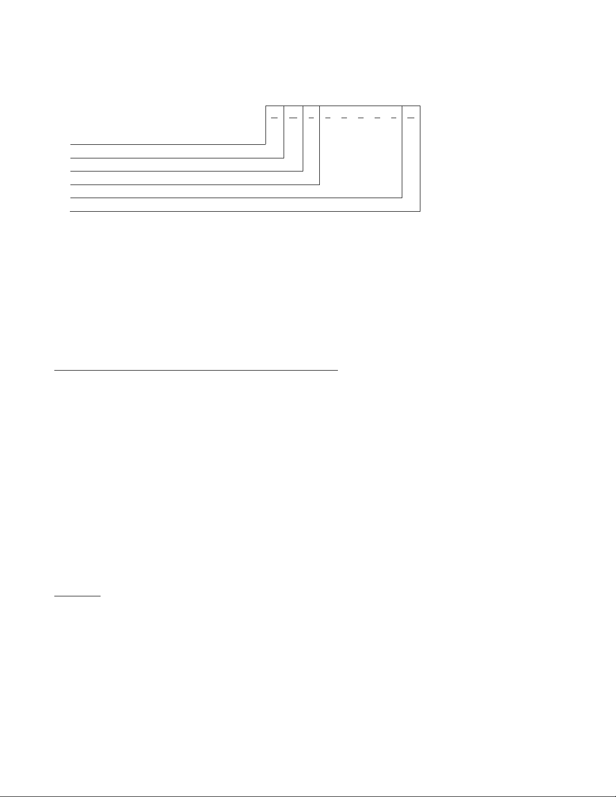
Model Number
*Note: The exterior colour, ll = Integrated, requires a panel kit
G L D 9 3 1 2 P 0 0 W W
Brand
G=GE
Size
L=Long Door
Product Type
D=Built-in
Platform
9 = Fully Integrated
Feather Pack
Number of Buttons
Model Year Designator
Engineering Model Suffix
Exterior Colour
WW = White on White
SS = Stainless Steel
BB = Black
4
Page 5
Serial Number
The model number and serial number are located inside the door jam.
The first two characters of the serial number identify
1 2 3 4 5 6 7 8 9
H
1 Date Code -Month -( Alpha)
2 Calendar Year Code (Alpha)
3 Model Class Code
4,5,6,7,8 Serial Number
9 Manufacturing Location
M 7 0 0 0 0 1 H
Column 1 Denotes the fiscal month of manufacture
Column 2 Denotes the fiscal year of manufacture (See Date of Manufacture Code Table below)
Column 3 Denotes the product being produced (regardless of Brand)
Columns 4 to 8 Model Class Code for Built-In dishwasher Products = 7 denotes the order of manufacture within a given
time period. The sequence will start with 00001 and progress until 99999 is reached or the fiscal
month has changed. The 5 digits need not be reset to the start of the numbering sequence each
month. This is left to the discretion of the factory.
Column 9 A letter, which will designate where the appliance was manufactured according to the following code:
H = Haier.
DATE OF MANUFACTURE CODE TABLE (For column 1 & 2)
A – Jan. A 2001, 2013
B – Feb. D 2002, 2014
F – Mar. F 2003, 2015
G – Apr. G 2004, XXXX
H – May. H – 1993 2005
L – June. L – 1994 2006
M – July. M – 1995 2007
R – Aug. R – 1996 2008
S – Sept. S – 1997 2009
T – Oct. T – 1998 2010
V – Nov. V – 1999 2011
Z – Dec. Z – 2000 2012
Example:
Using the example from the previous page. - HM700001H:
H = May
M = 2007
7 - Built-In Dishwasher
00001 = sequential production number
H = Haier
5
Page 6
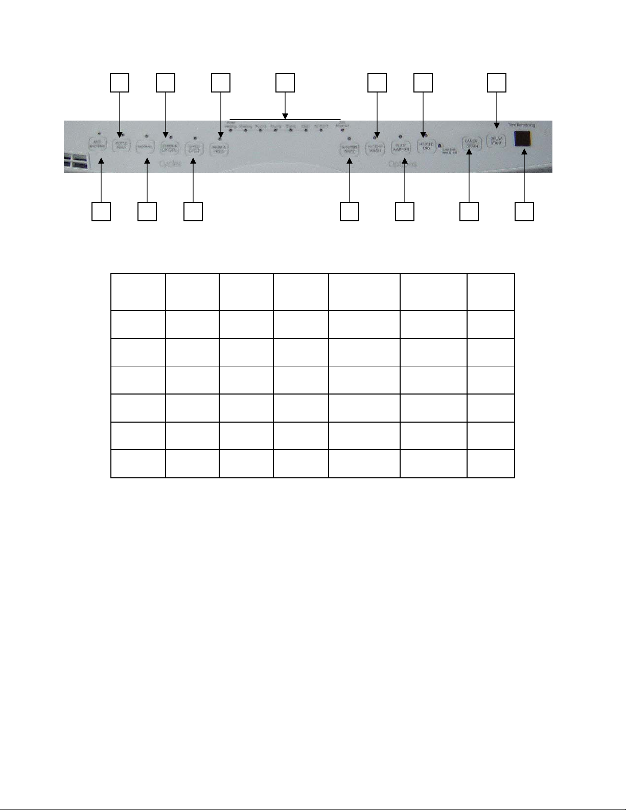
Control Features
2 4 1 13 7 9 11
1 3 5 6 8 10 12
Cycles
Cycle
Anti-
Bacterial
Pots &
Pans
Normal
Wash
China
Crystal
Speed
Wash
Rinse
Hold
NOTE: The sensor in the dishwasher monitors the soil level. Cycle time and/or water usage can vary
from the numbers above as the sensor adjusts the cycle for the best wash performance.
1. Anti-Bacterial - Use this cycle for all day-today soil types, including both normal and heavy
soils, giving you exceptional cleaning performance combined with reassuring sanitization.
2. Pots & Pans - Use this cycle for hard-to-clean, baked-on cookware and harder than normal
water conditions.
3. Normal - Use this cycle for loads with normal amounts of food soil. During the Main Wash,
the wash action will repeatedly pause for several seconds.
4. China & crystal - Use this cycle for china and crystal. This cycle uses a light wash and gentle
dry. During the heated dry, the heating element cycles on and off.
Max # of
Pre-wash
Cycles
Max # of
Wash
Cycle
2 1 4 42 110 150 160 10
2 1 4 38 104 140 150 10
2 1 4 23 99 120 130 10
1 1 1 30 52 130 135 10
0 1 1 19 120 130 10
0 0 1 12 12 / / /
Rinse
Cycles
Wash
Time
Min Max
Wash
Temperature
Min Max
Heated
Dry
Time
6
Page 7

5. Rinse & Hold - Use this rinse cycle for rinsing dishes, glasses and silverware that will not be
washed right away.
Options
6. Sanitize Rinse - Select this option to raise the water temperature in the final rinse to
approximately 160°F (71°C). The SANITIZE RINSE option adds heat and time to the cycle. This
high temperature rinse sanitizes your dishes and glassware in accordance with NSF/ANSI
standard 184 for residential dishwasher. Certified residential dishwashers are not intended
for licensed food establishments. ANTI-BACTERIAL WASH automatically uses this option.
SANITIZE RINSE is an option with the POTS & PANS and NORMAL cycles.
7. HI-TEMP WASH is an option with the POTS & PANS and NORMAL cycles. Always use HI-TEMP
WASH if you have hard water.
8. Plate Warmer- Use the PLATE WARMER option to warm serving dishes or dinner plates.
9. Heated Dry- Select this option to dry dishes with heat. HEATED DRY is an option with the
ANTI-BACTERIAL WASH, POTS & PANS, NORMAL and CHINA cycles.
Child Lock - Press & hold CHILD LOCK you can lock the controls to prevent any selections
from being made. Or you can lock the controls after you have started a cycle.
Children cannot accidentally start a dishwasher by touching pads with this option selected.
To unlock the dishwasher controls, press and hold the HEATED DRY pad for 3 seconds. To
lock the dishwasher, press and hold the HEATED DRY pay for 3 seconds. An indicator light
shows when CHILD LOCK is activated.
10. Drain Cancel ( GLD8110 GLD8312) Start Reset (GLD9312) - To change a cycle after washing
starts.
GLD8110-PLD8312 Series: Touch the DRAIN/CANCEL pad to cancel the cycle. Then the
water is pumped out if needed. This takes approximately 2 minutes.
GLD9312 Series: Open the door slowly to prevent splash-out. Touch the START/RESET pad to
cancel the cycle. If the START/RESET light is on, close the door until the water pumps out (this
takes approximately 2 minutes) and the light stops flashing.
When the light stops flashing, the dishwasher can be reprogrammed and restarted.
11. Delay Hours - You can delay the start of a wash cycle for up to 12 hours (GLD8110 GLD8312)
or 24 hours (GLD9312). Press the DELAY START pad to choose the number of hours you want
to delay the start of the cycle; then press START/RESET.
NOTE: To cancel the DELAY START selection before the cycle begins, press the DELAY START
pad until the display is blank
12. Time Remaining – A two digit display that shows the wash time left. This may reduce or
increase based on the readings of the Clean Sensor. It will display in minutes up to 99.
Between 100 and 120 Minutes it will show 2h (2 hours) and between 120 and 180 minutes it
will show 3h (3 hours)
7
Page 8

13. Status Indicators
Note: Status Indicators vary by model
The Status display tells you what is happening while the dishwasher is in operation and may flash,
indicating a malfunction. The lights will come ON indicating the sequence of the dishwasher
operation.
WASHING On during pre-wash and main wash periods
RINSING On during rinse periods
DRYING On during dry periods.
SANITIZED On when cycle has met Sanitization requirements
CLEAN On when a wash cycle is complete and Options are complete.
ADD RINSE AID On when the rinse aid is empty
WATER HEATING On when the dishwasher is heating the water
8
Page 9

Component Locator
1. Upper Spray . 7. Split Folding Utility Shelf (4)
2. Top Rack Track 8. Adjustable Top Rack
3. Water Inlet Opening. (in tub wall). 9. Middle Spray Arm
4. Lower Spray Arm 10. Removable Silverware Basket
5. Bottom Rack 11. Overfill Protection Float
6. Vent System 12. Heating Element
13. Detergent and Rinse Aid Dispenser
9
Page 10

Vent
Assembly
Vent Wax
Motor
Dispenser
Assembly
Inside Door Panel after front panel has been removed
Latch
Assembly
Interlock
Switch
Control
Board
Fill Solenoid
Electrical
Junction Box
Schematic is located behind the bottom kick plate
10
Page 11

Bottom View
Fill
Valve
Thermal
Safety
Wash
Motor
Wash
Sump
Float
Switch
Clean
Sensor
Drain
Motor
Temperature
Sensor
Heating
Element
11
Page 12

Component Removal
Removing Upper Rack
1. Pull tab out and remove the end cap
2. Pull the rack straight out and off the rails.
3. Replace the end caps.
4. Push the rails all the way back into the
dishwasher and pull upper rack all the way
out
Tab
Middle Spray Arm
Check holes in spray arm on for bits of foreign
matter.
Check spray arms for rotation
REMOVAL AND REPLACEMENT
1. Pull upper rack all the way out
2. Unscrew the plastic collar holding the spray
arm to the upper rack
.
Lower Spray Arm, Fine Filter, and Inlet Cover
Check the holes in the arm for bits of foreign
matter. Also check the spray wash arm for
rotation. Clean the fine filter screen if soil is
present.
The lower spray wash arm can be removed by
gently lifting and rotating it counter clockwise.
Wash Pump Disassembly
1. Remove the lower spray arm
2. Remove the 3 screws holding the hub.
3. Detach the water conduit from the tub
assembly.
4. Lift the water conduit and hub straight up to
remove from the pump.
Holding Clips
Water
Conduit
3 screws
.
Collar
12
Page 13

Wash Pump Disassembly con’t
5. Remove 2 screws holding the fine filter
assembly and lift to remove.
Press on
Nut
2 screws
6. Remove the 1 screw holding the coarse filter.
Lift out the coarse filter.
7. Remove the 2 screws holding the inlet
protector.
Screw
3. Remove the pulveriser blade, screen, spring and
washers.
Order of pulveriser components
4. Tip dishwasher on its back. Remove the one
Philips head screw that holds the motor in
place. It is located behind the cardboard shield.
Philips head
screw
Wash Motor
1. Disassemble the wash pump (see procedure)
2. Remove the press on nut to disassemble the
pulveriser
5. Disconnect the motor connector and rotate the
2 Screws
13
motor clockwise until it disengages from the
sump.
Note: Before removing the wash motor, remove the
water from the sump with a syringe
Drain Pump
1. Disconnect the pump connector
2. Press the tab and rotate the pump assembly
counter clockwise to remove.
Page 14

Tab
Fill Funnel
The top section of the fill funnel separates from the
main body. The fill funnel body is held in place by a
nut (located on the inside of the dishwasher).
Rotate the nut counter clockwise to remove the
main body. There is an O-ring seal between the fill
funnel and dishwasher tub. Make certain the O-ring
is fully seated when reinstalling.
Heating Element
The heating element nuts are located on the
underside of the washer, near the door. Ample
force is required to remove the nuts.
Removing the dishwasher from installation
may be required.
14
Page 15

Door Panel
The door panel covers the main control board,
detergent cup, vent, wax motor, louver, and
door-interlock switch. The outer door panel is
held in place by 14 screws (7 Phillips head
screws per side)
NOTE: Ribbon cable(s) connect the keypad
membrane (2-digit display on some models)
to the control circuit board. Due to the ribbon
length, care much be taken when removing
the door panel to ensure that the ribbon
cable(s) are not damaged.
Membrane Keypad
The door panel must be removed to access
the membrane keypad (see Door Panel).
When removing the membrane keypad, peel
the keypad from right to left.
On models with an LED display, the display is
held in place with a plastic clip.
NOTE: When replacing the keypad membrane,
always run the Service Mode to calibrate the
keypad membrane to the control board.
Control Module
The door panel must be removed to access
the control module (see Door Panel). The main
control is considered a “smart” control,
capable of learning the water temperature
and turbidity characteristics of the home.
It is normal if the cycle times vary over a
period of time from the factory default
settings due to temperature and water
quality.
The control module is held in place by two
screws that secures the module to the right
side of the inner door panel.
15
Page 16

Troubleshooting
Service Mode
To enter service mode, ensure door is closed
and press the following keys.
High Temp Wash. – Heat Dry - High Temp
Wash
If followed correctly Dishwasher will enter into
SERVICE MODE
All LED will illuminate indicating that they are
functioning properly
Has no diagnostics
Press Pots& Pans to activate
Water Solenoid Valve
Press Normal to activate Wash
Motor
Press China & Crystal to
activate Detergent Dispenser
Press Speed Cycle to activate
Heater and Wash Motor
Press Sanitize Darin Pump will
run for two min.
Circulation Pump and Motor
The Dishwasher must be removed from its
installation to gain access to the circulation
pump and motor. The circulation pump can
be activated using Test Mode. Refer to
schematic or strip circuit for motor resistance
value.
It is important to remember the motor does
not start immediately when the dishwasher
cycle has started. If the motor hums, but will
not start, make certain the pump impeller is
free from obstruction and the motor shaft can
turn freely.
The terminals on the induction motor are
labelled L1 and N. The motor is thermally
protected (internally) through the L1 side. The
wiring connector is blue to match the wire
leading to the motor. It is designed to go only
one way on the terminals. Make certain the
connector is fully seated when installing.
Heating Element
The heating element can be activated using
Service Mode.
The dual-wattage heating element produces
850 watts during wash, to help heat the
water, and an effective wattage due to
cycling of 541 watts during the dry cycle.
Water inlet temperature must be at least
120’F for proper drying. If the problem is that
the dishes are not drying correctly, don’t
overlook the rinse agent. A rinse agent will
improve the water sheeting action and drying
performance. It is normal for the stainless
steel tub and inner door panel to retain water
droplets even though the dishes are dry.
16
Page 17

Clean Sensor
The clean sensor measures the amount of
suspended particles in the wash water in the
sump. The control sends the turbidity sensor a
pulse with modulated 5 volt signal for
calibration and usage during operation
Red
White
Blue
Temperature Sensor:
The dishwasher uses a thermocouple to
measure water temperature. The sensor has a
negative temperature coefficient - as the
temperature rises, the sensor resistance
decreases. At room temperature (25 Degrees
Celsius), the temperature sensor will have a
resistance of 11 K and at 60 degrees Celsius,
the temperature sensor resistance will be 2.8
K
Drain Motor
Drainage system consists of the following
components:
Drain motor
Drain hose (one way check valve)
Water Valve and Flood Switch
The water valve is a 120 VAC solenoid valve
that is switched on/off by the control module.
The flood switch acts as a safety switch ONLY
and does not control normal operation of the
water valve. The flood switch opens the L1
side of the water valve circuit.
The switch is normally open. The weight of the
flood switch float holds the switch closed. The
flood switch will not stop the flow of water if
the valve sticks open from a mechanical
failure.
The water valve can be replaced with the
dishwasher installed.
WARNING: Disconnect power to dishwasher
before servicing water valve and flood switch.
The flood switch is held in place by 2 Phillips
head screws.
Water Valve Test
Attempt to activate water valve using Service
Mode. Pump out water as necessary using
Service Mode. If an intermittent failure is
suspected, activate water valve 5 times using
Service Mode. Water valve should stay on for
50 to 71 seconds per activation and should
not turn on and off during the 50 to 71 second
activation time.
If the water valve is not operating properly or
water level is low, check the following:
17
Page 18

Water valve, flood switch, flood switch float
and stem, transorb, and then main control.
The flood switch should open when the water
level is approximately ¼ in. above the base
(bottom) of the float dome.
Resistance through the water valve solenoid –
900 to 1200
Clogged screen in water valve.
Control Module
The door panel must be removed to access
the control module (see Door Panel). The main
control is considered a “smart” control,
capable of learning the water temperature
and turbidity characteristics of the home.
It is normal if the cycle times vary over a
period of time from the factory default
settings due to temperature and water
quality.
The control module is held in place by two
screws that secures the module to the right
side of the inner door panel.
P2-1 Rinse Aid Sensor (on some models),
P2-2 – Thermostat,
P2-3- Inlet Valve,
P2-4- Dispenser,
P2-6 – Door Interlock Switch (Double Black
Wires),
P3 – Drain Motor,
P5 & P9 – Washing Motor,
P6 – Heater Element,
P7 – Door Interlock Switch (Double White
Wires),
P8 – door Interlock Switch (single Black Wire),
P10 Wax Motor connector,
CN1 + CN6 – Door Panel,
CN2 – Display Board.
Detergent/ Rinse Module
At the second activation (3), the lever lifts the
connecting rod by the notch. This action lifts
the door. The door panel must be removed to
access the rinse dispenser plunger and
release the rinse detergent/rinse module (see
Door Panel) agent. When deactivated, the
lever returns to its original starting position.
The detergent rinse module is held in place by
6 Phillips head screws and 2 brackets.
Detergent/ Rinse Module
The detergent/rinse module automatically
dispenses both the detergent and the rinse
agent at the appropriate times. The module is
activated 2 times during a wash cycle.
Detergent is dispensed at the beginning of the
main wash cycle and rinse agent at the
beginning of the final rinse. The
detergent/rinse module can be activated
using Service Mode.
18
Page 19

Active Vent
If the door is unlatched while running a wash
cycle, the cycle countdown will pause and the
vent will open.
The active vent consists of the wax motor and
housing. The active vent helps to reduce the
noise level and heat loss when in the closed
position. The control module supplies 120
VAC to the wax motor. The control module
reverses polarity to drive the motor in a
clockwise or counter clockwise (open or
closed) direction.
The vent closes about 2 minutes after the
main pump is switched on during the first fill
cycle and opens during the drying cycle
(heated and non-heated). The vent is open
during cool-down periods or when the unit is
not in use.
If the vent is closed and the door is opened
during the wash cycle, the vent will open.
When the door is closed again, the vent will
remain open for 2 minutes, and then close
again to finish the cycle.
It is normal for water vapour to come through
the active vent during the dry cycle. The
active vent can be opened and closed using
the Service Mode.
19
Page 20

Schematic
Vent Wax motor
20
Page 21

CONSUMER WARRANTY
Your appliance is warranted to be free of defects in material and workmanship.
English
How Long
What is covered
All parts
Warranted
(From Date of Sale)
One (1) year
Terms and Conditions:
This warranty applies only for single family
domestic use in Canada when the appliance has
been properly installed according to the
instructions supplied by Mabe and is connected
to an adequate and proper utility service.
Damage due to abuse, accident, commercial
use, and alteration or defacing of the serial plate
cancels all obligations of this warranty.
Service during this warranty must be performed
by an Authorized Mabe Service Agent.
Neither Mabe nor the Dealer is liable for any
claims or damages resulting from any failure of
the dishwasher or from service delays beyond
their reasonable control.
To obtain warranty service, purchaser must
present the original bill of sale. Components
repaired or replaced are warranted through the
remainder of the original warranty period only.
This warranty is extended to the original
purchaser and any succeeding owner for
products purchased for home use within
Canada. In home warranty service will be
provided in areas where it is available and
deemed reasonable by Mabe to provide.
Parts
Repair or Replace
at Supplier’s Option
One (1) year
Labour
One (1) year
What Is Not Covered
• Service trips to your home to teach you how to
use the product.
• Damage to finish after delivery.
• Improper installation – proper installation
includes adequate electrical, plumbing and
other connecting facilities.
• Replacement of house fuses or resetting of
circuit breakers.
•
Replacement of light bulbs.
•
Damage to product caused by accident, fire,
floods or acts of God.
•
Proper use and care of product as listed in the
owner’s manual, proper setting of controls.
•
WARRANTOR IS NOT RESPONSIBLE FOR
CONSEQUENTIAL DAMAGES.
EXCLUSION OF IMPLIED WARRANTIES – Your sole and exclusive remedy is product repair as
provided in this Limited Warranty. Any implied warranties, including the implied warranties of
merchantability or fitness for a particular purpose, are limited to one year or the shortest
period allowed by law.
IMPORTANT
Keep this warranty and your bill of sale as proof of original purchase and purchase date.
Mabe Service is available coast to coast.
To schedule service, call 1.800.561.3344
If further help is needed concerning this warranty, contact:
Manager, Consumer Relations, Mabe Canada, Inc.,
Suite 310, 1 Factory Lane, Moncton, N.B. E1C 9M3
Staple your receipt here.
Proof of the original purchase date is
needed to obtain service under the
warranty.
30
 Loading...