

Page 1

GE
Installation Guide
Lighting
GE LED Wall Washer
LED Lighting System
Product Codes
62191, 62192, 62195, 62196, 62199, 62200, 62202, 62203, 62204, 62205, 62206,
62207, 65444, 65445, 65446, 65447, 65448, 65449
BEFORE YOU BEGIN
Read these instructions completely and carefully.
WARNING/AVERTISSEMENT
RISK OF ELECTRIC SHOCK
• Turn power off before inspection, installation or removal.
• Properly ground the LED system.
RISK OF FIRE
• Follow all NEC and local codes.
Save These Instructions
This product is intended solely for the use of nonresidential architecture lighting and is not intended for
use in any other application.
RISQUES DE DÉCHARGES ÉLECTRIQUES
• Coupez l’alimentation avant l’inspection, l’installation ou le déplacement.
• Mettre à terre le système DEL de la façon appropriée.
RISQUES D’INCENDIE
• Respectez tous les codes NEC et codes locaux.
Prepare Electrical Wiring
Electrical Requirements
• Do not use in wet locations.
• The grounding and bonding of the LED system shall
be done in accordance with National Electric Code
(NEC) Article 600.
• Follow all National Electric Codes (NEC) and local codes.
imagination at work
Page 2

Components
GE LED Wall Washer Fixtures
1
1
3
4 5
2
6
Leader Cable with End Cap (62208, 62211)
2
Mounting track with bracket (65467)
3
UL approved 18-14 AWG (0.82-2.08 mm2) wire
4
connectors or In-Line Splice Connector (75545)
#10 (M5) self-tapping athead screws
5
(Optional) jumper cable (62209: 12 in. /305 mm long,
6
62210: 48 in./1219 mm long)
Standard Mounting Methods
Fixture mounting positions:
It is recommended that the LED xtures be installed into a space no smaller than 3 in. x 3 in. (76mm x 76mm) For
additional mounting practices refer to application notes on our website (www.gelightingsolutions.com)
Ceiling
Wall
CeilingCeiling Ceiling
Wall
Fixture rotation:
Light can be directed from 0 to 50 degrees in 10 degree increments in both directions with the help of 1) the rotation
angle of the xture, and 2) the mounting edge of the xture track.
40°
50°
Wall
30°
Mounting surface
20°
Wall
Mounting track can be installed
at 0 and 30 degree angles
Fixture has three positions
at 10 degree increments
10°10°
20°
30°
40°
50°
0°
Material Estimations
For material estimations, take the length of the run in feet divided by 1.05 feet to get the quantity of xtures needed.
Take the run in feet divided by 4 feet to get the quantity of mounting tracks needed.
Page 3
Leader cable to LED xture
Gray (-0-10V)
Blue (+0-10V)
Black (+)
White (-)
Green (ground)
120-277V
AC Line
Dimmer
Leader cable to LED xture
Gray (-0-10V)
Black (+0-10V)
Brown (+)
Blue (-)
Green/yellow
(ground)
240 VAC
Line
Dimmer
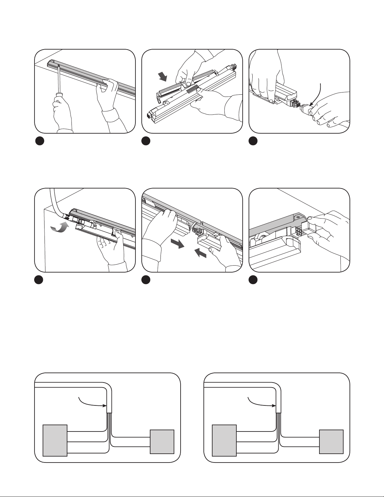
Installation
Leader cable
Install mounting track inside the
1 2
wall cavity using a minimum
of two #10 (M5) self-tapping
athead screws per section. If
required, cut mounting track to
desired length.
Snap in LED xture
Snap the rst LED xture into the
4
mounting track.
Assemble the LED xture and
the bracket by pressing them
together.
Orient plugs male to female
Continue placing xtures, being
5 6
sure to join plugs male to female.
Attach jumper cables as needed
to work around any obstacles,
corners or separations.
Connect the leader cable to the
3
male plug on the rst LED xture.
Place end cap from leader cable
on the electrical plug of the last
xture in the run.
Electrical Connections
Connect the leader cable to the power source and dimmer.
OPTIONAL: If dimming is not used, cap the purple and gray wires with UL approved wire connectors. Do not connect the
wires together.
Page 4
Troubleshooting
Symptom Solution
All LED xtures are not
illuminated
• Check leader cable connection and/or check circuit breaker.
• Check plug connectors on the LED xtures for improper connections or short circuits.
• Ensure leader cable is securely connected to the female plug connector on the rst LED xture.
Some LED xtures are
not illuminated
• Check plug connectors on the LED xtures for improper connections or short circuits.
• Ensure any jumper cables are securely connected between the male/female plug connectors of the
LED xtures.
Shadows within
application
• Re-position LED xtures along mounting surface ensuring architectural elements are not directly in
front of any LEDs.
• Adjust layout of LED xtures to ensure uniformity of illumination.
• Adjust leader cable and/or jumper cable orientation to ensure cables do not cover any LEDs.
Specications
Product Code Description Code Voltage IP Rating
62199 (LWW1-HO12-012-827) 120 VAC-277 VAC, 50-60Hz IP51: Dry or Damp Location
62202 (LWW1-HO12-030-827) 120 VAC-277 VAC, 50-60Hz IP51: Dry or Damp Location
62191 (LWW1-HO12-110-827) 120 VAC-277 VAC, 50-60Hz IP51: Dry or Damp Location
65444 (LWW1-HO12-012-830) 120 VAC-277 VAC, 50-60Hz IP51: Dry or Damp Location
65445 (LWW1-HO12-030-830) 120 VAC-277 VAC, 50-60Hz IP51: Dry or Damp Location
62192 (LWW1-HO12-110-830) 120 VAC-277 VAC, 50-60Hz IP51: Dry or Damp Location
62200 (LWW1-HO12-012-840) 120 VAC-277 VAC, 50-60Hz IP51: Dry or Damp Location
62203 (LWW1-HO12-030-840) 120 VAC-277 VAC, 50-60Hz IP51: Dry or Damp Location
62195 (LWW1-HO12-110-840) 120 VAC-277 VAC, 50-60Hz IP51: Dry or Damp Location
62204 (LWW1-MO12-012-827) 120 VAC-277 VAC, 50-60Hz IP51: Dry or Damp Location
62206 (LWW1-MO12-030-827) 120 VAC-277 VAC, 50-60Hz IP51: Dry or Damp Location
62196 (LWW1-MO12-110-827) 120 VAC-277 VAC, 50-60Hz IP51: Dry or Damp Location
65446 (LWW1-MO12-012-830) 120 VAC-277 VAC, 50-60Hz IP51: Dry or Damp Location
65447 (LWW1-MO12-030-830) 120 VAC-277 VAC, 50-60Hz IP51: Dry or Damp Location
65448 (LWW1-MO12-110-830) 120 VAC-277 VAC, 50-60Hz IP51: Dry or Damp Location
62205 (LWW1-MO12-012-840) 120 VAC-277 VAC, 50-60Hz IP51: Dry or Damp Location
62207 (LWW1-MO12-030-840) 120 VAC-277 VAC, 50-60Hz IP51: Dry or Damp Location
65449 (LWW1-MO12-110-840) 120 VAC-277 VAC, 50-60Hz IP51: Dry or Damp Location
Maximum Run Length
For 120 VAC: 70 Fixtures
(~73.5 feet/22.41m)
For 240 VAC: 140 Fixtures
(~147 feet/44.82m)
For 277 VAC: 165 Fixtures
(~173.3 feet/52.84m)
For 120 VAC: 140 Fixtures
(~147 feet/44.82m)
For 240 VAC: 290 Fixtures
(~304.5 feet/92.84m)
For 277 VAC: 300 Fixtures
(~315 feet/96.04m)
This device complies with Part 15 of the FCC Rules. Operation is subject to the following two conditions: (1) This device may not cause harmful interference, and (2) this device must accept any interference received, including interference that may cause undesired operation. This
Class [A] RFLD complies with the Canadian standard ICES-003. Ce DEFR de la classe [ A ] est conforme á la NMB-003 du Canada.
Note: This equipment has been tested and found to comply with the limits for a Class A digital device, pursuant to part 15 of the FCC Rules.
These limits are designed to provide reasonable protection against harmful interference when the equipment is operated in a commercial
environment. This equipment generates, uses, and can radiate radio frequency energy and, if not installed and used in accordance with the
instruction manual, may cause harmful interference to radio communications. Operation of this equipment in a residential area is likely to
cause harmful interference in which case the user will be required to correct the interference at his own expense.
GE Lighting • 1-888-MY-GE-LED
GE Lighting Solutions, LLC is a subsidiary of the General Electric Company. Tetra is a trademark of GE Lighting. The GE brand and logo are trademarks of the General Electric Company.
© 2013 GE Lighting Solutions, LLC. Information provided is subject to change without notice. All values are design or typical values when measured under laboratory conditions.
(1-888-69-43-533)
• www.gelighting.com
ARCH053-100213
 Loading...