


Range Hoods
Hottes de cuisinière
www.GEAppliances.ca www.electromenagersge.ca
Owner’s Manual and
Installation Instructions
PVUS930 PVUS936
Safety Instructions ....................1, 2
Operating Instructions ................. 3, 4
Carbon Filter .............................3, 4
Grease Filter .............................3, 4
Care and Cleaning. . . . . . . . . . . . . . . . . . . . .5, 6
Charcoal Filter .............................5
Grease Filter ...............................5
Hood Lights ................................6
Stainless Steel Surfaces. . . . . . . . . . . . . . . . . . . . .6
Installation Instructions ............. 7–16
Troubleshooting Tips ...................17
Consumer Support
Consumer Support ........................21
Product Registration .......................18
Warranty .................................20
Write the model and serial numbers here:
Model # _______________________________
Serial # _______________________________
Manuel de l’utilisateur et
instructions d’installation
PVUS930 PVUS936
Sécurité ...........................22, 23
Utilisation .........................24, 25
Filtre à charbon .......................24, 25
Filtre à graisses .......................24, 25
Entretien et nettoyage ..............26, 27
Filtre à charbon ..........................26
Filtre à graisses ..........................26
Lampes de la hotte .......................27
Surfaces en acier inoxydable .............27
Installation .......................28 à 37
Dépannage ........................... 38
Service à la clientèle
Enregistrement du produit ................18
Garantie .................................40
Service à la clientèle ......................41
Inscrivez ici les numéros de modèle et de série :
Nº de modèle _____________________________
Nº de série _______________________________
<ou can ¿nd them on a label on the bacN Zall
of the hood, behind the removable mesh ¿lters.
Ces numéros se trouvent sur une étiquette située
j l·arriqre de la hotte, derriqre les ¿ltres j treillis
amovibles.
350A4502P737 04-13 ATS
IMPORTANT SAFETY INSTRUCTIONS.
FOR RESIDENTIAL USE ONLY.
READ AND SAVE THESE INSTRUCTIONS.
PLEASE READ ENTIRE INSTRUCTIONS BEFORE PROCEEDING.
IMPORTANT: Save these Instructions for the Local Electrical Inspectors use.
INSTALLER: Please leave these Instructions Zith this unit for the oZner.
OWNER: Please retain these instructions for future reference.
Safety InstructionsCare and Cleaning
7aNe care Zhen using cleaning agents or detergents.
Suitable for use in household cooNing area.
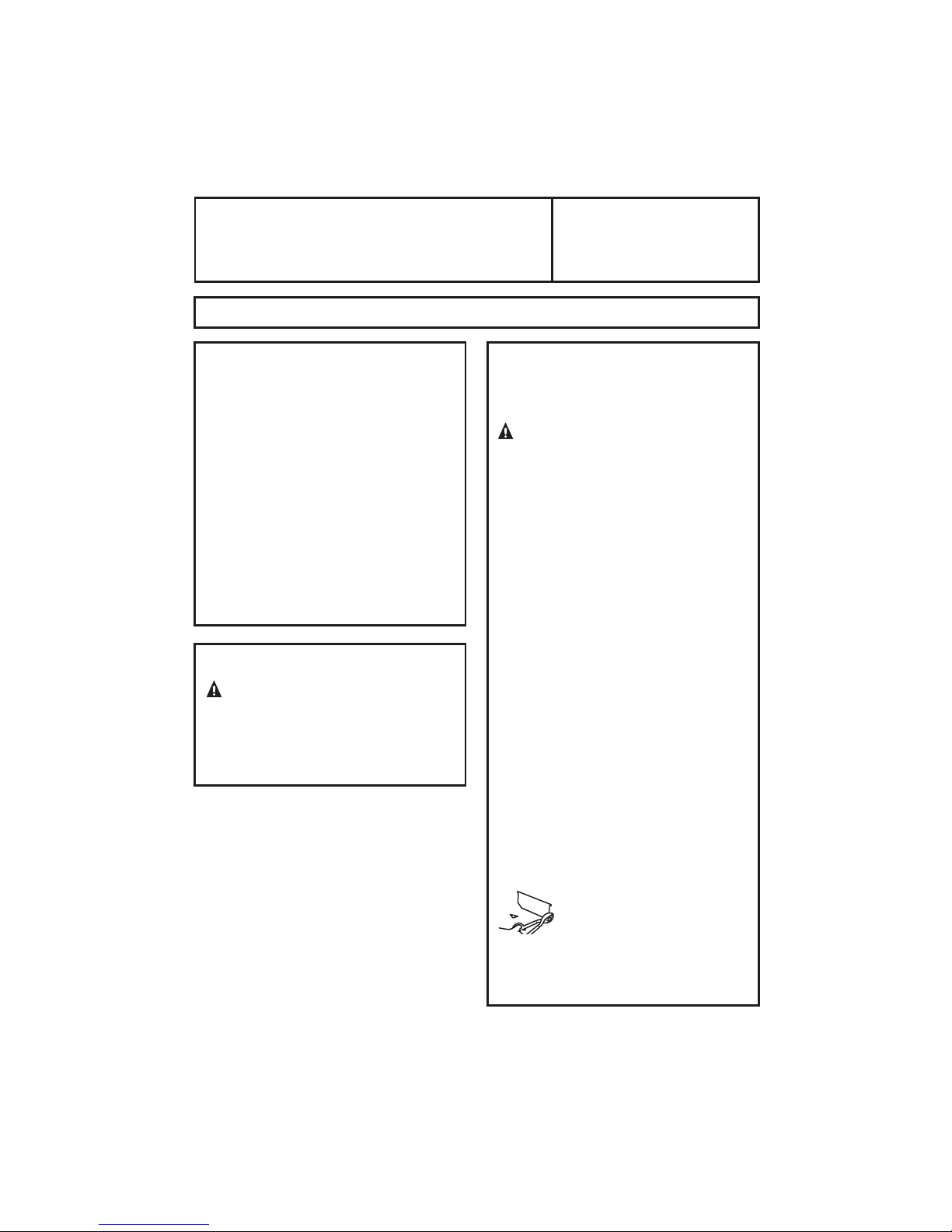
WARNIN G 7o reduce the risN of ¿re or electric shocN, do not use this fan Zith
any Solid-State Speed Control Device.
CAUTION - 7o reduce risN of ¿re and to properly exhaust air, be sure to duct
Operating
Consumer Support Troubleshooting Tips
air outside ² Do not vent exhaust air into spaces Zithin Zalls or ceilings or into
attics, craZl spaces, or garages.
Instructions
CAUTION - For general ventilating use only. Do not use to exhaust hazardous or
explosive materials and vapors.
CAUTION - To avoid motor bearing damage and noisy and/or unbalanced
impellers, Neep dryZall spray, construction dust, etc. off poZer unit.
CAUTION - Please read speci¿cation label on product for further information and
requirements.
WARNIN G – TO REDUCE THE RISK OF FIRE, ELECTRIC SHOCK, OR INJURY TO
PERSONS, OBSERVE THE FOLLOWING:
A. Use this unit only in the manner intended by the manufacturer. If you have
questions, contact the manufacturer.
B. Before servicing or cleaning unit, sZitch poZer off at service panel and locN
the service disconnecting means to prevent poZer from being sZitched on
accidentally. When the service disconnecting means cannot be locNed, securely
fasten a prominent Zarning device, such as a tag, to the service panel.
WARNING - TO REDUCE THE RISK OF A RANGE TOP GREASE FIRE:
A. Never leave surface units unattended at high settings. Boilovers cause smoNing
and greasy spillovers that may ignite. Heat oils sloZly on loZ or medium
settings.
B. $lZays turn hood ON Zhen cooNing at high heat or Zhen Àambeing foods i.e.
Crepes Suzette, Cherries Jubilee, Peppercorn Beef Flambè).
C. Clean ventilating fans frequently. Grease should not be alloZed to accumulate
on fan or ¿lter.
D. Use proper pan size. $lZays use cooNZare appropriate for the size of the surface
element.
E. Keep fan, ¿lters and grease laden surface clean.
F. Use high range setting on range only Zhen necessary.Heat oil sloZly on loZ to
medium setting.
G. Don·t leave range unattended Zhen cooNing.
H. $lZays use cooNZare and utensils appropriate for the type and amount off food
being prepared.
1
WARNING – TO REDUCE THE RISK OF INJURY TO PERSONS IN THE EVENT OF A
RANGE TOP GREASE FIRE, OBSERVE THE FOLLOWINGa:
A. S0OTHER FLA0ES Zith a close-¿tting lid, cooNie sheet, or metal tray, then turn
off the burner. BE CAREFUL TO PREVENT BURNS. If the Àames do not go out
immediately, EVACUATE AND CALL THE FIRE DEPARTMENT.
B. NEVER PICK UP A FLAMING PAN – You may be burned.
C. DO NOT USE WATER, including Zet dishcloths or toZels – a violent steam
explosion Zill result.
D. Use an extinguisher ONLY if:
1. You NnoZ you have a Class ABC extinguisher, and you already NnoZ hoZ to
operate it.
2. The ¿re is small and contained in the area Zhere it started.
3. The ¿re department is being called.
4. You can ¿ght the ¿re Zith your bacN to an exit.
a
Based on ´Nitchen ¿resafety tipsµ published by NFPA.
Proper maintenance of the Range Hood will assure proper performance of the unit.
WARNIN G - UNDER CERTAIN CIRCUMSTANCES DOMESTIC APPLIANCES MAY BE
DANGEROUS.
A. Do not checN ¿lters Zith hood ZorNing.
B. Do not touch the lamps after a prolonged use of the appliance.
C. No food must be cooNed Àambè underneath the hood.
D. The use of an unprotected Àame is dangerous for the ¿lters and could cause ¿res.
E. Watch constantly the fried food in order to avoid the cooNing oil Àares up.
F. Before performing any mainteinance operation, disconnect the hood from the
electrical service.
The manufacturers Zill not to accept any responsability for eventual damages,
because of failure to observe the above instructions.
Safety Instructions Care and Cleaning
Instructions
Operating
Troubleshooting Tips
Consumer Support
2
OPERATING INSTRUCTIONS
,IWKHDSSDUDWXVLVHTXLSSHGZLWKWKHIROORZLQJFRQWUROV)LJ
Push-button A = On/off lights sZitch.
Push-button B = On/off cooNer hood sZitch. The appliance sZitches on at speed
level 1, If the cooNer hood is on depress the push-button for 2 sec. to sZitch off the
cooNer hood. If the cooNer hood is at speed level 1 it Zill not be necessary to depress
the push-button to sZitch the cooNer hood off. Decreases the motor speed.
Display C = Indicates the motor speed level selected and activates the timer.
Safety InstructionsCare and Cleaning
Push-button D = SZitches on the cooNer hood. Increases the motor speed. Touching
the Ney at 3rd speed, the intensive function runs for 10 minutes, then the appliance
go bacN to ZorN at the original speed. During this function the display blinNs.
Key E = The Timer times the functions on activation for 15 minutes, after Zhich
they are sZitched off. The Timer is deactivated by re-pressing Key E. When the
Timer is activated the decimal point must Àash on the display. The Timer cannot be
activated if the intensive speed is functioning.
- The “clean airµ function is activated by pressing Ney E for 2 seconds Zhen the
Operating
Instructions
appliance is sZitched off. This sZitches the motor on for 10 minutes every hour at
the ¿rst speed.
During functioning a rotary movement of the peripheral segments must be
visualised on the display. When this time has passed the motor sZitches off and
the ¿xed letter “Cµ must be visualised on the display until the motor re-starts after
50 minutes for another 10 minutes and so on. Press any Ney apart from the light
Neys to return to normal functioning. Press Ney E to deactivate the function.
$FWLYHFDUERQJUHDVH¿OWHUVDWXUDWLRQ
- When display item C Àashes, at a speed Zhere it alternates Zith the letter F e.g. 1
and F), the grease ¿lters must be Zashed.
- When display item C Àashes, at a speed Zhere it alternates Zith the letter A e.g. 1
and A), the carbon ¿lters must be replaced.
After the clean ¿lter has been positioned correctly, the electronic memory must
be reset by pressing button A for approximately 5 seconds, until the indication F
or A shoZn on the display C stops Àashing.
Consumer Support Troubleshooting Tips
3
MAINTENANCE
We recommend that the range hood is sZitched on before any food is cooNed. We
also recommend that the appliance is left running for 15 minutes after the food is
cooNed, in order to thoroughly eliminate all contaminated air.
The effective performance of the range hood depends on constant maintenance;
the anti-grease ¿lter and the active carbon ¿lter both require special attention.
7KHDQWLJUHDVH¿OWHU is used to trap any grease particles suspended in the
air, therefore is subMect to saturation the time it taNes for the ¿lter to become
saturated depends on the Zay in Zhich the appliance is used).
- To prevent potential ¿re hazards, the anti-grease ¿lters should be Zashed a
minimum of every 2 months it is possible to use the dishZasher for this tasN).
- After a feZ Zashes, the colour of the ¿lters may change. This does not mean they
have to be replaced.
If the replacement and Zashing instructions are not folloZed, the anti-grease
¿lters may present a ¿re hazard.
7KHDFWLYHFDUERQ¿OWHUV (on some models) are used to purify the air Zhich is
released bacN into the room. The ¿lters are not Zashable or re-usable and must be
replaced at least once every four months. The active carbon ¿lter saturation level
depends on the frequency Zith Zhich the appliance is used, the type of cooNing
performed and the regularity Zith Zhich the anti-grease ¿lters are cleaned.
Clean the range hood frequently, both inside and outside, using a cloth Zhich has
been dampened Zith denatured alcohol or neutral, non-abrasive liquid detergents.
The light on the range hood is designed for use during cooN
room illumination. Extended use of the light reduces the average duration of the
bulb.
ing and not for general
Safety Instructions Care and Cleaning
Instructions
Operating
Troubleshooting Tips
Consumer Support
4
CARE AND CLEANING
Be sure electrical power is off and all surfaces are cool before cleaning or
servicing any part of the vent hood.
Reusable Metal Grease Filters
The hood has 3 metal reusable grease filters.
The metal filters trap grease released by foods on the cooNtop. They also help
Safety InstructionsCare and Cleaning
prevent flaming foods on the cooNtop from damaging the inside of the hood.
For this reason, the filters must ALWAYS be in place Zhen the hood is used. The
grease filters should be cleaned once a month, or as needed.
To remove, press the filter locNs bacN and pull the filters doZn and out.
To replace, insert the rear filter tabs in the frame slots at the bacN of the opening.
Push the filters up and locN them into place.
To clean the grease filters, soaN them and then sZish them around in hot Zater
Operating
and detergent. Don·t use ammonia or ammonia products because they Zill darNen
Instructions
the metal. Do not use abrasives or oven cleaners. Light brushing can be used to
remove embedded dirt. Rinse, shaNe and let them dry before replacing. They may
also be cleaned in an automatic dishwasher.
NOTE: Before cleaning, make sure the charcoal filters, if present, are unclipped and
removed. See the Charcoal Filters section.
Charcoal Filters (on some models)
The charcoal filters cannot be cleaned. They must be replaced.
For converting vent hood to recirculation mode not vented to the outside),
order The folloZing Nits:
KIT0320 for model PVUS930
KIT0321 for model PVUS936
These Nits contain charcoal filters.
For replacement charcoal filters, order Part no. ACK00059.
These Nits can be ordered from your GE supplier.
NOTE:&KDUFRDO¿OWHUVDUHnot included with the hood. They must be ordered from
your GE supplier.
If the model is not vented to the outside, the air Zill be recirculated through
disposable charcoal ¿lters that help remove smoNe and odors.
The charcoal ¿lters should be replaced Zhen they are noticeably dirty or discolored
usually after 6–12 months, depending on hood usage).
NOTE:'2127ULQVHRUSXWFKDUFRDO¿OWHUVLQDQDXWRPDWLFGLVKZDVKHU
Consumer Support Troubleshooting Tips
5
Stainless Steel Surfaces (on some models)
Do not use a steel-wool pad; it will scratch the surface.
1. ShaNe bottle Zell.
2. Place a small amount of CERAMA BRYTE
Conditioner on a dry cloth or dry paper toZel.
3. Clean a small area approximately 8µ x 8µ/20.3 cm x 20.3 cm), rubbing Zith the
grain of the stainless steel if applicable.
4. Dry and buff Zith a clean, dry paper toZel or soft cloth.
5. Repeat as necessary.
To order:
To order CERAMA BRYTE
our toll-free number:
National Parts Center 1.800.661.1616
www.GEAppliances.ca
CERAMA BRYTE
Stainless Steel Cleaning
Polish and Conditioner # PM10X313
®
®
Stainless Steel Cleaning Polish and Conditioner, please call
®
Stainless Steel Cleaning Polish and
Hood Lights
This hood requires tZo bulbs QRWLQFOXGHG, maximum 50 Zatts.
Purchase and install WB27M02956, 50 W Maximum halogen bulbs.
When replacing a bulb, let it cool ¿rst. MaNe sure that poZer to the light has been
turned off. Never alloZ a hot bulb to come into contact Zith Zater.
Safety Instructions Care and Cleaning
Instructions
Operating
WARNING: To reduce the risN of electric shocN, do not connect electrical poZer
to the hood Zithout both bulbs in place.
To change the light bulbs:
See page 4 and Fig.9.
CAUTION: Do not touch the hood light bulbs Zhen they are on. They may be
hot enough to cause injury.
The light bulbs operate at extremely high temperatures. If they
shatter, the hot glass could cause personal injury.
6
Troubleshooting Tips
Consumer Support
Installation Range Hood
Instructions
Questions? Call 800.561.3344
or visit our Website at:
BEFORE YOU BEGIN
Read these instructions completely and carefully.
:
IMPORTANT –
local inspector’s use.
:
IMPORTANT –
codes and ordinances.
:
Note to Installer –
instructions with the Consumer.
:
Note to Consumer –
for future reference.
: Skill level – Installation of this appliance requires
basic mechanical and electrical skills.
: Completion time – 30 minutes–3 hours
: Proper installation is the responsibility of the installer.
: Product failure due to improper installation is not
covered under the Warranty.
Save these instructions for
Observe all governing
Be sure to leave these
Keep these instructions
FOR YOUR SAFETY:
WARNING –
installation, switch power off at service panel and
lock the service disconnecting means to prevent power
from being switched on accidentally. When the service
disconnecting means cannot be locked, securely fasten
a prominent warning device, such as a tag, to the
service panel.
Before beginning the
GEAppliances.ca
DUCTWORK REQUIREMENTS
NOTE: Read the ductwork sections only if you do not
have existing ductwork. If you have existing ductwork,
skip to the “Damage” section and proceed.
WARNING –
TO PROPERLY EXHAUST AIR, BE SURE TO DUCT AIR OUTSIDE—
DO NOT VENT EXHAUST AIR INTO SPACES WITHIN WALLS OR
CEILINGS OR INTO ATTICS, CRAWL SPACES OR GARAGES.
The venting system must exhaust to the outside.
This hood can be vented vertically through upper cabinets
or horizontally through an outside wall. Ductwork is not
included.
Exhaust connection:
The hood exhaust has been designed to mate with
standard 6” diameter round ducting.
If a 7” round duct is required, a transition adaptor must be
used*. Do not use less than a 6” diameter duct.
Maximum duct length:
For satisfactory air movement, the total duct length
1
of a 3
⁄4” x 10” rectangular, 6” or 7” diameter round
duct should not exceed 65 equivalent feet. See the
WORKSHEET–CALCULATE TOTAL EQUIVALENT
DUCTWORK LENGTH section.
NOTE: It is important that ducting be installed using
the most direct route and with as few elbows as possible.
This ensures clear venting of exhaust and helps prevent
blockages. Also, make sure dampers swing freely and
nothing is blocking the ducts.
Elbows, transitions, wall and roofcaps, etc.,
present additional resistance to airflow and are equivalent
to a section of straight duct longer than their actual
physical size. When calculating the total duct length, add
the equivalent lengths of all transitions and adaptors plus
the length of all straight duct sections. The charts on the
following pages show you how to calculate total equivalent
ductwork length using the approximate feet of equivalent
length of some typical ducts.
TO REDUCE THE RISK OF FIRE AND
* IMPORTANT: If a rectangular-to-round
transition adaptor is used, the bottom
corners of the damper will have to be
cut to fit, using the tin snips, in order
to allow free movement of the damper.
Equivalent lengths of duct pieces
are based on actual tests and reflect
requirements for good venting
performance with any hood.
1 ft = 0.3 m; 1 in. = 2.5 cm
7
Installation Instructions
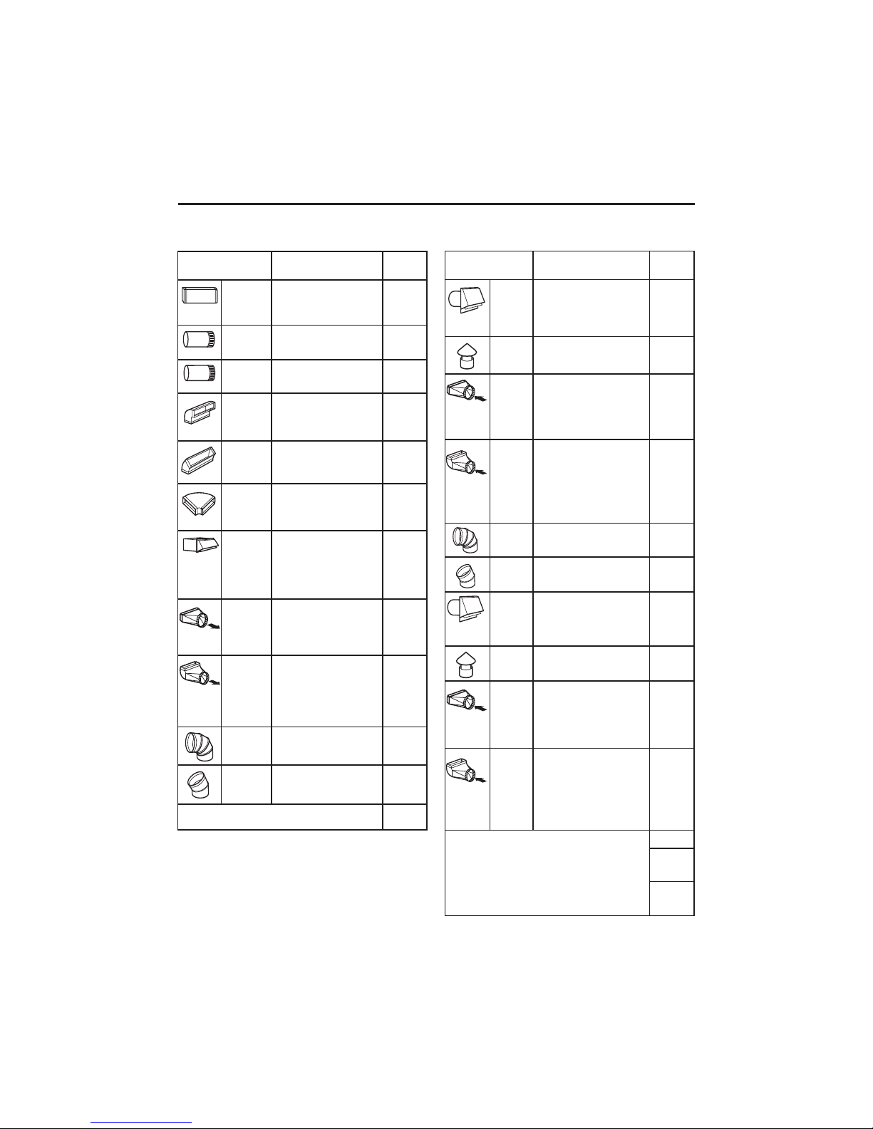
WORKSHEET—CALCULATE TOTAL EQUIVALENT DUCTWORK LENGTH
DUCT EQUIVALENT NUMBER
PIECES LENGTH x USED = TOTAL
31⁄4” x 10” 1 Ft. x ( ) = Ft.
Rect.,
straight
7” Round, 1 Ft. x ( ) = Ft.
straight
6” Round, 1 Ft. x ( ) = Ft.
straight
1
3
⁄4” x 10” 14 Ft. x ( ) = Ft.
Rect. 90°
elbow
1
⁄4” x 10” 8 Ft. x ( ) = Ft.
3
Rect. 45°
elbow
1
⁄4” x 10” 33 Ft. x ( ) = Ft.
3
Rect. 90°
flat elbow
1
3
⁄4” x 10” 24 Ft. x ( ) = Ft.
Rect.
wall cap
(18 ft. w/o
damper)
x ( ) = Ft.
with
damper
1
3
⁄4” x 10” 2 Ft. x ( ) = Ft.
Rect. to
6” round
transition
1
3
⁄4” x 10” 4 Ft. x ( ) = Ft.
Rect. to
6” round
transition
90° elbow
6” Round, 25 Ft. x ( ) = Ft.
90° elbow
6” Round, 16 Ft. x ( ) = Ft.
45° elbow
Subtotal column 1 = Ft.
MAXIMUM DUCT LENGTH: For satisfactory air movement,
the total duct length of a 3
1
⁄4” x 10” rectangular, 7” diameter
round duct should not exceed 65 equivalent feet.
DUCT EQUIVALENT NUMBER
PIECES LENGTH x USED = TOTAL
6” Round 53 Ft. x ( ) = Ft.
wall cap
with
(39 ft. w/o
damper)
damper
6” Round 72 Ft. x ( ) = Ft.
roof cap
6” Round 3 Ft. x ( ) = Ft.
to
1
3
⁄4” x 10”
rect.
transition
6” Round 9 Ft. x ( ) = Ft.
to
1
3
⁄4” x 10”
rect.
transition
90° elbow
7” Round, 14 Ft . x ( ) = Ft.
90° elbow
7” Round, 9 Ft . x ( ) = Ft.
45° elbow
7” Round 28 Ft. x ( ) = Ft.
wall cap (
with
21 ft. w/o
damper)
damper
7” Round 39 Ft. x ( ) = Ft.
roof cap
7” Round 1 Ft. x ( ) = Ft.
to
1
3
⁄4” x 10”
rect.
transition
7” Round 5 Ft . x ( ) = Ft.
to
1
3
⁄4” x 10”
rect.
transition,
90° elbow
x ( ) = Ft.
x ( ) = Ft.
Subtotal column 2 = Ft.
Subtotal column 1 = Ft.
Total ductwork = Ft.
1 ft = 0.3 m; 1 in. = 2.5 cm
8

Installation Instructions
DAMAGE – SHIPMENT/INSTALLATION
2If the unit is damaged in shipment, return the unit to the
store in which it was bought for repair or replacement.
Call 800.531.3344.
2If the unit is damaged by the customer, repair or
replacement is the responsibility of the customer.
2If the unit is damaged by the installer (if other than
the customer), repair or replacement must be made
by arrangement between customer and installer.
MOUNTING SPACE
24”, 30” or 36” to
match cooktop width
66” or
more from
the floor to
the top of
the hood
Bottom edge of
cabinet needs
to be 30” or
more from
the cooking
surface
30”
min.
TOOLS YOU WILL NEED
Flat-blade and Phillips
screwdrivers
Saw (saber or
keyhole)
1/4” pivoting
hex socket
Flashlight
Pliers
Caulking
Pencil
Electric drill
Tape measure
Level
PARTS YOU WILL NEED
6” round straight ducting
6” round 90° elbow ducting
6”-7” hose clamp (2)
Duct tape
Metal snips
(in some
applications)
Wire stripper
1/4” Nutdriver
NOTES:
2Hood width may be greater than the width of the range
or cooktop, but it may not be smaller.
2Ensure the range or cooktop is installed per
manufacturer’s installation instructions.
2If you are going to vent your range hood to the outside,
see the “Ducting Requirements” section for exhaust duct
preparation.
1 ft = 0.3 m; 1 in. = 2.5 cm
9

READ AND SAVE THESE INSTRUCTIONS.
GENERAL
Carefully read the folloZing important information regarding installation safety and
maintenance. Keep this information booNlet accessible for further consultations. The appliance
has been designed for use in the DUCTING version air exhaust to the outside Fig.1A - Fig.1B) or
FILTERING Optional KIT0320 for 30µ 7.2 cm) model and KIT0321 for 36µ 91.4 cm) model.
INSTALLATION INSTRUCTIONS
WARNING – TO REDUCE THE RISK OF FIRE, ELECTRIC SHOCK, OR INJURY TO PERSONS,
OBSERVE THE FOLLOWING:
A. Installation ZorN and electrical Ziring must be done by quali¿ed persons) in accordance
Zith all applicable codes and standards, including ¿re-rated construction.
B. Suf¿cient air is needed for proper combustion and exhausting of gases through the Àue
chimney) of fuel burning equipment to prevent bacN drafting. FolloZ the heating equipment
manufacturer’s guideline and safety standards such as those published by the National Fire
Protection Association NFPA), and the American Society for Heating, Refrigeration and Air
Conditioning Engineers ASHRAE), and the local code authorities.
C. When cutting or drilling into Zall or ceiling, do not damage electrical Ziring and other hidden
utilities.
D. Ducted fans must alZays be vented to the outdoors.
E. This unit must be grounded.
WARNIN G - TO REDUCE THE RISK OF FIRE, USE ONLY METAL DUCTWORK.
Attention!
- Before carrying out assembly operations, open the pacNaging, taNe the hood and place it
on a comfortable surface.
- Remove the anti-grease ¿lter/s Fig.1C).
A. If hood installation is used Zith the air outlet Fig.1B or Fig.4B, the Zires set-up in the
relevant Ziring harness must be released by pulling the lever outZards, as indicated in
¿gure 2, phase 1-2.
B. Disconnect the 6-Zay quicN coupling of the motor located inside of the hood, as shoZ in
¿gure 2. - phase 3.
C. The Zires positioned inside of the hood are fasted Zith a cable tie. Cut the cable tie as
shoZn in ¿gure 2 - phase 4.
Once transformation operations have been completed, reassemble the components folloZing
the steps in reverse Fig.2).
In this Zay it Zill be easier to manoeuvre the unit.
- If the appliance is to be mounted in DUCTING version, prepare the air evacuation hole.
- It is recommended to use an air evacuation pipe Zith the same diameter as the air outlet
Àange. The use of a reduction could decrease product performance and increase noise.
Attention! This product utilizes the air evacuation hole available in 2 different positions,
Zhich can be used according to your requirements;
1 – In the upper part of the hood Fig.1A.
2 – In the rear part of the hood Fig.1B.
- The air evacuation Àange is supplied Zith the rectangular shape X and circular shape Y
Fig.1).
10

Version with air evacuation hole in the upper partRI WKHKRRG )LJ
This product is supplied Zith the air outlet in the upper part and the electric connection box
positioned in the rear part of the hood, as indicated in ¿gure 5 see paragraph: connection
to the electric power supply).
- If a rectangular air outlet pipe is used E, the hood is already set-up Fig.3.1).
- If, hoZever, a circular air outlet pipe is to be used F, the 7 screZs H must be removed along
Zith the bracNet ; Fig.3.2).
Version with air evacuation hole in the rear partRIWKHKRRG)LJ
- If your requirements are the use of the air outlet in the rear part of the hood carry out all
phases shoZn in ¿gure 2), remove the screZs I Fig. 4.1) that ¿x the motor bracNet Y and turn
the entire motor unit and position it as indicated in Fig.4.2. Put the motor bracNet Y bacN in its
seat and ¿x it Zith the previously removed screZs I.
Attention! Whenever a circular air outlet pipe is to be used F, the operation indicated in
Fig.3.2 must alZays be repeated.
3RZHU6XSSO\&RQQHFWLRQ
For connection to the poZer supply refer to the folloZing Fig.5:
1. BreaN and remove the small circular metal sheet positioned in the rear part of the hood, Zith
the aid of a flat screZ driver Fig.5.1.
2. Remove the poZer supply lid by loosening the 2 screZs A Fig.5.2.
3. Connect the Zires of the hood to those of the poZer supply as described Fig.5.3:
BLACK = L line
WHITE = N neutral
*5((1<(//2: G ground
- A double-pole sZitch properly rated must be installed to provide the range hood poZer
supply disconnection.
- Connect the electrical conduit to the Field Wiring Compartment using listed conduit ¿ttings.
- Carry out the poZer supplly connection in accordance Zith the national electric code,
ANSI/NFPA 70-1999.
- Insert the Zires into the box, then close the box cover, securing it using the screZs that
Zere previously removed.
OPTIONAL: the electric poZer supply box can be removed and ¿xed in the position indicated in Fig.6.
WARNING - TO REDUCE THE RISK OF FIRE, ELECTRIC SHOCK, OR INJURY TO PERSONS,
OBSERVE THE FOLLOWING Before connecting the appliance to the power supply network,
the electric plant box must be positioned in the seat.
To move the electric power supply box, refer to that indicated in Fig.6:
1. Loosen the tZo screZs C Fig.6.1.
2. BreaN and remove the small circular metal sheet positioned in the upper part of the hood,
Zith the aid of a Àat screZdriver Fig.6.2.
3. TaNe the electric connection box and ¿x it using the 2 screZs C, previously removed, in the
position indicated in Fig.6.3.
4. For the electric power supply connection refer to Fig.5.2-3.
The appliance must be installed at a minimum height of 26 inches 66 cm) from an electric
cooNer stove, or 30 inches 76,2 cm) from gas or combined cooNer stoves. If a connection
ductZorN composed of tZo parts is used, the upper part must be placed outside the loZer
part. Do not connect the range hood exhaust duct air to the same duct air used to exhaust hot
air or fumes from other appliances other than electrical. Before proceeding Zith the assembly
operations, remove the anti-grease ¿lters Fig. 1C) so that the unit is easier to handle.
11

This product can be installed in 2 different Zays.
- Mounting the hood in the lower part of the cabinet.
B type installation Fig.9.
- Mounting the hood on the wall:
A type installation Fig.9.
0RXQWLQJWKHKRRGLQWKHORZHUSDUWRIWKHFDELQHW)LJ%
- ChecN that the screZs used that are not supplied Zith the product are suitable for the type of
object.
- Position the ¿xing template on the loZer part of the shelf Fig.8B), considering the minimum
distance from the cooNer top).
- MaNe 6 holes in the shelf respecting the measurements indicated Fig.7).
- Fix the 4 screZs A Zithout tightening them completely.
- Position the hood under the pensile, push toZards the Zall up to end run, tighten/fasten the 4
screZs A and ¿x it de¿nitively using the 2 safety screZs B.
0RXQWLQJWKHKRRGRQWKHZDOO)LJ$
Position the ¿xing template on the Zall Fig.8A), considering the minimum distance from the
cooNer top).
- MaNe 4 holes respecting the measurement indicated in the ¿gures Fig.7).
- Fix the 2 upper screZs A Zithout tightening them completely along Zith the plugs.
- Hang the hood on the Zall, aligning it in a horizontal position and tighten/fasten the 2 screZs
A
. When it has been regulated, ¿x it de¿nitively using the 2 safety screZs B.
For the various installations use screZs and screZ anchors suited to the type of Zall e.g.
reinforced concrete, plasterboard, etc.). If the screZs and screZ anchors are provided Zith the
product, checN that they are suitable for the type of Zall on Zhich the hood is to be ¿xed.
Limited to installation on plasterboard Zalls: maNe sure that the screZs are ¿xed to the Zall
support elements. If this is not the case, install a support structure made up from 2 by 4 inch
5.08 by 10.16 cm) cross members in correspondence Zith the screZ anchorage points.
12

A
X
B
Y
D
D
Fig.1 Fig.1C
1
1
2
1
2
3-4
3
Fig.2
4
A
E
E
Fig.3
H
F
X
2
1
13
H
F

B
Fig.4
I
2
Y
4
1
3
I
Fig.5
1
2
A
A
3
C
C
2
3
C
Fig.6
1
14

Fig.7
Fig.8
B
A
B
A
15

B
A
B
4
A
A
1
Fig.9
B
ABCDE
Fig.10
16

BEFORE YOU CALL FOR SERVICE…
Troubleshooting Tips
6DYHWLPHDQGPRQH\5HYLHZWKHIROORZLQJFKDUW¿UVWDQG\RXPD\QRW
need to call for service.
Problem Possible Causes What To Do
Fan does not
Safety InstructionsCare and Cleaning
operate when the
switch is on
Fan fails to
circulate air or
moves air more
slowly than
Operating
normal
Instructions
Fan continually
cycles off and on
A fuse may be blown
or a circuit breaker
may be tripped.
Excessively soiled
¿OWHU
The motor is
probably overheating
and turning itself off.
This can be harmful
to the motor. Filter
may be excessively
soiled.
Replace fuse or reset circuit
breaNer.
Wash and replace the ¿lters. See
the Reusable Metal Grease Filters
section.
Replace the ¿lter if it is too soiled
to clean. If it is not soiled, or if
replacing the ¿lter does not solve
the problem, call for service.
Replace the ¿lter if it is soiled. If
it is not soiled, or if replacing the
¿lter does not solve the problem,
call for service.
Consumer Support Troubleshooting Tips
17

OWNERSHIP REGISTRATION
P.O. BOX 1780
MISSISSAUGA, ONTARIO
L4Y 4G1
Please place in envelope and mail to:
Veuillez mettre dans une enveloppe et envoyez à :
18
(FOR CANADIAN CONSUMERS ONLY -
POUR RÉSIDENTS CANADIENS SEULEMENT)

P.O. BOX 1780, MISSISSAUGA
POSTEZ À :
MAIL TO:
Veuillez enregistrer votre produit afin de nous permettre de
communiquer avec vous si jamais un avis de sécurité concernant
ce produit était émis et de communiquer facilement avec vous en
vertu de votre garantie, si le besoin s’en fait sentir.
www.electromenagersge.ca
www.geappliances.ca
ONTARIO, L4Y 4G1
LAST NAME / NOM
FIRST NAME / PRÉNOM
D/J
APT.NO/APP./RR#
POSTAL CODE/CODE POSTAL
PROVINCE
: EXPIRATION
Y/A M
IF YES/SI OUI
MODEL / MODÈLE
YES/OUI
NO/NON
SERIAL / SÉRIE
ENGLISH
FRANÇAIS
CORRESPONDENCE
CORRESPONDANCE
.
CITY / VILLE
TELEPHONE/TÉLÉPHONE E-MAIL/COURRIEL
IND. RÉG.
AREA CODE/
AVEZ-VOUS ACHETÉ UN CONTRAT DE SERVICE POUR CET APPAREIL ?
DID YOU PURCHASE A SERVICE CONTRACT FOR THIS APPLIANCE?
I do not wish to receive any promotional offers regarding this product.
Y/A M D/J
Je ne désire pas recevoir d’offres promotionnelles concernant ce produit
NAME OF SELLING DEALER / NOM DU MARCHAND
INSTALLATION DATE / DATE D’INSTALLATION
MS.
MRS. / MME
RUE STREET NAME / RUE
O
OWNERSHIP REGISTRATION CERTIFICATE – FICHE D’INSCRIPTION DU PROPRIÉTAIRE
Please register your product to enable us to contact you in
the remote event a safety notice is issued for this product
and to allow for efficient communication under the terms of
our warranty, should the need arise.
MR. / M.
MISS/MLLE
REGISTER ON-LINE:
ENREGISTREMENT SUR INTERNET À :
STREET NO / N
DÉCOUPEZ ICI ET ENVOYEZ LA FICHE – MERCI
CUT ALONG THIS LINE AND RETURN CARD – THANKS
For Canadian
Customers
Pour les
consommateurs
canadiens
19

Mabe Range Hood Warranty.
All warranty service provided by our Factory Service Centers, or
an authorized Customer Care
visit us on-line at GEAppliances.ca, or call 800.561.3344.
Please have serial number and model number available when
calling for service.
®
technician. To schedule service,
For The Period Of: Mabe Will Replace:
One Year Any part of the range hood which fails due to a defect in materials or workmanship.
From the date of the During this limited one-year warranty, Mabe will also provide, free of charge, all labor and
original purchase in-home service to replace the defective part.
Staple your receipt here.
Proof of the original purchase
date is needed to obtain service
under the warranty.
Safety Instructions Care and Cleaning
What Mabe Will Not Cover:
Service trips to your home to teach you how to use
the product.
Improper installation, delivery or maintenance.
Failure of the product if it is abused, misused, or
used for other than the intended purpose or used
commercially.
Replacement of house fuses or resetting of circuit
breakers.
EXCLUSION OF IMPLIED WARRANTIES―Your sole and exclusive remedy is product repair as provided
in this Limited Warranty. Any implied warranties, including the implied warranties of merchantability
or fitness for a particular purpose, are limited to one year or the shortest period allowed by law.
This warranty is extended to the original purchaser and any succeeding owner for products purchased for
home use within Canada. If the product is located in an area where service by a Mabe Authorized Servicer is not
available, you may be responsible for a trip charge or you may be required to bring the product to an Authorized
Mabe Service Location for service.
Some provinces do not allow the exclusion or limitation of incidental or consequential damages. This
warranty gives you specific legal rights, and you may also have other rights which vary from province to
province. To know what your legal rights are, consult your local or provincial consumer affairs office or your
province’s Attorney General.
Warrantor: Mabe Canada Inc. Burlington, Ontario
Damage to the product caused by accident, f ire, floods
or acts of God.
Incidental or consequential damage caused by possible
defects with this appliance.
Damage caused after delivery.
Product not accessible to provide required service.
Instructions
Operating
Troubleshooting Tips
Consumer Support
20

Consumer Support.
GE Appliances Website
Have a question or need assistance with your appliance? Try the GE Appliances Website 24 hours a day,
any day of the year! For greater convenience and faster service, you can now download Owner’s Manuals,
order parts or even schedule service on-line.
Schedule Service
Expert Mabe repair service is only one step away from your door. Get on-line and schedule your service at
your convenience any day of the year! Or call 800.561.3344 during normal business hours.
Parts and Accessories
Individuals qualified to service their own appliances can have parts or accessories sent directly to their homes
(VISA and MasterCard are accepted). Order by phone at 800.661.1616 during normal business hours.
Instructions contained in this manual cover procedures to be performed by any user. Other servicing
generally should be referred to qualified service personnel. Caution must be exercised, since improper
servicing may cause unsafe operation.
Contact Us
If you are not satisfied with the service you receive from GE, contact us on our Website with all the details
including your phone number, or write to: General Manager, Customer Relations
Mabe Canada Inc.
Suite 310, 1 Factory Lane
Moncton, N.B. E1C 9M3
GEAppliances.ca
GEAppliances.ca
GEAppliances.ca
GEAppliances.ca
Register Your Appliance
Register your new appliance on-line—at your convenience! Timely product registration will allow for
enhanced communication and prompt service under the terms of your warranty, should the need arise.
You may also mail in the pre-printed registration card included in the packing material.
GEAppliances.ca
Printed in China
21

IMPORTANTES CONSIGNES DE SÉCURITÉ.
RÉSERVÉ À UN USAGE RÉSIDENTIEL SEULEMENT
LISEZ ET CONSERVEZ CES INSTRUCTIONS
VEUILLEZ LIRE TOUTES LES INSTRUCTIONS AVANT DE
CONTINUER.
IMPORTANT : Conservez ces instructions pour l'inspecteur en électricité local.
À L'ATTENTION DE L'INSTALLATEUR : Veuillez laisser ces instructions avec
l'appareil pour que l'acheteur puisse s'y reporter.
À L'ATTENTION DE L'ACHETEUR : Veuillez conserver ces instructions pour vous y
reporter ultérieurement.
Faites preuve de prudence lorsque vous utilisez des agents de nettoyage ou des
détergents.
Cet appareil est conçu pour être utilisé dans une cuisine résidentielle.
AVERTISSEMENT - Pour réduire les risques d'incendie ou de choc électrique,
n'utilisez pas cet appareil avec un dispositif de contrôle de la vitesse à semiconducteurs.
ATTENTION - Pour réduire les risques d’incendie et assurer l’évacuation adéquate de
l’air, assurez-vous d’acheminer les conduits vers l’extérieur. N’évacuez pas l’air dans
des espaces intra-muraux, dans le plafond ou dans le grenier, dans un vide sanitaire
ou le garage.
ATTENTION - Pour évacuation de type général uniquement. N'utilisez pas cet
appareil pour évacuer des substances ou des vapeurs nocives ou explosives.
ATTENTION - Pour éviter d'endommager les paliers du moteur et de rendre les
roues à ailettes bruyantes et/ou déséquilibrées, empêcher les produits pulvérisés
sur les cloisons sèches, la poussière produite lors des travaux de construction, etc.
de venir en contact avec le moteur de la hotte.
ATTENTION - Pour plus de détails sur l'appareil et ses exigences, veuillez lire
l'étiquette des spéci¿cations située sur la hotte.
AVERTISSEMENT - POUR DIMINUER LES RISQUES D'INCENDIE, DE CHOC
ÉLECTRIQUE OU DE BLESSURES, VEUILLEZ SUIVRE LES INSTRUCTIONS SUIVANTES :
A. Cet appareil ne doit uniquement être utilisé qu'aux ¿ns prévues par son fabricant.
Si vous avez des questions, contactez le fabricant.
B. Avant de réparer ou d'entretenir l'appareil, coupez l'alimentation au tableau
de distribution et bloquez le disjoncteur pour éviter que le courant ne soit
accidentellement rétabli. Quand il n'est pas possible de bloquer le disjoncteur,
posez un moyen d'avertissement bien visible, comme une étiquette, sur le tableau
de distribution.
AVERTISSEMENT - POUR RÉDUIRE LE RISQUE DES FEUX DE GRAISSE SUR LA
CUISINIÈRE :
A. Ne laissez jamais sans surveillance les éléments de surface à des réglages élevés.
Les débordements peuvent produire de la fumée et des projections de graisse qui
pourraient s’enÀammer. Faites chauffer l'huile doucement à un réglage bas ou moyen.
B. Mettez toujours la hotte en MARCHE lorsque vous cuisinez à feu fort ou que vous
faites Àamber des aliments p. ex. : des crêpes Suzette, des cerises jubilé ou du
steaN au poivre Àambé).
UtilisationSécurité
Entretien et
nettoyage
Dépannage
Service à la
clientèle
22

C. Nettoyez régulièrement les ventilateurs. Ne laissez pas la graisse s’accumuler sur
le ventilateur ou sur le ¿ltre.
D. Utilisez des casseroles de dimensions appropriées. Utilisez toujours des casseroles
dont la taille correspond à celle de l’élément de cuisson.
E. Gardez le ventilateur, les ¿ltres et les autres surfaces pouvant accumuler de la
graisse propres en tout temps.
F. N’utilisez un réglage de chaleur élevé que lorsque nécessaire. Faites chauffer
l’huile lentement, à un réglage de la chaleur de bas à moyen.
G. Ne laissez pas la cuisinière sans surveillance lorsque vous cuisinez.
H. Utilisez toujours des plats et des ustensiles de cuisson appropriés selon le type et
la quantité d’aliments à préparer.
AVERTISSEMENT - POUR RÉDUIRE LES RISQUES DE BLESSURES S’IL SURVIENT UN
FEU DE GRAISSE SUR LA CUISINIÈRE, SUIVEZ LES CONSIGNES SUIVANTESa :
A. ÉTOUFFEZ LES FLAMMES en recouvrant l’ustensile d’un couvercle, d’une
plaque à biscuits ou d’un plateau en métal, puis éteignez l’élément chauffant.
PRENEZ GARDE DE NE PAS VOUS BRÓLER. Si les Àammes ne s’éteignent pas
immédiatement, ÉVACUEZ LES LIEU; ET APPELEZ LES POMPIERS.
B. N'ESSAYEZ JAMAIS DE SAISIR UN USTENSILE EN FEU; vous pourriez vous brûler.
C. N'UTILISEZ PAS D'EAU, de torchons ni de serviettes; une violente explosion de
vapeur en résulterait.
D. Utilisez un extincteur SEULEMENT si :
1. Vous avez en votre possession un extincteur de classe ABC et vous savez vous en
servir.
2. Le feu est petit et circonscrit à l'endroit où il s'est déclaré.
3. Vous avez appelé les pompiers.
4. Vous pouvez combattre le feu en faisant dos à une sortie.
a
Tiré du document © Kitchen Firesafety Tips ª Conseils de sécurité-incendie pour
nettoyage
Entretien et
Dépannage Utilisation Sécurité
la cuisine) publié par la NFPA.
/HQWUHWLHQDGpTXDWGHFHWWHKRWWHGHFXLVLQLqUHDVVXUHUDVRQERQIRQFWLRQQHPHQW
AVERTISSEMENT - DANS CERTAINES CIRCONSTANCES, LES APPAREILS
ÉLECTROMÉNAGERS PEUVENT ÇTRE DANGEREU;.
A. Ne véri¿ez pas l’état des ¿ltres lorsque la hotte fonctionne.
B. Ne touchez pas aux lampes après une utilisation prolongée de l’appareil.
C. Aucune nourriture ne doit être Àambée sous la hotte.
D. L’utilisation d’une Àamme nue peut endommager les ¿ltres et causer un incendie.
E. En tout temps, surveillez les aliments en train de frire pour éviter que l’huile de
cuisson ne s’enÀamme.
F. Débranchez la hotte de sa source d’alimentation électrique avant de l’entretenir
ou de la réparer.
Les fabricants ne peuvent être tenus responsables des dommages éventuels que
le non-respect de ces consignes pourrait entraîner.
clientèle
Service à la
23

UTILISATION
6LODKRWWHHVWPXQLHGHVFRPPDQGHVVXLYDQWHV¿J
Touche A = Interrupteur de mise en marche/arrêt de la lampe.
Touche B = Interrupteur de mise en marche/arrêt de la hotte. En appuyant sur
cette touche, la hotte se met en marche au niveau de vitesse 1. Lorsque la hotte
fonctionne, appuyer sur la touche pendant 2 secondes permet de l'arrêter. Si la hotte
fonctionne au niveau de vitesse 1, il n'est pas nécessaire d'appuyer sur cette touche
pour l'arrêter. Réduisez la vitesse du moteur.
$I¿FKHXU& Af¿che la vitesse du moteur et indique que la minuterie fonctionne.
Touche D = Permet de mettre la hotte en marche. Permet également d'augmenter sa
vitesse. Appuyer sur la touche lorsque la hotte est au niveau de vitesse 3 fait en sorte
que l'appareil fonctionnera au niveau maximal pendant 10 minutes, puis reviendra à
la vitesse d'origine. L'af¿cheur clignote lorsque cette fonction est activée.
Touche E = La minuterie compte la durée des fonctions activées pendant 15 minutes,
puis les éteint. La minuterie peut être désactivée en appuyant de nouveau sur la
touche E. Lorsque la minuterie est activée, le point décimal clignote sur l'af¿cheur.
La minuterie ne peut pas être activée si la hotte fonctionne à sa vitesse maximale.
- La fonction « clean air ª air propre) peut être activée en appuyant sur la touche E
pendant 2 secondes lorsque la hotte est éteinte. Cette fonction permet de démarrer
la hotte et de la faire fonctionner à la première vitesse pendant 10 minutes toutes
les heures. Lorsque cette fonction est activée et que la hotte fonctionne, le cercle
extérieur de l'icône tournera sur lui-même sur l'af¿cheur. Après les 10 minutes de
fonctionnement, le moteur s'éteindra et la lettre « C ª apparaîtra sur l'af¿cheur
jusqu'au redémarrage de la hotte 50 minutes plus tard pour un autre cycle de
fonctionnement de 10 minutes. Pour retourner au mode de fonctionnement normal,
appuyez sur n'importe quelle touche à l'exception de la touche de la lampe).
Appuyez sur la touche E pour désactiver cette fonction.
6DWXUDWLRQGX¿OWUHDQWLJUDLVVHjFKDUERQDFWLI
- Lorsqu'un chiffre indiquant l'une des vitesses de la hotte C se met à clignoter sur
l'af¿cheur en alternance avec la lettre F ex. : 1 et F), vous devrez nettoyer les ¿ltres
antigraisse.
- Lorsqu'un chiffre indiquant l'une des vitesses de la hotte C se met à clignoter sur
l'af¿cheur en alternance avec la lettre A ex. : 1 et A), les ¿ltres au charbon doivent
être remplacés.
Une fois qu'un ¿ltre propre a été installé correctement, la mémoire de l'appareil
doit être réinitialisée en appuyant sur la touche A pendant environ 5 secondes,
jusqu'à ce que la lettre F ou A qui clignote sur l'af¿cheur C arrête de clignoter.
UtilisationSécurité
Entretien et
nettoyage
Dépannage
24
Service à la
clientèle

ENTRETIEN
Nous conseillons de démarrer la hotte avant de commencer la cuisson d'aliments.
Nous recommandons également de la laisser fonctionner pendant 15 minutes
après la cuisson des aliments a¿n d'éliminer complètement les odeurs de cuisson.
Le rendement de la hotte sera supérieur si vous l'entretenez régulièrement; les ¿ltres
antigraisse et au charbon actif doivent faire l'objet d'une attention particulière.
/H¿OWUHDQWLJUDLVVH sert à capturer les particules de graisse en suspension dans
l'air et est donc sujet à se saturer le temps qu'il prend à se remplir dépend de la
façon dont vous utilisez la hotte).
- Pour éviter les risques d'incendie, les ¿ltres antigraisse doivent être lavés au
minimum tous les 2 mois vous pouvez les laver au lave-vaisselle).
- Après quelques nettoyages, la couleur des ¿ltres peut changer. Ce changement de
couleur ne signi¿e pas qu'ils doivent être remplacés.
Si les instructions relatives au remplacement et au nettoyage des ¿ltres ne sont
pas suivies, les ¿ltres antigraisse peuvent présenter des risques d'incendie.
/HV¿OWUHVDXFKDUERQDFWLI (certains modèles) sont utilisés pour puri¿er l'air qui est
retourné dans la cuisine. Ces ¿ltres ne sont pas lavables ni réutilisables et doivent
être remplacés au moins une fois tous les quatre mois. Le niveau de saturation des
¿ltres au charbon dépend de la fréquence à laquelle la hotte est utilisée, le type de
cuisson et la fréquence avec laquelle les ¿ltres antigraisse sont nettoyés.
Nettoyez l'intérieur et l'extérieur de la hotte régulièrement à l'aide d'un chiffon
imbibé d'alcool dénaturé ou d'un détergent liquide neutre et non abrasif.
La lampe de la hotte est conçue pour être utilisée durant la cuisson des aliments
et ne doit pas servir à éclairer la cuisine. Une utilisation prolongée de la lampe
diminuera la durée de vie de l'ampoule.
nettoyage
Entretien et
Dépannage Utilisation Sécurité
clientèle
Service à la
25

ENTRETIEN ET NETTOYAGE
Assurez-vous que l’alimentation électrique est coupée et que toutes les
surfaces sont froides avant de nettoyer ou de réparer une partie de la hotte.
Filtres à graisses métalliques réutilisables
La hotte est équipée de 3 filtres à graisses réutilisables en métal.
Les filtres métalliques retiennent la graisse émise par les aliments lors de l’utilisation
de la surface de cuisson. Ces filtres empêchent également les flammes provenant
des aliments cuits sur la surface de cuisson d’endommager l’intérieur de la hotte.
Pour cette raison, il faut TOUJOURS que les filtres soient en place lors de l’utilisation
de la hotte. Les filtres à graisses doivent être nettoyés tous les mois ou lorsque cela
s’avère nécessaire.
Pour enlever les filtres, appuyez sur le verrou, tirez vers le bas et dégagez-les.
Pour réinstaller les filtres, faites glisser les languettes arrière dans les fentes du
châssis, à l’arrière de l’ouverture.
Poussez les filtres vers le haut et enclenchez-les en place.
Pour nettoyer les filtres à graisses, faites-les tremper, puis agitez-les dans une
solution d’eau chaude et de détergent. N’utilisez pas de produits contenant de
l’ammoniaque, car ils noirciraient le métal. N’utilisez pas de produits de nettoyage
pour four ou abrasifs. Vous pouvez effectuer un brossage léger pour éliminer les
saletés incrustées. Rincez, secouez et laissez sécher les filtres avant de les réinstaller.
Il est également possible de les laver au lave-vaisselle.
REMARQUE : Avant de procéder au nettoyage, assurez-vous que les filtres à charbon
ont été enlevés, si la hotte en est munie. Reportez-vous à la section sur les filtres à
charbon.
UtilisationSécurité
Entretien et
nettoyage
Filtres à charbon (certains modèles)
Les filtres à charbon ne peuvent pas être nettoyés. Ils doivent être remplacés.
Pour convertir la hotte en mode recyclage de l’air l’air n’est pas envoyé à l’extérieur),
commandez les ensembles suivants :
Ensemble n° KIT0320 pour le modèle PVUS930
Ensemble n° KIT0321 pour le modèle PVUS936
Ces ensembles contiennent deux filtres à charbon.
Pour remplacer les filtres à charbon, commandez la pièce n° ACK00059.
Ces nécessaires peuvent être commandés auprès de votre fournisseur GE.
REMARQUE :/HV¿OWUHVjFKDUERQQHVRQWSDVFRPSULVDYHFODKRWWH&HX[FLSHXYHQW
être commandés auprès de votre fournisseur GE.
Si la hotte n’est pas ventilée vers l’extérieur, l’air est recyclé à travers des ¿ltres à
charbon jetables qui retiennent la fumée et les odeurs.
Les ¿ltres à charbon doivent être remplacés lorsqu’ils sont très encrassés ou lorsqu’ils
ont changé de couleur généralement après une période de 6 à 12 mois, selon la
fréquence d’utilisation de la hotte).
REMARQUE :1(ULQFH]3$6OHV¿OWUHVjFKDUERQHW1(OHVQHWWR\H]3$6DXODYHYDLVVHOOH
26
Dépannage
Service à la
clientèle

Surfaces en acier inoxydable (certains modèles)
N’utilisez pas de tampon en laine d’acier, il égratignerait la surface.
1. Secouez bien la bouteille.
2. Placez une petite quantité de CERAMA BRYTE
essuie-tout sec.
3. Nettoyez une petite zone environ 8 po x 8 po/20,3 cm x 20,3 cm), en frottant
dans le sens du grain de l’acier inoxydable, le cas échéant.
4. Séchez et polissez avec un essuie-tout ou un linge doux, sec et propre.
5. Répétez au besoin.
Pour commander :
Pour commander du CERAMA BRYTE
inoxydable, veuillez composer notre numéro sans frais :
Centre national des pièces 1-800-661-1616
www.electromenagersge.ca
CERAMA BRYTE
produit pour nettoyer,
polir et préserver
l’acier inoxydable N° PM10X313
Lampes de la hotte
Cette hotte nécessite l’utilisation de deux ampoules QRQFRPSULVHV, d’un maximum
de 50 W.
Achetez et installez des ampoules halogènes WB27M02956, d’un maximum de 50 W.
Lorsque vous remplacez une ampoule, laissez-la d’abord refroidir. Assurez-vous
nettoyage
Entretien et
que l’alimentation en électricité de la lampe a été coupée. Ne laissez jamais une
ampoule chaude entrer en contact avec de l’eau.
®
®
, produit pour nettoyer, polir et préserver l’acier
®
sur un chiffon sec ou sur un
AVERTISSEMENT : Pour réduire le risque de choc électrique, ne branchez pas la
hotte à sa source d’alimentation sans que les ampoules ne
soient en place..
Pour changer les ampoules :
Reportez-vous à la page 23 et à la ¿gure 9.
ATTENTION : Ne touchez pas les ampoules de la hotte lorsqu’elles sont
Dépannage Utilisation Sécurité
Les ampoules fonctionnent à des températures
clientèle
ervice à la
allumées. Elles peuvent être assez chaudes pour causer
des blessures.
extrêmement élevées. Si les ampoules se cassent, le verre
peut causer des blessures.
27

Instructions Hotte de
d’installation
Des questions? Appelez le 1-800-561-3344
AVANT DE COMMENCER
Lisez attentivement toutes ces instructions.
7
IMPORTANT –
l’inspecteur local.
7
IMPORTANT –
règlements en vigueur.
Remarque destinée à l’installateur –
7
laisser ces instructions au consommateur.
Remarque destinée au consommateur –
7
Conservez ces instructions pour vous y reporter
ultérieurement.
7 Aptitude – L’installation de cet appareil exige des
compétences de base en mécanique et en électricité.
7 Durée de l’installation – 30 minutes à 3 heures.
7 L’installateur est responsable de la qualité de l’installation.
7 Une panne du produit due à une mauvaise installation n’est
pas couverte par la garantie.
Conservez ces instructions pour
Observez tous les codes et
POUR VOTRE SÉCURITÉ :
AVERTISSEMENT –
l’installation, coupez le courant au tableau de distribution et
bloquez le disjoncteur pour éviter que le courant ne soit
accidentellement rétabli. Quand il n’est pas possible de
bloquer le disjoncteur, posez un moyen d’avertissement bien
visible, comme une étiquette, sur le tableau de distribution.
EXIGENCES CONCERNANT LES CONDUITS
REMARQUE : Lisez les sections concernant les conduits
seulement si vous n’avez pas de conduits existants. Si vous
avez des conduits existants, passez directement à la section
« Dommages ».
Avant de commencer
ou visitez notre site Web au
Veillez à
cuisinière
www.electromenagersge.ca
AVERTISSEMENT –
RISQUES D’INCENDIE ET ASSURER L’ÉVACUATION ADÉQUATE DE
L’AIR, ASSUREZ-VOUS D’ACHEMINER LES CONDUITS VERS
L’EXTÉRIEUR. N’ÉVACUEZ PAS L’AIR DANS DES ESPACES INTRAMURAUX, DANS LE PLAFOND OU DANS LE GRENIER, DANS UN
VIDE SANITAIRE OU LE GARAGE.
L’évacuation du système de ventilation doit se faire vers
l’extérieur.
L’évacuation de l’air de cette hotte peut se faire verticalement
à travers les armoires supérieures ou horizontalement à travers
un mur donnant sur l’extérieur. Les conduits ne sont pas inclus.
Raccordement au conduit :
Le conduit d'évacuation de la hotte a été conçu pour s'adapter
au conduit rond standard de 6 po de diamètre.
S'il vous faut utiliser un conduit rond de 7 po, vous
devrez installer un adaptateur de transition rectangulaire
à rond*. N’utilisez pas un conduit dont le diamètre est
inférieur à 6 po.
Longueur maximale du conduit :
Pour une circulation d’air satisfaisante, la longueur totale du
conduit rectangulaire de 3¼ x 10 po ou du conduit rond de 6 ou
7 po de diamètre ne doit pas excéder une longueur équivalente
à 65 pi. Consultez la section FICHE TECHNIQUE - CALCUL DE LA
LONGUEUR ÉQUIVALENTE TOTALE DES CONDUITS.
REMARQUE : Il est important que les conduits soient installés en
utilisant le chemin le plus direct et avec le moins de coudes
possible. Cela permet de garantir une bonne évacuation et de
prévenir les blocages. Assurez-vous également que les registres
bougent librement et que rien ne bloque les conduits.
Les coudes, adaptateurs de transition, évents muraux
ou de toiture, etc.
la circulation de l’air et sont équivalents à une section de
conduit droit plus longue que leur dimension réelle. Lorsque
vous calculez la longueur totale du conduit, ajoutez les
longueurs équivalentes de tous les adaptateurs de transition et
des coudes, ainsi que la longueur de toutes les sections de
conduit droit. Vous trouverez dans les tableaux des pages
suivantes comment calculer la longueur équivalente totale à
l’aide de la
mètres de certains types de conduits les plus utilisés.
offrent une résistance supplémentaire à
longueur équivalente approximative en pieds et en
* IMPORTANT : Si vous utilisez un adaptateur de
transition rectangulaire à rond, il faudra
couper les coins inférieurs du registre aux
dimensions de l’adaptateur à l’aide de cisailles
pour que le registre puisse bouger librement.
Les longueurs équivalentes des pièces de
conduits sont basées sur des essais réels et
représentent les longueurs nécessaires à une
bonne ventilation pour n’importe quelle hotte.
POUR RÉDUIRE LES
1 pi = 0,3 m; 1 po = 2,5 cm
28

Instructions d’installation
FICHE TECHNIQUE — CALCUL DE LA LONGUEUR ÉQUIVALENTE TOTALE DES CONDUITS
PIÈCE LONGUEUR NOMBRE
DE CONDUIT ÉQUIVALENTE x UTILISÉ = TOTAL
Conduit droit, 1 pi x ( ) = pi
rectangulaire
de 3¼ x 10 po
Conduit droit, 1 pi x ( ) = pi
rond de 7 po
Conduit droit, 1 pi x ( ) = pi
rond de 6 po
Coude de 90°, 14 pi x ( ) = pi
rectangulaire
de 3¼ x 10 po
Coude de 45°, 8 pi x ( ) = pi
rectangulaire
de 3¼ x 10 po
Coude plat 33 pi x ( ) = pi
de 90°, rect.
de 3¼ x 10 po
Évent mural 24 pi x ( ) = pi
rectangulaire
de 3¼ x 10 po
avec
registre
Adaptateur de 2 pi x ( ) = pi
transition, rect.
de 3¼ x 10 po
à rond de 6 po
Coude de 4 pi x ( ) = pi
transition
de 90°, rect.
de 3¼ x 10 po
à rond de 6 po
Coude de 90°, 25 pi x ( ) = pi
rond de 6 po
Coude de 45°, 16 pi x ( ) = pi
rond de 6 po
LONGUEUR MAXIMALE DU CONDUIT : Pour une circulation d’air
satisfaisante, la longueur totale du conduit rectangulaire de
3¼ x 10 po ou du conduit rond de 7 po de diamètre ne doit pas
excéder une longueur équivalente à 65 pi.
(18 pi sans
registre)
Total partiel colonne 1 = pi
x ( ) = pi
PIÈCE LONGUEUR NOMBRE
DE CONDUIT ÉQUIVALENTE x UTILISÉ = TOTAL
Évent mural 53 pi x ( ) = pi
rond de 6 po
avec
registre
Évent de 72 pi x ( ) = pi
toiture rond
de 6 po
Adaptateur 3 pi x ( ) = pi
de transition,
rond de 6 po
à rect. de
3¼ x 10 po
Coude de 9 pi x ( ) = pi
transition
de 90°, rond
de 6 po
à rect. de
3¼ x 10 po
Coude de 90°,
rond de 7 po
Coude de 45°,
rond de 7 po
Évent mural 28 pi x ( ) = pi
rond de 7 po (
avec
registre
Évent de 39 pi x ( ) = pi
toiture rond
de 7 po
Adaptateur 1 pi x ( ) = pi
de transition,
rond de 7 po
à rect. de
3¼ x 10 po
Coude de 5 pi x ( ) = pi
transition
de 90°, rond
de 7 po à
rect. de
3¼ x 10 po
(39 pi sans
registre)
14 pi x ( ) = pi
9 pi x ( ) = pi
21 pi sans
registre)
x ( ) = pi
x ( ) = pi
Total partiel colonne 2 = pi
Total partiel colonne 1 = pi
1 pi = 0,3 m; 1 po = 2,5 cm
Longueur totale
des conduits = pi
29

Instructions d’installation
DOMMAGES - EXPÉDITION/INSTALLATION
0Si l’appareil est endommagé durant le transport, retournez-
le au magasin où vous l’avez acheté pour réparation ou
remplacement. Téléphonez au 1-800-531-3344.
0Si l’appareil est endommagé par le client, la réparation ou le
remplacement reste à la charge du client.
0Si l’appareil est endommagé par l’installateur (s’il s’agit d’une
personne différente du client), la réparation ou le
remplacement doivent faire l’objet d’une entente entre le client
et l’installateur.
DÉGAGEMENTS POUR L’INSTALLATION
Le rebord inférieur
de l’armoire
doit être à
au moins
30 po de
la surface de
24
correspondre à la largeur
de la surface de cuisson.
Au moins
66 po entre
le sol et le
dessus de
la hotte
po, 30 ou 36 po pour
30 po
min.
cuisson
OUTILS NÉCESSAIRES
Tournevis plat et
tournevis Phillips
Scie
(sauteuse ou à guichet)
Douille hex.
pivotante
de 1/4 po
Lampe
torche
Pinces
Pistolet à
calfeutrer
Crayon
Perceuse électrique
Ruban à mesurer
Niveau
PIÈCES NÉCESSAIRES
Conduit rond de 6 po
Conduit coudé rond de 6 po, 90°
Colliers de serrage (2) de 6 po et 7 po
Ruban adhésif
en toile
Cisailles à métaux
(dans certains cas)
Pince à
dénuder
Tournevis à
douille de 1/4 po
REMARQUES :
0La largeur de la hotte peut être supérieure à la largeur de la
cuisinière ou la surface de cuisson, mais elle ne peut pas
être plus petite.
0Assurez-vous que la cuisinière ou la surface de cuisson a été
installée selon les instructions d’installation du fabricant.
0Si l’évacuation de l’air de votre hotte de cuisinière s’effectue
vers l’extérieur, consultez la section « Exigences concernant
les conduits » pour la préparation du conduit d’évacuation.
1 pi = 0,3 m; 1 po = 2,5 cm
30

LISEZ ET CONSERVEZ CES INSTRUCTIONS
CONSIGNES GÉNÉRALES
Lisez attentivement les renseignements suivants concernant la sécurité lors de l'installation de
la hotte et de son entretien. Conservez ce livret à portée de main pour consultation ultérieure.
La hotte a été conçue pour une utilisation en version ASPIRANTE évacuation de l'air vers
l'extérieur, ¿g. 1A - ¿g. 1B) ou FILTRANTE ensemble KIT0320 pour modèle de 30 po 76,2 cm) et
KIT0321 pour modèle de 36 po 91,4 cm).
INSTRUCTIONS D'INSTALLATION
AVERTISSEMENT - POUR DIMINUER LES RISQUES D'INCENDIE, DE CHOC ÉLECTRIQUE OU DE
BLESSURES, VEUILLEZ SUIVRE LES INSTRUCTIONS SUIVANTES :
A. L'installation et le câblage électrique doivent être effectués par une personne quali¿ée et
conformément à tous les codes et toutes les normes applicables, incluant les règlements
concernant les constructions classées résistantes au feu.
B. Une quantité d'air suf¿sante est nécessaire à une combustion et à une évacuation
appropriées des gaz par le conduit d'évacuation cheminée) de l'équipement à combustible
pour éviter tout refoulement. Suivez les instructions et normes de sécurité du fabricant
de l'appareil chauffant, comme celles publiées par la National Fire Protection Association
NFPA), l'American Society for Heating, Refrigeration and Air Conditioning Engineers ASHRAE)
et les autorités locales.
C. Lorsque vous effectuez des découpes ou que vous percez dans un mur ou un plafond,
n'endommagez pas le câblage électrique ou les installations des services publics.
D. L'air des ventilateurs qui disposent de conduits d'aération doit toujours être évacué vers l'extérieur.
E. Cet appareil doit être mis à la terre.
AVERTISSEMENT - POUR RÉDUIRE LES RISQUES D'INCENDIE, N'UTILISEZ QUE DES CONDUITS
EN MÉTAL.
Attention!
- Avant de procéder à l'assemblage, ouvrez l'emballage, puis disposez la hotte sur une
surface confortable.
- Retirez les ¿ltres antigraisse ¿g. 1C).
A. Si la hotte est installée avec une sortie d'air ¿g. 1B ou 4B), les ¿ls contenus dans le
faisceau correspondant doivent être dégagés en tirant le levier vers l'extérieur, tel
qu'illustré dans la ¿gure 2, étapes 1 et 2.
B. Débranchez le raccord à 6 directions du moteur situé à l'intérieur de la hotte, tel qu'illustré
dans la ¿gure 2, étape 3.
C. Les câbles situés dans la hotte sont ¿xés à l'aide d'un collier de serrage. Coupez le collier
tel qu'illustré dans la ¿gure 2, étape 4.
Après avoir terminé les opérations de transformation, réassemblez les composants en
effectuant les opérations dans le sens inverse Fig. 2).
De cette manière, il sera plus facile de manipuler la hotte.
- Si l’on monte l’appareil en version ASPIRANTE, il faut prévoir l’ori¿ce pour l’évacuation de l’air.
- Nous vous recommandons d’utiliser un tuyau d’évacuation d’air ayant le même diamètre
que la bride de sortie air. L’utilisation d’une réduction pourrait amoindrir les performances
du produit et augmenter le niveau de bruit.
31

Attention! Ce produit peut utiliser l’orifice d’évacuation de l’air dans 2 positions différentes,
selon vos exigences :
1 – dans la partie supérieure de la hotte Fig. 1A)
2 – dans la partie arrière de la hotte Fig. 1B).
- La bride d’évacuation d’air est fournie en format rectangulaire X et circulaire Y Fig. 1).
9HUVLRQDYHF RUL¿FH GpYDFXDWLRQGDQV OD partie supérieureGHODKRWWH)LJ
Ce produit est fourni avec la sortie d'air dans la partie supérieure de la hotte et le boîtier
pour branchement électrique sur la partie arrière de la hotte, tel qu'illustré dans la ¿gure 5
voir le paragraphe : EUDQFKHPHQWpOHFWULTXH).
- La hotte est déjà con¿gurée pour une utilisation avec un tuyau rectangulaire de sortie d’air E
Fig. 3.1).
- Toutefois, si vous utilisez le tuyau rond de sortie d’air F, les 7 vis H et l’étrier ; doivent être
retirés Fig. 3.2).
9HUVLRQDYHFRUL¿FHGpYDFXDWLRQGDQVODpartie arrièreGHODKRWWH)LJ
- Si vos exigences prévoient l’utilisation de la sortie d’air dans la partie arrière de la hotte
effectuer toutes les phases indiquées sur la ¿gure 2), retirez les vis I Fig. 4.1) ¿xant l’étrier
moteur Y, tournez tout le groupe moteur dans la position indiquée dans la Fig. 4.2. Remettez
l’étrier moteur Y dans son logement et ¿xez-le à l'aide des vis qui ont été retirées I.
Attention! Chaque fois que le tuyau rond de sortie d’air F est utilisé, répétez l'opération
illustrée dans la Fig. 3.2.
&RQQH[LRQpOHFWULTXH
Pour des instructions sur la façon de connecter la hotte à la source d'alimentation électrique,
reportez-vous à la figure 5 :
1. Cassez et enlevez la petite plaque métallique ronde située dans la partie arrière de la hotte
en tapant dessus à l’aide d’un tournevis plat Fig. 5.1).
2. Retirez le couvercle du boîtier d’alimentation en dévissant les 2 vis A Fig. 5.2).
3. Raccordez les fils de la hotte à ceux de l’alimentation électrique en suivant la procédure
illustrée dans la Fig. 5.3 :
NOIR = Ligne électrique
BLANC = Neutre
9(57-$81( Mise à la terre
- Un interrupteur bipolaire d'intensité nominale appropriée doit être installé a¿n d'empêcher
les coupures de courant de la hotte.
- Connectez le ¿l électrique au compartiment du câblage d'alimentation en utilisant des
raccords homologués.
- Installez la connexion électrique conformément au code national de l'électricité
ANSI/NFPA 70-1999.
- Insérez les ¿ls dans la boîte, puis vissez le couvercle de la boîte à l'aide des vis que vous
avez précédemment enlevées.
EN OPTION : la boîte d’alimentation électrique peut être démontée et ¿xée comme indiqué à la
¿gure 6.
ATTENTION : POUR RÉDUIRE LE RISQUE D'INCENDIE, DE CHOC ÉLECTRIQUE OU DE
BLESSURE, RESPECTEZ LES DIRECTIVES SUIVANTES Avant de connecter l’appareil au réseau
G·DOLPHQWDWLRQOHERvWLHUGHO·LQVWDOODWLRQpOHFWULTXHGRLWrWUHSRVLWLRQQpGDQVOHORJHPHQW
Pour déplacer le boîtier d'alimentation, reportez-vous à la Fig. 6 :
1. Dévissez les deux vis C Fig. 6.1).
2. Cassez et enlevez la petite plaque métallique ronde située dans la partie supérieure de la
hotte en tapant dessus à l’aide d’un tournevis plat Fig. 6.2).
32

3. Prenez le boîtier de connexion électrique et ¿xez-le dans la position indiquée sur la Fig. 6.3
à l’aide des 2 vis C qui ont été retirées.
4. Pour le EUDQFKHPHQWjO·DOLPHQWDWLRQpOHFWULTXH, reportez-vous à la Fig. 5.2-3.
Cette hotte doit être installée à une hauteur minimale de 26 po 66 cm) de la surface
de cuisson des cuisinières électriques ou à une distance minimale de 30 po 76 cm) des
cuisinières à gaz ou combinées. Si vous utilisez la connexion de conduit en deux parties,
la partie supérieure doit être placée à l’extérieur de la partie inférieure. Ne raccordez pas
le conduit d’évacuation de la cuisinière au conduit utilisé pour évacuer l’air chaud ou les
vapeurs d’autres appareils s’il ne s’agit pas d’appareils électriques. Avant de procéder au
montage, retirez les) ¿ltres) antigraisse ¿g. 1C) a¿n de faciliter la manipulation de la hotte.
Ce produit peut être installé de 2 façons différentes.
- Montage de la hotte dans la partie inférieure de l'armoire :
Type d'installation B Fig. 9).
- Montage de la hotte sur le mur :
Type d'installation A Fig. 9).
0RQWDJHGHODKRWWHGDQVODSDUWLHLQIpULHXUHGHODUPRLUH)LJ%
- Assurez-vous que les vis utilisées qui n'ont pas été fournies avec le produit sont adaptées au
type de meuble.
- Disposez le gabarit de ¿xation sur la partie inférieure de l'armoire Fig. 8B), en tenant compte
de la distance minimale requise de la surface de cuisson.
- Percez 6 trous sur l'armoire en respectant les mesures indiquées Fig. 7).
- Fixez les 4 vis A sans les visser complètement.
- Positionnez la hotte sous l'armoire, poussez-la vers le mur de manière à l’amener en ¿n de
course, puis vissez/serrez les 4 vis A et ¿xez la hotte dé¿nitivement à l’aide des 2 vis de sûreté B.
0RQWDJHGHODKRWWHVXUOHPXU)LJ$
Disposez le gabarit de ¿xation sur le mur Fig. 8A), en tenant compte de la distance minimale
requise de la surface de cuisson.
- Percez 4 trous en respectant les mesures indiquées Fig. 7).
- Fixez les 2 vis supérieures A sans les visser complètement et les chevilles à expansion.
- Suspendez la hotte au mur, en l’alignant en position horizontale et vissez/serrez les 2 vis A.
Une fois qu'elle a été placée dans la bonne position, ¿xez-la dé¿nitivement à l’aide des 2 vis
de sûreté B.
Pour les diverses conditions d'installation, utilisez les vis et les ancrages adaptés à votre type
de mur sur lequel on entend ¿xer l’appareil
ancrages de vis sont fournis avec la hotte, assurez-vous qu'ils sont adaptés au type de mur
sur lequel la hotte sera installée.
En ce qui concerne l’installation sur des murs en placoplâtre : assurez-vous que les vis sont
¿xées aux éléments portants du mur. Si ce n’est pas le cas, installez une structure de support
comprenant des poutres de 2 x 4 po 5,08 x 10,16 cm) en face des points d’ancrage des vis.
béton armé, placoplâtre, etc.). Si les vis et les
33

A
X
B
Y
D
D
Fig. 1 Fig.1C
1
1
2
1
2
3-4
3
Fig. 2
4
A
E
E
Fig. 3
H
F
X
2
1
34
H
F

B
Fig. 4
I
2
Y
4
1
3
I
Fig. 5
1
2
A
A
3
C
C
2
3
C
Fig. 6
1
35

1-13/16 po
12 po
3-1/4 po
30 po 36 po
3-1/4 po
10 po
1-3/4 po
6 po
12 po
6 po
1-13/16 po
3-1/4 po
11 po
12-3/8 po
22 po
30 po 36 po
9/16 po
6-1/16 po
2 po
29-15/16 po
6-1/16 po
9/16 po
2 po
3 po
3-1/2 po
9 po
2-1/4 po
4 po
7 po
Fig. 7
11 po
1-3/4 po
6 po
22 po
35-15/16 po
9/16 po
3 po 3 po
2 po
3 po
9/16 po
2 po
3-1/2 po
1 po = 2,54 cm
9 po
2-1/4 po
7 po 4 po
Fig. 8
B
A
B
A
36

B
A
B
4
A
A
1
Fig. 9
B
ABCDE
Fig. 10
37

AVANT DE CONTACTER LE SERVICE DE DÉPANNAGE…
Conseils de dépannage
Économisez du temps et de l’argent! Consultez le tableau ci-dessous pour
éviter tout appel de service qui ne serait pas nécessaire.
Problème Causes possibles Solutions
Le ventilateur
ne fonctionne
pas lorsque la
commande est
activée
Le ventilateur ne
fait pas circuler
l’air ou il déplace
l’air plus lentement
qu’à la normale
Le ventilateur
effectue
continuellement
des cycles d’arrêt
et de marche
Un fusible peut
rWUHJULOOpRXOH
disjoncteur s’est
déclenché.
/HV¿OWUHVVRQWWUqV
encrassés.
Le moteur surchauffe
probablement et
V·DUUrWHGHOXL
PrPH&HODSHXW
endommager le
PRWHXU/HV¿OWUHV
sont très encrassés.
Remplacez le fusible ou
réenclenchez le disjoncteur.
Nettoyez les ¿ltres et remettez-
les en place. Reportez-vous
à la section Filtres à graisses
métalliques réutilisables.
Remplacez les ¿ltres s’ils sont trop
encrassés pour être nettoyé. Si les
¿ltres ne sont pas encrassés, ou
si le fait de les remplacer ne règle
pas le problème, communiquez
avec le service d’entretien.
Remplacez les ¿ltres s’ils sont
sales. Si les ¿ltres ne sont pas
encrassés, ou si le fait de les
remplacer ne règle pas le
problème, communiquez avec le
service de réparation.
UtilisationSécurité
Entretien et
nettoyage
Dépannage
38
Service à la
clientèle

NOTES
39

Garantie Mabe
Toutes les réparations sous garantie sont effectuées par nos Centres de
réparation ou par nos réparateurs agréés Customer Care
demande d’une réparation en ligne, visitez le www.electromenagersge.ca
ou appelez au 1-800-561-3344. Veuillez avoir les numéros de série et de
modèle de votre appareil à portée de main lorsque vous appelez pour
obtenir un service.
®
. Pour faire la
Agrafez votre facture ici.
Une preuve de la date d’achat
d’origine est requise pour
bénéficier du service de réparation
sous garantie.
Période de garantie : Mabe remplacera :
Un an Toute pièce défectueuse de la hotte de cuisinière en raison d’un vice de matériau ou de fabrication.
à compter de la date Au cours de cette garantie limitée d’un an, Mabe fournira également, sans frais, toute la main-d’œuvre
d’achat d’origine pour la réparation ou le remplacement à domicile de la pièce défectueuse.
Ce que Mabe ne couvre pas :
Toute visite à votre domicile pour vous expliquer le
fonctionnement de l’appareil.
L’installation, la livraison ou un entretien inadéquats.
Toute défectuosité du produit attribuable à une utilisation
abusive ou inadéquate, s’il a été utilisé à toute autre fin
que celle pour laquelle il a été conçu, ou s’il a été utilisé à
des fins commerciales.
Le remplacement des fusibles ou le réenclenchement des
disjoncteurs de votre domicile.
EXCLUSION DES GARANTIES IMPLICITES ― Votre seul et unique recours est de faire réparer le produit dans le
cadre de cette garantie limitée. Toute garantie implicite, incluant la garantie de qualité marchande ou
d’adaptabilité du produit à un usage particulier, est limitée à un an ou à la période la plus courte autorisée
par la loi.
Cette garantie est offerte à l’acheteur initial, ainsi qu’à tout propriétaire subséquent d’un produit acheté en vue d’une
utilisation domestique au Canada. Si le produit se situe dans une zone où aucun réparateur agréé par Mabe n’est
disponible, vous devrez peut-être assumer les frais de déplacement de celui-ci ou apporter le produit à un atelier de
réparation agréé par Mabe.
Dans certaines provinces, il est interdit d’exclure ou de limiter les dommages indirects ou accessoires. La présente
garantie vous confère des droits juridiques spécifiques. Vous pouvez bénéficier d’autres droits, qui varient d’une province
à l’autre. Pour connaître les droits dont vous bénéficiez dans votre province, communiquez avec le bureau des Relations
avec les consommateurs de votre région ou de votre province.
Tout dommage au produit attribuable à un accident, un
incendie, une inondation ou une catastrophe naturelle.
Tout dommage accessoire ou indirect, causé par des
défaillances possibles de l’appareil.
Tout dommage causé après la livraison.
Tout produit auquel il n’est pas possible d’accéder pour
effectuer les réparations nécessaires.
UtilisationSécurité
Entretien et
nettoyage
Dépannage
Garant : Mabe Canada Inc. Burlington, Ontario
40
Service à la
clientèle

Service à la clientèle
Site Web des électroménagers GE
Vous avez des questions ou vous avez besoin d’aide concernant votre appareil? Consultez le site Web des
électroménagers GE accessible 24 heures sur 24, tous les jours de l’année! Pour un service pratique encore plus
rapide, vous pouvez maintenant télécharger des manuels, commander des pièces ou même faire une demande de
réparation en ligne.
Demande de réparation
Le service de réparation expert de Mabe est facilement accessible. Demandez une réparation en ligne, peu importe
la journée! C’est pratique! Vous pouvez également téléphoner au 1-800-561-3344 durant les heures normales de
bureau.
Pièces et accessoires
Les personnes ayant les compétences requises pour réparer elles-mêmes leurs appareils peuvent recevoir
directement à la maison des pièces ou accessoires (les cartes VISA et MasterCard sont acceptées). Commandez par
téléphone au 1-800-661-1616 pendant les heures normales d’ouverture.
Les instructions contenues dans le présent manuel comportent des procédures que tout utilisateur peut
effectuer. Les autres types de réparation doivent généralement être confiés à un technicien qualifié. Usez de
prudence, car une réparation ou un entretien mal effectué peut rendre l’utilisation de l’appareil dangereuse.
Communiquez avec nous
Si vous n’êtes pas satisfait du service après-vente de GE, communiquez avec nous sur notre site Web en fournissant
tous les détails et votre numéro de téléphone, ou écrivez à : General Manager, Consumer Relations
Mabe Canada Inc.
Suite 310, 1 Factory Lane
Moncton N.-B. E1C 9M3
www.electromenagersge.ca
www.electromenagersge.ca
www.electromenagersge.ca
www.electromenagersge.ca
Enregistrez votre appareil
Enregistrez votre nouvel appareil en ligne, au moment qui vous convient le mieux! L’enregistrement de votre
produit dans les délais prescrits permet une meilleure communication et un service rapide, selon les modalités de
votre garantie, si besoin est. Vous pouvez également envoyer par courrier la carte d’enregistrement préimprimée qui
se trouve dans l’emballage de votre appareil.
www.electromenagersge.ca
Imprimé en Chine
41
 Loading...