

Installation
Overthe Range
Instructions
Microwave Oven
CVM2072
Questions?Call800.GE.CARES(800.432.2737)or Visit,,,, x_ebsite;,t:ge.com
BEFORE YOU BEGIN
Read these instructions completely and carefully.
• IMPORTANT - S_.e_hese
instructions for local inspector's use.
• IMPORTANT - Obse,,e;,ll
goxernin(, codes and ordinances.
• Note to Installer - Be sure to leaxe these
instructions with the (_onsumer.
o
Note to Consumer - Keep these
instructions for futm'e reterence.
o
Skill level - Installation of this appliance requires
basic mechanical and electrical skills.
o
Proper installation is the responsibility of the installer.
o
Product thilm'e due to iml)roper installation is not
coxered trader the _'arrantx.
@
000
Fora Spanish version of thismanual,visitour Websiteat ge.com.
Para consultaruna versionen espa_ol de estemanual de instrucciones,visitenuestrositio
de internetge.com.
READ CAREFULLY.
KEEP THESE INSTRUCTIONS.
Installation Instructions
CONTENTS
General information
hnportant Safety Instructions .................................. 3
Electrical Requirements .......................................... 3
Hood Exhaust ...................................................... 4, 5
Damage - Shipment/InstaJlation .............................. 6
Parts Included. ......................................................... 6
Tools You Will Need ................................................ 7
Mounting Space ...................................................... 7
Step-by-step installation guide
Placement of Mounting Plate ............................ 8-10
Removing tire Mounting Plate ...................... 8
Finding the _4all Studs ................................. 8
Determining _.lll Plate l.oration .................. 9
Redrculating ........................................ 19-22
Attach Mounting Plate to _4all .......... 19
Preparation of Top Cabinet .............. 19
Cherk Microwave Assembly .......... 20
Adapting Microwave Blower
tot Red_'ulation ......................... 20, 21
Mount the Microwave Oveu .......... 21, 22
Installing the Charcoal Filter ...... ........ 22
Before You Use Your Microwave .......................... 23
Aliguiug the Wall Plate ............................... 10
Installation Types .................................. 11-22
_] ()utside Top ............................
Attach Mounting Plate to W;fll ....... 12
Preparation of Top Cabinet .......... 13
Checking 1or Proper Damper
Operation ............................................ 13
Mount the Microwave Oven .......... 13
A_!just tire Exhaust Adaptor .......... 14
Connerting Durtwork .......................... 14
_ Outside Back Exhaust 15-18
Preparing Rear _'\';dl ti)r
Outside Bark Exhaust .......................... 15
Remove Exhaust Adaptor .................... 15
Attach Mounting Plate to _4"01 ....... 16
Preparation of Top CaNnel .......... 16
Adapting Microwave Blower
for Outside Back Exhaust ................ 16, 17
Exhaust
12-14
Mount the Microwave Oven .......... 18
2
Installation Instructions
iMPORTANT SAFETY iNSTRUCTiONS
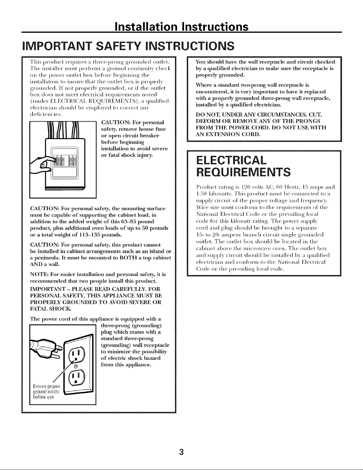
This product requires a three-prong groronled outlet.
The installer must perflmu a ground continuit_ check
on the power outlet box befl_re beginning the
installation to insm'e that the outlet box is properly
grotmded. If not properly grotmded, or if the outlet
box does not meet electrical requirements noted
(troder E1,E(_TRICAI_ REQLIIREMENTS), a qualified
electrician should be employed to correct any
deficiencies.
CAUTION: For persona]
safety, remove house fuse
or open circuit breaker
before beg_g
iusmllation to avoid severe
or fatal shock injury.
CAUTION: For personal safety, the mounting surface
must be capable of supporting the cabinet load, in
addition to the added weight of this 63-85 pound
product, plus additional oven loads of up to 50 pounds
or a total weight of 113-135 pounds.
CAUTION: For personal safety, this product cannot
be installed in cabinet arrangements such as an island or
a peninsula. It must be mounted to BOTH a top cabinet
AND a wall.
NOTE: For easier installation and personal safety, it is
recommended that two people install this product.
IMPORTANT - PLEASE READ CAREFULLY. FOR
PERSONAL SAFETY, THIS APPLIANCE MUST BE
PROPERLY GROUNDED TO AVOID SEVERE OR
FATAL SHOCK,
You should have the wall receptacle and circuit checked
by a qualified electrician to mane sure the receptacle is
properly grounded.
Where a standard two-prong wall receptacle is
encountered, it is very important to have it replaced
with a properly grounded three-prong wall receptacle,
installed by a qualified electriciaJa.
DO NOT, UNDER ANY CIRCUMSTANCES, CUT,
DI_'ORM OR REMOVE ANY OF THE PRONGS
FROM THE POWER CORD. DO NOT USE WITH
AN EXTENSION CORD.
ELECTRICAL
REQUIREMENTS
Product rating is 120 volts AC, 60 Hertz, 15 amps and
1.58 kilowatts. This product must be connected to a
supply circuit of the proper voltage and ti'equency,
Wire size must conflwm to the requirements of the
National Electrical Code or the pre\zdling local
code ti_r this kilowatt rating. The power supply
cord and plug shoMd be brought to a separate
15- to 20- ampere branch circuit single grounded
outlet, The outlet box should be located in the
cabinet above the microwave oven. The outlet box
and supply circuit should be installed by a qualified
electrician and con%tin to the National Electrical
Code or the pre\_dling local code.
The power cord of this appliance is equipped with a
tKree-prong (grounding)
plug which mates with a
standard three-prong
(grounding) wall receptacle
to minimize the possibility
of electric shock hazard
from tiffs appliance.
Ensureproper
groundexists
beforeuse
3
Installation Instructions
HOOD EXHAUST
NOTE: Read these next two pages tufty if you plan to vent your exhaust to the
outside. If you plan to recirculate the air back into the room, proceed to page 6.
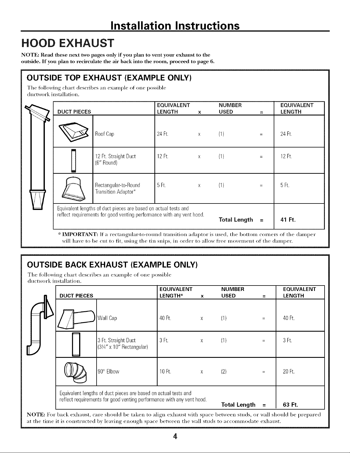
OUTSIDE TOP EXHAUST (EXAMPLE ONLY)
The following chart describes an example ot one possible
ductwork installation.
EQUIVALENT NUMBER
DUCT PIECES
12Ft.StraightDuct 12Ft. x
RoofCap 24 Ft. x
(6" Round)
-_ Rectangular-to-Round 5Ft. x
Equivalentlengthsof duct piecesare basedonactualtests and
reflectrequirementsfor goodventingperformancewith anyventhood.
* IMPORTANT: If a rectangulat_to-round transition adaptor is used, the bottom cornets of the damper
will haxe to be cut to fit, usin,,._ the tin snips, in order to allow free moxement of the damper.
TransitionAdaptor*
LENGTH x USED
OUTSIDE BACK EXHAUST (EXAMPLE ONLY)
(1)
(1)
(1)
Total Length
EQUIVALENT
LENGTH
24 Ft.
12Ft.
5Ft.
41 Ft.
The following chart describes an example ot one possible
ductwork installation.
EQUIVALENT NUMBER
LENGTH* x USED
_Wall Cap
DUC_ PIECES
[
(_ 90° Elbow
Equivalent lengths of duct piecesare based on actual tests and
reflect requirements for good venting performance with any vent hood.
NOTE: For back exhaust, care should be taken to align exhaust with space between studs, or wall should be prepared
at the time it is const_ ucted by leaving enough space between the wall studs to accommodate exhaust.
3W' x 10" Rectangular)
40Ft. x (1)
3 Ft. x (1)3 Ft.StraightDuct
10Ft. x (2)
Total Length = 63 Ft.
EQUIVALENT
LENGTH
40Ft.
3 Ft.
20Ft.
4
Installation Instructions
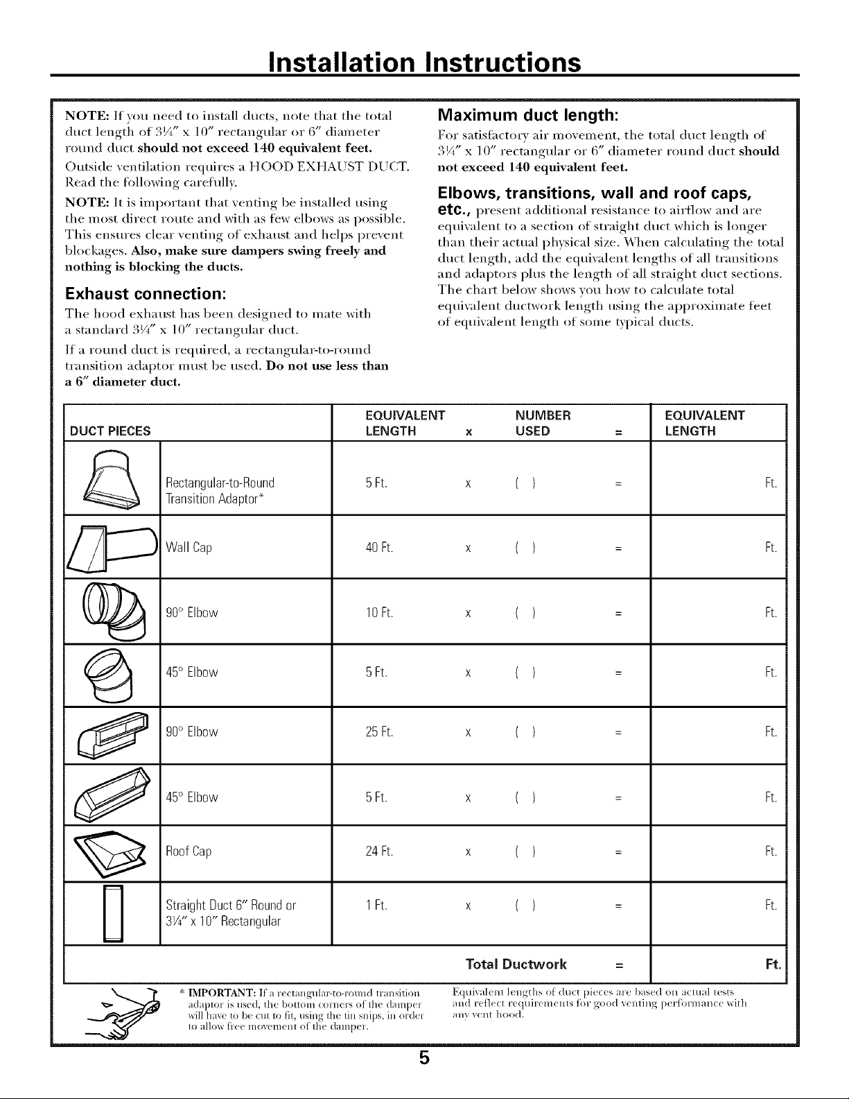
NOTE: If wm need to install ducts, note that the total
duct lengti_ of 3¼" x ] O" rectangular or 6" diameter
round duct should not exceed 140 equivalent feet.
Outside ventilation requires a HOOD EXHAUST DUCT.
Read the following careflfllv.
NOTE: It is important that venting be installed using
the most direct route and with as few elbows as possible.
This ensm'es clear venting of exhaust and helps prevent
blockages. Also, make sure dmnpers swing freely and
nothing is blocking the ducts.
Exhaust connection:
The hood exhaust has been designed to mate with
a standard 3Vt" x 10" rectangular duct.
If a round duct is required, a rectangula_to-rotmd
transition adaptor inust be used. Do not use less than
a 6" diameter duct.
EQUIVALENT NUMBER EQUIVALENT
DUCT PIECES LENGTH x USED = LENGTH
Rectangular-to-Round 5Ft. x ( ) = Ft.
TransitionAdaptor*
Maximum duct length:
For satisfiwtorv air movement, the total duct length of
3¼" x ] 0" rectangular or 6" diameter round duct should
not exceed 140 equivalent feet,
Elbows, transitions, wall and roof caps,
etc., present additional resistance to airflow and are
equiwdent to a section of straight duct which is longer
than their actual physical size. When calculating the total
duct length, add the equiwdent lengths of all transitions
and adaptors plus the length of all straight duct sections.
The chart below shows w)u how to calculate total
equivalent ductwork length using the approximate feet
of equiwdent length of some typical ducts.
..,,..,,.-%
Wall Cap 40 Ft. x ( ) = Ft.
()_ 90° Elbow 10Ft. x ( ) = Ft.
45° Elbow 5Ft. x ( ) = Ft.
90° Elbow 25Ft. x ( ) = Ft.
J 45° Elbow 5Ft. x ( ) = Ft.
RoofCap 24Ft. x ( ) = Ft.
StraightDuct6" Roundor 1Ft. x ( ) = Ft.
3W' x 10" Rectangular
Total Ductwork = Ft.
adaptor is used, the bottom comers of th( dampel and ret]ect requiremenls tk)r good venling performanc( with
xdll hax< to b< Clll to fit, using Ih(t lill snips, in ordel any vent hood.
* IMPORTANT: If a r_( tangulal_to-round transilion Equival< nl 1_ngths o[ du_t pie_<s are bas<d on aclual lests
to allm_ free lllOVelllelll of Ihe (]alllpel.
5
Installation Instructions
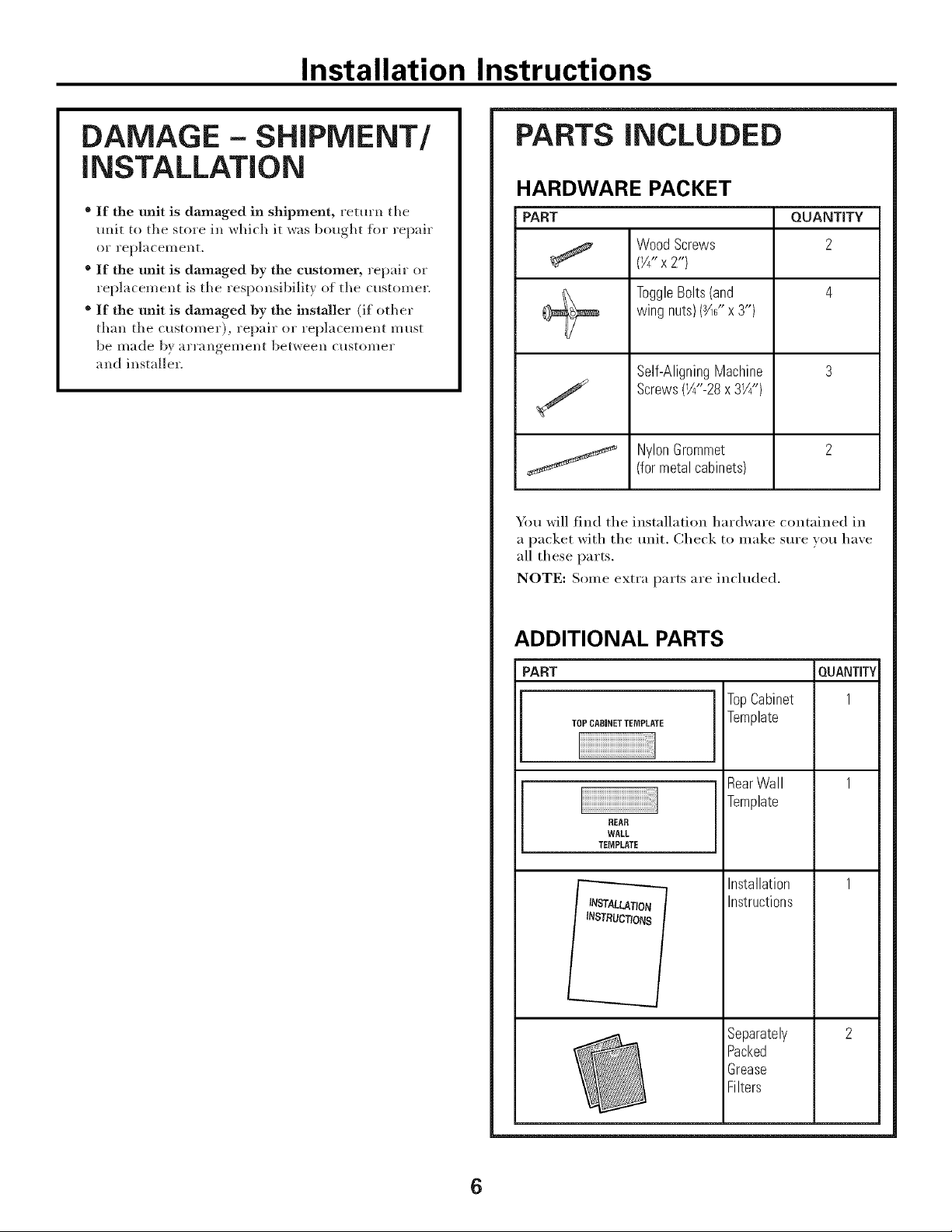
DAMAGE - SHIPMENT/
iNSTALLATiON
* If the unit is damaged in shipment, return the
unit to the store in which it was bought fin" repair
or replacement,
® If the unit is damaged by the customer, repair or
replacement is the responsibility of the customer.
® If the unit is damaged By the installer (if other
th;m the customer), repair or replacement must
be made by ;uT;mgement between customer
and installer.
PARTS iNCLUDED
HARDWARE PACKET
PART QUANTITY
Wood Screws 2
(Y4"x2")
ToggleBolts(and 4
wing nuts)(_" x 3")
Self-AligningMachine 3
Screws(W'-28x 31/4")
NylonGrommet 2
(for metal cabinets)
You will find the installation hardware contained in
a packet with the unit, Check to inake sure you have
all these parts.
NOTE: Some extI'a parts are inchlded.
ADDITIONAL PARTS
PART
TOPCABINETTEMPLATE
REAR
WALL
TEMPLATE
LATION
INSTRUCTIONS
TopCabinet
Template
RearWall
Template
Installation
Instructions
Separately
Packed
Grease
Filters
QUANTITY
1
6
Installation Instructions
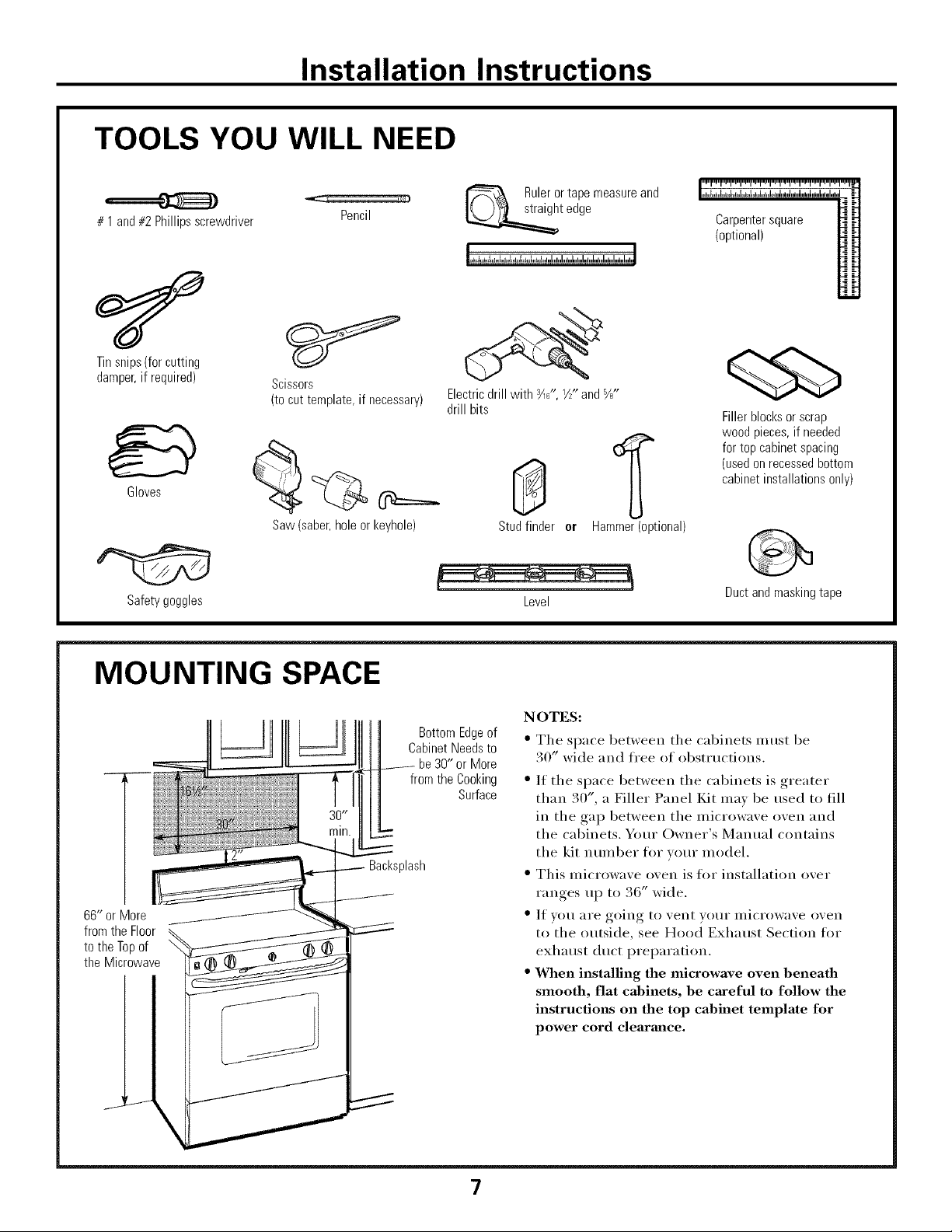
TOOLS YOU WILL NEED
# 1 and#2Phillipsscrewdriver
Tinsnips(forcutting
damper,if required)
Gloves
Scissors
(tocuttemplate,if necessary)
Pencil
Rulerortapemeasureand
t edge
Electricdrill with ¾_",V/"and%"
drill bits
(optional)
Carpentersquare
Fillerblocksor scrap
woodpieces,if needed
fortopcabinetspacing
(usedonrecessedbottom
cabinetinstallationsonly)
Saw(saber,holeor keyhole)
Safetygoggles
MOUNTING SPACE
66" or More
fromthe Floor
tothe Topof
the Microwave
BottomEdgeof
CabinetNeedsto
be30" or More
from the Cooking
Backsplash
Studfinder er Hammer(optional)
Level
NOTES:
• The space between the cabinets inust be
30" wide and fl'ee of obstructions.
Surface
• If the space between the cabinets is greater
than 30", a Filler Panel Kit may be used to fill
in the gap between the microwave oven and
the cabinets. Your Owner's Manual contains
the kit number fin" vour model.
* This microwave oven is fl)r installation over
ranges up to 36" wide.
* If VOU aye going to vent your illicrowave oven
to the outside, see Hood Exhaust Section fl)r
exhaust duct preparation.
* When installing the microwave oven beneath
smooth, flat cabinets, be careful to follow the
instructions on the top cabinet template for
power cord clearmlce.
Ductandmaskingtape
\
7
Installation Instructions
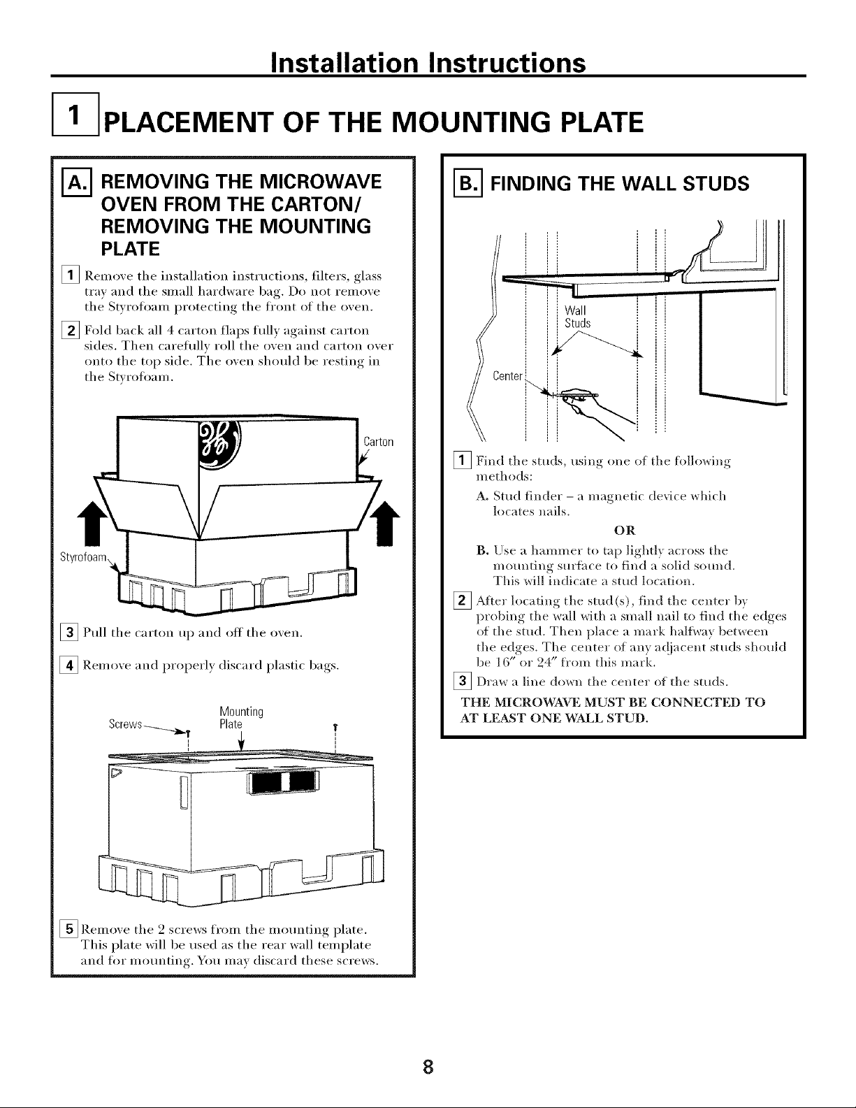
I- PLACEMENT OF THE MOUNTING PLATE
N REMOVING THE MICROWAVE
OVEN FROM THE CARTON/
REMOVING THE MOUNTING
PLATE
_ Remove the installation instructions, filters, glass
tray and the small hardware bag. Do not remove
the Swrofl)am protecting the fl'ont of the oven.
[] Fold back all 4 carton flaps flflly against carton
sides. Then careflfllv roll the oven and carton over
onto the top side. m'he oven should be resting in
the Stvrofl)am.
_Pull the carton up and off the oven.
[] Remove and properly discard plastic bags.
Mounting
Plate
!
i
N FINDING THE WALL STUDS
_ Center
_Find the studs, usino one of the followiw,
methods:
A. Stud finder - a magnetic device which
locates nails.
OR
B. Ilse a hammer to tap lightly across the
mounting surihce to find a solid s(mnd.
This will indicate a stud location.
_ After the stud find tile bylocating
probing the wall with a small nail to find the edges
of the stud. Then place a mark haltway between
the edges. Tile center of any ac!jacent studs should
be 16" or 24" fl'om this mark.
_Draw a line down the center of tile sttlds.
THE MICROWAVE MUST BE CONNECTED TO
AT LE&ST ONE WALL STUD.
(s), centel"
[]Remove the 2 screws from the mounting plate.
This plate will be used as the rear wall template
and for mounting. You max discard these screws.
8
 Loading...