

GE CVM1750SH1SS, CVM1750SH2SS, CVM1790SS1SS, CVM1790SS2SS, CVM1790SS3SS Installation Guide
...Page 1
I
stall ti
I
structi
=
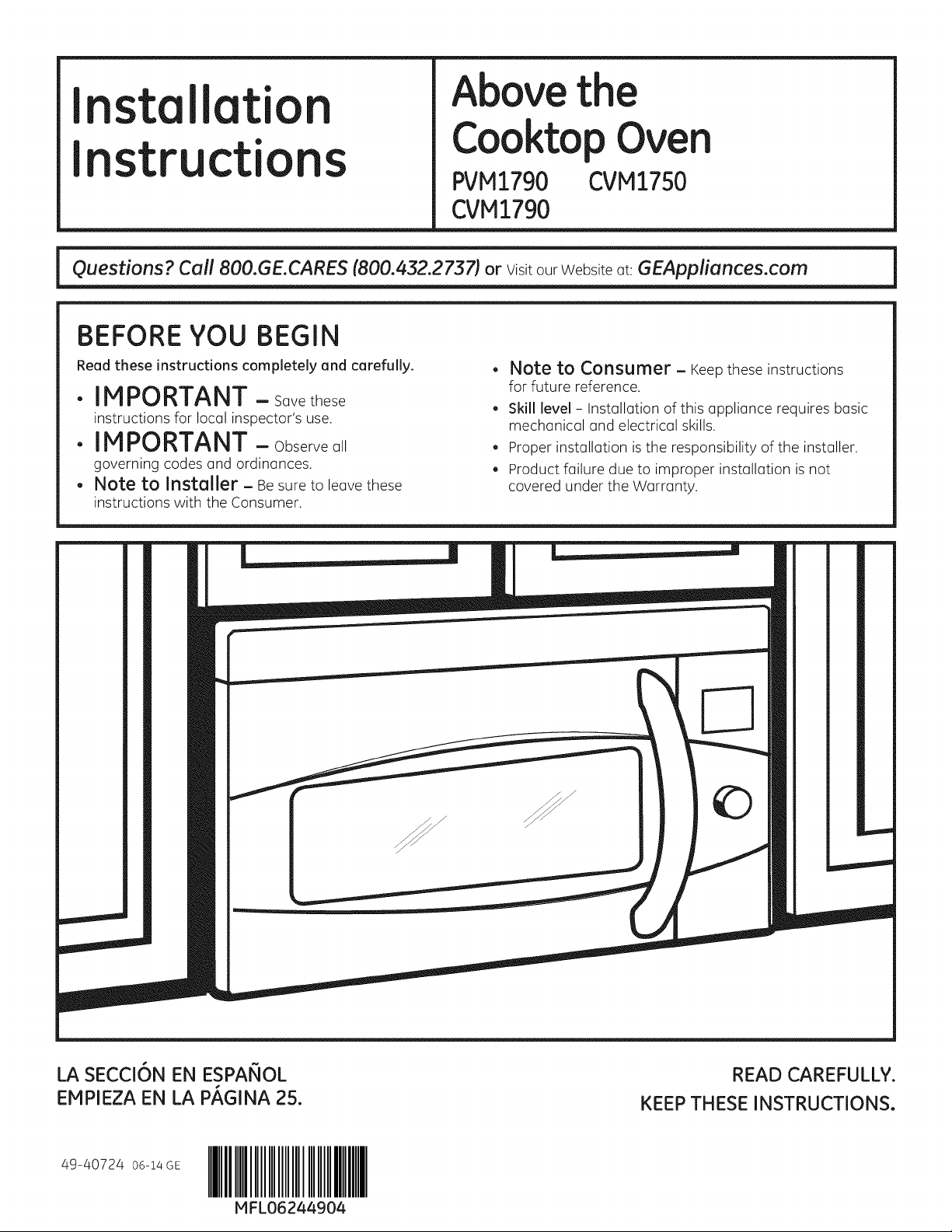
BEFORE YOU BEGIN
Above the
Cooktop Oven
PVM1790 CVM1750
CVM1790
Read these instructions completely and carefully.
.IMPORTANT -Savethese
instructionsforlocalinspector'suse.
.IMPORTANT -Observeall
governingcodesand ordinances.
. Note to Installer - Be sure to leave these
instructions with the Consumer.
Note to Consumer - Keepthese instructions
for future reference.
Skill level - Installation of this appliance requires basic
mechanical and electrical skills.
. Proper installation is the responsibility of the installer.
. Product failure due to improper installation is not
covered under the Warranty.
©
LA SECCION EN ESPANOL
EMPIEZA EN LA PAGINA 25.
49-40724 o6-14GE
IIIIIIIIIIII
MFL06244904
READ CAREFULLY.
KEEP THESE INSTRUCTIONS.
Page 2
Installation Instructions
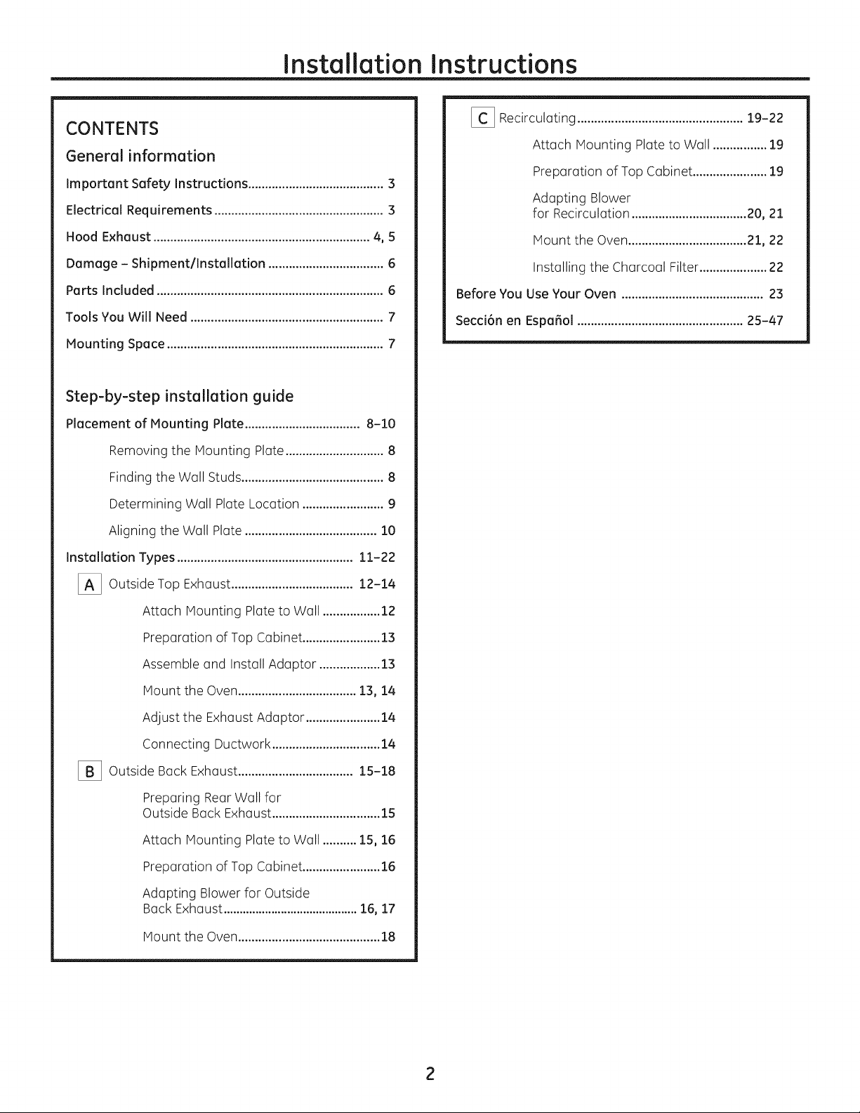
CONTENTS
General information
Important Safety Instructions ........................................ 3
Electrical Requirements .................................................. 3
Hood Exhaust ................................................................ 4, 5
Damage - Shipment/installation .................................. 6
Parts Included ................................................................... 6
Tools You Will Need ......................................................... 7
Mounting Space ................................................................ 7
Step-by-step installation guide
Placement of Mounting Plate .................................. 8-10
Removing the Mounting Plate ............................. 8
Finding the Wall Studs .......................................... 8
Determining Wall Plate Location ........................ 9
[_ Recirculating ................................................. 19-22
Attach Mounting Plate to Wall ................ 19
Preparation of Top Cabinet ...................... 19
Adapting Blower
for Recirculation .................................. 20, 21
Mount the Oven ................................... 21, 22
Installing the Charcoal Filter .................... 22
Before You Use Your Oven .......................................... 23
Secci6n en Espa_ol ................................................. 25-47
Aligning the Wall Plate ....................................... 10
Installation Types .................................................... 11-22
[_ Outside Top ....................................
[_ Outside .................................. 15-18
Exhaust 12-14
Attach Mounting Plate to Wall ................. 12
Preparation of Top Cabinet ....................... 13
Assemble and Install Adaptor .................. 13
Mount the Oven ................................... 13, 18
Adjust the Exhaust Adaptor ...................... 18
Connecting Ductwork ................................ 14
Back Exhaust
Preparing Rear Wall for
Outside Back Exhaust ................................ 15
Attach Mounting Plate to Wall .......... 15, 16
Preparation of Top Cabinet ....................... 16
Adapting Blower for Outside
Back Exhaust .......................................... 16, 17
Mount the Oven .......................................... 18
Page 3
Installation Instructions
IMPORTANT SAFETY INSTRUCTIONS
A qualified electrician must perform a ground continuity
check on the wall receptacle before beginning the
installation to ensure that the outlet box is properly
grounded. If not properly grounded, or if the wall
receptacle does not meet electrical requirements noted
(under ELECTRICALREQUIREMENTS),a qualified electrician
should be employed to correct any deficiencies.
AWARNING:
Riskof Electric Shock.
Can cause injury or death:
Remove house fuse or
open circuit breaker before
beginning installation to avoid
severe or fatal shock injury.
_VV/'_|_ l |_: Riskof Electric Shock.
Can cause injury or death: THISAPPLIANCEMUSTBE
PROPERLYGROUNDEDto avoid severe or fatal shock.
120 V Models
The power cord of this
appliance isequipped with
a three-prong (grounding}
plug which mates with
a standard three-prong
(grounding} wall receptacle
groond% s
beforeuse
to minimize the possibility
of electric shock hazard
from this appliance.
Where a standard two-prong wall receptacle is
encountered, it must be replaced with a properly
grounded three-prong wall receptacle, installed by a
qualified electrician.
AWARN ING:RiskofElectricShock.
Can cause injury or death: DO NOT,under any
circumstances, cut, deform or remove any of the prongs
from the power cord. Do not usewith an extension cord.
Failure to comply may cause fire.
A,--^! a-rl,_l
Jll_/'_lJ|| _J|_l: For personal safety, the
mounting surface must be capable of supporting the
cabinet loud, in addition to the added weight of this
63-85 pound product, plus additional oven loads of up
to 50 pounds or a total weight of 113-135 pounds.
ACAUTION: Forpersonalsafety,thisproduct
cannot be installed in cabinet arrangements such as an
island or a peninsula. It must be mounted to BOTHa top
cabinet AND awall.
IkCAUTION: Toavoidtheriskofpersonal
injury (back injury or other injuries due to excessive
weight of the microwave oven} or property damage, you
will need two people to install this microwave oven.
ELECTRICAL REQUIREMENTS
120 V Models
This product requires a three-prong grounded outlet.
Product rating is !20 volts AC, 60 Hertz, 15 amps,
and !.70 kilowatts. This product must be connected
to a supply circuit of the proper voltage and frequency.
Wire size must conform to the requirements of the
National Electrical Code or the prevailing local code
for this kilowatt rating. The power supply cord and
plug should be brought to a separate 15 to 20 ampere
branch circuit single grounded outlet. The outlet box
should be located in the cabinet above the oven and away
from any potential microwave oven ducting.The outlet
box and supply circuit should be installed by a qualified
electrician and conform to the National Electrical Code or
the prevailing local code.
3
Page 4
Installation Instructions
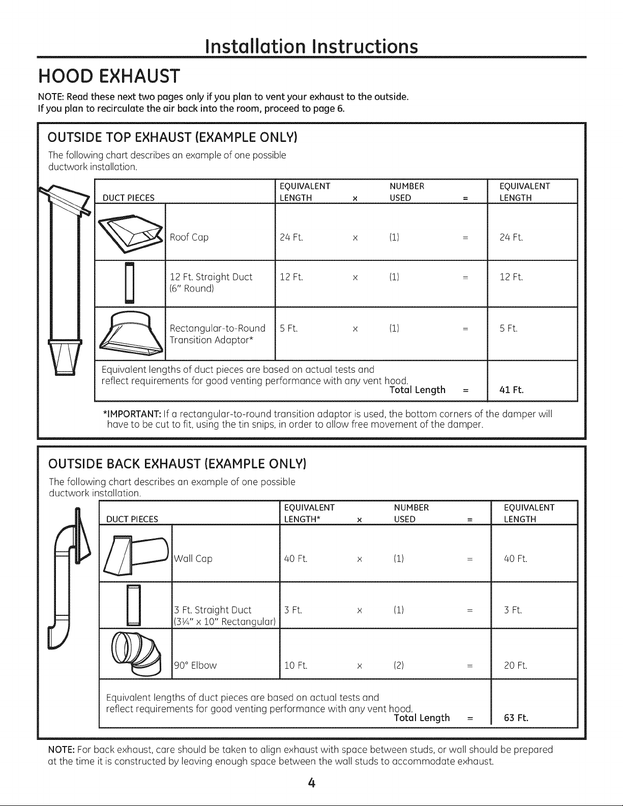
HOOD EXHAUST
NOTE:Read these next two pages only if you plan to vent your exhaust to the outside.
If you plan to redrculate the air back into the room, proceed to page 6.
OUTSIDE TOP EXHAUST (EXAMPLE ONLY)
Thefollowing chart describes an example of one possible
ductwork installation.
EQUIVALENT NUMBER EQUIVALENT
DUCT PIECES
LENGTH x USED = LENGTH
Roof Cap
!2 Ft. Straight Duct
D
Equivalent lengths of duct pieces are based on actual tests and
reflect requirements for good venting performance with any vent hood.
*IMPORTANT:Ifa rectangular-to-round transition adaptor is used, the bottom corners of the damper will
have to be cut to fit, using the tin snips, in order to allow free movement of the damper.
(6" Round)
Rectangular-to-Round
Transition Adaptor*
24 Ft. x (!)
12 Ft. x (!)
5 Ft. x (!)
OUTSIDE BACK EXHAUST (EXAMPLE ONLY)
The following chart describes an example of one possible
ductwork installation.
EQUIVALENT NUMBER EQUIVALENT
DUCT PIECES LENGTH* × USED -- LENGTH
Total Length
24 Ft.
12 Ft.
5 Ft.
41 Ft.
_ Wall Cap 40 Ft. x (!) = 40 Ft.
3 Ft. Straight Duct 3 Ft. x (!) = 3 Ft.
3¼" x i0" Rectangular)
_ 90° Elbow i0 Ft. x (2) = 20 Ft.
Equivalent lengths of duct pieces are based on actual tests and
reflect requirements for good venting performance with any vent hood.
NOTE:For back exhaust, care should be taken to align exhaust with space between studs, or wall should be prepared
at the time itis constructed by leaving enough space between the wall studs to accommodate exhaust.
Total Length = 63 Ft.
4
Page 5
Installation Instructions
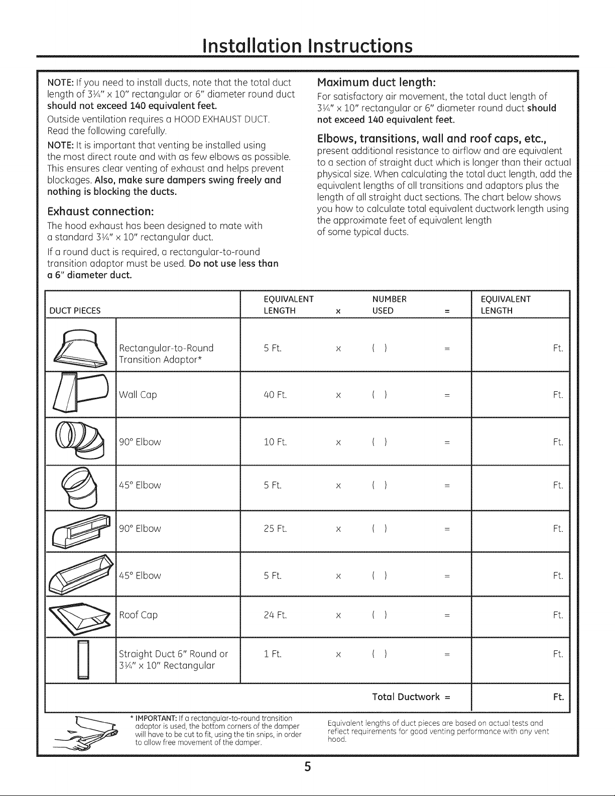
NOTE:If you need to install ducts, note that the total duct
length of 3¼" x 10" rectangular or 6" diameter round duct
should not exceed 140 equivalent feet.
Outside ventilation requires a HOODEXHAUSTDUCT.
Maximum duct length:
For satisfactory air movement, the total duct length of
3¼" x 10" rectangular or 6" diameter round duct should
not exceed 140 equivalent feet.
Reed the following carefully.
NOTE:It is important that venting be installed using
the most direct route end with as few elbows as possible.
This ensures clear venting of exhaust end helps prevent
blockages. Also, make sure dampers swing freely and
nothing is blocking the ducts.
Exhaust connection:
The hood exhaust has been designed to mate with
a standard 3½" x 10" rectangular duct.
Elbows, transitions, wall and roof caps, etc.,
present additional resistance to airflow and are equivalent
to a section of straight duct which is longer than their actual
physical size.When calculating the total duct length, add the
equivalent lengths of all transitions and adaptors plus the
length of all straight duct sections. The chart below shows
you how to calculate total equivalent ductwork length using
the approximate feet of equivalent length
of some typical ducts.
If a round duct is required, a rectangular-to-round
transition adaptor must be used. Do not use less than
a 6" diameter duct.
EQUIVALENT NUMBER EQUIVALENT
DUCT PIECES LENGTH x USED = LENGTH
Rectangular-to-Round 5 Ft. ( ) Ft.
Transition Adaptor*
x
//_ Wall Cap 40 Ft. x ( ) : Ft.
(__ 90° Elbow 10 Ft. x ( ) = Ft.
45° Elbow 5 Ft. x ( ) = Ft.
90° Elbow 25 Ft. x ( ) = Ft.
_ 45 Elbow 5Ft. x ( ) = Ft.
Roof Cap 24 Ft. x ( ) = Ft.
Straight Duct 6" Round or 1 Ft. x ( ) = Ft.
3¼" x i0"Rectangular
Total Ductwork = Ft.
adaptor is used, the bottom corners of the damper Equivalent lengths of duct pieces are based on actual tests and
will have to be cut to fit, using the tin snips, in order reflect requirements for good venting performance with any vent
* IMPORTANT:If a rectangular-to-round transition
to allow free movement of the damper, hood.
5
Page 6
Installation Instructions
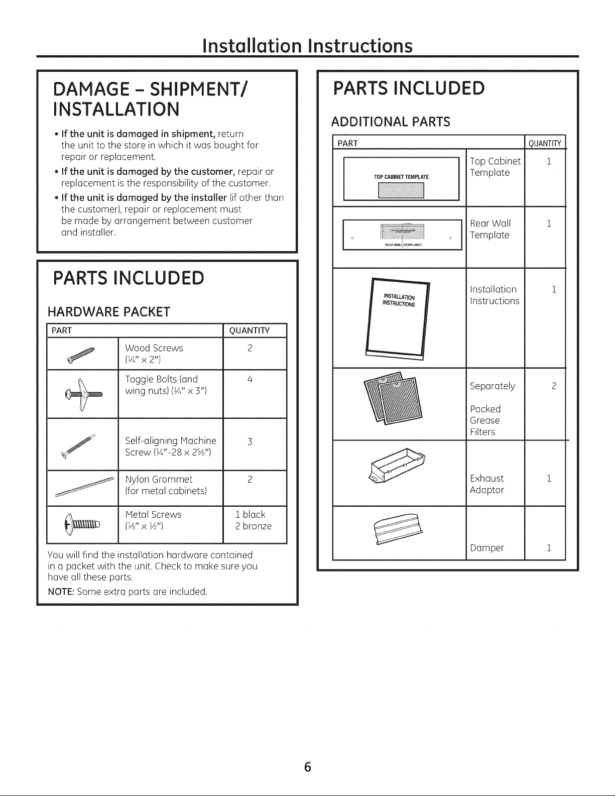
DAMAGE- SHIPMENT/
INSTALLATION
, If the unit is damaged in shipment, return
the unit to the store in which it was bought for
repair or replacement.
, If the unit is damaged by the customer, repair or
replacement is the responsibility of the customer.
, If the unit is damaged by the installer (if other than
the customer), repair or replacement must
be made by arrangement between customer
and installer.
PARTS INCLUDED
HARDWARE PACKET
PART
J
Wood Screws
(¼" x 2")
Toggle Bolts (and
wing nuts)(¼" x 3")
Self-aligning Machine
Screw (¼"-28 x 2%')
QUANTITY
2
PARTS INCLUDED
ADDITIONAL PARTS
PART
TOPCABINETTEMPLATE
INSTAU_ATION
INSTRUCTIONS
Top Cabinet
Template
RearWall
Template
Installation
Instructions
Separately
Packed
Grease
Filters
m
QUANTITY
1
Nylon Grommet
(for metal cabinets)
Metal Screws
(½" x ½")
You will find the installation hardware contained
in a packet with the unit. Check to make sure you
have all these parts.
NOTE:Some extra parts are included.
1 black
2 bronze
Exhaust
Adaptor
Damper
1
m
1
6
Page 7
Installation Instructions
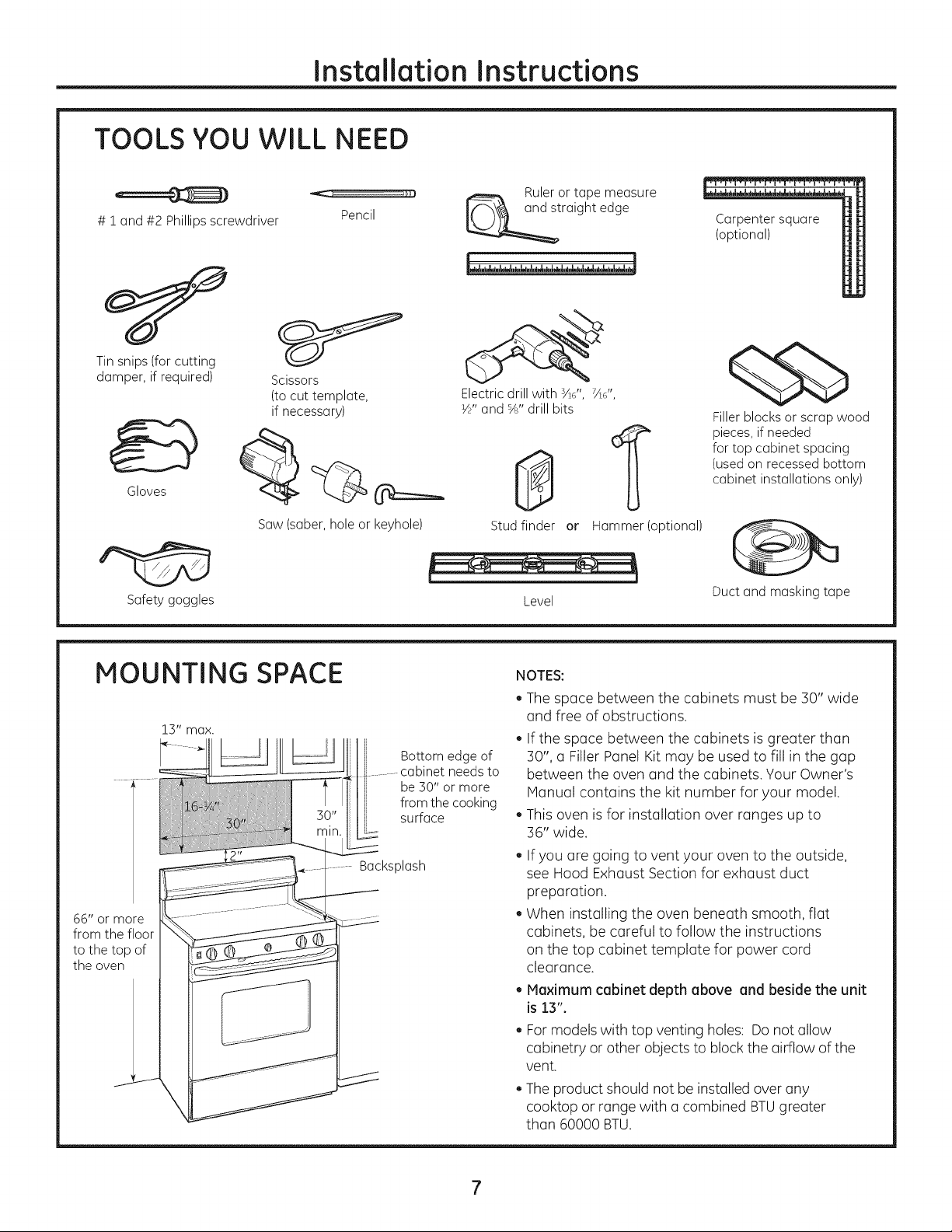
TOOLS YOU WILL NEED
# i and #2 Phillipsscrewdriver
Tinsnips(forcutting
damper,if required)
Gloves
Scissors
(to cut template,
if necessary)
Pencil
Ruleror tape measure
raightedge
Electric drill with Y/', V/',
W' and s/8"drill bits
0
1
Carpentersquare
(optional)
¢5b
Fillerblocksor scrapwood
pieces,if needed
fortop cabinetspacing
(usedon recessedbottom
cabinet installationsonly)
Saw(saber,holeor keyhole)
Safetygoggles
MOUNTING SPACE
lS" max.
66" or more
from the floor
to the top of
the oven
Bottomedgeof
cabinet needsto
be30" or more
fromthe cooking
surface
Backsplash
Studfinder or
Level
NOTES:
, The space between the cabinets must be 30" wide
and free of obstructions.
e
If the space between the cabinets is greater than
30", a Filler Panel Kit may be used to fill in the gap
between the oven and the cabinets. Your Owner's
Manual contains the kit number for your model.
This oven is for installation over ranges up to
36" wide.
, If you are going to vent your oven to the outside,
see Hood Exhaust Section for exhaust duct
preparation.
, When installing the oven beneath smooth, flat
cabinets, be careful to follow the instructions
on the top cabinet template for power cord
clearance.
. Maximum cabinet depth above and beside the unit
is 13".
, For models with top venting holes: Do not allow
cabinetry or other objects to block the airflow of the
vent.
, The product should not be installed over any
cooktop or range with a combined BTUgreater
than 60000 BTU.
Hammer(optional)
Ductand maskingtape
Page 8
Instollotion Instructions
-IPLACEMENT OF THE MOUNTING PLATE
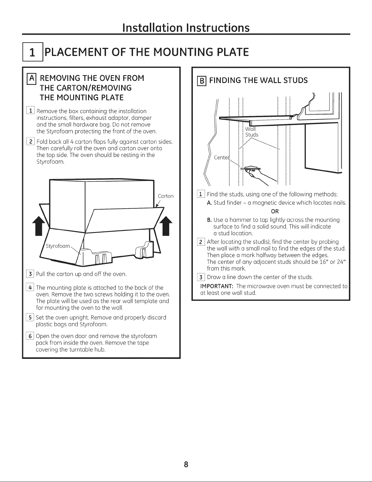
REMOVING THE OVEN FROM
THE CARTON/REMOVING
THE MOUNTING PLATE
%
Remove the box containing the installation
instructions, filters, exhaust adaptor, damper
and the small hardware bag. Do not remove
the Styrofoam protecting the front of the oven.
[]
Fold back all 4 carton flaps fully against carton sides.
Then carefully roll the oven and carton over onto
the top side.The oven should be resting in the
Styrofoam.
%
Pullthe carton up and off the oven.
%
The mounting plate is attached to the back of the
oven. Remove the two screws holding it to the oven.
The plate will be used as the rear wall template and
for mounting the oven to the wall.
%
Setthe oven upright. Remove and properly discard
plastic bags and Styrofoam.
[_ FINDING THE WALL STUDS
Wall
Studs
Cente_
[_ Findthe studs, using one of the following methods:
A. Stud finder - a magnetic device which locates nails.
OR
B. Use a hammer to tap lightly across the mounting
surface to find a solid sound. This will indicate
a stud location.
[_ After locating the stud(s),find the center by probing
the wall with a small nail to find the edges of the stud.
Then place a mark halfway between the edges.
The center of any adjacent studs should be 16" or 24"
from this mark.
[_ Draw a line down the center of the studs.
IMPORTANT: The microwave oven must be connected to
at least one wall stud.
%
Open the oven door and remove the styrofoam
pack from inside the oven. Remove the tape
covering the turntable hub.
8
Page 9

Installation Instructions
[_ DETERMINING WALL PLATE LOCATION UNDER YOUR CABINET
Plate position - beneath flat bottom
cabinet
"%
ol
At leost 30", up to 36"
MountingPlateTobs
Touchingthe CGbinet
Bottom
\
Plate position - beneath framed recessed
cabinet bottom
Mounting Plate Tabs
Touching the Bock
Frome
Plate position - beneath recessed bottom
cabinet with front overhang
Mounting Plote
with TabsBelow
CabinetBottom
the SameDistonce
osthe Front
OverhGngDepth
:
..
Your cabinets may have decorative trim that interferes
with the oven installation. Remove the decorative trim
to install the oven properly and to make it level.
THE OVEN MUST BELEVEL.
Use a level to make sure the cabinet bottom is level.
If the cabinets have a front overhang only, with no back
or side frame, install the mounting plate down the same
distance as the front overhang depth. This will keep
the oven level.
[_ Measure the inside depth of the front overhang.
[_ Draw a horizontal line on the back wall an equal
distance below the cabinet bottom as the inside depth
of the front overhang.
[_ For this type of installation with front overhang only,
align the mounting tabs with this horizontal line, not
touching the cabinet bottom as described in Step D.
30" to Cooktop
I
9
Page 10
Installation Instructions
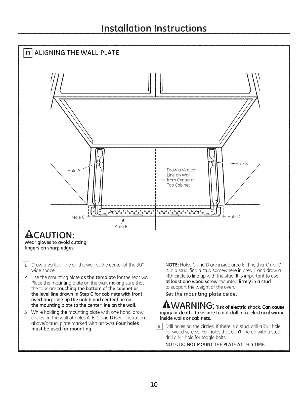
_ ALIGNING THE WALL PLATE
Hole
I
I
Hole C
4 T
AreaE J
ACAUTION'.
Wear glovestoavoidcutting
fingerson sharpedges.
[] Draw a vertical line on the wall at the center of the 30"
wide space.
[_ Usethe mounting plate as the template for the rear wall.
Placethe mounting plate on the wall, making sure that
thetabsaretouchingthebottomofthecabinetor
thelevellinedrawn inStepC forcabinetswithfront
overhang.Lineup thenotchand centerlineon
themountingplatetothecenterlineon thewall.
[_ While holding the mounting plate with one hand, draw
circles on the wall at holesA, B,Cand D(seeillustration
above/actual plate marked with arrows). Four holes
must be used for mounting.
Draw a Vertical
Line on Wall
_--- from Center of
Top Cabinet
olo
I
I
NOTE:Holes Cand D are inside area E.If neither C nor D
isin astud, find a stud somewhere in area Eand draw a
fifth circle to lineup with the stud. It is important to use
at least one wood screw mounted firmly in a stud
to support the weight of the oven.
Set the mounting plate aside.
WAR NIN G:Riskofelectricshock.Cancause
injury or death. Take care to not drill into electrical wiring
inside walls or cabinets.
[_ Drill holes on the circles. If there is a stud, drill a sad'hole
for wood screws. Forholes that don't line up with a stud,
drill a %" hole for toggle bolts.
NOTE:DONOTMOUNTTHEPLATEATTHISTIME.
10
Page 11
Installation Instructions
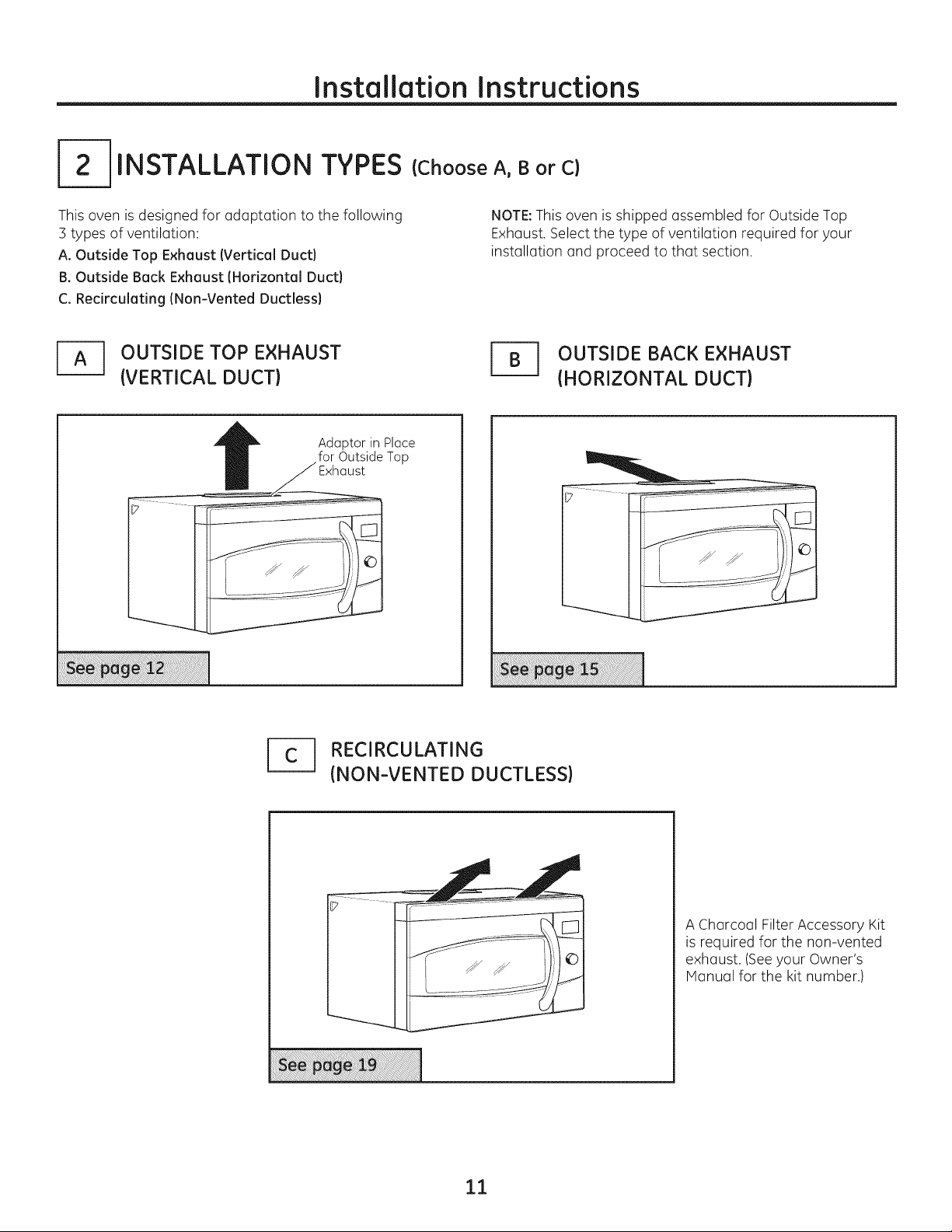
INSTALLATION TYPES
This oven is designed for adaptation to the following
3 types of ventilation:
A. Outside Top Exhaust (Vertical Duct}
B. Outside Back Exhaust (Horizontal Duct}
C. Recirculating (Non-Vented Ductless}
OUTSIDE TOP EXHAUST
(VERTICAL DUCT)
Adaptor in Place
for Outside Top
(Choose A, B or C)
NOTE:This oven is shipped assembled for Outside Top
Exhaust. Select the type of ventilation required for your
installation and proceed to that section.
r_ UTSIDE BACK EXHAUST
(HORIZONTAL DUCT)
1_ RECIRCULATING
(NON-VENTED DUCTLESS)
A Charcoal FilterAccessory Kit
is required for the non-vented
exhaust. (Seeyour Owner's
Manual for the kit number.)
11
Page 12
Installation Instructions
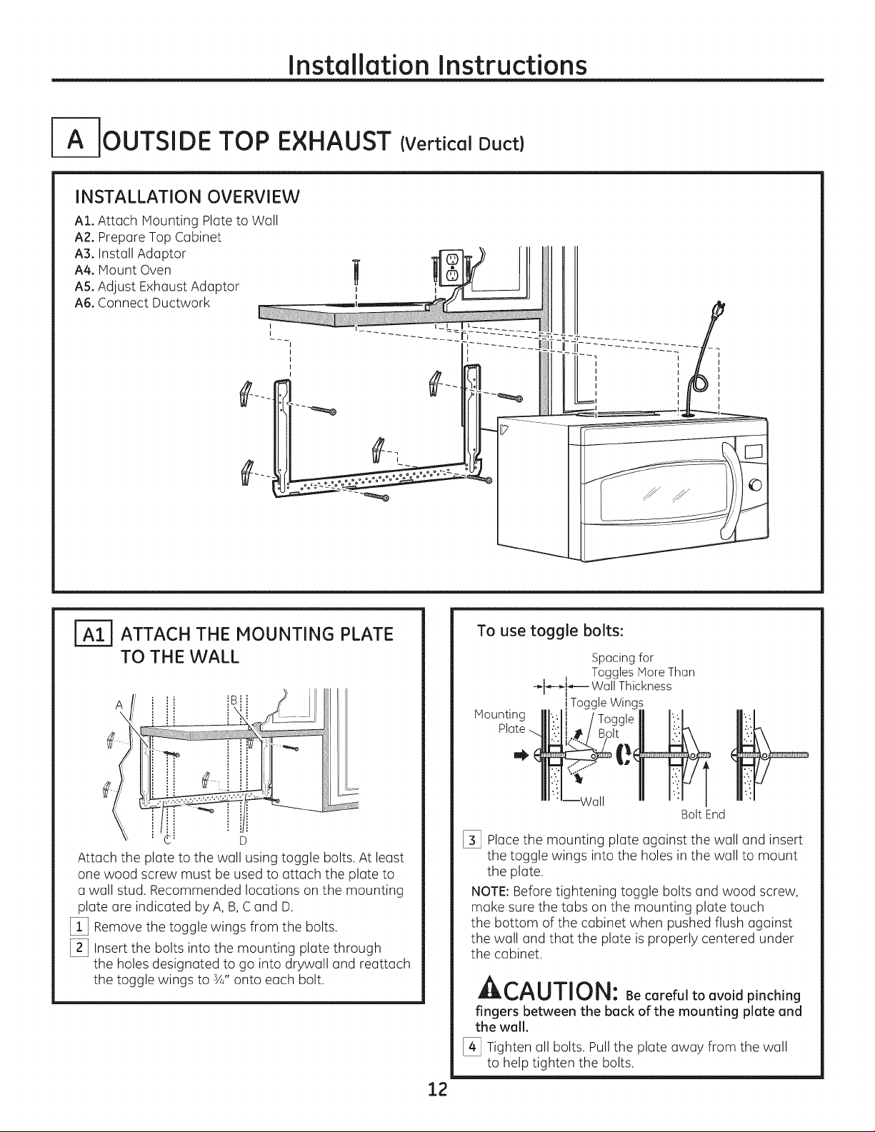
_OUTSIDE TOP EXHAUST (Vertical Duct)
INSTALLATION OVERVIEW
AI. Attach Mounting Plate to Wall
A2. Prepare Top Cabinet
A3. Install Adaptor _ _FAq_)> II Ill
A4.MountOven tl nU_IV I1I_II
A5. Adjust Exhaust Adaptor ? i_--_q-- Jl Ill
A6. ConnectDuctwork --I " l f
" I L"
_TI ATTACH THE MOUNTING PLATE
TO THE WALL
A _B!i
=_
¢_ D
Attach the plate to the wall using toggle bolts. At least
one wood screw must be used to attach the plate to
a wall stud. Recommended locations on the mounting
plate are indicated by A, B,C and D.
[_ Remove the toggle wings from the bolts.
[_ Insert the bolts into the mounting plate through
the holes designated to go into drywall and reattach
the toggle wings to ¾" onto each bolt.
To use toggle bolts:
Spacingfor
-__Hq_--- WallThickness
' I
Mounting
[_ Place the mounting plate against the wall and insert
the toggle wings into the holes in the wall to mount
the plate.
NOTE:Before tightening toggle bolts and wood screw,
make sure the tabs on the mounting plate touch
the bottom of the cabinet when pushed flush against
the wall and that the plate is properly centered under
the cabinet.
Toggles More Than
!ToggleWings
Bolt End
At,^, ,-,-,r,,_,
J;i,l_,l"_Ull11J|_l: Becareful to avoid pinching
fingers between the back of the mounting plate and
the wall.
[_ Tighten all bolts. Pull the plate away from the wall
to help tighten the bolts.
12
Page 13
Installation Instructions
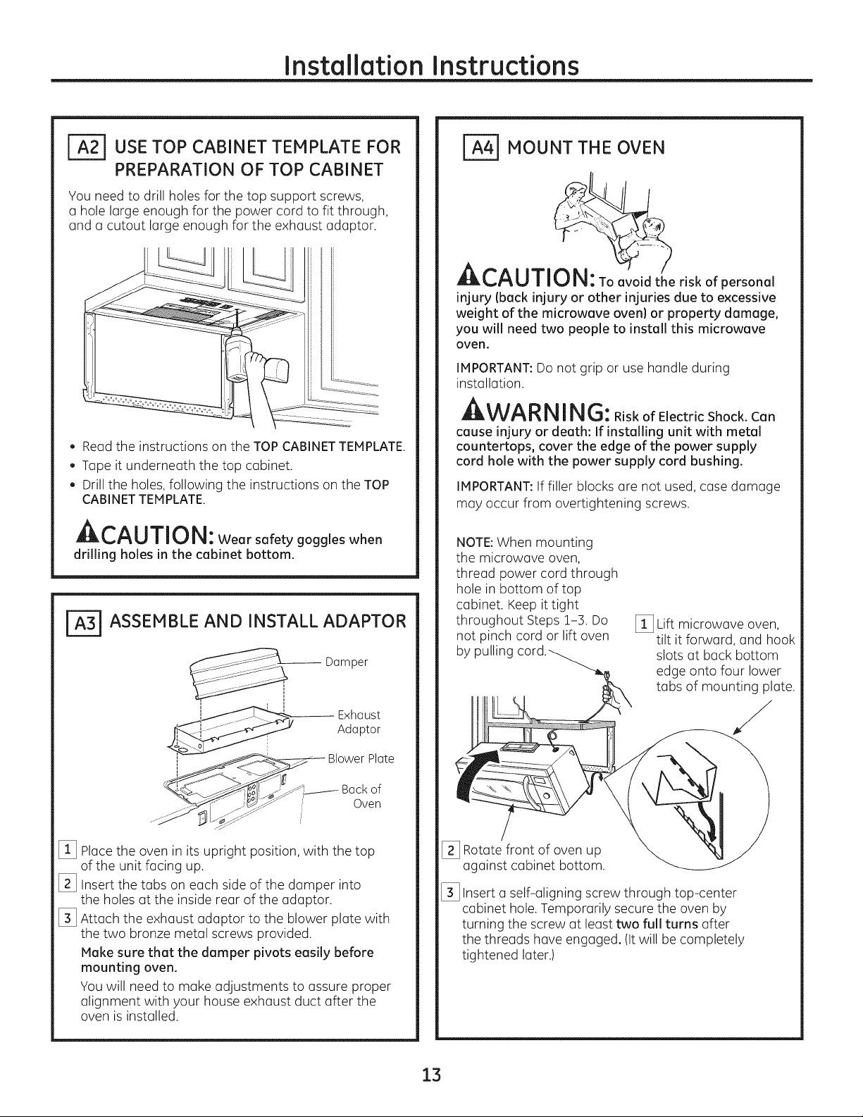
USE TOP CABINET TEMPLATE FOR
PREPARATION OF TOP CABINET
You need to drill holes for the top support screws,
a hole large enough for the power cord to fit through,
and a cutout large enough for the exhaust adaptor.
. Read the instructions on the TOP CABINET TEMPLATE.
. Tape it underneath the top cabinet.
. Drill the holes, following the instructions on the TOP
CABINET TEMPLATE.
A,-,^a l-ri,-,_a
LIL_I'_U|IIJ|_i: Wear safety goggles when
drilling holes in the cabinet bottom.
r_ ASSEMBLE AND INSTALL ADAPTOR
Damper
_ MOUNT THE OVEN
CAUTI'ON:Toavo riskofpersonal
injury (back injury or other injuries due to excessive
weight of the microwave oven) or property damage,
you will need two people to install this microwave
oven.
IMPORTANT:Do not grip or use handle during
installation.
WARNING:RiskofElectricShock.Can
cause injury or death: If installing unit with metal
countertops, cover the edge of the power supply
cord hole with the power supply cord bushing.
IMPORTANT:If filler blocks are not used, case damage
may occur from overtightening screws.
NOTE:When mounting
the microwave oven,
thread power cord through
hole in bottom of top
cabinet. Keep it tight
throughout Steps 1-3. Do
not pinch cord or lift oven
by pulling
[_ Lift microwave oven,
tilt it forward, and hook
slots at back bottom
edge onto four lower
tabs of mounting plate.
,t----i ...... Exhaust
i
i ___BI°wer Plate
l__ _--_iF ' Backof
[_ Placethe oven in its upright position, with the top
of the unit facing up.
[_ Insert the tabs on each side of the damper into
the holes at the inside rear of the adaptor.
[_ Attach the exhaust adaptor to the blower plate with
the two bronze metal screws provided.
Make sure that the damper pivots easily before
mounting oven.
You will need to make adjustments to assure proper
alignment with your house exhaust duct after the
oven is installed.
Adaptor
Oven
[_ Rotate front of oven up
against cabinet bottom.
[_ Insert a self-aligning screw through top-center
cabinet hole. Temporarily secure the oven by
turning the screw at least two full turns after
the threads have engaged. (It will be completely
tightened later.)
13
Page 14
Installation Instructions
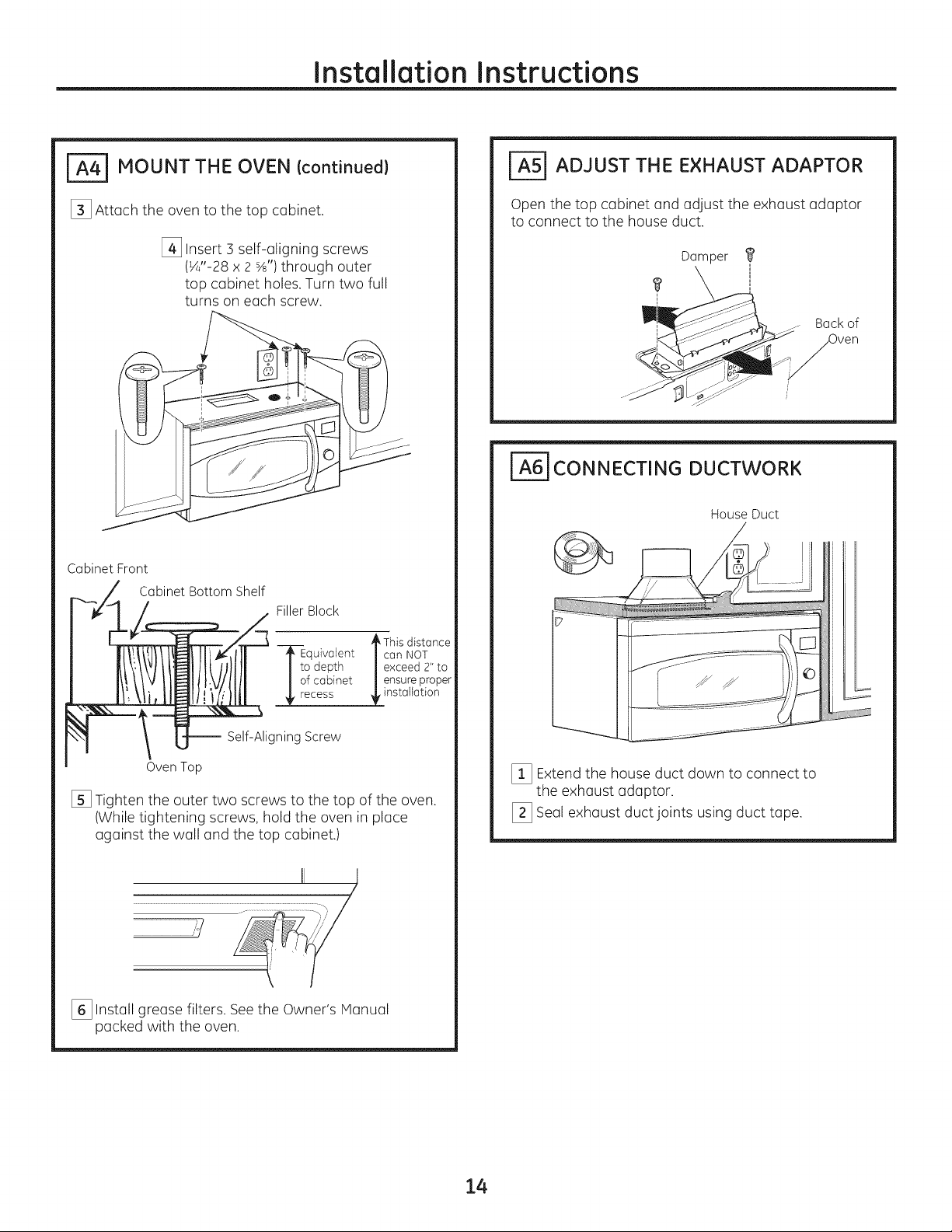
_ MOUNT THE OVEN (continued)
[_ Attach the oven to the top cabinet.
[_ Insert 3 self-aligning screws
(¼"-28 x 2 S/s")through outer
top cabinet holes. Turn two full
turns on each screw.
Cabinet Front
Cabinet Bottom Shelf
FillerBlock
_=5] ADJUST THE EXHAUST ADAPTOR
Open the top cabinet and adjust the exhaust adaptor
to connect to the house duct.
Damper
i ,_
_q - Backof
i_J _ _ L.3_/_ ,Oven
_6] CONNECTING DUCTWORK
House Duct
._E ° _, This distance
quivalent |can NOT
o depth | exceed 2" to
f cabinet | ensure proper
_installation
-- Self-Aligning Screw
Oven Top
[] Tighten the outer two screws to the top of the oven.
(While tightening screws, hold the oven in place
against the wall and the top cabinet.)
..............................................................................................111 i _],
[_ Install grease filters. Seethe Owner's Manual
packed with the oven.
,/
[_ Extend the house duct down to connect to
the exhaust adaptor.
[_ Seal exhaust duct joints using duct tape.
14
Page 15
Installation Instructions
a-- OUTSIDE BACK EXHAUST (Horizontal Duct)
INSTALLATION OVERVIEW
B1. Prepare Rear Wall
B2.Attach Mounting Plate to Wall
B3. Prepare Top Cabinet
B4.Adjust Blower
B5. Mount the Oven
I
I
I
_ PREPARING THE REAR WALL
FOR OUTSIDE BACK EXHAUST
You need to cut an opening in the rear wall for outside
exhaust.
, Readthe instructions on the REARWALL TEMPLATE.
, Tape it to the rear wall, lining up with the holes
previously drilled for holes A and B inthe wall plate.
, Cut the opening, following the instructions of the
REARWALL TEMPLATE.
ATTACH THE MOUNTING PLATE
TO THE WALL
Attach the plate to the wall using toggle bolts. At least
one wood screw must be used to attach the plate to
a wall stud.
[_ Remove the toggle wings from the bolts.
[_ Insert the bolts into the mounting plate through
the holes designated to go into drywall and reattach
the toggle wings to sA"onto each bolt.
15
Page 16

Installation Instructions
To use toggle bolts:
Spacing for Toggles More
-_l-_-_----Than Wall Thickness
Mounting Toggle Wings
Platemj__"
Bolt End
[_ Placethe mounting plate against the wall and insert
the toggle wings into the holes in the wall to mount
the plate.
NOTE:Before tightening toggle bolts and wood screw,
make sure the tabs on the mounting plate touch
the bottom of the cabinet when pushed flush against
the wall and that the plate is properly centered under
the cabinet.
CAUTI0 N:Be carefultoavoidpinching
fingersbetweenthe back ofthemounting
plateand thewall.
[_ Tighten all bolts. Pull the plate away from the wall
to help tighten the bolts.
__ ADAPTING BLOWER FOR
OUTSIDE BACK EXHAUST
[_ Remove the three screws that hold the blower
plate to the oven. Slide blower plate from under
its retaining flange. Remove and save the screw
that holds blower motor to oven.
t_
Retaining _ _i!_<_
Flange._. __-_-- BlowerPlate
__ Blower
.-"-_ -_i-_ MotorScrew
[_ Carefully pull out the blower unit. Thewires
will extend far enough to allow you to adjust
the blower unit.
End
r-_ USE TOP CABINET TEMPLATE
FOR PREPARATION OF TOP
CABINET
You need to drill holes for the top support screws and
a hole large enough for the power cord to fit through.
, Read the instructions on the TOP CABINET
TEMPLATE.
, Tape it underneath the top cabinet.
, Drill the holes, following the instructions on the
TOP CABINET TEMPLATE.
CAUTION: Wearsafety goggles when
drilling holes in the cabinet bottom.
[_ Rotate blower unit counterclockwise 180°.
Before Rotation After Rotation
Back of
Oven Oven
[_ Gently remove the wires from the grooves,
Reroute the wires through grooves on other side
of the blower unit.
Before Rerouting After Rerouting
Wires Routed Through Right
Side
Wires RoutedThroughLeft
Side
3ack of
16
Page 17
Installation Instructions
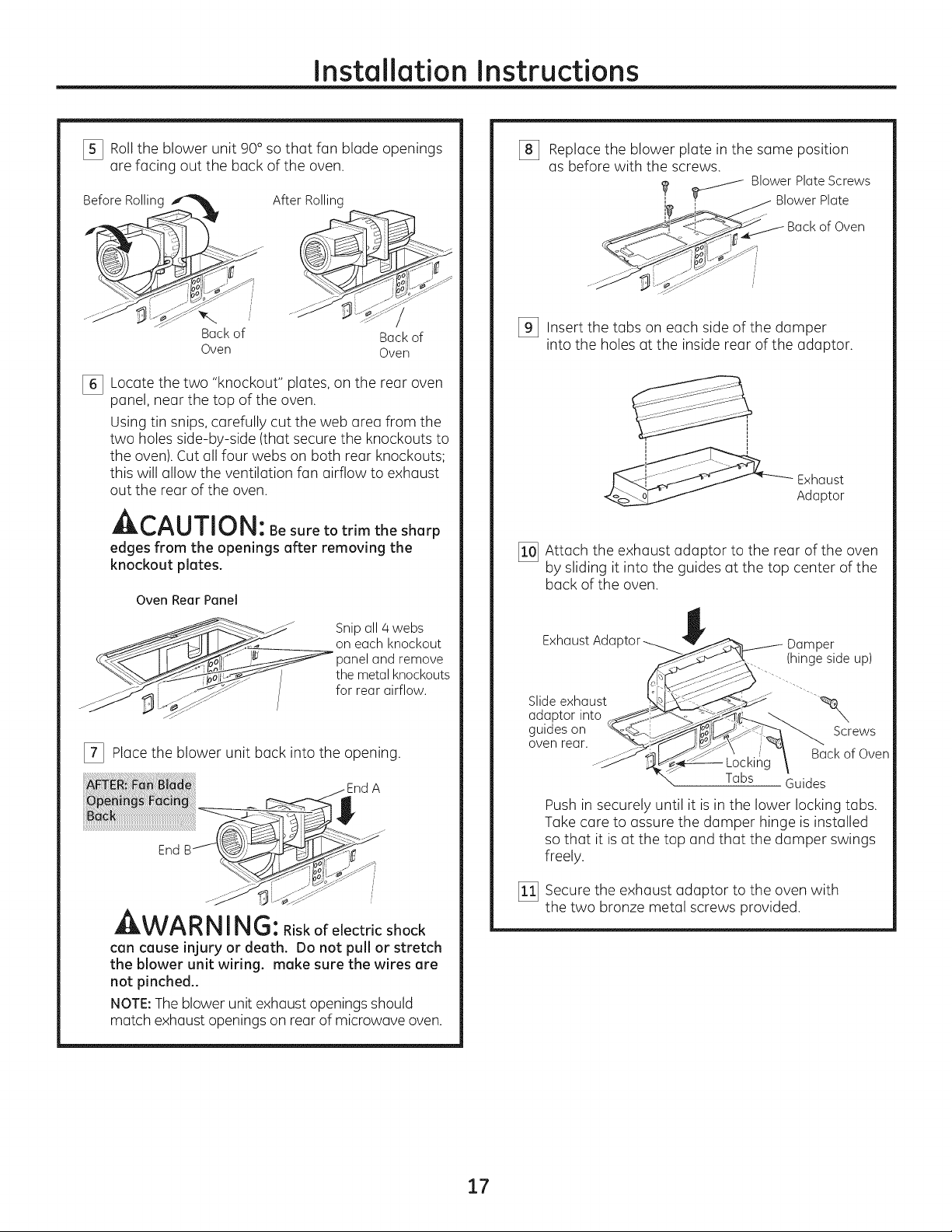
I_ Roll the blower unit 90° so that fan blade openings
are facing out the back of the oven.
BeforeRolling
Backof
Oven
Locate the two "knockout" plates, on the rear oven
%
panel, near the top of the oven.
Using tin snips, carefully cut the web area from the
two holes side-by-side (that secure the knockouts to
the oven). Cut all four webs on both rear knockouts;
this will allow the ventilation fan airflow to exhaust
out the rear of the oven.
After Rolling
Back of
Oven
A,--^l I-rl,- m
Jlbt'_U|| _-.Jl_l: Besure to trim the sharp
edges from the openings after removing the
knockout plates.
Oven Rear Panel
Replace the blower plate in the same position
%
as before with the screws.
_ BlowerPlateScrews
_J _c!O__ BackofOven
[_ Insert the tabs on each side of the damper
into the holes at the inside rear of the adaptor.
[_ Attach the exhaust adaptor to the rear of the oven
by sliding it into the guides at the top center of the
back of the oven.
BlowerPlate
--- Exhaust
Adaptor
Snipall/4webs
on each knockout
paneland remove
"_.___ the metalknockouts
_;-- _._" forrearairflow.
[_ Place the blower unit back into the opening.
A
End
WA RNING:Riskofelectricshock
can cause injury or death. Do not pull or stretch
the blower unit wiring, make sure the wires are
not pinched..
NOTE:The blower unit exhaust openings should
match exhaust openings on rear of microwave oven.
Exhaust Aria
Slide exhaust
adaptor into
guides on
oven rear.
Locking
Tabs Guides
Push in securely until it is in the lower locking tabs.
Take care to assure the damper hinge is installed
so that it is at the top and that the damper swings
freely.
[_ Secure the exhaust adaptor to the oven with
the two bronze metal screws provided.
Damper
(hingesideup)
Back of Oven
Screws
17
Page 18
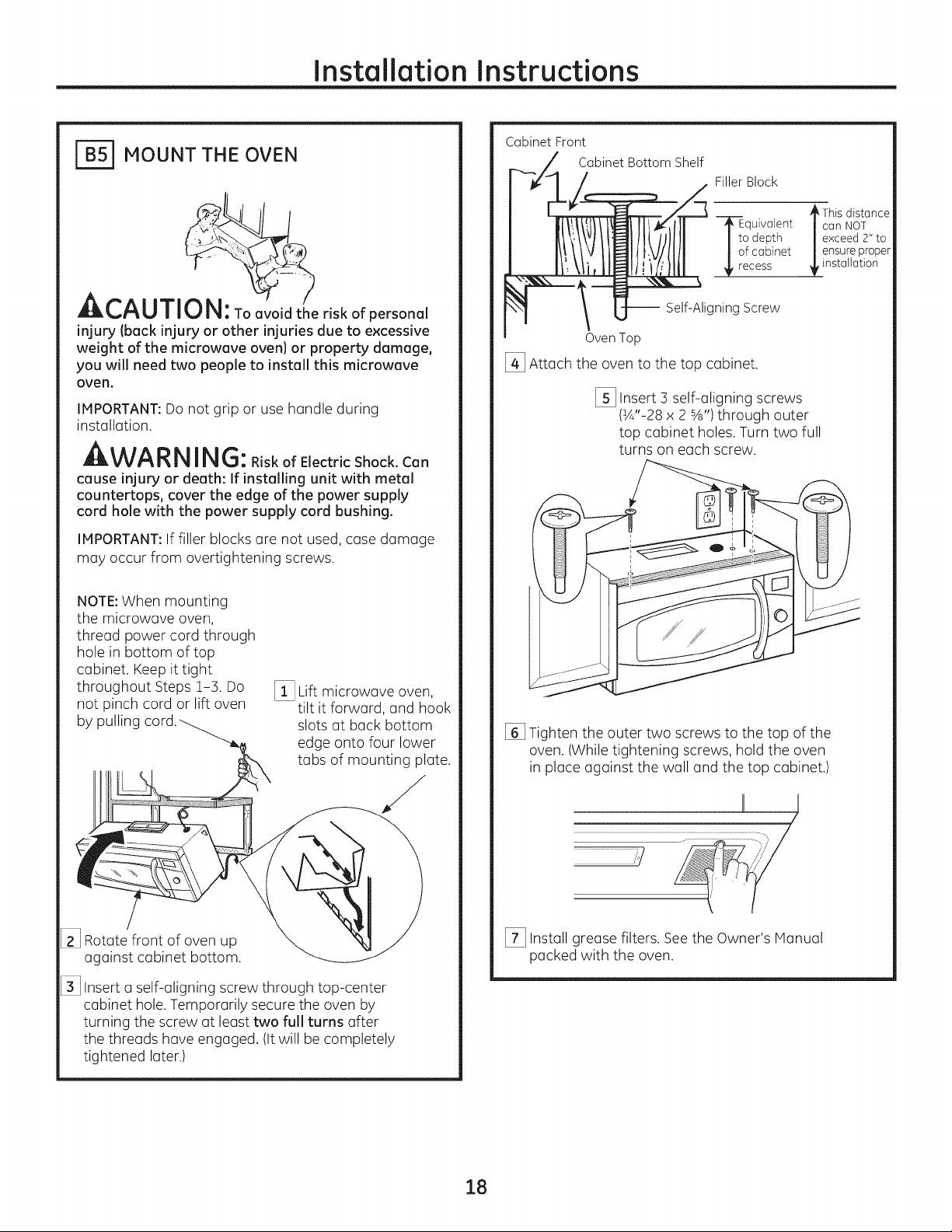
[_ MOUNT THE OVEN
Installation Instructions
Cabinet Front
Cabinet Bottom Shelf
Filler Block
ACAUTION: To°voidtheriskofpersonal
injury (back injury or other injuries due to excessive
weight of the microwave oven) or property damage,
you will need two people to install this microwave
oven.
IMPORTANT:Do not grip or use handle during
installation.
WARN ING: RiskofElectricShock.Can
cause injury or death: If installing unit with metal
countertops, cover the edge of the power supply
cord hole with the power supply cord bushing.
IMPORTANT:If filler blocks are not used, case damage
may occur from overtightening screws.
NOTE:When mounting
the microwave oven,
thread power cord through
hole in bottom of top
cabinet. Keep it tight
throughout Steps 1-3. Do
not pinch cord or lift oven
by pulling
[_ Lift microwave oven,
tilt it forward, and hook
slots at back bottom
edge onto four lower
tabs of mounting plate.
-_rtoEequivale nt
o depth
f cabinet
cess
-- Self-Aligning Screw
Oven Top
[_ Attach the oven to the top cabinet.
[_ Insert 3 self-aligning screws
(½"-28 x 2 %') through outer
top cabinet holes. Turn two full
turns on each screw.
[] Tighten the outer two screws to the top of the
oven. (While tightening screws, hold the oven
in place against the wall and the top cabinet.)
This distance
can NOT
exceed 2" to
ensure proper
installation
[_ Rotate front of oven up
against cabinet bottom.
[_ Insert a self-aligning screw through top-center
cabinet hole. Temporarily secure the oven by
turning the screw at least two full turns after
the threads have engaged. (It will be completely
tightened later.)
ii j
....................................................._ .......................
[_ Install grease filters. Seethe Owner's Hanual
packed with the oven.
18
Page 19

Installation Instructions
-- RECIRCULATING (Non-Vented Ductless}
INSTALLATION OVERVIEW
C1. Attach Mounting Plate to Wall
C2. Prepare Top Cabinet
C3. Adjust Blower
Ca,.Mount the Oven
CE Install Charcoal Filter (not suppliedt
I
I
I
ATTACH THE MOUNTING PLATE
TO TH E WALL
, ,> i i !i i
Attach the plate to the wall using toggle bolts. At least
one wood screw must be used to attach the plate to
a wall stud.
[] Remove the toggle wings from the bolts.
[_ Insert the bolts into the mounting plate through
the holes designated to go into drywall and reattach
the toggle wings to ¾" onto each bolt.
To use toggle bolts:
Spacingfor
TogglesMoreThan
-_1-_-__----WallThickness
iToggleWings
Mounting
[_ Place the mounting plate against the wall and insert
the toggle wings into the holes in the wall to mount
the plate.
NOTE:Before tightening toggle bolts and wood screw,
make sure the tabs on the mounting plate touch the
bottom of the cabinet when pushed flush against the
wall and that the plate is properly centered under the
cabinet.
A,--^l ,-rl_l,i
LII, I_,I"_I,,IIIILJ I_I: Be careful to avoid pinching
fingers between the beck of the mounting plete end
the well.
[_ Tighten all bolts, Pull the plate away from the wall
to help tighten the bolts.
_--_ USETOPCABINETTEHPLATE
FORPREPARATIONOF TOPCABINET
You need to drill holes for the top support screws and
a hole large enough for the power cord to fit through.
, Read the instructions on the TOP CABINET
TEMPLATE.
, Tape it underneath the top cabinet.
, Drill the holes, following the instructions on the TOP
CABINET TEMPLATE.
BoltEnd
A,-,^, ,-r,,-_ _,
mrm'_,l=_U||11J |_ : Weer sefety goggles when
drilling holes in the cebinet bottom.
19
Page 20

Installation Instructions
ADAPTING BLOWER
FOR RECIRCULATION
NOTE:The exhaust adaptor with damper is not
needed for recirculating models. You may want
to save them for possible future use.
[_ Remove and save screws that hold blower plate
to the oven.
_,V _ BlowerPlateScrews
------ Backof
Oven
[_ Slide the blower plate from under its retaining
flange and lift it off. Remove and save screw that
holds the blower motor to oven.
Retaining _q_l_,_
Hang ___ Blower Plate
[_ Carefully pull out the blower unit. The wires
will extend far enough to allow you to adjust
the blower unit.
[_ Rollthe blower unit 90° so that fan blade openings
are facing toward the front of the oven.
Roll
__ Blower
Motor Screw
/ Jl /J"
/
NOTE:Make sure wires remain routed in the grooves
of the motor frame.
2O
Page 21

Installation Instructions
_ ADAPTING BLOWER FOR
RECIRCULATION Icontinued)
[_ Place the blower unit back into the opening.
_WARN ING: Riskofelectricshock
can cause injury or death. Do not pull or stretch
the blower unit wiring. Make sure the wired are
not pinched.
[_ Secure blower unit to oven with the 2
removed in Step 2. Insert the screw in bottom right
screw hole on the back of the oven.
[_ Reploce blower plate with the screws removed in
Step 1.
,_ _ BlowerPloteScrews
screws
[_ MOUNT THE OVEN
A.--^.,-r,_ _,
klLk.,/_U/IU |_1: TOavoid the risk of personal
injury (back injury or other injuries due to excessive
weight of the microwave oven) or property damage,
you will need two people to install this microwave
oven.
IMPORTANT:Do not grip or use handle during
installation.
WA RNING:RiskofElectricShock.Can
cause injury or death: If installing unit with metal
countertops, cover the edge of the power supply
cord hole with the power supply cord bushing.
IMPORTANT:If filler blocks (]re not used,case damage
may occur from overtightening screws.
...._ _ L_" -_-"" Blower Motor
Bockof Oven
Screw
NOTE:When mounting
the microwave oven,
thread power cord through
hole in bottom of top
cabinet. Keep it tight
throughout Steps 1-3. Do
not pinch cord or lift oven
by pulling
[_ Rotate front of oven up
against cabinet bottom.
[_ Lift microwave oven,
tilt it forward, and hook
slots at back bottom
edge onto four lower
tabs of mounting plate.
21
Page 22

Installation Instructions
MOUNT THE OVEN (continuedl
[_ Insert a self-aligning screw through top-center
cabinet hole. Temporarily secure the oven by
turning the screw at least two full turns after
the threads have engaged. (It will be completely
tightened later.)
Cabinet Front
Cabinet Bottom Shelf
Filler Block
J_o E _ This distance
quivaJent |can NOT
o depth | exceed 2" to
f cabinet /ensurepr°per
_installation
-- Self-Aligning Screw
Oven Top
[_ Insert 3 self-aligning screws
(½"-28 x 2%") through outer
top cabinet holes. Turn two full
turns on each screw.
IC51 INSTALLING THE CHARCOAL
FILTER
[_ Remove 2 screws on top of oven,just above
the grille panel, using a Phillips screwdriver.
[_ Open the door.
[_ Remove the grille.
I
Screws
f
J
Grille
[_ Insert the filter into the oven us shown until it fits
squarely into place. It will rest at an angle behind
the front lower tabs. When properly installed,
the wire mesh of the filter should be visible
from the front.
[] Tighten the outer two screws to the top of the
oven. (Whiletightening screws, hold the oven
in place against the wall and the top cabinet.)
II t
_/
//
[_ Install grease filters. See the Owner's Manual
packed with the oven.
Frontlowertabs
J
J
Charcoal filter
I_ Replace the grille and the 2 top screws.
[_ Close the door and replace left side screw.
22
Page 23

Installation Instructions
BEFORE YOU USE YOUR OVEN
Make sure the oven has been installed
according to instructions.
r_ Remove all packing material from the oven.
[_] Read the Owner's Manual.
KEEP INSTALLATION INSTRUCTIONS
FOR THE LOCAL INSPECTOR'S USE.
_ Replace house fuse or turn breaker back on.
F_ 120 V Models: Plug power cord into
a dedicated !5- to 20-amp electrical outlet.
Ensure proper
ground exists
before use.
Where a standard two-prong wall receptacle
is encountered, it is very important to have it
replaced with a properly grounded three-prong
wall receptacle, installed by a qualified
electrician.
23
Page 24

49-40724
HFL06244904
(06-14 GE)
Printed in Korea
24
Page 25

I strucci
de i stal
i
ANTES DE EMPEZAR
Homo para colocar
encima de la estufa
PVM1790 CVM1750
CVM1790
Lea estas instrucciones complet° y cuidadosamente.
. IMPORTANTE - Guardeestas
instrucciones par° el uso clel inspector local.
. IMPORTANTE - Cump,acontodos,os
c6digos y orclenonzes gubernamentales.
. Not° par° el instalador - Aseg0resede dejer
estas instrucciones con el consumidor.
, Not° par° el consumJdor - Guarde estas
instrucciones para futura referenciu.
, Nivel de destrezas - Lu instuluci6n de este apuruto
requiere de destrezas b6sicas de mecc_nicay electricidad.
, Lu instulaci6n apropiada es responsubilidad
del instaludor.
La falla del producto debido a una instalaci6n
inapropiada no est6 cubierta por la garant[a.
©
25
LEA CUIDADOSAMENTE.
GUARDE ESTAS INSTRUCCIONES.
Page 26
Instruccionesde instalaci6n
CONTENIDO
Informaci6n general
Instrucciones de seguridad importantes ................... 27
Requisitos el_ctricos ...................................................... 27
Campana de escape ............................................... 28, 29
Da_os - Envio / Instalaci6n .......................................... 30
Partes incluidas ..............................................................30
Herramientas que necesitar6 ...................................... 31
Espacio de montaje ........................................................31
Guia de instalaci6n paso por paso
C6mo colocar el plato de montaje ....................... 32-34
C6mo remover el plato de montaje .....................32
C6mo encontrar madera s61ida
en la pared .......................................................................32
C6mo determinar la Iocalizaci6n
de las placas de la pared ..........................................33
[_ Recirculaci6n ..........................................................43-46
C6mo adherir la placa de
montaje a la pared ............................................43
Preparaci6n del gabinete superior .............43
C6mo adaptar el calefactor
para la recirculaci6n .................................44, 4S
C6mo montar el homo ............................4S, 46
C6mo instalar el filtro de carbonilla ..........46
Antes de comenzar a usar su homo ......................... 47
C6mo alinear la placa de la pared .......................34
Tipos de instalaci6n ................................................35-46
[_ Escape superior ....................................
C6mo adherir la placa de
montaje a la pared ............................................36
Preparaci6n del gabinete superior ............37
Ensamblaje e instalaci6n
del adaptador ......................................................37
C6mo montar el homo .............................37, 38
C6mo ajustar el adaptador de escape....38
C6mo conectar el conducto .........................38
[]_ Escape posterior externo ..................................
C6mo preparar la pared posterior
para el escape posterior exterior ...............39
C6mo adherir el plato de
montaje a la pared .....................................39,40
Preparaci6n del gabinete superior ............40
exterior 36-38
39-42
C6mo adaptar el calefactor para
el escape posterior exterior ....................40, 4!
C6mo montar el homo ....................................42
26
Page 27
Instruccionesde instalaci6n
NSTRUCCIONES DE SEGURIDAD INPORTANTES
Este producto requiere un tomacorriente el_ctrico
de tres patas conectudo atierra. El instalador debe
Ilevar a cabo una inspecci6n de continuidad a tierra
en la caja el6ctrica antes de comenzar la instalaci6n
para asegurar que la caja tomacorriente est6 conectada
a tierra de manera apropiada. Sino Io est6, o si
el tomacorriente no cumple con los requisitos
el6ctricos indicados (bujo la secci6n REq)UISITOS
ELECTRICOS),se deber6 recurrir a un t_cnico
calificado para corregir cualquier deficiencia.
PRECAUCiON:
Para seguridad personal,
remueva el fusible de la casa
o abra elinterruptor de circuito antes
de comenzar la instalaci6n
para evitar descargas el6ctricas
severas o fatales
A ADVERTENCIA:Riesgo de Descarga
El_ctrica. Puede ocasionar lesiones o la muerte: NUNCA,
bajo ninguna circunstancia, corte, deforme o elimine
ninguno de las puntas de los cables de corriente. No use
un prolongador. Si no se cumple con esto, se podr6n
producir incendios..
_mmrr^l lrl_ka
BtL_'_EL, t"_U L, IV|_: Por rozones de
segurided, la superficie de montaje deber6 poder
soportar la cargo del gabinete, sumado al peso
agregado de este producto de entre 63!#85 fibres,
adem6s de cargas edicionales en el horno de hasta 50
libras o un peso total de entre 113 y 135 libras.
A PRECAUCI6N: Porrazonesde
seguridad, este producto no se puede instalor en
arreglos de gabinete tales como una isla o peninsula. Se
debe montar TANTOa un gabinete superior COMO a
una pared.
A ADVERTENCIA:RiesgodeDescarga
El_ctrica. Puede ocasionar lesiones o lo muerte: ESTE
ELECTRODOMI_STICOSEDEBECONECTARA TIERRADE
FORMACORRECTAa fin de evitar descargas severas o
mortales.
N1odelos de 120 V
El cable de corriente de este
electrodom_stico contiene
un enchufe de 3 potas
Icone×i6n a tierra) que se
conecta a un tomacorriente
cont_rconun_
_ioneXia6dneauada _L,__
antes de usan
de pared est6ndor de 3
cables (conexi6n a tierro)
para minimizar la posibilidad
de riesgos de descargas
el_ctricas por parte del
mismo.
A PRECAUClON:A deevitarelriesgo
de lesi6n personal (lesi6n en laespalda u otras lesiones
debido a peso e×cesivo del horno de microondas) o
da_os sobre el producto, deber6 contor con la ayuda de
dos personas para instalar este horno de microondas..
_m
REgUISITOS ELECTRICOS
Modelos de 120 V
La clasificaci6n del producto es de 120 vatios CA(AC),
60 hertz, 15 amperios, y 1.70 kilovatios. Este producto
debe estar conectado a un circuito de suministro del
voltaje y frecuencia apropiados. Eltama_o del alambre
debe conformarse a los requisitos del National Electric
Code o al c6digo local en efecto para este [ndice
de kilovatios. Elcable el_ctrico de alimentaci6n y el
interruptor deber6n Ilevarse a un tomacorriente 6nico
conectado a tierra de 15 a 20 amperios. Lacaja del
tomacorriente deber6 estar Iocalizada en el gabinete
encima del horno. La caja del tomacorriente debe
ser instalada por un electricista calificado y debe
conformarse al National Electrical Code o al c6digo
local en efecto.
27
Page 28

Instruccionesde instalaci6n
CAMPANA DE ESCAPE
NOTA:Lea las siguientes dos p6ginas solamente si planea ventilar el escape hacia el exterior.
Si por elcontrario planea recircular el aire de vuelta hacia el sal6n, contin6e en la p6gina 30.
ESCAPE SUPERIOR EXTERNO (EJEMPLO SOLAMENTE)
La siguiente tabla describe un ejemplo de una posible
instalaci6n de red de conductos.
LONGITUD NUMERO
PARTES DEL CONDUCTO
Tapa del techo
Conducto recto de
EOUIVALENTE x USADO
24 pies x (!)
12 pies x (!)
12 pies (redondo de 6")
R
de rect6nguloa redondo*
Adaptador de transici6n 5 pies x (!) : Spies
LaIongitudde laspartes delosconductosequivalentesest6basadaen pruebasrealesy
reflejanlosrequisitospara Iograr una buenaventilaci6ncon cualquiercampanade escape.
*IMPORTANTE:Sise usa un adaptador de transici6n de rect6ngulo a redondo, las esquinas del fondo
del regulador de tiros deber6n cortarse para que encajen, usando las tijeras de corte, para permitir
el movimiento libre del regulador de tiros.
ESCAPE POSTERIOR EXTERNO (EJEMPLO SOLAMENTE)
LONGITUD
EQUIVALENTE
24 pies
12 pies
Longitud total = 41 pies
La siguiente tabla describe un ejemplo de una posible
instalaci6n de red de conductos.
NUMERO
USADO
(!)
(!)
LONGITUD
EQUIVALENTE
40 pies
:3pies
PARTESDELCONDUCTO
Tapa de pared
Conducto recto de
LONGITUD
EQUIVALENTE
40 pies
:3pies
x
x
3 pies (rectangular de
31A'' x 10")
(_ Codo de 90° !0 pies x (2) = 20 pies
La Iongitud de las partes de los conductos equivalentes est6 basada en pruebas reales y
reflejan los requisitos para Iograr una buena ventilaci6n con cualquier campana
de escape. Longitud total = 621pies
NOTA:Paraetescapeposterior,sedebetenercuidadoalalinearelescapeentrelosespaciosdelospostesderigadelapared,olapareddeberiaser
preparadaenetmomentodesuconstrucci6ndejandosuficienteespacioentrelospostesdevigadelaparedparaacomodaretescape.
28
Page 29
Instruccionesde instalaci6n
NOTA:Siusted necesita instalar conductos, tenga pendiente
que la Iongitud total del conducto rectangular de 3_¢"x 10"
o el conducto redondo de 6" de di6metro no debe
sobrepasar 140 pies equivalentes.
La ventilaci6n externa requiere un CONDUCTODECAMPANA
Longitud m6xima del conducto:
Para Iograr un movimiento satisfactorio del aire, la
Iongitud total del conducto rectangular de 3¼" x 10"
o el conducto redondo de 6" de di6metro no debe
sobrepaser 140 pies equivelentes.
DEESCAPE.LeaIosiguiente cuidadosamente.
NOTA:Esimportante que laventilaci6n sea instalada usando
la ruta mas directay con la menor cantidad de codos posible.
Estoasegura laventilaci6n delescape y ayuda a prevenir
bloqueos.Tambi6n,cerci6resede que el regulador de tiro
pende libremente y nada bloquea los conductos.
Conexiones de escape:
La campana deescape ha sido diseBada para encajar con
un conducto rectangular de 3!4" x !0" estandar.
Siun conducto redondo esnecesario,sedebe usar
Los codos, transiciones, paredes y tapas
de techo, etc., presentan resistencia adicional al flujo
de aire y son equivalentes a una secci6n de conducto
recto el cual es m6s largo que su tamaho fisico real.
Cuando calcule la Iongitud total del conducto, agregue
las longitudes equivalentes de todas las transiciones
y adaptadores, m6s la Iongitud de todas las secciones
de conducto rectas. La tabla m6s adelante muestra
c6mo puede calcular la Iongitud aproximada de la red
de conductos usando pies aproximados de longitudes
equivalentes de algunos conductos t[picos.
un adaptador de transici6n de rectangular a redondo.
No use un conducto menor de 6" de diametro.
LONGITUD NUMERO LONGITUD
PARTES DE CONDUCTO EQUIVALENTE x USADO = EQUIVALENTE
Adaptador de transici6n de 5pies x ( ) = pies
rectdngulo a redondo*
Tapa de pared 40 pies x ( ) = pies
pies
x
(__ Codo de 90° 10 ( )
Codo de 45° 5pies x ( ) = pies
Codo de 90° 25 pies x ( ) = pies
_ Codode45 ° 5 ( )
pies
x
Tapa detecho 24 pies x ( ) = pies
Conductorectode 6" redondo 1 pies x ( ) = pies
o rectangular de 3½" x 10"
pies
pies
rect6ngulo a redondo, las esquinas del fondo del regulador en pruebas reales y reflejan los requisitos para Iograr una buena
de tiros deber6n sercortadas para que encajen, usando ventilaci6n con cualquier campana de escape.
* IMPORTANTE:Si seusa un adaptador de transici6n de La ]ongitud de ]as partes de conductos equivalentes est6 basada
lastijeras de corte, para permitir el movimiento libre del
regulador de tiros.
29
Page 30
Instrucdonesde instalaci6n
DANOS- ENVJO /
INSTALAClON
. Si la unidad se daffa durante el envio, devuelva
la uniclad al almac6n clonde la aclquiri6 para
su reparaci6n o reemplazo.
. Si el cliente daffa la unidad, la reparaci6n
o el reemplazo es responsabilidacl clel cliente.
. Si el instalador daffa la unidad (si no es el cliente),
la reparaci6n o reemplazo se clebe hacer por meclio
de un arreglo entre el cliente y el instalador.
PARTES INCLUIDAS
PAQUETE DE ELEHENTOS
PARTE CANTIDAD
j Tornillos de madera 2
(1A"x 2")
PARTES INCLUIDAS
PARTES ADICIONALES
PARTE
Plantilla para
el gabinete
superior
Plantilla para
la pared
posterior
lnstrucciones
de instalaci6n
I
TOP CABINETTEMPLATE
INS'TALLATION
INSTRUCTIONS
CANTIDAD
!
1
1
(ytuercas de mariposa)
Tornillos basculantes 4
(1A"x 3")
Tornillos de m6quina
autoalineables
(1A"-28x 2%')
Arandela aislante de
nil6n (para gabinetes
metdlicos)
Tornillos para metal 1 negro
(1A"x ½'9 2 de bronce
Usted encontrar6 los elementos de instalaci6n en
un paquetejunto con la unidad. Inspeccione para
cerciorarse de que tiene todas las partes.
NOTA:Se incluyen algunas partes adicionales.
Filtros de
grasa
empacados
por separado
Adaptador
del escape
Regulador 1
de tiro
2
1
3O
Page 31
Instruccionesde instalaci6n
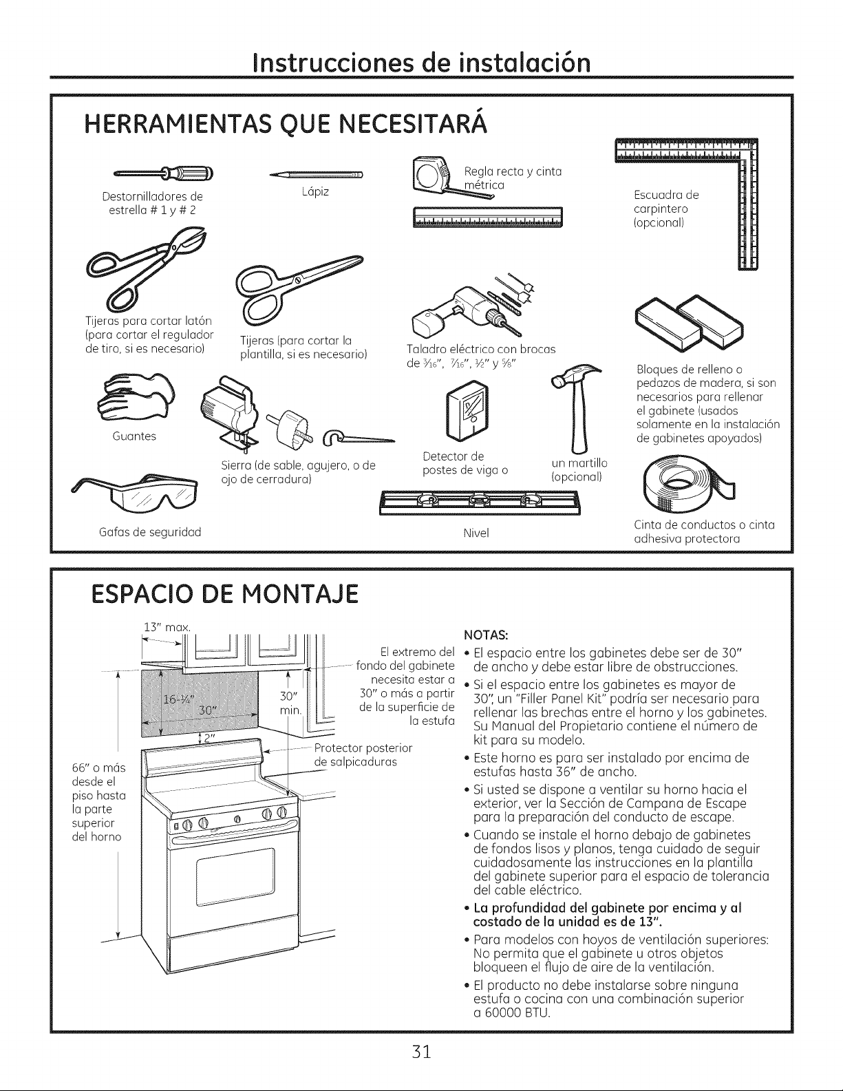
HERRAMIENTAS
Destornilladores de
estrella # i y # 2
Tijeras para cortar lat6n
(para cortar el regulador
de tiro, si es necesario)
Guantes
Tijeras(paracortar la
plantilla,sies necesario)
Sierra (de sable, agujero, o de
ojo de cerradura)
OUE
L6piz
NECESITARA
_ Regla recta y cinta
_ca
Taladro el@ctrico con brocas
de _/ld', 7/ld,,½,,y%,,
Detector de
postes de viga o (opcional)
Escuadra de
carpintero
(opcional)
Bloques de relleno o
pedazos de madera, si son
necesarios para rellenar
el gabinete (usados
solamente en la instalaci6n
de gabinetes apoyados)
un martillo
Gafas de seguridad
ESPAClO DE MONTAJE
13" max.
66" o m6s
desde el
piso hasta
la parte
superior
del homo
El extremo del
del gabinete
necesita estar a
30" o m6s a partir
de la superficie de
Protectorposterior
de salpicaduras
la estufa
Nivel
NOTAS:
. Elespacio entre los gabinetes debe set de 30"
de ancho y debe estar libre de obstrucciones.
. Siel espacio entre los gabinetes es mayor de
30",un "Filler Panel Kit" podr[a set necesario para
rellenar las brechas entre el homo y los gabinetes.
Su Manual del Propietario contiene el nOmero de
kit para su modelo.
Este homo es para set instalado por encima de
estufas hasta36" de ancho.
Siustedsedisponea ventilarsu homo haciael
exterior,verlaSecci6nde Campana de Escape
paralapreparaci6ndelconductode escape.
Cuando seinstaleelhomo debajode gabinetes
derondoslisosy planos,tengacuidadodeseguir
cuidadosamentelasinstruccionesen laplantilla
delgabinetesuperiorparaelespaciode tolerancia
delcableel6ctrico.
. La profundidad del gabinete por encima y el
costado de la unidad es de 13".
. Para modelos con hoyos de ventilaci6n superiores:
No permita que el gabinete u otros objetos
bloqueen el flujo de aire de la ventilaci6n.
El producto no debe instalarse sobre ninguna
estufa o cocina con una combinaci6n superior
a 60000 BTU.
Cinta de conductos o cinta
adhesiva protectora
31
Page 32
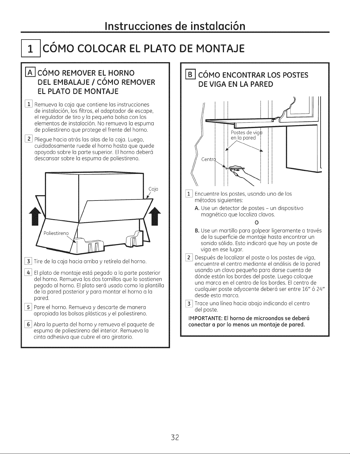
Instrucdonesde instalaci6n
C6MO COLOCAR EL PLATO DE MONTAJE
r_C6MO REMOVER EL HORNO
DEL EMBALAJE / C6MO REMOVER
EL PLATO DE MONTAGE
%
Remueva la CGjQque contiene las instrucciones
de instalaci6n, los filtros, el adaptador de escape,
el regulador de tiro y la peque_a bolsa con los
elementos de instalaci6n. No remueva la espuma
de poliestireno que protege el frente del horno.
[]
Pliegue hacia atr6s las alas de la caja. Luego,
cuidadosamente ruede el horno hasta que quede
apoyado sobre la parte superior. Elhomo deber6
descansar sobre la espuma de poliestireno.
Poliestireno
\
[_ Tire de la caja hacia arriba y ret[rela del homo.
%
Elplato de montaje est6 pegado a la parte posterior
del homo. Remueva los dos tornillos que Io sostienen
pegado al horno. El plato ser6 usado como la plantilla
de la pared posterior y para montar el homo a la
pared.
[_ Pare el horno. Remueva y descarte de manera
apropiada las bolsas plesticas y el poliestireno.
[_ Abra la puerta del homo y remueva el paquete de
espuma de poliestireno del interior. Remueva la
cinta adhesiva que cubre el aro giratorio.
rz_jBjC6MO ENCONTRAR LOS POSTES
DE VIGA EN LA PARED
Postesdevig_
enla pared i
[] Encuentre los postes, usando uno de los
m@odos siguientes:
A. Use un detector de postes - un dispositivo
magn@ico que Iocaliza clavos.
0
B. Use un martillo para golpear ligeramente a trav6s
de la superficie de montaje hasta encontrar un
sonido s61ido.Esto indicar6 que hay un poste de
riga en ese lugar.
Despu6s de Iocalizar el poste o los postes de riga,
%
encuentre el centro mediante el an61isisde la pared
usando un clavo peque_o para darse cuenta de
d6nde est6n los bordes del poste. Luego coloque
una marca en el centro de los bordes. Elcentro de
cualquier poste adyacente deber6 set entre !6" 6 24"
desde esta marca.
[_ Trace una I[nea hacia abajo indicando el centro
del poste.
IMPORTANTE:El homo de microondas se deber6
conectar a por Io menos un montaje de pared.
32
Page 33

Instruccionesde instalaci6n
C6MO DETERMINAR LA LOCALIZACION DEL PLATO DE MONTAJE DEBAJO
DE SU GABINETE
Posici6n del plato - debajo de gabinetes
de rondo piano
Las orejillas del plato
de montaje tocan el
fondo del gabinete
o
°oIo
Por to menos 30", hasta 36"
Posici6n del plato = debajo de gabinetes
de rondo apoyado en un marco
Lasorejillasdel
plato de montaje
tocan el marco
posterior
30"'hasta la estufa
Posici6n del plato - debajo de gabinetes
de fondo apoyado con frente saliente
30"hasta la estufa
Plato de montaje
con orejillas por
debajo del fondo
del gabinete a la
misma distancia
la profundidad
del saliente
Susgabinetes podrfan tener marcos de decoraci6n
que interfieran con la instalaci6n del homo. Remueva
los marcos decorativos para instalar el homo
apropiadamente y para hacer que quede nivelado.
ELHORNO DEBEQUEDAR NIVELADO.
Use un nivel para cerciorarse de que el fondo
del gabinete est6 nivelado.
Si los gabinetes tienen un saliente frontal solamente,
sin marco posterior o lateral, instale el plato de montaje
a la misma distancia de la profundidad del saliente.
Este mantendr6 el homo nivelado.
[] Mida la profundidad interna del frente del saliente.
[_ Trace una linea horizontal en la pared posterior
a una distancia debajo del fondo del gabinete igual
a la profundidad interna del frente saliente.
[_ Para este tipo de instalaci6n con saliente frontal
solamente, alinee las orejillas de montaje con la linea
horizontal, sin tocar el fondo del gabinete como
sedescribi6 en el PasoD.
33
Page 34

Instruccionesde instalaci6n
_'] C6MO ALINEAR EL PLATO DE MONTAJE SOBRE LA PARED
Agujero
.................. I..................
Agujero C
I
O0OO0000100000000
000o0o00_00000o00
?........T
Area E J
PRECAUCION:
Use guantesde protecci6n
paraevitarcortaduras en sus
dedoscon lose×tremosfilosos.
[] Trace una I[neavertical en la pared en el centro
del espacio de :SO"de ancho.
[_ Useel plato de montaje coma la plantilla para la pared
posterior. Coloque el plato de montaje en la pared,
cercior6ndose de que lasorejillas se encuentran tocando
el fondu del gabinete o la I[neamarcada en el PasoC
para losgabinetes con salientes frontales. Alinee
la muesca y I[nea delcentro en el plato de montaje
con la I[neade centro en la pared.
[_ Mientras sostiene el plato de montaje con una mano,
trace drculos en la pared en los agujeros A, B,Cy D
(vet la ilustraci6n anterior / la placa real est6 marcada
con flechas). Deben usarse cuatro agujeros para
el montaje.
Traceuna linea
vertical en la
pareda partirdel
_--centro delgabinete
superior
_Agujero B
/
Agujero D
I
NOTA:Losagujeros C y Dvan en el interior del 6rea E.
Si ni el C niel Dest6n en un paste de viga, encuentre
un paste en alg0n otro lugar en el 6rea Ey marque
un quinto drculo para alinearse con el paste.
Esimportante usar par Io menus un tornillo de madera
montado firmemente en un paste para apoyar el peso
del horno.
Apurte el pluto de montuje.
ADVERTENCIA: Riesgodedescorgo
el_ctrico. Puede provocor lesiones o Io muerte. Tango
cuidudo de no pefforar elcableado el_ctrico ubicodo
dentro de los parades o gabinetes.
[_ Perfore agujeros en losc[rculos. Sihay un paste de
riga, peffore un agujero de 3/!6" para los tornillos de
madera. Para los agujeros que no quedaron alineados
con el paste de riga, perfore un agujero de 5/8" para
los tornillos basculantes.
NOTA: TODAViA NO MONTE EL PLATO.
34
Page 35
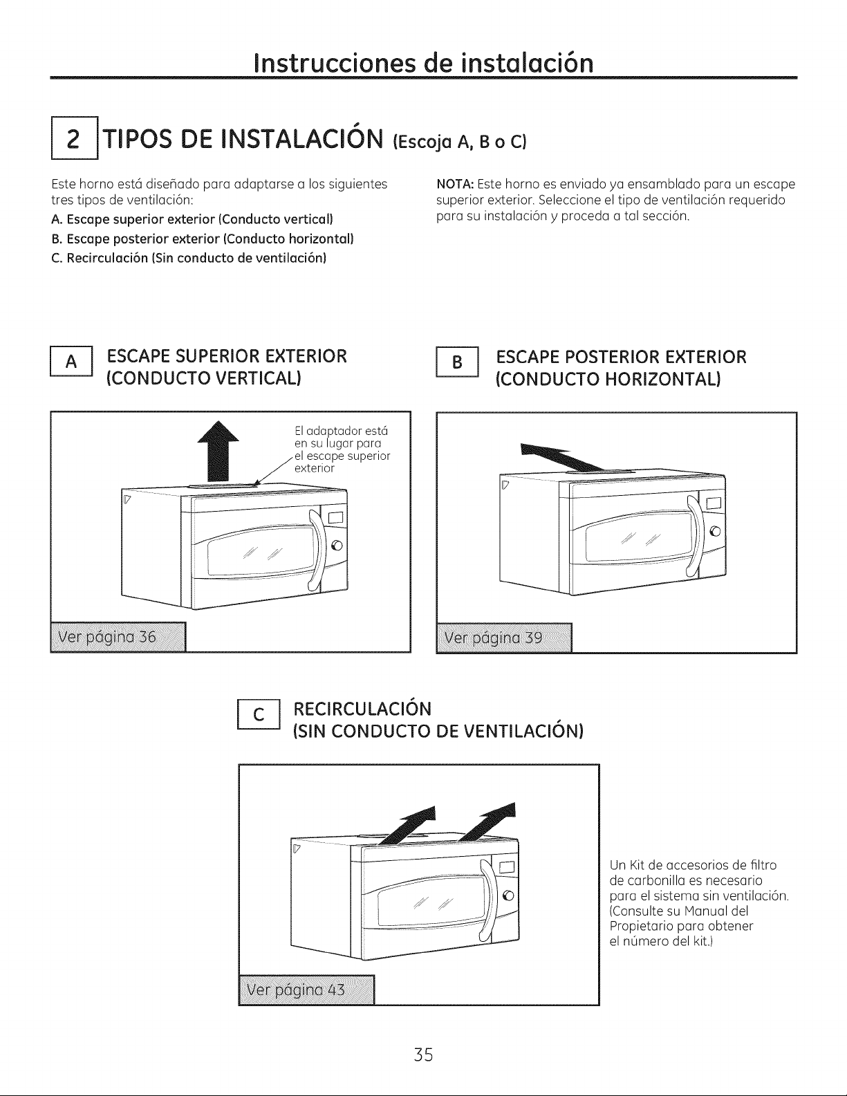
Instruccionesde instalaci6n
I--2-JTIPOS DE INSTALACI6N
Este homo est6 dise_ado para adaptarse a los siguientes
tres tipos deventilaci6n:
A. Escape superior exterior (Conducto vertical)
B. Escape posterior exterior (Conducto horizontal)
C. RecJrculacJ6n (Sin conducto de ventilacJ6n)
j_ SCAPE SUPERIOR EXTERIOR
(CONDUCTO VERTICAL)
Eladaptador est6
ensu lugar para
escapesuperior
exterior
(Escoja A, B o C)
NOTA:Este homo es enviado ya ensamblado para un escape
superior exterior. Seleccione el tipo de ventilaci6n requerido
para su instalaci6n y proceda a tal secci6n.
J_ SCAPE POSTERIOR EXTERIOR
(CONDUCTO HORIZONTAL)
j_----j REClRCULACI6N
(SIN CONDUCTO DE VENTILACI6N)
35
Un Kit de accesorios de filtro
de carbonilla es necesario
para el sistema sin ventilaci6n.
(Consulte su Manual del
Propietario para obtener
el nOmero del kit.)
Page 36

Instrucdonesde instalaci6n
ESCAPESUPERIOR EXTERIOR(Conducto vertical)
PERSPECTIVA GENERAL
DE LA INSTALACION
AI. Como adherir el plato de montaje
a la pared
A2. Prepare el gabinete superior
A3. Instale el adaptador
A4. Monte el homo
A5. Ajuste el adaptador
de escape
A6. Conecte el conducto
COMO ADHERIR LA PLACA
DE MONTAJE A LA PARED
A _Bi::
Pegue el plato a la pared usando los tornillos
basculantes. Por Io menos un tornillo de madera debe
ser usado para pegar el plato al poste de la pared. Las
ubicaciones recomendadas sobre la placa de montaje
se indican enA, B,Cy D.
[_ Remueva las mariposas del basculante de los
tornillos.
[_ Inserte los tornillos en el plato de montaje atrav6s
de los agujeros dise_ados para ser insertados en
la pared de mamposterfa seca y pegue otra vez
las mariposas de¾" en cada tornillo.
Para usar los tornillos basculantes:
Espaciadorespara los
basculantesmayores
÷_.._j_..-J que elanchode lapared
Plato de
monta
[_ Coloque el plato de montaje contra la pared e inserte
las alas de mariposa en los agujeros de la pared para
montar el plato.
NOTA:Antes de apretar los tornillos basculantes
y lostornillos de madera, cerci6rese de que las orejillas
en el plato de montaje toquen el fondo del gabinete
cuando son empujadas contra lapared y de que el plato
est6 centrado apropiadamente debajo del gabinete.
A "
PRECAUCION:Tenga cuidadode evitar
pellizcarsusdedos entrelaparteposteriordelplato
de montajey lapared.
[_ Apriete todos los tornillos. Tire del plato
en direcci6n opuesta a la pared para ayudar
a apretar los tornillos.
i Alas demariposa
"_-Pared
Extremodeltornillo
36
Page 37

Instruccionesde instalaci6n
USE LA PLANTILLA DEL GABINETE
SUPERIOR PARA LA PREPARACION
DEL GABINETE SUPERIOR
Deber6 perforar agujeros para los tornillos de apoyo
superiores, un agujero suficientemente grande para que
el cable el#ctrico quepa, y un recorte Io suficientemente
grande coma para que el adaptador de escape pueda
set introducido.
, Lea los instrucciones sabre la PLANTILLA
DELGABINETESUPERIOR.
, P_guelo debajo del gabinete superior.
, Taladre los agujeros, siguiendo los instrucciones
en la PLANTILLADELGABINETESUPERIOR.
A
PRECAUCION:Use gclfclsde seguridcld
cuando perfore los agujeros en el fondo del gabinete.
COMO MONTAR EL HORNO
A _,,-.,rr^, ,,_,,_,,,
J4k I_l_P-.l.,#'_Ul,_l_,;m: A finde evitclr el
riesgo de lesi6n personal {lesi6n en la espalda u
otras lesiones debido a peso excesivo del homo
de microondasl o da_os sabre el producto,
deber6 contar con la ayuda de dos personas
par(] instalar este homo de microondas.
IMPORTANTE:No tome ni use la manija durante la
instalaci6n.
kADVERTENCIA: Riesgo de
Descarga El_ctrica. Puede ocasionar lesiones o la
muerte: si instala la unidad con encimeros de metal,
cubra el agujero del extremo del cable de suministro
de corriente con aislante para el cable del suministro
de corriente.
IHPORTANTE: Si no se usan bloqueadores de filtro,
se podr6n producir daflos en la caja debido al ajuste
excesivo de los tornillos.
ENSAMBLAJE E INSTALACION
DEL ADAPTADOR
tiroRegulad°rde
Adaptador
fi_.i__ de escape
Platodel
calefactor
__ Porte
....
[_ Coloque el horno en su posici6n vertical, con la parte
superior hacia arriba.
[_ Inserte los orejillas en coda lado del regulador de tiro
en los agujeros en el interior posterior del adaptador.
[_ Pegue el adaptador de escape al plato calefactor con
los dos tornillos de bronce que le proporcionamos.
Cerci6rese de que el regulador de tiro gira
f6cilmente antes de montar el homo.
Deber6 hacer ajustes para asegurarse de que existe
alineaci6n apropiada con el sistema de conductos
de su casa despu#s de la instalaci6n del horno.
NOTA: Cuando se encuentre
montando el homo, enrosque
el cable el@ctrico a trav@s
del agujeroen elfondo
del gabinetesuperior.
Mant_ngalotenso a trav_sde
losPasosdel 1-3. ' _]No pelhzque
el cable nitiredel homo_,por L_Jhaciaadelante,y enganche
el cable. "_ los ranuras enel extremo
[]Gire el frente del homo contra
el fondo del gabinete.
[_ Inserte un tornillo de autoalineaci6n a trav#s del
agujero central superior del gabinete. Asegure el homo
temporalmente girando el tornillo par Io menos dos
vueltas completas despu#s de que los roscas hayan
agarrado. (Luego quedar6n totalmente apretadas).
Levanteel
inferiorposterioren dos
orejillasinferioresdelplato
de montaje.
homo,
incl[nelo
37
Page 38

Instruccionesde instalaci6n
COHO MONTAR EL HORNO
(continuaci6n}
[_ Pegue el homo o Io porte superior del gubinete.
[_ Inserte 3 tornillos (VJ'-28 x 2 sA")
outoalineables a troves de los agujeros
exteriores superiores del homo. Gire
dos vueltas completos en coda tornillo.
Apriete eltornillo del centro
completumente.
Frente del gubinete
Estunte del fondo del gubinete
Bloque de relleno
FATJ C6MO AJUSTAR EL ADAPTADOR
DE ESCAPE
Abra el gabinete superior y ajuste el adaptador
de escape para conectarlo al conducto de la casa.
Regulador de tiro
!
Parte
posterior
del homo
/
C6MO CONECTAR EL CONDUCTO
Conducto de la casa
quivalentea t
profundidadI
elretroceso|
Tornillo autoalineable
Porte superior del homo
[] Apriete los dos tornillos exteriores hacia la parte
de arriba del horno. (Mientras aprieta lostornillos,
mantenga el homo ensu lugar contra la pared
y el gabinete superior.)
[_ tnstale los filtros de grasa. Ver el Manual del Propietario que
viene con elhomo.
Estadistancia NO
puede superar las
2" para asegurar
una instalaci6n
adecuada.
[] Extienda el conducto de la casa hacia abajo para
conectarlo con el adaptador de escape.
[_ Selle lasjuntas del conducto de escape usando
anta adhesiva de conductos.
38
Page 39
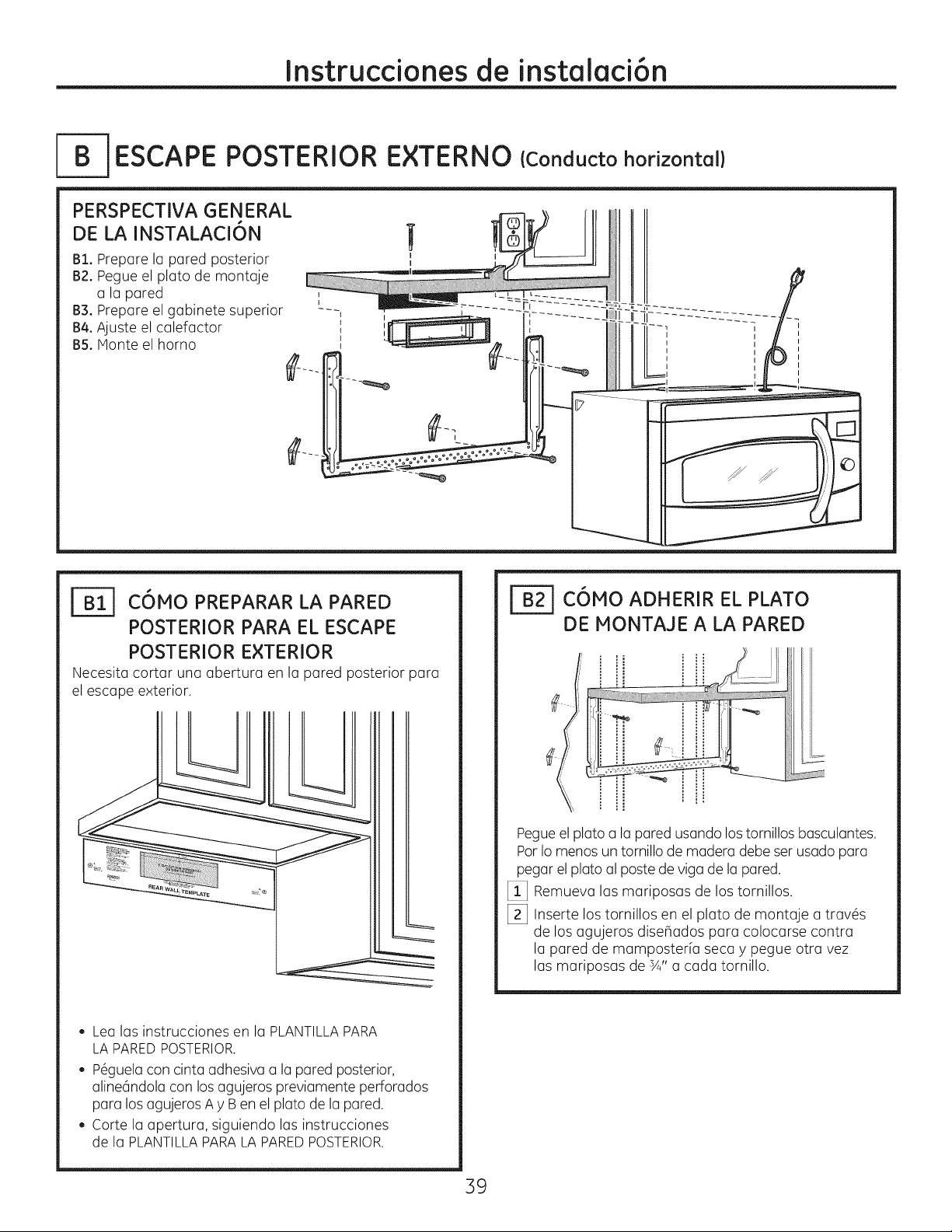
Instruccionesde instalaci6n
ESCAPE POSTERIOR
E×TERNO
PERSPECTIVA GENERAL
DE LA INSTALACI6N
Blo Prepare la pared posterior
B2. Pegue el plato de montaje
a la pared ,
B3oPrepare el gabinete superior ---,
B4oAjuste el calefactor _
B5. Monte el horno
I
C6HO PREPARAR LA PARED
POSTERIOR PARA EL ESCAPE
POSTERIOR EXTERIOR
Necesita cortar una abertura en la pared posterior para
el escape exterior.
(Cond ucto horizonta I)
I
I
I
I
C6HO ADHERIR EL PLATO
DE !ONTAJE A LA PARED
. ! Hjii
. Lea las instrucciones en la PLANTILLAPARA
LAPAREDPOSTERIOR.
, P6guelacon cinta adhesiva a la pared posterior,
aline6ndola con los agujeros previamente perforados
para losagujeros A y Ben el plato de la pared.
Corte la apertura, siguiendo las instrucciones
de la PLANTILLAPARALA PAREDPOSTERIOR.
Pegueel plato a lapared usando lostornillos basculantes.
Pot Iomenos un tornillo de madera debe ser usado para
pegar el plato al poste de riga de la pared.
[] Remueva las mariposas de los tornillos.
[_ Inserte los tornillos en el plato de montaje a tray,s
de los agujeros dise_ados para colocarse contra
la pared de mamposteHa secay pegue otra vez
las mariposas de sA"a cada tornillo.
39
Page 40
Instruccionesde instalaci6n
Para usar los tornillos basculantes:
[_ Coloque el plato de montaje contra la pared
e inserte las alas de mariposa en los agujeros
de la pared para montar el plato.
NOTA:Antes de apretar lostornillos basculantes
y el tornillo de madera, cerci6rese de que las orejillas
en el plato de montaje toquen el fondo del gabinete
cuando se empujen contra la pared y de que el plato
est6 centrado apropiadamente debajo del gabinete.
A "
PRECAUCION:Tenga cuidadode evitar
pellizcar sus dedos entre la parte posterior del plato
de montaje y la pared.
[_ Apriete todos lostornillos.Tiredel plato en direcci6n
opuesta a la pared para ayudar a apretar los tornillos.
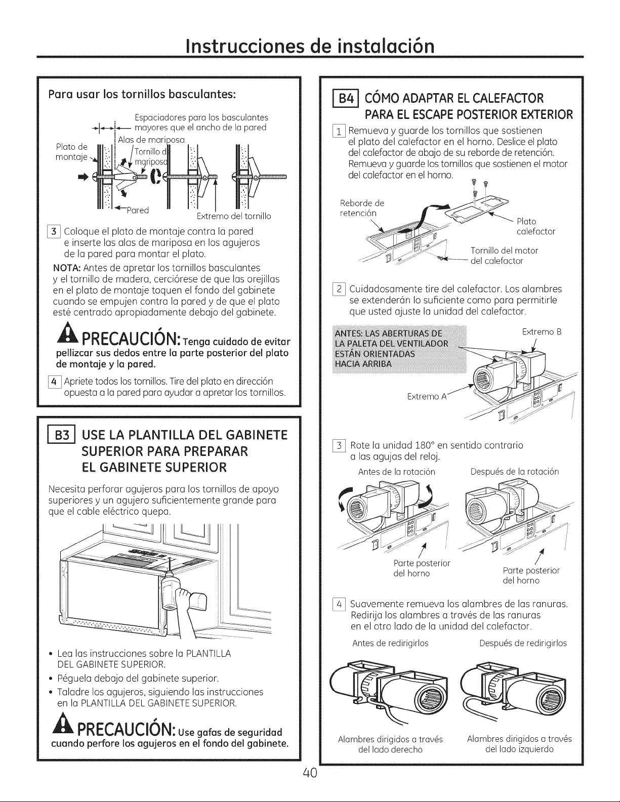
C6NO ADAPTAR ELCALEFACTOR
PARA ELESCAPE POSTERIOR EXTERIOR
[_ Remueva y guarde los tornillos que sostienen
el plato del calefactor en el homo. Desliceel plato
del calefactor de abajo desu reborde de retenci6n.
Remuevay guarde lostornillos que sostienen el motor
del calefactor en el horno.
Rebordede __ _ ji!-_<_
retenci6n __
\. __j_ _" Plato
__ calefactor
"__ Tornillo del motor
...._ J "_.--' _ delcalefactor
I_ Cuidadosamente tire del calefactor. Los alambres
se extenderdn Io suficiente como para permitirle
que usted ajuste la unidad del calefactor.
Extremo B
Extremo
USE LA PLANTILLA DEL GABINETE
SUPERIOR PARA PREPARAR
EL GABINETE SUPERIOR
Necesita perforar agujeros para lostornillos de apoyo
superiores y un agujero suficientemente grande para
que el cable el6ctrico quepa.
, Lea las instrucciones sobre la PLANTILLA
DELGABINETESUPERIOR.
, P_guela debajo del gabinete superior.
, Taladre los agujeros, siguiendo las instrucciones
en la PLANTILLADELGABINETESUPERIOR.
A "
PRECAUCION:Use galasde seguridad
cuando perforelosagujerosen elrondo delgabinete.
[_ Rote la unidad 180° en sentido contrario
a las agujas del reloj.
Antes de la rotaci6n
! !
Parteposterior
del homo Parteposterior
[_ Suavemente remueva los alambres de las
RedirUa los alambres a trav@s de las ranuras
en el otro lado de la unidad del calefactor.
Antes de redirigirlos Despu6s de redirigirlos
Alambres dirigidos a trav6s
del lado derecho
Despu6s de la rotaci6n
del homo
Alambres dirigidos a trav6s
del lado izquierdo
ranuras.
40
Page 41
Instrucdonesde instalaci6n
[_] Ruede la unidad del calefactor 900 de forma tal
que los aberturas de la paleta del ventilador est6n
orientadas hacia la parte posterior del homo.
Antes de la rotaci6n
_jJ"
_Parte
posterior
clelhomo
Localice los dos platos removibles en el panel
%
posterior del homo, cerca de la parte superior
del horno.
Usando tijeras, cuidadosamente corte el 6tea
de telaraBa de los dos agujeros lado a lado
(que aseguran los platos removibles al homo).
Corte los cuatro telaraBas en ambos platos
removibles posteriores; esto permitir6 que el
flujo de aire del ventilador escape hacia la parte
posterior del homo.
A °
PRECAUCION:Cerd6rese de
recortarlosextremosfilososde losaberturas
despu6sde removerlosplatos.
Parteposterior det homo
Despu6s
de la rotaci6
Parte_
posterior
del homo
Corte con tijeras los
cuatro telarar_as de
cada panel removible
y remueva los discos
removibles de metal
para permitir el flujo
de aire )osterior.
[] Coloque el plato calefactor en la misma
posici6n como estaba antes con los tornillos.
Tornillosdel plato calefactor
Platocalefactor
Parte
posterior
__., del homo
_] Inserte los orejillas en coda lado del regulador
de tiro en los agujeros en el lado interior
posterior del adaptador.
I
_J i
_- Adaptador
<_ deescape
Pegue el adaptador de escape a la parte posterior
del homo desliz6ndolo en las guias en la parte
superior central de la parte posterior del horno.
Adaptador
de escape
Deslice el
adaptador de
escape en las
guias de la
parte t
clel homo
Reguladordetiro
(bisagrahacia
arriba)
Parte
posterior
clelhomo
[_ Coloque la unidad del calefactor de
en la abertura.
Extremo B
nuevo
A
ADVERTENCIA:E×isteriesgo de
descargas el6ctricas que pueden ocasionar
lesiones o la muerte. No empuje ni extienda el
cableado de la unidad de ventilaci6n. Aseg6rese
de que los cables no posean cortes.
NOTA:Las aberturas de la salida de la unidad de
ventilad6n deben coincidir con los aberturas de
salida de la porte trasera del homo de microondas.
Guias
Empuje firmemente hasta que est6 en los orejillas
de cierre inferiores, Tango cuidado de asegurarse
de que la bisagra del regulador de tiro est6
instalada de forma que est6 en la porte superior
y que el regulador de tiro gire libremente.
I_ Asegure el adaptador de escape al horno
con los dos tornillos met61icos de bronce
que proporclonamos.
41
Page 42

Instruccionesde instalaci6n
COHO IONTAR EL HORNO
Ar, r,r-r^,
,-,rRc u .lul, : A deevitoreJ
riesgo de lesi6n personal (lesi6n en la espalda u
otras lesiones debido a peso excesivo del homo
de microondas) o daffos sobre el producto,
deber6 contar con la ayuda de dos personas
para instalar este homo de microondas,
IMPORTANTE:No tome ni use la manUa durante la
instalaci6n.
AADVERTENCIA: Riesgo de
Descarga EI6ctrica. Puede ocasionar lesiones o la
muerte: si instala la unidad con encimeros de metal,
cubra el agujero del extremo del cable de suministro
de corriente con aislante para el cable del suministro
de corriente.
IHPORTANTE: Si no se usan bloqueadores de filtro,
se podr6n producir dahos en la caja debido al ajuste
excesivo de lostornillos.
Frente del gabinete
Estante del fondo del gabinete
Bloque de relleno
"-_quivalente a
Ilaprofundidac
I deJretsoceso
,_del gabinete
Tornillo autoalineable
Porte superior del horno
[_ Pegue el horno a la parte superior del gabinete.
I_ Inserte 3 tornillos (Y_"-28x 2 %")
autoalineables a trav6s de los agujeros
exteriores del horno. Gire dos vueltas
completas en cada tornillo.
Esta distancia NO
puede superar las
2" para asegurar
una instalaci6n
adecuada.
NOTA: Cuando se encuentre
montando el homo, enrosque
el cable el#ctrico a trav#s
del agujero en el fondo
del gabinete superior.
Mant6ngalo tenso a trav6s de
los Pasos del 1-3. No pellizquel_ _ Levante el homo, inclinelo
el cable ni tire del homo par L:_ hacia adelante, y enganche
el cable, las ranuras en el extremo
inferior posterior en dos
orejillas inferiores del plato
de montaje.
I_ Gire el frente del homo contra
el fondo del gabinete.
[_Inserte un tornillo de autoalineaci6n a trav6s del
agujero central superior del gabinete. Asegure el homo
temporalmente girando eltornillo par Iomenos dos
vueltas completas despu6s de que las roscas hayan
agarrado. (Luego quedaran totalmente apretadas).
Apriete el tornillo del
centro completamente.
[] Apriete los dos tornillos exteriores hacia la parte
de arriba del homo. (ivlientras aprieta los tornillos,
mantenga el homo en su lugar contra la pared
y el gabinete superior.)
ii )
:. -_ /
.....................................................,,,
I_ Instale los filtros de grasa. Ver el Manual
del Propietario que viene con el horno.
42
Page 43
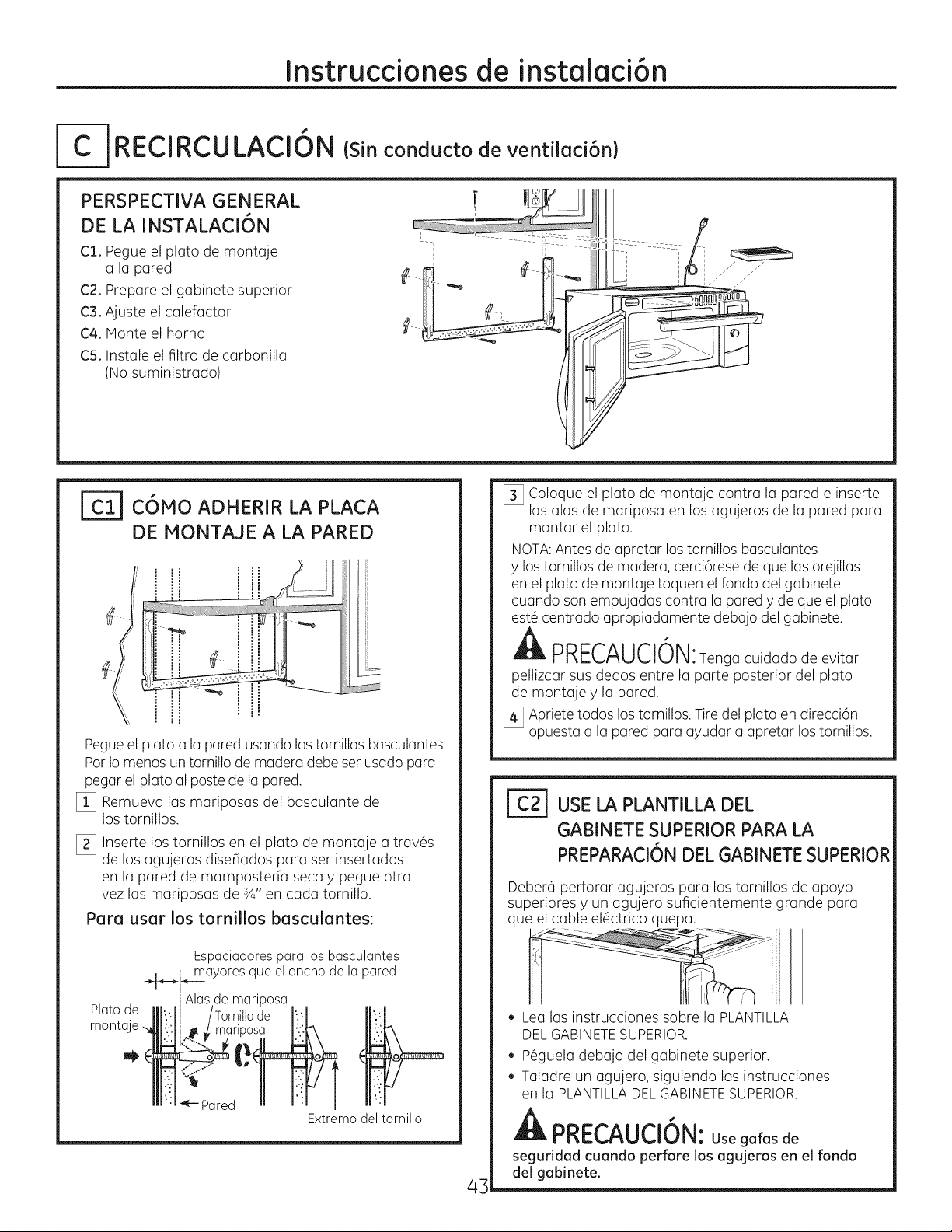
Instrucdonesde instalaci6n
RECIRCULACION Csinconducto de ventilaci6n)
PERSPECTIVA GENERAL
DE LA INSTALACION
Cl. Pegue el pluto de montuje
a la pored
(:;2.Prepare el gabinete superior
C3. Ajuste el calefactor
C4. Monte el homo
C5. Instale el filtro de carbonilla
(Nosuministrado)
I
I
I//
COMO ADHERIR LA PLACA
DE MONTAJE A LA PARED
Pegueel plato a la pored usondo lostornillos bosculantes.
ParIomenos un tornillo de modero debe serusado para
pegar el plato ol paste de la pored.
[] Remueva las mariposas del basculante de
lostornillos.
[_ Inserte los tornillos en el plato de montaje otrav6s
de los agujeros disehados para ser insertodos
en Io pored de momposterfa seco y pegue otra
vez las mariposas de sA"en cada tornillo.
Para usar los tornillos basculantes:
[_ Coloque el plato de montaje contra la pared e inserte
las alas de mariposa en los agujeros de la pared para
montar el plato.
NOTA:Antes de apretar los tornillos basculantes
y lostornillos de madera, cerci6rese de que las orejillas
en el plato de montaje toquen elfondo del gabinete
cuando son empujadas contra la pared y de que el plato
est_ centrado apropiadamente debajo del gabinete.
A "
PRECAUCION:Tenga cuidado de evitar
pellizcar sus dedos entre la parte posterior del plato
de montaje y la pared.
[_ Apriete todos los tornillos. Tire del plato en direcci6n
opuesta a la pared para ayudar a apretar lostornillos.
[=_ USELA PLANTILLA DEL
GABINETE SUPERIORPARA LA
PREPARACI6NDEL GABINETESUPERIOR
Deber6 perforar agujeros para los tornillos de apoyo
superiores y un agujero suficientemente grande para
que el cable el6ctrico quepa.
Plato de
manta
Espaciadorespara los basculantes
: mayoresque elancho de la pared
JAlasde mariposa
::;L
_---Pared n _._
Extremodeltornillo
. Lea las instrucciones sabre la PLANTILLA
DELGABINETESUPERIOR.
. P_guela debajo del gabinete superior.
. Taladre un agujero, siguiendo las instrucciones
en la PLANTILLADELGABINETESUPERIOR.
PRECAUCION:Use gafas de
seguridad cuando perfore los agujeros en el fondo
del gabinete.
43
Page 44

Instruccionesde instalaci6n
COMO ADAPTAR EL CALEFACTOR
PARA LA RECIRCULACION
NOTA: Eladaptador de escape con calefactor
no es necesario para los modelos de recirculaci6n.
Quiz6s desee guardarlos para posibles usos futuros.
%
Remueva y guarde los tornillos que sostienen
el plato del calefactor en el homo.
f_-J-Tornillos del platodel
11_i_calefactor
Parteposterior
.... del homo
[_ Deslice el plato calefactor por debajo de su reborde
de retenci6n. Remueva y guarde lostornillos que
sostienen el motor del calefactor al horno.
Rebordede _
retenci6_, _'_'_____
[_ Cuidadosamente tire del calefactor. Los alambres
se extender6n Io suficiente para permitirle que
usted ajuste la unidad del calefactor.
[_ Ruede la unidad del calefactor 900de forma tal
que las aberturas de la paleta del ventilador est6n
orientadas hacia el frente del microondas.
.... -J .... .ssl
_ "_/ _actor
_'__ .... "--_,_------Tornillodel motor
__ _ _--_-_" "_- delcalefactor
Ruede
NOTA:Cerci6rese de que los alambres permanecen
encaminados en las ranuras del marco del motor.
44
Page 45

Instruccionesde instalaci6n
COMO ADAPTAR EL CALEFACTOR
PARA LA RECIRCULACION
(continuad6n)
I_ Coloque la unidad del calefactor de nuevo en la
abertura.
ADVERTENCIA:Existeriesgode
descargas el6ctricas que pueden ocasionar lesiones o
la muerte. No empuje ni extienda el cableado de la
unidad de ventilaci6n. AsegOrese de que los cables no
posean cortes.
[_ Asegure la unidad de ventilaci6n al homo con los 2
tornillos retirados en el Paso2. Inserte el tornillo en el
agujero del tornillo inferior derecho en la parte trasera
del homo.
[_ Reemplace el plato calefactor con los tornillos
removidos en el Paso !.
'_ _ plato calefactor
o
.... ..- Tornillo del motor
./--- Tornillos del
Parte posterior
del homo
del calefactor
F_ C6MO MONTAR EL HORNO
• I_PNI::::CAUClUN: Afin deevitarel
riesgo de lesi6n personal (lesi6n en la espalda u
otras lesiones debido a peso e×cesivo del homo
de microondas) o da_os sobre el producto,
deber6 contar con la ayuda de dos personas
para instalar este homo de microondas.
IMPORTANTE: No tome ni use la manije durante la
instalaci6n.
AADVERTENCIA: Riesgo de
Descarga El_ctrica. Puede ocasionar lesiones o la
muerte: si instala la unidad con encimeros de metal,
cubra el agujero del extremo del cable de suministro
de corriente con aislante para el cable del suministro
de corriente.
IMPORTANTE: Si no se usan bloqueadores de filtro,
se podr6n producir dahos en la caja debido al ajuste
excesivo de los tornillos.
NOTA: Cuando se encuentre
montando el homo, enrosque
el cable el@ctricoa trav@s
del agujero en el fondo
del gabinete superior.
Mant#ngalo tenso a tray,s de
los Pasos del 1-3. No pellizque I1_
el cable ni tire del homo por L_ hacia adelante, y enganche
el cable. _. las ranuras en el
Levanteelhomo,
! inferior posterior en dos
orejillas inferiores del plato
de montaje.
inclinelo
extremo
I_ Gire el frente del homo contra
el fondo del gabinete.
[_ Inserte un tornillo de autoalineaci6n a trav@s del
agujero central superior del gabinete. Asegure el homo
temporalmente girando el tornillo por Io menos dos
vueltas completas despu@sde que las roscas hayan
agarrado. (Luego quedar6n totalmente apretadas).
45
Page 46

Instruccionesde instalaci6n
F_C6MO MONTAR EL HORNO
(continuaci6n)
[_ Inse.rteun tornillo de autoalineaci6natrav@sdel
agujerocentral superiordel gabinete.Asegureelhomo
temporalmentegirando eltornillo por Iomenosdos
vueltascompletasdespu@sde que lasroscashayan
agarrado.(Luegoquedarantotalmente apretadas).
Frente del gabinete
Estante del fondo del gabinete
Bloque de relleno
J_d_aquivalenteat
profundidacJ
elretroceso|
etgabinete
Tornillo autoalineable
Parte superior del homo
[_ Inserte 3 tornillos (VJ'-28x 2 sA")
autoalineables a trav6s de los agujeros
exteriores superiores del gabinete. Gire
dos vueltas completas en cada tornillo.
EstadistanciaNO
puedesuperarlas2"
paraaseguraruna
instalaci6nadecuada.
I(::51C6MO INSTALAR EL FILTRO
DE CARBONILLA
[_ Remueva los 2 tornillos en la parte superior
del homo, justo encima de la rejilla usando
un destornillador de estrella.
[_ Abra la puerta.
[_ Remueva la rejilla.
Rejilla __Tornillos
i
[_lnserte el filtro en homo como se muestra hasta
que se ajuste correctamente en su lugar. Descansar6
en un 6ngulo detr6s de las orejillas inferiores
frontales. Cuando est6 instalado correctamente,
la malla del filtro deber[a estar visible desde el frente.
el tornillo del
centro completamente.
[] Apriete los dos tornillos exteriores hacia la parte
de arriba del homo. (ivlientras aprieta los tornillos,
mantenga elhomo en su lugar contra la pared
y el gabinete superior.)
ZIZ]II_IZ 1111
,/
illas inferiores
Filtro de carb6n
Filtro de carb6n instalado
I_ Remplace la rejilla y los dos tornillos superiores.
[_Cierre la puerta y vuelva a colocar el tornillo
del lado izquierdo.
[_ nstale los filtros de grasa. Ver el Manual
del Propietario que viene con el horno.
46
Page 47
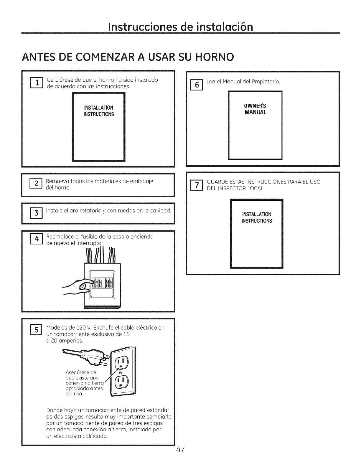
Instruccionesde instalaci6n
ANTES DE COMENZAR A USAR SU HORNO
Cerci6rese de que el horno ha sido instalado
de acuerdo con las instrucciones.
r_ Lea el Manual del Propietario.
INSTALLATION
iNSTRUCTiONS
r_ emueva todos los materiales de embalaje
del horno.
!
Instale el aro rotatorio y con ruedas en la cavidad. 1
Reemplace el fusible de la casa o encienda
de nuevo el interruptor.
OWNER'S
MANUAL
r_ UARDEESTASINSTRUCCIONESPARAEL USO
DELINSPECTORLOCAL.
|
iNSTALLATiON
INSTRUCTIONS
Modelos de 120 V:Enchufe el cable el6ctrico en
un tomacorriente exclusivo de 15
a 20 amperios.
Aseg0resede /}_'_
__lqueexiste
conexi6na tierra--
apropiada antes k._
del uso.
Donde haya un tomacorriente de pared est6ndar
de dos espigas, resulta muy importante cambiarlo
por un tomacorriente de pared de tres espigas
con adecuada conexi6n a tierra, instalado pot
un electricista calificado.
una /
47
Page 48

49-40724
HFL06244904
(06-14 GE)
Printed in Kore(]
Impreso en Core(]
 Loading...