

Page 1
XLW^ Gas Range
Sr/ÍAfbAíZP Cí-g/í/V ^ QOAfr/Aueoj CUAtJ
ÍM«íí-*tJes COyo 't //épo.
A
8ISS
Safety instructions.............................2-5
Anti-Tip Device...............................3,30,40
Aluminum Foil...........................5, 16,19, 23
Features
Surface Cooking...
....................................................
Oven
...................................................
Baking................................................15,16
Broiling, Broiling Guide...................19, 20
Clock and Timer
Control Settings
Light; Bulb Replacement........................14, 24
Preheating
Roasting, Roasting Guide
Shelves
Control Settings
Electric Ignition.
.9tanHinn Pilot Mnrifils
...............................................
................................
..................
.........................................
12-20
11,12
12,15, 17,19
15,18
......................
13-15, 23
.8-10
........
6,7
17. 18
8
.8
«
mentisi SyP€rS€.D%S
Problem Solver................
More questions ?...call
G£ Answer Center® 800.626.2000
Preparation
Flame Size
Flooring Under the Range
Installation Instructions.......................29-45
Leveling
Thermostat Adjustment.............................14
M'
Consumer Services
Appliance Registration................................2
Model and Serial Number Location............2
Warranty......................................
sòpetóEPSS 8zi^
......................................................
......................
..............................
........................
29-45
10, 34, 35,46
.....................
Back Cover
.46
31
40
47
Care and Cleaning
Air Adjustment Shutter...............................28
Broiler Drawer............................................27
Rrnilor Pan anrl Par'll 1Q OQ
■^1 WItWI I Vli I V4I IV« I IW4WIX I KAf
Burner Assembly
Door Removal
Lift-up Cooktop
Oven Bottom
Oven Vents
Storage Drawer
GE Appliances
...........
..................................
........................................
..........................................
..............................................
..................................
..........................................
4, 5,13, 28
!MSm¿I
21-28
21,22
25
28
23
27
Standard-Clean Models:
JGBS02EN
JGBS02PN JGBS12GER
JGBS04ER JGBS15GER
JGBS04PR JGBS16GEP
JGBS04GER
JGBS04GPR JGBS19GEP
JGBS06ER
Continuous-Clean Models:
JGBC15GER JGBC18GEP
JGBC17GER
‘^l-93Sg
JGBS06PR
JGBS17GER
JGSS05GER
Page 2

HELP US HELP YOU
Mead this book carefully.
It is intended to help you operate
and maintain your new range
properly.
Keep it handy for answers to your
questions.
If you don’t understand something
Or need more help, write (include
your phone number):
Consumer Affairs
GE Appliances
Appliance Park
Louisville, KY 40225
Write down the mode! and serial numbers.
Depending on your range, you’ll
find the model and serial numbers
on a label on the front of the range,
U^liXXlU. LilW AJL\./XV
drawer or broiler drawer.
TTiAc#» mi-mVt/arc arA islcrt nn ttiA.
JL JLAV/OW . AAVftXAXV/WJU CV
Consumer Product Ownership
Registration Card that came
with your range. Before sending
in this card, please write these
Model Number
Serial Number
Use these numbers in any
correspondence or service calls
If you received
a damaged range...
Immediately contact the dealer (or
K^^ílrl<ar^ tVlilt onlH \;r\n tViA
L/iXXXVXWJ. J VXAUI, OV/IVI* J WAXW
Save time and money. Before you request service...
Check the Problem Solver in the
Ui UU&» uuuiv. XL ixdid kjl
minor operating problems that you
can correct yourself.
IF YOU NEED SERVICE...
"ÜTD OnP
To obtain service, see the Consumer
Services page in the back of this
book.
To obtain replacement parts, contact
GE/Hotpoint Service Centers.
We’re proud of our service and
want you to be pleased. If for some
reason you are not happy with the
service you receive, here are three
steps to follow for further help.
WARNING; If the information in this manual is not followed exactly, a fire or explosion may result
miislnp nmiM^rtv damsi^e. nersonal iitiurv or death.
o X'-’
---------------------------------------
-Do not store or use gasoline or other
flammaMe vapors and liquids in the vicinity
of thk or any other appliance.
TO bo IF YOU S№LL GAS
»Do not try to light any appliance.
® Do not touch any electrical switch; do not
use any phone In yoiir hulldtng.
x^xjvoXÿ uumaL^L uit? wiix/
serviced your appliance. Explain
why you are not pleased. In most
cases, this will solve the problem.
NEXT, if you are still not pleased,
write all the details—including
your phone number—to:
Manager, Consumer Relations
GE Appliances
Appliance Park
Louisville, KY 40225
--------------------
.
® Immediately call your gas supplier from a
neighbor’s phone. Follow the gas supplier’s
mstmctlons.
® If you cannot reach your gas supplier, call
the fire departoent
• Installation and service must be performed
by a qualified hisialler, skvice agency or
the gas supplier.
TTTTVTAT TV i'F t/rMif r\rr%K1^Tn -Jo ctJll
JL XX ^V/UX ^XV/X/XWXXX XO kJXXXX
not resolved, write:
Major Appliance Consumer
20 North Wacker Drive
/-lui___
Action Panel
TT
uu Duouo
Page 3
IMPORTANT SAFETY INSTRUCTIONS
Read ail instructions before using this appliance.
- IMPORTANT SAFETY NOTICE
The California Safe DrinMng Water and Toxic
Enforcement Act requires the Governor of
California to publish a list of substances known
to the state to cause cancer, birth defects or other
reproductive harm, and requires businesses to warn
customers of potential exposure to such substances.
Gas appliances can cause minor exposure to
four of these substances, namely benzene, carbon
monoxide, formaldehyde and soot, caused primarily
by the inconiplete combustion of natural gas or
LP fuels. Properly adjusted burners, indicated by
a bluish rather than a yellow flame, will inininiize
incomplete combustion. Exposure to these
substances can be nüiiiiïiized by venting with an
open window or using a ventilation fan or hood.
When You Get Yoer Range
« Have thé instalier show you the location of the
range gas cut-off valve and how to shut it off
ifuecessary. ■ ^ : - . : ; , .
®Hfeve your range installed and properly
groiinded by a qualified installer, in accordance
with the Installation Instructions. Any adjustment
and service should be performed only by qualified
gas range installers or service technicians.
® Plug your range Into a 120-volt grounded
outlet only. Dp not remove the round grounding
prong from ihe plug; n in doubt about the grounding
of the home electrical system, it is your personal
responsibility and obligation to have an ungrounded
outlet replaced with a properly grounded, threeprong outlet in accordance with the National
Electrical Gode. In Canada, the appliance must
be electrically grounded in accordance with the
Canadian Electrical Code. Do not use an
extension cord with this appliance.
® Be sure ai pacldug materials are removed from
the raîîge before operating it to prevent fire or
smoke ckmage should the packing material ignite.
® Locate range out of kitchen traffic path
and out of draftv locations to orevent uilot
outage (on models with standing pilots) and
poor air circulation.
Be sure your range is correctly adjusted by a
qualified service technician or installer for the
type of gas (natural or LP) that is to be used*
Your range can be converted for usé with either
tvne of eas. See Installation Instructions.
After prolonged use of a range, hi^ fioor
temperatures may result and many floor
coverings will not withstand this Idnd of use.
Never install the range over vinyl tile or linoleum
that cannot withstand such type of use. Never
install it directly over interior kitchen carpeting.
Using Your Range
• Don’t leave children alone or uimttended where
a range is hot or in operation. They cpuid be
seriously burned.
• Don’t allow anyone to climbs stand or hang on
the door, storage or broiler drawer (on some
models) or range top. They could damage the range
and even tip it over, causing severe personal injury.
• CAUTION; ITEMS OF INTEREST TO
CHILDREN SHOULD NOT BE STORED IN
AJSUVU. AKArNliJliUKUi^i ItUL
nr TTV /nDTTVm r\NT TITC t> A Nine Trr\ DU A r*XJ
V^JUXiVAOJLi'HVJ XVnUL^\JJL> X V/ XVLirTLVxX X
ITEMS GOULD BE SERIOUSLY INJURED.
WAkNINIt-—All ranges can tip and ipjury
could result. To prevent accidental tipping of the
XX J VlAV/ 4.JLVfJUlJL M.JLV<. TT UJ.X J.V/JL .
reason, make sure the Anti-Tip device is engaged
when vou oush the ranee back aeainst the wall.
• Let burner grates and other surfaces cool
before touching them or leaving them where
children can reach them.
® Never wear loose fitting or hanging garments
while using the appliance^ Be careM when
rf»iirhinCT fnr stnmH in fahiriPitfi nvftr thft
cooktop. Hanmiable material cPuld be ignited if
brought in contact with flame of hot oven surfaces
and may cause severe bums.
BACKSPLASH OF A RANGE-CHILDREN
range, attach an approved Anti-Tip
device to the wall. (See Installation
Instruciions.) To check if the device is
installed and engaged properly, carefully
tip the range forward. The Anti-Tip
dp.virpi shniild ftnaaoTf* and nrp.vp.nt the
—- . V. —*
range from tipping over.
null tliA roniVA riiif-firnm fViAiti/ijll fnr am/
----------------------------
(continued next page)
^ ■
o
f?
»
s
S:
9
S3
«3
Page 4

A
IMPORTANT SAFETY INSTRUCTIONS
(continued)
® For your safety, never use your appliance for
warming or heating the room.
® Do not use water on grease Ores. Never pick up
a flaming pan. Turn oSburaer, then smother
flaming pan by covering pan ^
completely with well-fitting Hd, cookie
sheet or flat tray, Hannng grease outs^^^
a pan can be put but by CQvMng with
baking soda or, if available, a rnulti-purpose dry
chemical or foam-type fire extinguisher.
® Do not store flammahle materials in an oven,
a range storage drawer or near a cooktop.
® Do not store or use combustible materials,
gasoline or other flammable vapors and liquids
in the vicinity of this or any other appliance.
® Do not let cooking grease or other flammable
materials accumidate in or near the range.
® When cooking pork, follow the directions
exactly and always cook the meat to an internal
temperature of at least 170°E This assures that, in
the remote possibility that trichina may be present
in the meat, it will be killed and the meat will be
safe to eat.
Always turn surface burner to UFF before
removing cookware.
' Carefully watch foods being fried at a high
flame setting.
Never block the vents (air openings) of the
range. They provide the air inlet and outlet that
are necessary for the range ^t^ operate properly
with correct combustion. Air openings are located^
at the rear of the booktop, at die top and bottom of
the oven door, and at the bottom of the range,
under the kick panel, storage drawer or broiler
drawer (depending on thé model).
• Do not use a wok on models with sealed burners
if the wok has a round metal ring that is placed
over the burner grate to support the wok. This
ring acts as a heat trap, which may damage the
burner grate and burner head. Also, it may cause
the burner to work improperly. This may cause a
carbon monoxide level above that allowed by
current standards, resulting in a health hazard.
s Foods for frying should be as dry as possible*
Frost on frozen foods or moisture on firesh foods
can cause hot fat to bubble up and over sides
of pan.
Surface Cooking
® Always use the LITE position (on models with
electric ignition) or the HI position (on models
with standing pOots) when igniting top burners
and make sure the burners have ignited.
® Never leave surface burners unattended at
high flame settings. Boilovef causes smoking
and greasy spillovers that may catch on fire.
® Adjust top burner flame size so it does not
extend beyond the edge of the cookware.
Excessive flame is hazardous.
® Use only dry pot holders—moist dr d^p
pot holders on hot surfaces may result in bums
from steam. Do not let pot holders
come near open flames when
lifting cookware. Do not use a
towel or other bulky cloth in place
of a pot holder.
To minimize the possibility of burns, ignition
of flammable materials, and spillage, turn
cookware handles toward the side or back of the
range without extending over adjacent burners.
s Use least possible amount of fat for effective
shallow or deep-fat frying* Filling the pan too ,
full of fat can cause spillovers when food is added.
• K a combination of oils or fats will be used
in frying^ stir together before heating or as fats
melt slowly.
• Always heat fat slowly, and watch as it heats.
• Use a deep fat thermometer whenever
possible to prevent overheating fat beyond the
smoking point.
® Use proper pan size-^—^Avoid pans that are
unstable or easily tipped. Select cookware having
flat bottoms large enough to properly contsdn food
and avoid bbilovers and spillovers and large
enough to cover burner grate. This will both save
cleaning time and prevent hazardous acéiimulations
of food, since heavy spattering or spillovers left
oriTange can ignite. Use pans with handles that
can be easily grasped and remain cool.
• When using glass cookware, make sure it is
designed for top-of-range cooking.
• Keep all plastics away from top burners.
Page 5
De net leave plastic
Items on the
cooktop— they may
melt if left too close to
the vent.
® Do not leave any
items on the cooktop* The hot air from the vent
may ignite flammable items and will increase
pressure in closed containers, which may cause
them to burst.
• To avoid the possibility of a burn? always be
certain that the controls for all burners are at
the OFF position and all grates are cool before
attempting to remove them.
« When flaming foods are under the hood? turn
the fan off. The fan, if operating, may spread
the flames.
• If range is located near a window, do not hang
long curtains that could blow over the top bumers
and create a fire hazard.
- Don ’t heat unopened food containers In the
oven. Pressure could build up and the
coniaiaer could burst, causing an liyury*
• Don’t use aluminum foil anywhere in the oven
except as described in this book. Misuse could
result in a fire hazard or damage to the range.
• When using cooking pr roasting bags In oven,
follow the manufacturer’s directions.
» Use only glass cookware that is recommended
for use in gas ovens,
• Always remove broiler pan from oven as soon
as you finish brpiMng. G^^ the pan can
catch fire if oven is used without removing the
grease from the broiler pan.
• When brpfling[i if meat is too close to the flame,
the fat may ignite. Trim excess fat to prevent
excessive flare-ups. _
• Make sure broiler pan is in place correcSy to
reduce the possibility of grease fires.
B
•9
o
® When a pilot goes out (on a luodel with standing
pilots), you will detect a faint odor of gas as your
signal to relight the pilot. When relighting the
pilot, make sure burner controls are in the OFF
position, and follow instructions in the Surface
Cooking section to relight.
® If you smell gas, and you have already made sure
pilots are lit (on some models), turn off the gas to
the range and call a qualified service technician.
Never use an open fliime to locate a leak.
Baking, Broiling and Roasting
» Do not use oven for a storage area. Items
stored in the oven can Ignite.
® Stand away from the range when opening the
door of a hot oven. The hot air and steam that
escape can cause burns to hands, face and eyes.
® Keep oven free from grease buildup.
® Place oven shelves In desired position while
oven Is cool.
® Pulling out shelf to the shelf-stop is a
convenience In lifting heavy foods. It is also
a precautioii agaiiist hums from touching hot
surfaces of the door or oven walls. The lowest
position
ii|j99 fe tiiif
designed
cllflo
® if you SuGUid have a grease fire ¡n the brouer
pan, turn off oven, and keep oven door closed to
contain fire until it bums out.
Cleaning Your Range
Clean only parts listed in this Use and
Care Guide.
• ITppn ranoA <*lA{in anH apAiimiilaUAnc aF
grease or spillovers, which may ignite.
• Be careful when you clean the cooktop
because the area over the pilot (on some
models) will be hot.
If You Need Service
• Read“The Problem Solver” in the back of
this guide.
• Don’t attempt to repair or replace any part of
vniir rftTi'OA iinlACC U 1G cnAAifSpallir rAPAmmAnrlAi(l
in this guide. All Other servicing should be
refeixed to a quaMed techm
...........
SAVE THESE- ' INSTRUCTIONS
s:
f?
Vi
n
tori*
e
Page 6
//k
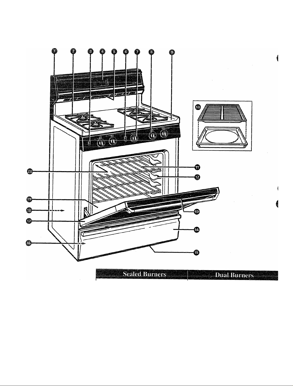
FEATURES OF YOUR RANGE
Burner Cap
/L[
// I \ W
Durner neaa
\ V—--— Drip Pan
\ \\ (nn enmo
A_L
Biirnfir Ra.esp
models)
!r>
Ij Burner
\V—
^r\
W (on some
models^
// \\\
Your range is equipped with one of the two types of surface burners shown above
—
Page 7

Feature Index (Not all models have all features. Appearance of features varies.) See page
/1
1 Backguard (on some models)
2 Surface Burners, Drip Pans (on some models) and Grates
3 Oven Lamp On/Off Switch (on some models)
4 Clock and Timer (on some models)
5 Oven Vent (located on cooktop on some models)
u £>cus.c/J3iuxi owiitii suuic uiuucia^
7 Oven Control
8 Surface Burner Controls
9 Cooktop
10 Broiler Pan and Rack
11 Oven Shelves (number of shelves varies)
12 Oven Shelf Supports 13,14
13 Air Vent in Oven Door (located at top of Oven Door)
14 Broiler Drawer or Storage Drawer (depending on model)
15 Air Intake 4, 28
16 Model and Serial Numbers (located on front frame of range,
behind either Broiler Drawer or Storage Drawer)
—
21,22
14
11,12
4,5,13, 28
12
8
23,28
IQ 9^
13-15,23
4,28
27
2,31
S'
o
c
se
p
(7Q
17 Removable Oven Door
18 Anti-Tip Device (Lower right rear comer on range back.
See Installation Instructions.)
19 Oven Bottom
20 Oven Interior Light (on some models)
NOTE: All models have standard oven interiors, except for JGBC15GER, JGBC16GEP, and
JGBC17GER which have continuous-deaning oven interiors. See Care and Cleaning for
instructions.
25
3, 30,40
23
14,24
7
Page 8
Electric Ignition Models
SURFACE COOKING
Your surface burners are lighted by electric ignition,
eliminating the need for standing pilot lights with
constantly burning flames.
In case of a power failure, you can light the surface
burners on your range with a match. Hold a lighted
match to the burner, then turn the knob to the LITE
position. Use extreme eautiGn when lighting burners
this way.
iiOi3k on nr^\17AT*
XIA UOWz YVXIWXA CU.A WXWV/ULXWCU. V VV'X
failure occurs will continue to operate normally.
Standing Pilot Models
The surface burners on these ranges have standing
pilots that must be lit initially. To light them:
1. Be sure surface burner control knobs are in
LUC Kjrr pU2>lUUli.
2. Remove the grates and lift the cooktop up
T -i-Pf-TT-rs
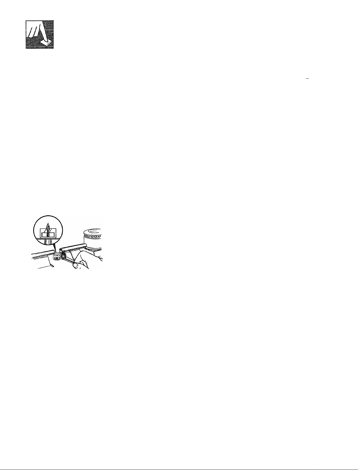
J-/1J. t" V../OW'WVXV.fXXy.
3. Locate the two pilot
nnrtc iinrl liaht f».np.h
... ^—''**
of them with a match.
The electrode of the spark igniter is exposed.
wnen one Dumer is mmea to Lims, an me oumers
« • . t . T Yri-IYI _11 a1
__________________1_____________
_
spark. Do not attempt to disassemble or clean
around any burner while another burner is on.
An electric shock may result, which could cause
you to knock over hot cookware.
NOTE: If the pilot is too high or low, you can
¿lUJUdL IL. OCC Ul^ r^VlJUOL tJLlW OUlJLClW J-^ixxxxv/x X xxwcc»
4-VkA A FKza Cnr^nr-*0 T^llt*nOf
If Necessary section of the Installation Instructions
/1 T trie ennVtnn Vniir cnrfiipp VuimPTC nrp nnv
■*F* X_zW W WX i.XXW V'V/VyXVtV/l^. JL KJ t*A C7VI.X XMV'W »
ready for use.
5. Observe lighted burners. Compare the flames
to pictures in the Problem Solver. If any flame
is unsatisfactory, call for service.
Surface Burner Controls
JNJLiuucj Luai LUiii U№ i>uiiav^& cuiyj. yjxx clx\^
marked as to which burners they control. The two
knobs on the left control the left front and left rear
burners. The two knobs on the right control the right
front and right rear burners.
efr or*o
On ranges with sealed burners:
• The smaller burner (right rear position) will give
the best simmer results.
• The right front burner is higher powered than the
others and will bring liquids to a boil quicker
(natural gas installations only).
Page 9

Before Lighiing a Burner
* If drip pans are supplied with your range, they should be used at all times.
® Make sure both srates on one side of the ranee are in olace before usine
......
—
-------------
------
9
either burner.
To Light a Surface Burner
/L
Electric Ignition Models:
Push the control knob in and
turn it to LITE. You will hear
a little “Glic-king” noise—the
sound of the electric spark
igniting the burner.
After the burner ignites, turn the
knob to adjust the flame size.
After Light ing a B urne r
® Check to be sure the burner you turned on is the one
#
you want to use.
• Do not operate a burner for an extended period
XXXXXW WXLllVXUL VUJl Ui^ gia№. Xll^ lllUdll
on the grate may chip without cookware to absorb
the heat.
® Be sure the burners and grates are cool before you
place your hand, a pot holder, cleaning cloths or
other materials on them.
Standing Pilot Model:
Push control knob in and turn it to HI position.
The burner should light within a few seconds.
After the burner ignites, turn the knob to adjust the
flame size.
Flame will be almost horizontal and will lift
slightly away from the burner when the burner
is first turned on. A blowing or hissing sound
may be heard for 30 to 60 seconds. This normal
sound is due to improved injection of gas and air
into the burner. Put a pan on the burner before lighting
it, or adjust the flame to match pan size as soon as
it liohfe япН th#» blnwitiCT nr hiccina cniinH wiTl h#a
A«. MAV TV VA AAAUUAAA^ V«- TT АЛЛ
much less noticeable.
(continued next page)
Page 10
SURFACE COOKING
(continued)
How to Select Flame Size
Watch the flame, not the knob, as you reduce heat.
The flame size on a gas burner should match the
cookware you are using.
FOR SAFE HANDLING OF
COOKWARE NEVER LET
THE FLAME EXTEND
UP THE SIDES OF THE
COOKWARE. Any flame larger than the bottom
/%-p 1C Ckr\r\ Oi^t*\/PC ir\ hpiif
C/X ULIO CU. W XO VV CtaLV-VJ. U.AAV» \JA.XXJ w w
the handle.
Top-of-Range Cookware
Aluminum; Medium-weight cookware is
recommended because it heats quickly and evenly.
Most foods brown evenly in an aluminum skillet. Use
saucepans with tight-fitting lids when cooking with
minimum amounts of water.
Cast-Iron: If heated slowly, most skillets will give
satisfactory results.
Enamelware: Under some conditions, the enamel of
some cookware may melt. Follow cookware
manufacturer’s recommendations for cooking methods.
Glass: There are two types of glass cookware—those
for oven use only and those for top-of-range cooking
(saucepans, coffee and teapots). Glass conducts heat
very slowly.
When boiling, adjust the flame so the circle it makes
is about 1/2 inch smaller than the bottom of the
cookware—no matter what the cookware is made of.
Foods cook just as quickly at a gentle boil as they do
o •ftitM/'Mic r-rfcllii-irr Knil A ViiirH hnil
at a XtXXXt./tlk3j XV^XXXll^ C/\^XX. X x. xxxgxx c/\-^xx wxwM^wk^ UJWWJI**
and cooks away moisture, flavor and nutrition. Avoid
it except for the few cooking processes that need a
vigorous boil.
When fr3dng or warming foods in stainless steel,
cast iron or enamelware, keep the flame down
lower—to about 1/2 the diameter of the pan.
When frying in glass or ceramic cookware, lower
the flame even more.
Heatproof Glass Ceramic: Can be used for either
surface or oven cooking. It conducts heat very
slowly and cools very slowly. Check cookware
manufacturer’s directions to be sure it can be used
on gas ranges.
Stainless Steel: This metal alone has poor heating
properties and is usually combined with copper,
aluminum or other metals for improved heat
distribution. Combination metal skillets usually work
satisfactorily if they are used with medium heat as the
manufacturer recommends.
Wok Cooking
(on models with sealed burners)
• We recommend that you
use only a flat-bottomed
wok. They are available at
your local retail store.
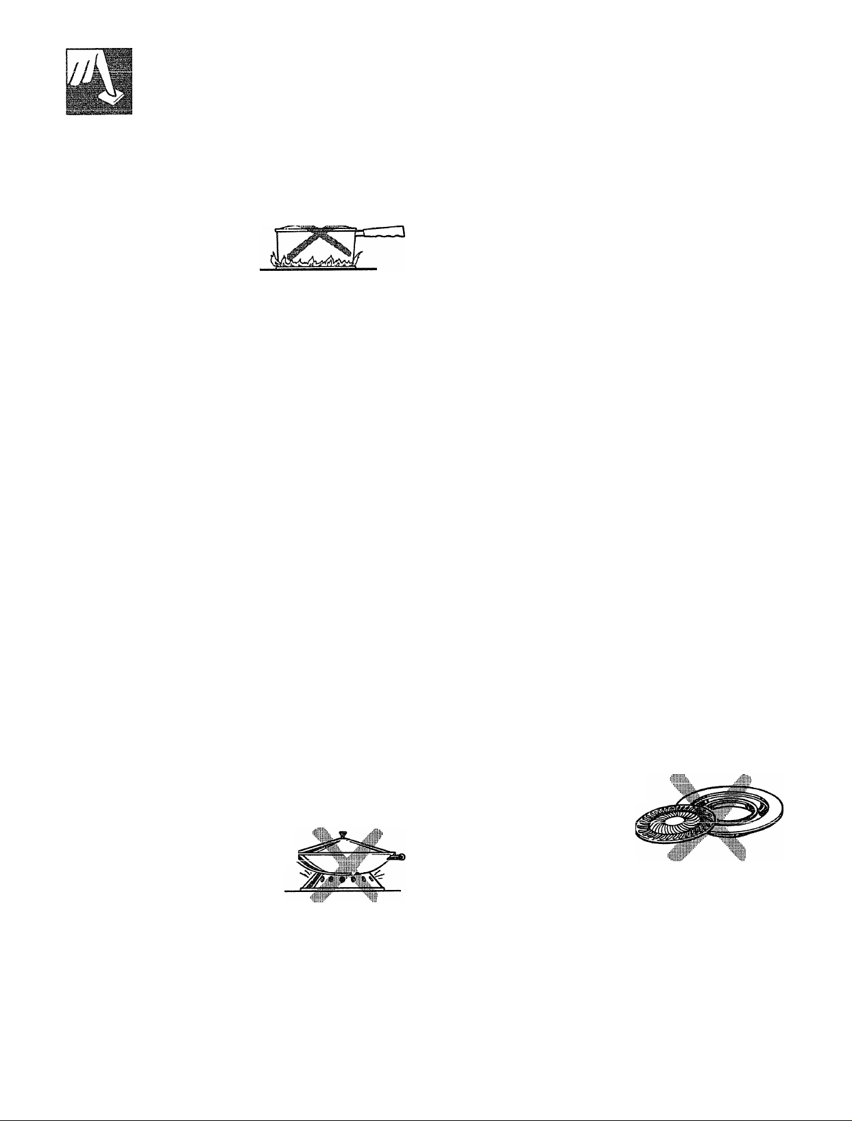
* Do not use woks that have
support rings. Use of these
types of woks, with or
VVXVXXV^XXb XXXW XXXX^ XXX
tb<a rinrr in п1яг<=»
can be dangerous. Bacing the
ring over the burner grate may
cause the burner to work improperly resulting in
carbon monoxide levels above allowable current
хш» k^uuiu uc uaiigduua tw ixwcui.ii.
Do not try to use such woks without the ring. You
could be seriouslv burned if the wok tipped over.
10
Use of Stove Top Grills
(on models with sealed burners)
Do not use stove top grills
on your sealed gas burners.
If you use the stove top
grill on the sealed gas
burner it will cause
inp.nmnlpil-p. r.nmhnsHnii
------------
r—'—
and can result in exposure
to carbon monoxide levels
above allowable current standards.
This can be hazardous to your health.
---------------------------
Page 11

' This model has an improved clock.
AiodEi-s: Oru~Y Please use this sheet in place of the instructions
in your Use and Care Guide.
>’S-Q<?e.sr Pi^
^£>'S .‘7q>c cf n 7 ' ' '
CLOCK AND TIMER
Follow ihe directions below if your range has the
dock and timer shown at the right.
HjC range clock and timer allow you to set the tuner
up 10 24 hours. You have the choice of having the
timer .sliow the lime counting down or the time of day.
In ciihcr case, the timer will signal at die end of the
timer period lo alen you ihai ihc lime is up.
CLOCK j
f _# • f if i
'ULJ
TIMER
(Appearance may vary)
To Set the Clock
NO i K: Wlicn you first piug in the range or after a
power lailure, ilie entire Cloek/Timer display will
!iu!u up= Aficr scvcni! .seconds ”SET CLOCK *
appears in the display.
1. Press the CLOCK pad.
2. Press and hold Ihe UP or DOWN pad and the lime
of day will change 10 minutes at a time. To change
the lime by single minutes, give the pads short laps.
3. Prc.ss Ihc CLOCK nnd to start the eloek-
io Change or Cancel the Timer Setting
When ihe timer is counting down, use the UP and
DOWN pad to change the remaining lime, or press
the TIMER pad to stop the timer Tlie timer cannot
be cancelled until “SETTIME” di.sappears from
tlic iiispiay.
To Set the Timer
1. Press the TIMER pad.
2. Use the UP and DOWN pads to set the timer
Short taps on the UP or DOWN pad change the
timer’s setting one minute at a time. Pressing and
ten minutes at a time. The timer can be set for a
maximum of 24 hours.
3. Press the TIMER pad to start the timer.
Ac the tirriAr r^rttinic rfnwn
4 4M« V* My V *« W
when one minute is left. After these beeps, the
display will count down in seconds. When time nins
out, a signal will sound. Press the TIMER pad to stop
the signal.
t/\ tflA 7T1D lTl/«f*A<neAC»
uiw WA AAJtVAWaawo UJI&
beeps
To Display the Clock While the Timer Is Operating
Pressing the CLOCK pad while the timer is operating
will not inicrfcrc witli the timer’s operation: the
display will change to show ihc clock, but the timer
will continue to count down and will still signal when
iiinc is up. Press the TIMER pad again to change the
display back to show the timer.
49-S33H C^cs:iJ
Page 12

CLOCK AND TIMER
Follow the directions below if your range has the
deck and timer shown at the right«
' The electronic range clock and timer allow you to set
thft im tn 0 hmirc anrJ minnf-i:»« Vr»n Uni/i» tUo
W**A*W* »-*1^ »-V U» VUJIU -r*." X. V/««X XAUVW
choice of having the timer show the time counting
down or the time of day. In either case, the timer will
signal at the end of the timer period to alert you that
the time is up.
To Set the Clock
NOTE; When you first plug in the range or after
a power failure, the entire Qock/Timer display will
light up. After several seconds “12:00” will then flash
on the display.
1. Press the CLOCK pad. “12:00” stops flashing
J 4<riT7fT« *rmi >TT7I»
anu om iiivm iiasnes on me aispiay.
2. Press and hold the UP or DOWN pad and the time
KJi ^ay will ^^iiciiigc lu iimiuLc:;» ai a umc. lu cxiarige
wr«!*! ^ A 1 i~\ «.«aI n a 4- «-•. 4*^ .«.u HP—„ ^1... ^
the time by single minutes, give the pads short taps.
iro»* Avovirmlo tr\ 04at- fKo /^Irvrfclr -fXr*
%,\J tiiw IV-U pi^dd dllU.
hold the UP pad until “3:10” appears, and then tap
the UP pad until “3:15” is displayed.
3. Press the CLOCK pad and the clock will be set. If
you do not press the CLOCK pad, the clock will
automatically be set within one minute.
__1__
__
- - .f 1
CLOCK
TiMER
SET
TIMER
jZS nn
IL. -UU
To Set the Tim er
1. Press the TIMER pad. “:00’
and “SET TD^R” flashes. "" " "
2. Use the UP and DOWN pads to set the timer.
Short taps on the UP or DOWN pad change the
timer’s setting one minute at a time. Pressing and
continuing to hold the UP pad increases the setting
five minutes at a time until one hour (“1:00”) is
disn1avp.fl. Aftpr nnp. hnnr is disnlnvpd nrpccinor
---
--------J --
----
--
and holding the UP pad increases the setting
15 minutes at a time. (Short taps on the UP and
DOWN pads will always change the setting by
1-minute increments.) The timer can be set for a
TY*IOVfrV>nrYl /^-p Q /1C Art
XXlMZkXXXXUlll \JX ^ llWUld OiiU limiut^i^.
3. To start the timer, press the TIMER pad.
Tf tflP TT\/iF?i? tliiH ic nr\f r%r*Aooix/^ tVlia timor» \i7i1T
J.X. wxxw X. JLJ.TAJL^X.V XCJ XXVXb ^XV’Ok3W\«X9 UIW VXXXIWX VVXXX
automatically start after a few seconds.
As the timer counts down, a single beep will
indicate when one minute is left. After this beep,
the display will count down in seconds. When the
timer reaches “:00,” you will hear three sets of three
short beeps, and then a single beep every 10 seconds
Pr%r* 1 A
XV/X X\./ XXXXX1IXI.WO V/X UIXUX y\J\X 011^ U1 Ul^
Clock/Timer pads.
annears nn the. disnlav
____
______
_
c
a,
o
n
o
©
E
ora
To Change or Cancel the Timer Setting
wnen the timer is counting down, use the UP and DOWN pad to change
the remaining time, or press the TIMER pad to cancel the timer function.
Thp. Hmp.r ■fnnr.Hnn rnnnnt f»p riknreA\i>A nnfil “QlnT TTA/TThD CfrvrAC Plookii-rtrt*
w*AAAAx.rw «-rw w VAX A v<-v/X X w V4 vxxxuxx \jf JL^ X. X. X.XTXJLJX^ XXMOXAXXA^
and “TIMER” appears on the display.
To Display the Time Ox Day While the Timer is Operating
Pressing the CLOCK pad while the timer is operating will not interfere
with me iimer s operaiion; me aispiay will cnange to snow the time or day,
but the timer will continue to count down and will still signal when time
is up. Simply press the TIMER pad again to change the display back to
show the timer function.
(COtliinueu neXi page)
Q
©
©4
©
11
Page 13

Bjy
Clock
CLOCK AND TIMER
(continued)
Follow these directions if your range has the dock and timer shown at
&1IC JLV OVl- Viwilk^ pUOlA il* UIV rWJllWL/ C4A1V* tui.ll It tv tllV wxxv
TVk »nfioVi 4-n fVio lrr»i^V\ an/^ Liim it* fViA t^frVlf T pf thp
knob out when the clock hands reach the correct time. Continue turning the
knob to OFF.
Timer
The Timer has been combined with the range clock.
TToo %f fr\ tir«p oil \/ruir r%r*Ar*ioA r*r%r\ViniT nr»priifmnc
It tv txixiv txxx ^vt*x j^xwxow wwxvxxx^ VXVXV**»-».
You’ll recognize the Timer as the pointer that is
different in color than the clock hands.
Minutes are marked up to 30, and hours are marked
up to 4 on the center of the clock.
To set the Timer, turn the knob to the left—without
niishina in—until the nointer reaches the number of
—-------------
minutes or hours you want to time.
At the end of the set time, a buzzer sounds to tell
you time is up. Turn the knob—without pushing
in—until the pointer reaches OFF and the buzzer stops.
USING YOUR OVEN
Before Using Your Oven
Be sure you understand how to set the controls properly. Practice removing
and replacing the shelves while the oven is cool. Read the information and
fitAo /-»« tVio noiT/ac VAfsn this hr»r»V hiinrlv whpTP vnii ran rp.fc.r tfv it
kXj^O VXl XXXV XVXXWVXXX^ VXXXk? wvx-a. xxxxxxvx^
especially during the first weeks of using your new range.
t-------------------------------------------------------
Oven Control
Your oven is controlled either by a single OVEN
CONTROL knob or by a BAKE/BROIL switch and
an OVEN CONTROL knob.
Tí* r 'iO OO ■florv^o
It will iiuiiiiaiiy ^V“:7V7 uviviv tiiw xxcuixv
comes on. After the oven reaches the selected
temperature, the oven burner cycles—off completely,
then on with a full flame—to maintain the selected
temperature.
Electric Ignition Models
The oven burner and broil burner are lighted by
electric ignition.
To light either burner, turn the OVEN CONTROL
Vr»nK tn tlni» Hi»cir#»H tAmriAriil-iim Thi» hiirnp»r chnnlH
XXXXW XV XXXV WdXXW XVXXXj^ VX XXVX«X V* A XXV l..^V«XXAWX IL.TXAX.F MXX.*.
ignite within 30-90 seconds.
After the oven reaches the selected temperature, the
oven burner cycles—off completely, then on with a
full flame—to keep the oven temperature controlled.
If your range is equipped with a separate
»9 YTlI^Vlt»
Turn switch to BAKE for all normal oven
Vj^VXCXXXVXXO
PiVOtVinlA fr»r r'r»nlrincr rrinctc nr
-
xvx vyvcxxxxj^xv; xvx vwxvxxx^ XVUI.JVL7 vx
casseroles. Only the bottom oven burner operates
when the BAKE setting is selected.
Use the BROIL setting for broiling. Only the top oven
burner operates when The BROIL setting is selected.
Power Outage
CAUTION: DO NOT MAKE ANY ATTEMPT TO
OPERATE THE ELECTRIC IGNITION OVEN
DURING^\N ELECTRICAL p6^^ FAILURE.
The oven or broiler cannot be lit during a power
failure. Gas will not flow unless the glow bar is hot.
If the oven is in use when a power failure occurs, the
oven burner shuts off and cannot be re-lit until power
is restored.
12
Page 14
Standing Pilot Models
гяпаАС efimHinn- nilr\tc thot miict- Kia
A AIMTW bJ7«.UAAV»XXA^ VAAC4lr AlAV«^OL C/W
lit initially.
To light the oven pilot!
1. Be sure the OVEN CONTROL knob is in the OFF
position.
2. Open the broiler door and remove the broiler pan
and rack. This will make it easier for you to reach
inside the broiler compartment.
Oven Vente
'X T7tT^H fKo r\\TCkr\ rtf fViA
X xjiiv^ tlxw vyvwii pv/iL ai* uii^
back of the broiler
compartment. The long tube,
running from front to back, is
the oven burner. The pilot port
is at the back about one inch
below the burner.
•«* LJ Miig a luiig uiaiv.^u ux xxxax^xx
holder, reach in and light the oven pilot.
О
О
s
a
The oven is vented through duct openings at the rear
of the cooktop. See Features section. Do not block
these openings when cooking in the oven—it is
important that the flow of hot air from the oven and
fresh air to the oven burners be uninterrupted.
»The vent openings and
nearby surfaces may
become hot. Do not
touch them.
• Do not leave plastic
items on the cooktop—
they may melt if left too
close to the vent.
Oven Shelves
The shelves are
designed with
OtUp-IUWJVa ^KJ
when placed
correctly on the
shelf supports,
they will stop
before coming
/-*r\mrvliaf/alx/ ruif rvF
the oven and will
not tilt when you
are removing food from them or placing food on
them.
When placing cookware on a shelf, pull the shelf out
to the “stop” position. Place the cookware on the
SUCH, men siiuc me sneii uiie*. imu me uveii. inis wui
eliminate reaching into the hot oven.
V/LiX VX
:^4.^ ai__
_ _ _
...;n
• Handies of pots and pans on the cooktop may
become hot if left too ciose to the vent.
• Metal items will become very hot if they are left
on the cooktop and could cause burns.
• Do not leave any items on the cooktop. The hot air
from the vent may ignite flammable items and will
increase pressure in closed containers, which may
cause them to burst.
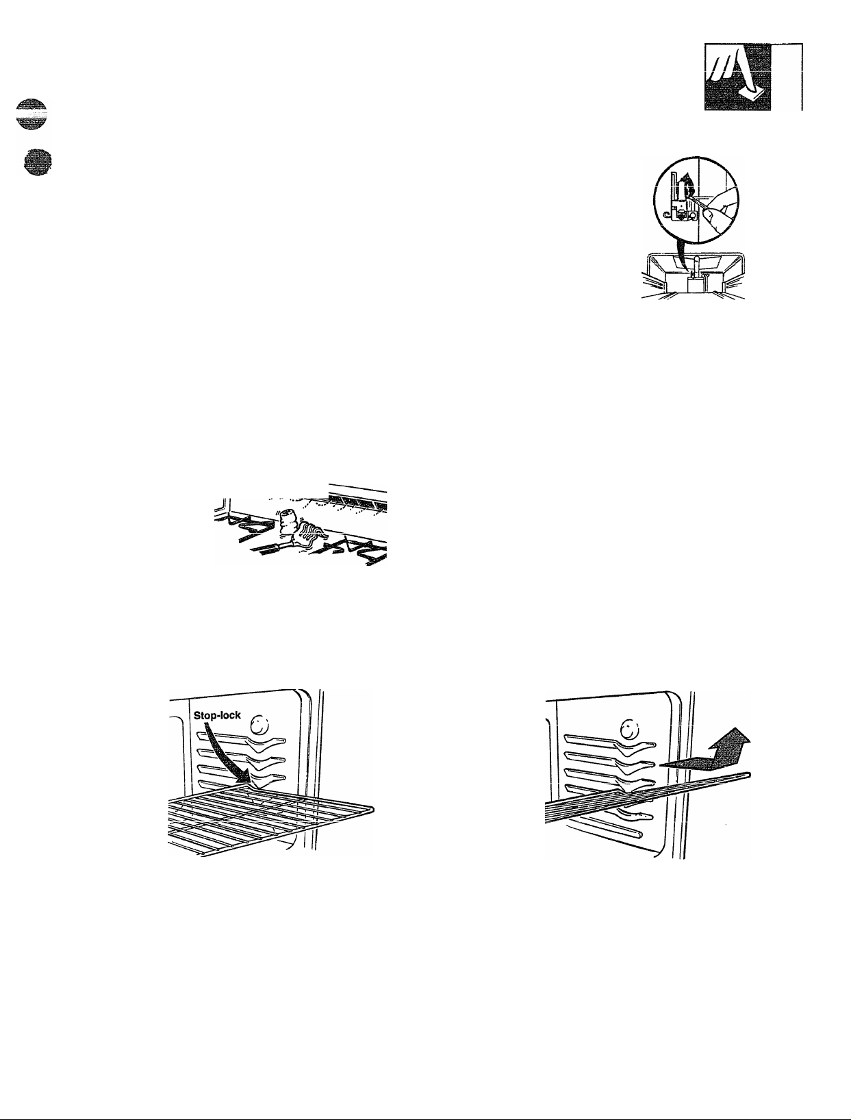
To remove a
shelf from the
oven, pull it
toward you, tilt
front end upward
and pull shelf out.
To replace, place
shelf on shelf
support with stop-
locks (curved
shelf) facing up and toward rear of oven. Tilt up front
and push shelf toward back of oven until it goes past
“stop” on oven wall. Then lower front of shelf and
push it all the way back.
(continued next page)
9
5*
GfQ
m
©
a
13
Page 15
ITTW
m
USING YOUR OVEN
i'continuedi
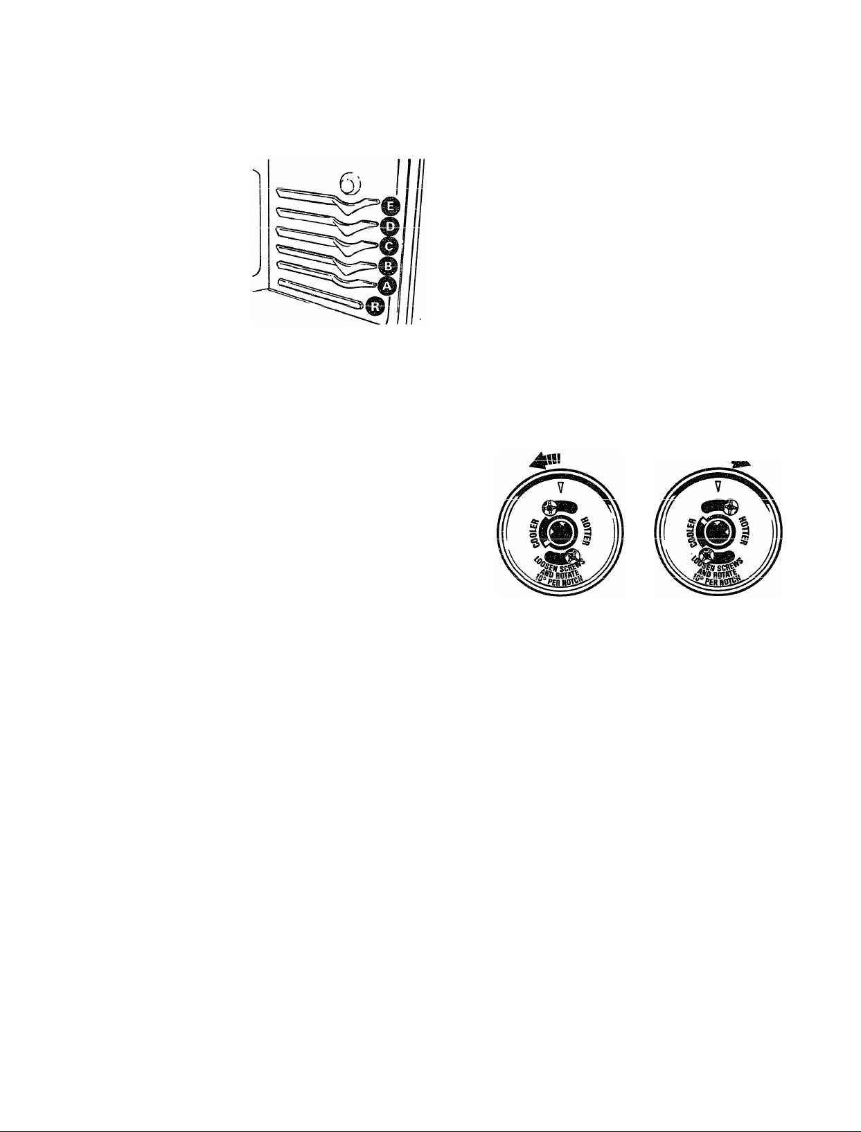
Slielf Positìoes
The oven has five shelf
supports for normal
baking and roasting
identified in this
iiiustration as A
(bottom), B, C, D and E
(top). It also has a
special low shelf
position (R) for roasting
extra large items, such
as a large turkey—the
shelf is not designed to slide out at this position. Shelf
positions for cooking are suggested on Baking and
Roasting pages.
Oven Temperature Adjustment
me Lcmpcicuuic ^»ciceieu uii uie uiciiJiiu&uii vxiai
determines the average of the maximum and minimum
temperatures reached during the cycling of the oven
burner. The thermostat control in your new oven has
been carefully designed and manufactured to provide
accurate temperatures. If your new oven is replacing
one you have used for several years, you may notice
a difference in die degree of browning or the length of
time required when using your favorite recipes. This
is because oven temperature controls have a tendency
to “drift” over a period of years.
Before attempting to have the temperature of your
new oven changed, be sure you have carefully
followed the baking time and temperature
recommended by the recipe. Then, after you have used
the oven a few times and you feel the oven is too hot or
too cool, there is a simple adjustment you can make
yourself on the OVEN CONTROL knob.
Oven Moisture
As your oven heats up, the temperature change of the
air in the oven may cause water droplets to form on
the door glass. These droplets are harmless and will
evaporate as the oven continues to heat up.
Oven Light (on some models)
The oven light comes on automatically when the door
is opened. Some models have a switch on the lower
control panel that allows you to turn the light on or off
when the door is closed.
Pull the knob off the range and look at the back side.
To make adjustment, loosen (approximately one turn),
but do not completely remove, the two screws on the
back of the knob. With the back of the knob facing
you, hold the outer edge of the knob with one hand
and turn the front of the knob with the other hand.
To raise the oven temperature, move the top screw
toward the right. You’ll hear a click for each notch
you move the knob. To lower the temperature, move
the top screw toward the left. Each click will change
the oven temperature approximately 10°F. (Range is
plus or minus 60°F. from the arrow.)
We suggest that you make the adjustment one click
from the originai setting and check oven performance
before making any additional adjustments.
After the adjustment is made, retighten screws so they
are snug, but be careful not to overtighten. Reinstall
knob on range and check performance.
14
Page 16

How To Set Your Range For Baking
BAKING
|1. To avoid possible burns, place the shelves in the
correct position before you turn the oven on.
2. Close oven door. If your model has a separate
BAKE/BROIL switch, turn it to BAKE. Turn
OVEN CONTROL knob to desired temperature.
Oven Shelves
Arrange the oven
shelf or shelves
in the desired
locations while
the oven is cool.
The correct shelf
position depends
on the kind of
food and the
browning desired.
As a general rule,
niace most foods in Iho middip of thp nvpn nn plthpr
the second or third shelf from the bottom. See the
chart for suggested shelf positions.
3. Check food for doneness at minimum time on
recipe. Cook longer if necessary. Turn OVEN
CONTROL knob to OFF and remove food.
For best baking results, follow these suggestions:
Type of Food
Angel food cake
JL^.LOWUXI.0 \JL XXlUXXlXld
r\f ■ mivPPÎ'Mr'
Cookies or cupcakes
Brownies
T
wx wMxvwo
Bundt or pound cakes
Pies or pie shells
THrr\'7/>n r>ii»C
X XWXjWXX ^XWO .
Casseroles
Shelf Position
A
t> r»
U yjk
BorC
BorC
T3 r'
JJ v^x
AorB
B or C
A (r\-r\
XTl \^V/XX
BorC
r|
K
iBBi«
p
Q
«
p
Preheating
Preheat the oven if the recipe calls for it. Preheat
means bringing the oven up to the specified
temperature before putting in the food. To preheat, set
thp nvpn at thp prvrrppt tAtnr\pr'otnfia_
■
....
.............
Mk OfXXW Nx’V.iFXX«
■
............
.............
higher temperature does not shorten preheat time.
Preheating is necessary for good results when baking
cakes, cookies, pastry and breads. For most casseroles
and roasts, preheating is not necessary. For ovens
without a preheat indicator light or tone, preheat 10
minutes. After the oven is preheated place the food
in the oven as quickly as possible to prevent heat
from escanina.
_0 i.
Roasting
AorB
Pan Piacement
For even cooking and proper browning, there must be
enough room for air circulation in the oven. Baking
results will be better if baking pans are centered as
much as possible rather than being placed to the front
or to the back of the oven.
Pans should not touch each other or the walls of the
oven. Allow 1 to 1/4 inch space between pans as well
as from the back of the oven, the door and the sides.
If you use two shelves, stagger the pans so one is not
directly above the other.
(continued next oaee)
E
5'
CTO
15
Page 17

BAKING
(continued)
Baking Guides
When using prepared baking mixes, follow package recipe or instructions
for best baking results.
Cookies
When baking
cookies, flat cookie
sheets (without
sides) produce
better-looking
cookies. Cookies
baked in a jelly roll
nan ichnrt «iHpc p11
around) may have
darker edges and pale or light browning may occur.
Do not use a cookie sheet so large that it touches the
walls or the door of the oven.
For best results, use only one cookie sheet in the oven
at a time.
/'
<S!> ¿>
f \
J \
&
o
Pies
For best results, bake pies in dark, rough or dull
pans to produce a browner, crisper crust. Frozen
pies in foil pans should be placed on an aluminum
cookie sheet for baking since the shiny foil pan reflects
heat away from the pie crust; the cookie sheet helps
JL^Laili XL.
Alimiiniim FoO
Never cover a shelf
entirely with a large
cookie sheet or
aluminum foil. This
will disturb the heat
circulation and results
in poor baking. A
smaller sheet of foil
may be used to catch a
spillover by placing it
on a lower shelf several inches below
the food.
Cakes
When baking cakes, warped or bent pans will cause
uneven baking results and poorly shaped products.
A cake baked in a pan larger than the recipe
recommends will usually be crisper, thinner and drier
than it should be. If baked in a pan smaller than
XWWVfXXXXlXV'XIV&W’Uy XL XXICX^ L/W UXAVXWXWV/V7XVWLX LUILX L/MLLWX XXACXJT
overflow. Check the recipe to make sure the pan size
used is the one recommended.
Baking Fans
Use the proper baking pan. The type of finish on the
pan determines the amount of brownmg that will occur.
® Dark, rough or dull pans absorb heat resulting in a
UXV/WXlVly vxxopwx VXUOt. U.XXO pxwa.
TToA fVlio
«Shiny, bright and smooth pans reflect heat, resulting
iti a mrkrA Af^Mnato Km^i/niTUT ixnA
XAA M AAJLV/XW V4V/AAX/MVW 1./A VT TT AAAAA^. 'Sm’^VAAVV'UI MAA^
cookies require this type of pan.
® rrlac« hakina rlichf».« nlsn nhsnrh hf»nt Whf»n hakinor
-----
¿5
--------------------------
------------
'
----
----------
--------------
Q
in glass baking dishes, lower the temperature by
25 °F. and use the recommended cooldng time in
the recipe. This is not necessary when baking pies
or casseroles.
16
Don’t Peek
Set the timer for the estimated cooking time and do
not open the door to look at your food. Nlcst recipes
provide minimum and maximum baking times such
as “bake 30-40 miniites.”
DO NOT open the door to check until the minimum
time. Opening the oven door frequently during
cooking allows heat to escape and makes baking
times longer. Your baking results may also be
Page 18

TiiT^ A ¿nrri'm.Tin
7^
Roasting is cooking by dry heat. Tender meat or
poultry can be roasted uncovered in your oven,
j Roasting temperatures, which should be low and
steady, keep spattering to a minimum.
The oven has a special
low shelf (R) position
just above the oven
bottom. Use it when
extra cooking snace if?
-------^ ------
—
needed, for example,
when roasting a large
turkey. The shelf is not
designed to slide out at
tVlic r»r»citirkr«
Roasting is really a baking procedure used for meats.
Rna.<?tina is p.asv in«f follow fhpcp ctpoc*
1. Position oven shelf
at ('B') oosition for
-----N-------
y X
---------------------------------------
small size roast
(3 to 5 lbs.) and
at (R) position for
larger roasts.
z. unecK me weignt
of the meat. Place
the- meat fat-side-up
or the poultry breast-side-up on the roasting rack in
a shallow pan. The melting fat will baste the meat.
Select a pan as close to the size of meat as possible.
(Broiler pan with rack is a good pan for this.)
Line broiler pan with aluminum foil when using pan
for marinating nnnkina with fruits fnnHno hpnvilv
-------------
---------------------^-------
---------------
O ***-*VL.», T A.iJ
cured meats, or basting food during cooking. Avoid
spilling these materials inside the oven or inside the
oven door.
3. If your model has a separate BAKE/BROIL switch,
turn it to BAKE. Turn die OVEN CONTROL knob
to desired temperature. Check the Roasting Guide
fnr tPirmpratiirAc onrl r*/-\i-^lr5r*rr
4. Most meats continue to cook slightly while
standing after being removed from the oven.
Recommended standing time for roasts is 10 to 20
minutes. This allows roasts to firm up and makes
them easier to carve. Internal temperature will rise
about 5° to 10°F. If you wish to compensate for
vwxAtpwxcAWUJLW ixow, LIl^ luadt Ul^ UYCil
r/3» ««y-vr» o4- 4-t-«
when its internal temperature is 5° to 10°F. less
than temperature shown in the Roasting Guide.
NOTE: Remember that food will continue to cook in
the hot oven and therefore should be removed when
the desired internal temperature has been reached.
w
E
T'rozen Moasis
• Frozen roasts of beef, pork, lamb, etc., can be started
without thawing, but allow 15 to 25 minutes per
pound additional time (15 minutes per pound for
roasts under 5 pounds, more time for larger roasts).
»Thaw most frozen poultry before roasting to ensure
even doneness. Some commercial frozen poultry can
Hp prinlrprj cnpf*pccflin\7 \x;ifrir\nt tUoil/i«!-» Tni-vUz-vii,
i-rw x.'wv.rxvwv«- VVXbJlAV/UW W11€A VV XAJl^a X VyilV W
directions given on package label.
Dual Sh elf Coo king
This allows more th^ one food to be cooked at the
same time. For example: While roasting a 20-lb.
turkey on shelf position R, a second shelf (if so
equipped) may be added on position D so that
scalloped potatoes can be cooked at the same time.
Calculate the total cooking time to enable both dishes
to complete cooking at the same time. Allow 15-20
minutes of additional cooking time for the potatoes.
17
PS
©
c»
a
QTQ
Page 19

Questions and Answers
А r^rBTÏT®.T^^
(continued)
Q. Is it necessary to check for doneness with a
meat thermometer?
A. Checking the finished internal temperature at the
completion of cooking time is recommended.
*Tjp»mr%<arotiiir/ac Ofia cVirMi/n 4r» l?/\Qcti”nrr r7liiir1/a
XWXJtXj^WXdUC&XWO (XXV/ OXXV/W XX XXX xvv/cxoxxxx^ V^XXXVXV/« X v^x
roasts over 8 lbs., check with thermometer at half
hour intervals after half the time has passed.
Q. Why is my roast crumbling when I try to
carve it?
A. Roasts are easier to slice if allowed to cool 10 to
20 minutes after removing from oven. Be sure to
cut across the grain of the meat.
Q, Do I need to preheat my oven each time 1 cook
a roast or poultry?
A. It is unnecessary to preheat your oven.
Q. When buying a roast, are there any special tips
that would help me cook it more evenly?
A. Yes. Buy a roast as even in thickness as possible,
or buy roiled roasts.
Q. Can I seal the sides of my foil “tent” when
roasting a turkey?
A. Sealing the foil will steam the meat. Leaving
—1.^
XL UXX2>COXC:i
the meat.
ROASTING GUIDE
1^'pe
Oven
Temperatu;^
Til/V Vt АП AC C
Meat 3 to 5 lbs. 6 to 8 lbs.
Tender cuts; rib, high quality sirloin
tip, rump or top roundf
Я25° Rare: 24-35 18-25 140°-150°*
Medium:
Well Done: 39-45 31-33 170°-185°
О oi on oa
Medium:
Well Done: 30-35 28-33 170°-185°
Veal shoulder, leg or loinf
Pork loin, rib or shoulderf
325“
325° Well Done: 35-45 30-40 170°-180°
Well Done: 35-45 30-40 i/0”-i50”
Ham, precooked 325° To Warm: 18-23 minutes per pound (any weight)
Poultry 3 to 5 lbs. Over 5 lbs.
Chicken or Duck
325°
Chicken pieces 350“
Well Done: 35-40
Weil Done: 35-40 185°-190°
Turkey 325° Well Done:
Approximate Roasting Time
in Minutes per Pound
35-39
25-31 150°-160°
nrAlYmAVVQTllWQ ®
Ж V>«AA^VX CCXUX V/
1ЛПО КПО*
25-30 24-28 150°-160°
115°-125°
30-35 185°-190°
10 to 15 lbs. Over 15 lbs. In thigh:
16-22
12-19 185°-190°
Internal
tFor boneless rolled roasts over 6 inches thick, add 5 to 10 minutes per pound to times given above.
*The U.S. Department of Agriculture says “Rare beef is popular, but you should know that cooking it to only 140°F. means
some food poisoning organisms may survive." (Source: Safe Food Book. Your Kitchen Guide. USDA Rev. June 1985.)
18
Page 20

How to Broil
BROILING
l/A
Broiling is cooking food by direct heat from above the
food. Your range has either a broiler in the oven or a
compartment below the oven for broiling. A specially
designed broiler pan and rack allows dripping fat to
drain away from the foods and be kept away from the
hlOrH hpaf nf fVl/» O-QO flom/a
*•■-»■¿5** XXCUJLX^«
Both the oven and broiler compartment doors (on
some models) should be closed during broiling.
Depending on whether your range is equipped with a
senarate broiler drawer or is enninned fnr in_nvf»n
_
-------------------------- -----
------------
-----------
» .W.X*
broiling, you can change the distance of the food from
the heat source by positioning the broiler pan and rack
on one of the oven shelves or one of the three shelf
positions in the broiler compartment—(bottom of
wvxxx|-f*xxfcxxxv/xxxy, \^XXXX\X\XX^y CU.1U
or%rl (T^
1. Preheating the broiler or oven is not necessary and
can produce poor results.
2. If meat has fat or gristle near the edge, cut vertical
slashes through it about 2 inches apart, but don’t
cut into meat. We recommend that you trim fat to
prevent excessive smoking, leaving a layer about
1/8 inch thick.
'X Arronrro «•^/>1^’ rt*^A
x-xxxcxxx^v v/ii xavjt^ OUU pU2>IUUll UlC UXUUCI \JiXll
on the appropriate shelf in the oven or broiling
compartment. Placing food closer to flame
increases exterior browning of food, but also
increases spattering and the possibility of fats and
meat juices igniting.
4. Close the oven or broiler door.
5. Turn OVEN CONTROL knob and BAKE/BROIL
switch (on models so equipped) to BROIL.
6. Turn most foods once during cooking (the
exception is thin fillets of fish; oil one side, place
thaf cidi» dm»/n
«.XXMV vxv TT XX V/XX vxv/xxvx XCXVXN. CtXXWX VV/V/JV WILllV^UL
turning until done). Time foods for about one-half
the total cooking time, turn food, then continue to
cook to preferred doneness.
7. Turn OVEN CONTROL knob to OFF. Remove
broiler pan from oven and serve food immediately.
Leave pan outside the oven to cool.
Ф
S
OTQ
Use of Aluminum Foil
You can use aluminum foil to
Une your broiler pan and
broiler rack. However, you
must mold the foil tightly to
the rack and cut slits in it just
.
Л
like the rack.
witnout the slits, the foil will prevent fat and meat
juices from draining to the broiler pan. The juices
rniild hpirnmp. hnt pnnnoh to mtnh on firi» Tf xion An
w*^xx tv WMX.WXX V/XX XXXV'« XX y \J\Jl \^\J
not cut the slits, you are frying, not broiling.
Questions & Answers
Q. When broiling, is it necessary to always use a
rack in the pan?
A. Yes. Using the rack suspends the meat over the
pan. As the meat cooks, the juices fall into the pan,
thus keeninff meat drier. Tniees яге nrnteeted bv tbp*
" X------C?
---------
----------- 'V>' L.XXW
rack and stay cooler, thus preventing excessive
spatter and smoking.
Q. Why are my meats not turning out as brown as
they should?
A. Check to see if you are using the recommended
shelf position. Broil for longest period of time
indicated in the Broiling Guide. Turn food only
once during broiling.
Broiling Tips
1. Always use broiler pan and rack that comes with
2. For steaks and chops, slash fat evenly around
Q. Should I salt the meat before broiling?
A. No. Salt draws out the juices and allows them to
r\\7Ck-r% Tf 1C /4irxci4‘r\ «n.^«.1 ^
Jvfwxx wvxi« xw xo tU IimmiUZiC »IllUlU.lIg cUlU
spattering by trapping juices in the shielded lower
part of the pan.
outside edges of meat. To slash, cut crosswise
through outer fat surface just to the edge of the
meat. Use tongs to turn meat over to prevent
piercing meat and losing juices.
evaporate. Always salt after cooking. Turn meat
with tongs; piercing meat with a fork also allows
jwxvvu X\J vviitiii UlUimig puuiuy UT ilMi,
brush each side often with butter.
(continued next page)
19
Page 21

BROILING
Models without
Broiler Compartment
tjuantity and/or
Food
X^AW£l
Ground Beef
Beef Steaks
Rare
Medium
Well Done
T\ 1 i T> 1A . /C 'T T> in / n ClcoK fot
K.are
Medium
Well Done
Chicken
Bakery Products
Bread (Toast) or
Toaster Pastries
English Muffins
Lobster Tails
Fish
Ham Slices
Precooked
tr*. «
rorK i^nops
Well Done
Lamb Chops
Medium
Wall rirtno n
TVVi/Al
Medium
Well Done
Wieners
similar precooked
sausages, bratwurst
Thickness'
1 n IK /oKanf Q r ■^1/ 3 R
A/^ AL/. ^CAI^V/VAA
thin slices)
1 lb. (4 patties)
1/2 to 3/4 in. thick
1 in. thick
(1 to IK lbs.)
1 m. iniuK.
(2 to 2K lbs.)
1 whole
(2 to 2K lbs.),
split lengthwise
2 to 4 slices
1 pkg. (2)
2, split
2 to 4
(6 to 8 oz. each)
1-lb. fillets
'i iA 1 iri
1/^ lO UL in. iniCK
1 in. thick
¿, 1,1//. in. UUCKj
2 (1 in. thick),
about 1 lb.
2 (1 in.),
2 (IK in.),
about 1 lb.
1-lb. pkg. (10)
Oven Sheif
Position
C
B 9
B
B
D
B
B
B
c
C
c
B 5
C
JO
B 13
B 8
B
B
c
1st Side
Minutes
10-11
12
13 8-9
l\J
12-15
25
30-35
2- 3
3- 5
13-16 Do not
t A A C "D 1 A A C Cl rtoU
LU
10
10
17
2nd Side
Minutes
4-5
5-6
u- /
9-12
16-18
25-30
1/2-1 C
turn over.
8
9-12
A-1
4-6
12-14 B
6
1-2
Broiler Sheif
Position
7
5
8
10
Models with
Broiler Compartment
_
] Cl* J _
isi Side
Minutes
3K
A
B 9
B
A
JLA, XV/
B
A
A
C
A 13-16 Do not
B,C
B 8 8
J3
B 13
B
R
B 10 4-6
B,C
10-11
12
13
12-15
25
30-35
2- 3
3- 5
5 5
lU
8
10 10
17
6 1-2
^nu oiue
Minutes
4-5
5-6
b-y
10-12
16-18
25-30
1/2-1
turn over.
*1-^
9-12
4-7
12-14
Comments
3
.Arrange in single layer.
Space evenly. Up to 9
patties take about same
time.
Steaks less than 1 inch
7
thick cook through before
browning. Pan frying is
recommended.
Reduce times about 5 to
10 minutes per side for
cut-up chicken. Brush
each side with melted
butter. Broil skin-sidedown first.
Space evenly. Place
English muffins cut-sideup and brush with butter
if desired.
Cut through back of shell
and spread open. Brush
with melted butter before
broiling and after half of
time.
Handle and turn very
GOIC^IUIA^. XJlUaiA WAiXl
lemon butter before
broiling and during
1
_
uiumiig li uc£>ucu.
Preheat broiler to
increase browning.
Increase 5 to 10
minutes per side for
inch thick or home cured.
oxadii lai.
Slash fat.
If desired, split sausages
in half lengdiwise; cut
into 5- to 6-inch pieces.
Page 22

CARE AND CLEANING
ггорег саге ana Cleaning are important so your range win give you efficient
and satisfactory service. Follow these directions carefully in caring for it to
‘ elo assure safe and oroner maintenance.
BE SURE ELECTRICAL POWER IS DISCONNECTED BEFORE
CLEANING ANY PART OF YOUR RANGE.
Seaied Burner Assemblies (on some models)
CAUTION: DO NOT OPERATE THE
BURNER WITHOUT ALL BURNER
PARTS AND DRIP PANS (IF SO EQUIPPED)
IN PLACE.
■Grate
Burner Cap
Burner Head
Drip Pan
(on some models)
Burner Base
f' I hi» i3 0 0<»ml^lii»c ctir»nia 1^0 /-»l/aonarl ttirkf/-»!!/rl-ilTr
JL AjLWJL UOOW’XXJ.i./XJ.W'O L/W ^AWCilXW'Vi LiIV.^X V./14-^XXX^
after spillovers.
Turn all cnntrnls OPF hefnrp mmnvincT hnmi»r narlc
and drip pans (if so equipped).
The burner grates, caps, burner heads and drip pans
(if so equipped) can be lifted off, making them easy
to clean.
The electrode of the Electrode
spark igniter is
exposed. When
one burner is turned
to LITE, all the burners
spark. Do not attempt to
disassemble or clean around any burner while
another burner is on. An electric shock may result,
which could cause you to knock over hot cookware.
Dual Burners (on some models)
On models with dual burners, the cooktop lifts up for
easy access.
The holes in the surface burners of your range must be
kept clean at all times for proper ignition and an even.
nnbiomr%iat*i3irÌ “floTVid
VAAJU.AC4JIAXJ^WXWV4. XXCU.XXW
You should clean the surface burners routinely,
p.snp.p.liillv ilftPT hilH Cnill/Y^^rfaro nrMilH r*lr\rr tViocA
holes. Wipe off surface burners. If heavy spillover
occurs, remove the surface burners frohi range.
Burners lift out for cleaning. Lift up the cooktop and
then lift out the surface burners.
To remove bumed-on food, soak the surface burner in
a solution of mild liquid detergent and hot water. Soak
tVlA Cnt^Qr*d Kll-rrior* on on
VXAW OMXXCXWW I./UXX1WX XV/X ^\J XVF XliXIiUlC^d. X'Ul XIJIUIC
stubborn stains, use a cleanser like Soft Scrub® brand
or Bon Ami® brand. Rinse well to remove any traces
of the cleanser that might clog the surface burner
openings. Do not use steel wool because it will clog
the surface burner openings and scratch the surface
hnmPTC Tf tlli»
a toothpick.
Befnrft niittine thf*. snrfnrp hnmpt* hiir*lr diot"#» r»nt
---
----
K.r*«A.x«xw ^v»xxxvx k^XXMXVW V/UX
excess water and then dry it thoroughly by setting it in
a warm oven for 30 minutes. Then place it back in the
range, making sure it is properly seated and level.
Grate
T WXk.7^ TTXXXV'XX V>V/«XX\X WXW^ UXWOV
XX VXAW xx%.rxwi^ crwwv/xxxw VX\^g^V/KX) VXWCUl LilVXii WlUl
(continued next page)
W
w
Ó
1Ш»
iSa
0
CIQ
О
s.
a
ft
21
Page 23

CARE AND CLEANING
(continued)
Biirner Caps (on sealed burners only)
Lift off when cool. Wash burner caps in
hot, soapy water and rinse with clean
water. If desired, soak up to 30 minutes
and scour with a plastic scouring pad to remove
bumed-on food particles. Dry them in a warm oven or
with a cloth—don’t reassemble them wet.
Burner Heads (on sealed burners only)
The holes in the burners of your range,
and the spark electrodes, must be kept
clean at all times for proper ignition
and mi even, unhampered flame.
You should clean the burner heads routinely, especially
after bad spillovers, which could clog these holes.
\X71
_
Wipe uii Duraer neaas. ii neavy spiiiover occurs,
remove burner heads from range.
rvciiiuvc uic uuiiicjL gxctic aiiu uumci t^ctp. xxicii lui uic
u,,™, — —
burner head straight up.
*TV\ t*drV»r\T70 o/^olr
x\j XWXXJLV./VW i.v^wvA, ^KJCLPk. CJUW' ll&au-
upside-down in a solution of mild liquid detergent and
hot water. Soak the burner head for 20 to 30 minutes.
If the food doesn’t rinse off completely, scrub it with
soap and water and a soft brush or plastic scouring pad.
______] u____
___
— rpi
___
ii- _
Burner Base
(on seaiea Dumers only)
The burner base (the part of the burner
fastened to the cooktop) may be
cleaned with a soft brush and a mild
plpilTlCPr i»n rp>oi/^nAO frr»m
.'XWUA.J. CXXX XV/V/VX XWt^XVXVXWi.? XXV/JL.&X
around spark electrode. Do not use steel wool; small
bits of steel wool will short out the electrode. Rinse
well.
For more stubborn stains, use a cleanser like Soft
Scrub® brand or Bon Ami® brand. Rinse well to
remove any traces of the cleanser that might clog the
burner openings. Do not use steel wool because it will
clog the burner openings and scratch the burners. If
the holes become clogged, clean them with a toothpick.
Before putting the burner head back, shake out excess
water and dry it thoroughly by setting it in a warm
oven for 30 minutes. Then place it back in the range,
making sure the pin in the burner base goes in the
hole in the burner head, and that the burner heads are
properly seated and level.
Orip Fans (on some models)
Remove the grates
and lift out the drip
pans. Drip pans can
be cleaned in
dishwasher or by
hand. Place them in a
covered container (or
plastic bag) with 1/4- cup ammonia to loosen the soil.
Then scrub with a soap-filled scouring pad if necessary.
Burner Grates
Lift out when cool.
Grates should be
washed regularly
and, of course,
after spillovers.
Wash them in hot, soapy water and rinse with clean
water. After cleaning, dry them thoroughly by putting
them in a warm oven for a few minutes. Don’t put the
grates back on the range while they are wet. When
replacing the grates, be sure they’re positioned
securely over the burners.
To get rid of bumed-on food, place the grates in a
covered container (or plastic bag) with 1/4 cup
ammonia to loosen the soil. Then scrub with a
soap-filled scouring pad if necessary.
Although they’re durable, the grates will gradually
lose their shine, regardless of the best care you can
give them. This is due to their continual exposure to
high temperatures.
Do not operate a burner for an extended period of
time without cookware on the grate. The finish on the
grate may chip without cookware to absorb the heat.
22
Page 24

Cooktop Surface
II—
---------- /
1 1
—^
To avoid damaging the porcelain enamel surface of
the cooktop and to prevent it froni beeouung dull,
clean up spills right away. Foods with a lot of acid
(tomatoes, sauerkraut, fruit juices, etc,) or foods with
high sugar content could cause a dull spot if allowed
to set.
When the surface has cooled, wash and rinse. For
other spills such as fat spatterings, etc., wash with
soap and water once the surface has cooled. Then
rinse and polish with a dry cloth.
Lio noi store iiammaDie maienais in an oven or
llCrt \Jl UOU V/^XliL/UOtJLUlW
materials, gasoline or other flammable vapors and
liquids in the vicinity of this or any other appliance.
porcelain
To make cleaning easier, protect the oven bottom
from excessive spillovers by placing a cookie sheet
on the shelf below the shelf you are cooking on. You
can use aluminum foil if you do not cover the whole
shelf. This is pariicuiarly important when baking a
fruit pie or other foods with a high acid content. Hot
fruit fillings or other foods that are highly acidic
(such as milk, tomatoes or sauerkraut, and sauces
with vinegar or lemon juice) may cause pitting and
damage to the porcelain enamel surface and should
be wiped up immediately. Take care not to touch hot
nnrtinn nf nvp.n
I—
-----------------
Tf O /A«-»
XX a ispxxxv/v^x vxwi^ux \jii uiw axixxw
“
the oven to cool first. You can then clean the oven
bottom with soap and water, an abrasive cleanser or
scouring pads.
Broiler Pan and Rack
/-vitci uiuuiiig, icmuvc uic uiuiici
pan and rack from the oven.
Remove the rack from the pan.
Carefully pour out the grease in
the pan into a proper container.
If food has burned on, sprinkle
the rack with detergent while hot
and cover with wet paper towels or a dishcloth. That
way, bumed-on foods will soak loose while the meal
it' Hp>inOr CAt*\/P>r} WcIcVt cr>r»lir if ni'r'P^CCtiri/ Pincp» CinH
Jti.T l.yWJUUl^ T T 7 AJk J.XWWWkJWU ^ * JL^XXXk.yV MXXVX
dry. The broiler pan and rack may also be cleaned in a
.-i* washer. Do not store a soiled broiler pan and rack
anywhere in the range.
Oven Shelves
oiicivcd wall uc; uicoiicu uy
hand using soap and water or
with an abrasive cleanser.
After cleaning, rinse the
shelves with clean water and
dry. To remove heavy,
burned-on soil, you may use
onniirinfr r^arlo A*Pt-<af
OV'V/iJ.JL
scrubbing, wash with soapy
water, rinse and dry.
(cOrUinUcd n€Xt JJU^b)
23
Page 25

CARE AND CLEANING
('continued^
Oven Lamp Replacement (on some models)
CAUTION: Before replacing your oven bulb,
disconnect electrical power to the range at the
main fuse or circuit breaker panel. Be sure to let
the lamp cover and bulb cool completely.
The oven lamp (bulb) is covered with a removable
glass cover that is held in place with a bail-shaped
'Tfc
Wire. JK.emove oven aoor, ii aesireu, lo reaen cover
_________________________ J
easily.
TV.
JLU rCllIUYCi
1. Hold hand under cover so it doesn’t fall when
VTXtXX XXXX^WXO \JX. dCXXXXW XICXXXVX) xxxxxxx^ puoxx
back wire bail until it clears cover. Lift off cover.
DO NOT REMOVE ANY SCREWS TO
REMOVE COVER.
2. Do not touch hot bulb with a wet cloth. Replace
bulb with a 40-watt household appliance bulb.
To replace cover:
1. Place it into groove of lamp receptacle. Pull wire
bail forward to center of cover until it snaps into
place. wTien in place, wire holds cover firmly. Be
certain wire bail is in depression in center of cover.
2. Connect electiicai power to the range.
___________ ir J__!_____________3
_
______-L______________
Control Panel and Knobs
It’s a good idea to wipe the control panel after each
use of the oven. Clean with mild soap and water or
vinegar and water, rinse with clean water and polish
dry with a soft cloth.
Do not use abrasive cleansers, strong liquid cleaners,
plastic scouring pads or oven cleaners on the control
J^MJLJLWX----------VYAXX VXCXXXXU.^W' tXX\»' XXXIXOXX. ^\J! OV.ZXUi.XV/XX
of vinegar and hot water works well.
The control knobs may be removed for easier
cleaning. To remove knob, pull it straight off the
stem. If knob is difficult to remove, place a towel
or dishcloth between the knob and control panel
and puli gently. Wash the knobs in soap and water
or a vinegar and hot water solution but do not soak.
To clean outside glass finish, use a glass cleaner. Do
not allow the water or cleaner to run down inside
ooenines in the glass while cleaning.
■ XT
------------
Metal parts can be cleaned with soap and water. Do
not use steel wool, abrasives, ammonia, acids or
commercial oven cleaners. Dry with a soft cloth.
lirill HomorrA tViA Pinioit A ^0/^0 Cr^lntirvn
G- CP----------------------------------------- ■
----------------
---------------------------
O'
24
Page 26

Oven Door
lw\
The oven door is removable but it is heavy. You may
need help removing and replacing the door.
TO REMOVE THE
DOOR, open it a few
inches to the special
stop position that will
hold the door open.
Grasp firmly on each
side and lift the door
straight up and off
the hinges.
NOTE: Be careful not
to place hands between
the hinge and the oven
door frame as the hinge
could snap back and
pinch fingers.
TO REPLACE THE DOOR, make
sure the hinges are in the special stop position.
Position the slots in the bottom of the door squarely
over the hinges. Then lower the door slowly and
evenly over both hinges at the same time. If hinges
snap back against the oven frame, pull them back out.
V il
TO CLEAN THE DOOR:
(Do not immerse door in water.)
Inside of door:
• Allow to cool before cleaning. For light soil, wipe
frequently with mild soap and water (especially after
cooking meat). Thjs will prolong the time between
_
-.1_________________
majui i;iccuiiiig. iviiisc uiuiuugiiiy. j.H(; csuap leii
on the oven door causes additional stains when
the oven is reheated.
• For heavy soil, choose an oven cleaner (for
Continuous Cleaning oven, before applying
commercial oven cleaner, remove the oven door)
and follow label instructions. Rinse well.
Outside of door:
• Use soap and water to thoroughly clean the top,
sides and front of the oven door. Rinse well. You
may also use a glass cleaner to clean the glass on
tiiw WX XXXW' \^wv.rx.
• spillage of marinades, fruit juices, tomato sauces
nnH hiictiniT miitArisilc r*r»nti»iTiiTiiT mn\7 r»iinci»
discoloration and should be wiped up immediately.
When surface is cool, clean and rinse.
• Do not use oven cleaners, cleansing powders or
harsh abrasives on the outside of the door.
~ui.. ivT/^Tn¥7- o_
ñ
p
m
a
Q
ST
Forcelaie Oven interior
ir\r\ dll rYir\H«a1o llgiyifg rkmyja-rfc •
itc finich fnr miinv vpfirc
XWVWAAA AVi.^ AAVVACAV.'AA T W/ A.AAAAI..rAA AV./A AAAAAAA^ J WMJU U •
Soap and water will normally do the job. Heavy
spattering or spillovers may require cleaning with a
mild abrasive cleanser. Soapy, wet pads may also be
used. Do not allow food spills with a high sugar or
acid content (such as milk, tomatoes, sauerkraut, fruit
juices or pie filling) to remain on the surface. They
may cause dull spots even after cleaning.
Household ammonia may make the cleaning job
easier. Place 1/2 cup ammonia in a shallow glass pan
and leave in a cold oven overnight. The ammonia
fumes will help loosen the burned-on grease and food.
When necessary, you may use a commercial oven
cleaner. Follow the package directions.
• DO not spray oven cleaner on the electrical controls
and switches (on some models) because it could
cause a short circuit and result in sparking or fire.
• Do not allow a film from the cleaner to remain on
the temperature sensing bulb—it could cause the
oven to heat improperly. (The bulb is located at the
rear of the oven.) Carefully wipe the bulb clean after
each oven cleaning, being careful not to move the
ÜU1D as a cnange in ns posiuon couia aiieci now me
oven bakes.
Do not spray any oven cleaner on the outside oven
door, handles or any exterior surface of the oven,
wood or painted surfaces. The cleaner can damage
these surfaces.
-1 J _ __J
25
Page 27

CARE AND CLEANING
(continued)
Special Care of Continuous-Cleaning Oven Interior (on some models)
The Continuous-Cleaning Oven deans itself while
cooking. The oven walls are finished with a special
coating that cannot be cleaned in the usual manner with
soap, detergents, steel wool pads, commercial oven
nleanpTS roarsp. ahrasivp nadc nr pnarcp hnichpc TTcp nf
-------------,-------------------------
such cleansers and/or the use of oven sprays will cause
permanent damage.
The special coating is a porous ceramic material,
which is dark in color and feels slightly rough to the
touch. If magnified, the surface would appear as peaks,
valleys and sub-surface “tunnels.” This rough finish
tpnHc tn crri»i»cf» cnQtt#»rc from forminrr litfli»
beads or droplets that run down the side walls of a
hard-surface oven liner, leaving unsightly streaks that
require hand cleaning. Instead, when spatter hits the
porous finish, it is dispersed and partially absorbed.
This Spreading action increases the exposure of oven
soil to heated air and makes it somewhat less noticeable.
Sot! may xlOi disappear completely and at some time
after extended usage, stains may appear that cannot
be removed.
The special coating works best on small amounts of
spatter. It does not work well with larger spills,
especially sugars, egg or dairy mixtures.
This special coating is not used on oven shelves,
oven bottom or door liner. Remove these to clean
with a commercial oven cleaner to prevent damaging
the CoRtinuous=Cleaning Oven coating.
jpA.W ▼ WAAt. WWA U AAV/AAX AV/AAAUIAA^ XXkVXW
r””""
To Clean the Continuous-Cleaning Oven:
1. Let range parts cool before handling. We recommend
rubber gloves be worn when cleaning.
2. Remove shelves and cookware.
3. Soil visibility may be reduced by operating the oven
at 400°F. Close the door and turn OVEN CONTROL
knob to 400°F. Time for at least four hours. Repeated
cycles may be necessary before improvement in
appearance is apparent.
Remember: During the operation of the oven, the
^ ns-BwIVkAAn ««rail 4-a
uvFUl «situ xaitgc 9U£i.«tcca will gci iiut ciiuugii iu
cause burns. Do not touch. Let the range cool before
replacing oven shelves.
4. If a spillover or heavy soiling occurs on the porous
surface, as soon as the oven has cooled, remove as
much of the soil as possible using a small amount of
water and a stiff-bristle nylon brush. Use water
sparingly and change it frequently, keeping it as
clean as possible, and be sure to blot it up with paper
towels, cloths or sponges. Do not rub or scrub with
paper towels, cloths or sponges, since they will leave
unsightly lint on the oven finish. If water leaves a
white ring on the finish as it dries, apply water again
and blot it with a clean sponge, starting at the edge
of the ring and working toward the center.
The oven bottom and the inside of the oven door
have a porcelain enamel finish. The oven door lifts
off and the oven bottom comes out for cleaning away
from the Continuous-Cleaning Oven.
26
Do not use soap, detergent, steel wool pads,
commercial oven cleaner, silicone oven sprays,
coarse pads or coarse brushes on the porous
surface. These products will spot, clog and damage
the porous surface and reduce its ability to work.
Do not scrape the porous surface with a knife or
spatula— they
nrtnlH r\Ar*mariiantlx7 Hotviorro
V'V/fcXXX.A ^WXXXXCXXXV/XIXX^ ViCXlllCi^W tllW ХХХ1101Л*
Page 28

The storage drawer is a good place to store cookware
and bakeware. Do not store plastics and flammable
material in the drawer.
Do not overload the storage drawer. If the drawer is
too heavy, it may slip off the track when opened.
The storage drawer may be removed for cleaning
under the range. Clean the storage drawer with a
aamp cioin or sponge, in ever use narsa aorasivcs or
t;7W>V/L4JUlAl^
_
___
XT
____________
_
To remove
storage drawer:
ctraiahf nut
until it stops.
2. Lift drawer
until stops on
drawer clear
stops on range.
3. Again pull drawer out until it hits second set of
stops.
4. Tilt front of drawer up and free of range.
To replace storage drawer:
1. Set the stops on the back of the drawer over the
stops in the range.
2. Slide drawer evenly and straight back, so that the
rails in the range are engaged.
3. Push drawer back until second stops on drawer hit
stops in the range. Tilt drawer up and over these.
4. Slide drawer the rest of the way in.
n
s
Removable Broiler Drawer (on some models)
1. wnen orouer is cooi,
remove rack and pan.
rt-.n y.l-_ 1
_______
run LUC orouer urawci
r»nt until it ctr»no ttli»n
V/k&V U4A.AVJLX XI, XXXV/XX
Dush it back in about
X ■
one inch.
3. Grasp handle, lift and
pull broiler drawer out.
Clean the broiler drawer
The kick panel may be removed for cleaning under
the range.
To remove^ lift up bottom
of panel slightly to
disengage the panel from
the tabs at the base of the
range. Pull bottom of
panel forward until spring
WliprO &XXW' X WXV/€XOV«'VX iXk. v/x
panel.
_______J___________
11
A\^\
at tnr\ r\f
To replace:
i. Hold the broiler drawer in the raised position as
you slide it partway into the range. Then lower the
drawer and push it comnletelv closed.
To replace, insert the
two slots at bottom of
panel onto the two tabs
at base of range and
push top of panel
forward to engage
sorine cliDS.
[contimea next page)
Q
s.
S3
QTQ
27
Page 29

CARE AND CLEANING
í'mntinned'i
Oveiî Air Vents
Never block the vents (air openings) of the range. They provide the air
inlet and outlet that are necessary for the range to operate properly with
correct combustion. Air openings are located at the rear of the cooktop, at
the top and bottom of the oven door, and at the bottom of the range, under
the kick panel, storage drawer or broiler drawer (depending on the model).
Lift-up Cooktop (on models with dual burners)
Clean the area under the cooktop often. Built-up soil,
especially grease, may catch on fire.
To make cleaning easier, the cooktop may be lifted up.
To raise the cooktop:
1- Be sure burners are turned off,
2. Remove the grates.
•j# vjia&p U1Ü iw\j xiuiii WCÍ110 oiiu iiil up.
Some models have dual support rods that will hold the
r*r^r%Vtrvn ^^T\ ll/Vlil/a X7/M1 nlrfaQn llTlHAtTIAOtVl it
WV/V./XVi.V/p VVJ.AAXW' V/XWCIXA C4XXVX\»>'XXXW’C«.I.XX XX.
After cleaning under the cooktop with hot, soapy
■'
not to pinch your fingers.
Lower cooktop gently to avoid blowing out pilot
ñames (on models with standing pilots).
nnH n r1f»an rlnth Inwpr thp rnnVtnn Rp pnrp.fnl
-
----- -Jt-. —
Vent appearance and location vary
l-k-l L-ft- llf-v
--------
Metal Parts
Do not use steel wool, abrasives,
ammonia or commercial oven
cleaners. To safely clean surfaces;
wash, rinse and then dry with a
soft cloth.
Glass Surfaces
To clean the outside glass
finish, use a glass cleaner.
------,---- ^------
Rinse and polish with a dry
cloth. Do not allow the
water or cleaner to run
down inside openings in
the glass while cleaning.
Air Adjustment Shutter(s) for Oven Burner(s)
The air adjustment shutter(s) for the oven bumer(s) regulates the flow of au
to the flames.
The location of the air adjustment shutter(s) depends on whether your oven
has a single bottom burner or two separate burners—a top burner for
broiling and a bottom burner for normal baking. See Installation Section of
this book for instructions for location and proper adjustment of snutters.
---------
28
Page 30

mm fQiji Sil if ¥
¥^TánnsnA I" "T A
it^í^imul; 1101^5
K you smell gas;
1. Open windows.
2. Don’t touch electrical switches.
3. Extmguish any open name.
4. immediately call your gas supplier.
POU YOUR SAFETY
Do not store or use combustible
materials, gasoline or other flammable
vapors and liquids in the vicinity of this
or any other appliance.
ilFOii YOU iiêii
Read these instructions completely and
carefully.
IMPORTANT: Save these instructions
for the local electrical inspector’s use.
INSTALLER; Leave these instructions
with the appliance after installation is
completed.
CONSLIMER; Keep this Use and Care
Guide and the Installation Instructions
for future use.
This appliance must be properly grounded.
r
WAKHIHe
Improper installation, adjustment,
alteration, service or maintenance can
cause injury or property damage. Refer to
this manual. For assistance or additional
information, consult a qualifled installer,
service agency, manufacturer (dealer) or
the gas supplier.
Remove aU packing material and
literature from oven before connecting
gas and electrical suppty to range.
PiffliHSiPilS AHP UiMMUCiS
Provide adequate clearances between the range
and adjacent combustible surfaces.
Depth with Door Closed
/InrIiiHoc Hnr\r UlonrH^N*
..............
- I
2874"
(Glass Door)
2772"
(Porcelain
Door)
-------- ■
\ ^
Depth with Door Open: s
46%" (Glass Door)
467 (Porcelain Door)
\
Ranae Heiaht:
JGSS05GER
36"
An"
"TV/
45"
4672"
JQBSQ2EN
JGBS04PR
JGBS06ER
JGBS12GER
JGBS19GEP
JQBSQ2PN
JGBS04ER
JGBS06PR
JGBS15GER
JGBC15GER
JGBS04GER
JGBS16GER
JGBC16GEP
JGBS04GPR
JGBS17GER
JGBC17GER
dUTiOi
Do not attempt to operate the oven of
this range during a power failure.
a on Minimum to f
lO cabinets on |
f, To wall on .
either aide Mnvimi
..
...
...d6^th
for cabinets above
countertops
—¿I^Front edge
(continued next page)
.13!
ff
II
I of range
J side panel
foward
from cabinet
1
29
Page 31

______
. juL^'^iu' a m. íS.'^wTx
¥ TIW«:T1 3TTr 'TTr iM«
(coiitiniied)
i^mniMiii
SMrsii §m§icy«.iii#üs
Installation of this range must conform with
local codes, or in the absence of local codes,
with the National Fuel Gas Code, ANSI ^
Z223.1, latest edition. In Canada, installation
must conform with the current Natural Gas
Installation Code, CAN/CGA-B149.1 or the
current Propane Installation Code, CAN/CGAB149.2, and with local codes \diere applicable.
This range has been design-certified by the
American Gas Association according to ANSI Z21.1,
latest edition and Canadian Gas Association
according to CAN/CGA-Li latest edition. As with
any appliance using gas and generating heat,
fiiere are certain safety precautions you should
follow. You will find these precautions in the
Important Safety Instructions in the front of this
book. Read them carefiilly.
® Have your range installed by a qualified
inctnllpr nr «f^rvirp tprhnirian
® Your range must be electrically grounded in
accordance Avith local codes or, in the absence of
local codes, in accordance with the National
Electrical Code (ANSI/NFPA 70, latest edition).
In Canada, electncal grounding must be in
accordance with the current CSA C22.1 Canadian
Electrical Code Part 1 and/or local codes. See
Electrical Connections in this section.
® Before installing your range on linoleum or
any other synthetic floor covering, make sure
the floor covering can withstand 180° F. without
shrinking, warping or discoloring. Do not install
the range over carpeting unless a sheet of 1/4"
thick plywood or similar insulator is placed
between the range and carpeting.
® Make sure the wall coverings around the
range can withstand heat generated by the
range up to 200° F.
® Avoid placing cabinets above the range. To
reduce the hazard caused by reaching over the
open flames of operating burners, install a
ventilation hood over the range that projects
forward at least 5" beyond the front of the cabinets.
The ventilating hood must be constructed of
uiicci, mcuu uut icao man uut./jnL. iiiouxii
n m oo// 4-u:^u
above the cooktop with a clearance of not less
than 1/4" between the hood and the underside
of the combustible material or metal cabinet. The
hood must be at least as wide as the appliance and
the cooking surface and the ventilation hood surface
MUST NEVER BE LESS THAN 24 INCHES.
30
® K cabinets are placed above the range, allow a
minimum clearance of 30" between the cooking
surface and the bottom of unorotected cabinets.
® If a 30" clearance between cooking surface ^d
overhead combustible material or metal cabinets
cannot be maintained, protect the underside of
the cabinets above the cooktop with not less
UJiaxx X/*± iixouiaixiig xxxxxxuvm u. yvitxx
sheet metal not less than 0.0122" thick.
® Clearmice between the cooking surface and
protected cabinets MUST NEVER BE LESS
THAN 24 INCHES. The vertical distoce from
the plane of the cooking surface to the bottom
of adjacent overhead cabinets extending closer
than 1" to the plane of the range sides must not
be less than 18". (See Dimensions and
Clearances illustration in tliis section.)
® Caution: Items of interest to children should
not be stored in cabinets above a range or on the
backsplash of a range—children climbing on the
range to reach items could be seriously injured.
WARiINi
All ranges can tip and injury
. ..1^ U -TV,
v.>uuxu. xc;ouxu xv px^v^xxi.
accidental tipping of the range,
attach an approved Anti-Tip
device to the wall. (See
Installing the Anti-Tip Device
in FViio o<ar*4*inn ^ if
XXX XXXXO O^Vx-iXV/XX*/ XV# W'XXV.^V'XX XX
the device is installed and
engaged properly, c^efrlly
tip the range forward. The
Anti-Tip device should engage
iinrl riiA rancrn frnm
tipping over.
If you pull the range out from
the wall for any reason, make sure the Anti-Tip ^
device is engaged when you push the range back
against the wall.
Tj'yx** iryxi <4* .
x’ux yuux dOLCUj'y xxcvcx udcyuux xoxxgc;xux wmxxxux^
or heating the room. Your oven and range top are
not designed to heat your kitchen. Top burners
should not be operated without cookware on the
grate. Such abuse could result in fire and damage
UV/ jrv/U.1 XCUX^^ ClXXVl VVXXX VV^XU. y\JU.l VVClXXCUXlj.
XITlIl ’fT/%í/í
® Do not store or use combustible materials,
gasoline or other fiammable vapors and liquids
in the vicinity of this or any other appliance.
Explosions or fires could result.
® Do not use oven for a storage area. Items
stored in the oven can ignite.
® Do not let cooking grease or other flammable
materials accumulate in or near the range.
vxx^ X«
____
_______
p
Page 32

® See Dimensions and Clearances in this section
for all rough-in and spacing dimensions. These
dimensions must be met for safe use of your range.
The location of the electrical outlet and pipe opening
(see Gas Pipe and Electric Outlet Locations) may
be adjusted to meet specific requirements.
® The range may be placed with O'" clearance
(flush) at die back wall and side walls of fiie range.
lOCâTiON
Do not locate the range where it may be subject
to strong drafts. Any openings in file floor or wall
behind the range should be sealed. Make sure
the openings around the base of the range that
supply fresh air for combustion and ventilation
are not obstructed bv caroeting or woodwork.
PROTECT YOUR FLOOR
Your range, like many other household items, is
heavy and can settle into soft floor coverings such
QC r*iiciiinrw:kri xnnirl r»t* /‘•m-riofinrr TTeo r'ara xirh/an
V^VA.WJ.X.-.vrjLXV^Vl. V ±±XJ A. V/A V.'CVL OV^ V/ VVXIV^JIX
moving the range on this type of flooring. It is
recommended that the following simple and
inexpensive instructions be followed to protect
your floor. The range should be installed on a sheet
of plywood (or similar material). Whcfi tkcfloof
covering ends at the front of the range, the area
that the range will rest on should be built up with
plywood to the same level or higher than the
floor covering. This will allow the range to be
mnvf'd for rloanincr nr sorvirtncr
mUPEL AND SERIAL NUMBER LOCATION
Depending on your range, youll find the model
and serial numbers on a label on the front frame
of the range, behind the storage drawer, kick
nanol nr hrnilnr rlrawnr
. .
inws fnn mmm
® Phillips and flat-blade screwdrivers
® Pencil and ruler
® Two pipe wrenches (one for backup)
® F/s" open-end or adjustable wrench
® Nut drivers or wrenches: 3/16" and 1/4"
ADDITIOmUL MATERIALS YOU MAY RIEB
^ vjcio xxxx^ oiiu.ir\^xx vdivc;
® Pipe joint sealant or UDapproved pipe thread
tape with Teflon* that resists action of natural
and LP gases
® nexible metal appliance connector (1/2" LD.)
A 5-foot length is recommended for ease of
installation but other lengths are acceptable.
Never use an old connector when installing a
new range.
® Flare union adapter for connection to gas
supply fine (3/4" or 1/2" NPTx 1/2" LD.)
• Flare union adapter for connection to pressure
. 1 J /-A •%.’r-rynr\ <4 T
regulator on range u/^ iNri x i/Z"
*Teflon: Registered trademark of DuPont
PREPARATION
• Rpmnvf» nil tnnp» nnH nnr*tnfTincr T ifl- tin ftin
cooktop (on models with dual burners) and remove
^y packing material under it. Make sure the
dual burners are properly seated and level.
® Remove plastic film that covers some chrome
parts (around oven door, side trim).
® Take the accessory pack out of the oven.
® Check to be sure that no range parts have
come loose durine' shioDine-.
T 'W JLJULXV XXXW
(contmuea next page)
^ X
Page 33

¥^TOrFiA T T A''T«¥^1^T nk"rC?^15¥Tr^'T’¥r\'^TC!
MT%0 K:t\MLjKji±M. A\jm JLl^i3 Ml M.
(contimied)
LU PROVIDE ADEQUATE GAS SUPPLY
Your range is designed to operate at a pressure ^
of 4" of water column on natural gas or, if designed
for LP gas (propane or butane), Vd" of water
column. Make sure you are supplying your range
with the type of gas for which it is designed. This
range is convertible for use on natural or propane
gas, if you decide to use this range on a different
type of gas, conversion adjustments must be made
by a service technician or other qualified person
before attempting to operate the range on that gas.
For proper operation, the pressure of natural gas
supplied to the regulator must be between 4" and
13" of water column. For LP gas, the pressure
ciir»r»lii»H miict hpitwfifin 10" and 19/' nf wfltpr
XJlJ.V4.Wt.. WWVTT w «.4.A.AVJ. juv wj. «««.«.».'w«.
column. When checking for proper operation of
die regulator, the inlet pressure must be at least
1" greater than the operating (manifold) pressure
as given above. The pressure regulator located
at the inlet of the range manifold must remain in
the supply line regardless of whether natural or
LP gas is being used. A flexible metal appliance
connector used to connect the range to the gas
supply line should have an I.D. of 1/2" and b^e
5 feet in length (shorter and longer lengths are
acceptable) for ease of installation. In Canada,
flexible connectors must be single wall metal
connectors no longer than 6 feet in length.
im Itfuipped witli Segiedf iarners
6as Pipe and Electric Outlet Locations
for ftlodels Equipped with Puai Burners
Fip@ mi Ebctils lycatbiis
This area allows
for flush range
InStQliBtiOn with
through-the-wall
connection of pipe
and rear wall
120V outlet.
Shortest
connection
from hard pipe
stub location to
range hookup.
This area allows for
flush range installation
with through-the-floor
connection of pipe
stub/shut-off valve.
Shut off the main gas supply valve before
disconnecting the old range and leave it off until
new hook-up has been completed. Don’t forget
to relight the pilot on other gas appliances when
you turn the gas back on.
Because hard piping restricts movement of the
range, the use of an A.G.A.-certified flexible
metal appliance connector is recommended
unless local codes require a hard-piped
connection. Never use an old connector when
installing a new range. If the hard piping method
is used, you must carefully align the pipe; the
range cannot be moved after the connection
IS made.
To prevent gas leaks, put pipe joint compound
on, or wrap pipe thread tape with Teflon*
around, all male (external) pipe threads.
*Teflon: Registered trademark of DuPont
This area allows
for flush range
installation with
through-the-wall
connection of pipe
stub/shut-off valve
and rear wall
120 V outlet.
Shortest
connection
from hard pipe
stub location to
range hookup.
This area allows
for flush range
installation with
through-the-fioor
connection of pipe
stub/shut-off valve.
32
Page 34

C@n§i@€tiir ii@®kep f®r
i^ulpp^ w^k Sealed Bum&u
SÌ@KÌkle Ceeeectar aed ilgld ^p® iaakups
far Medals Sgaipped witk Baal Beriiers
Pressure
Roni ilatnr
^ ^
.......................................
_
to
90° Elbow
(provided)
installer: Inform the
consumer of the
joQâtlon of the gas
shut-off valve.
1/2" or 3/4
Gas Pipe
^iid Pip® li®ekup far Medeis Si§ulpp®d
witii Seeled iyreers
Pressure
• Regulator
90° Elbow
Flex
Connector
(6 ft. max.)
Adapter
Gas
Shut-off
Valve
• 90° Elbow
Flexible
Connector
Pressure
Regulator
I Adapter ^
Hookup
—1
i I V
Manifold Pipe
consumer of the location
of the gas shut-off valve.
Rigid Pipe
Hookup
Union 1 1
7 ^ ;
iiâisâiJ 0
Black Iron Pipe —► y
Union
Nipple
Gas
- Shut-off —
Valve
1/2" or 3/4".
Gas Pipe
(continued next oaQe)
^0I
-
Elbow
fi
Minntn I Ininn
Installer; Inform the
consumer of the
location of the gas
shut-off valve.
t t ^
1/2" or 3/4"
Gas Pipe -
Black
i
- iron Pipe
Union
Nipple
Gas
Shut-off
- Valve
33
Page 35

(continued)
Hi tQmm THE iiiii TO OAS (continued)
1. Install a manual gas line shut-off valve in the
gas line in an easily accessed location outside of
the range. Make sure everyone operating the
range Imows where and how to shut off the gas
supply to the range. °
2. Inst^l_male 1/2" flare union adapter to the
1/2" NFf internal thread elbow at inlet of
regulator. On models equipped with dual
hiirni»re. inetnll mnlf» nine» fhrt^oA nf
eve*-*. vy JUI-AWWM.JLJk, V^V4>VJL V^XAVt. \JJL
the 1/2" flare union adapter to the 1/2" NFT
internal thread at inlet of pressure regulator.
Use a backup wrench on the regulator fitting
to avoid damage.
\KTU rr 4'T*i i?\
VY XliOtCUUAJl^ tXI^ I cuxgc:: J-l Ulll uxe XX
remove the 90° elbow for easier installation.
3. Install male 1/2" or 3/4" flare union adapter
to tide NFT internal thread of the manual shut
off valve, taking care to back-up the shut-off
valve to keep it from turning.
4. Connect flexible metal appliance connector
fCi thp ilHiintPr nn tilP riinorp Pneitinn rnnOTP
---
---------------------------
to permit connection at the shut-off valve.
----
^ xvxxx^v.
LU ELECTHiaL COHNECTIONS
Electrical Requirements
120-volt, 60 Hertz, properly grounded branch
circuit protected by a 15-amp or 20-amp circuit
ui cajtvci KJi
Extension Cord Cautions
Because of potential safety hazards associated
vdth certain conditions, we strongly recommend
against the use of an extension cord. However,
if you still elect to use an extension cord, it is
absolutely necessary that it be a UL-listed,
3-wire grounding-type appliance extension cord
and that the current carr5dng rating of the cord
in amperes be equivalent to, or greater than,
the branch circuit rating.
®r®yiif!ing
IMPORTANT—(Please read carefiiUy)
FOR PERSONAL SAFETY. THIS APPLIANCE
MUST BE PROPERLY GROUNDED.
The power cord of this appliance is equipped
with a three-prong (grounding) plug which
mates with a standard three-prong grounding
5. When all connections have been made, make
sure all range controls are in the off position and
turn on the main gas supply valve. Use a liquid
xv^cuv vx\:^i.v..,\^i,v/x cu. a.xx jwxxxlo cuxu. V/Uxxxxc;\^uxuxxd iaj
PREFERRED
METHOD
check for leaks in die system.
CAUTION: DO NOT USE A FLAME TO
CHECK FOR GAS LEAKS.
When using test pressures greater than 1/2 psig
4‘J^ 4-/-\r^4- 4-L« r-V £-Wf\^ ^
Lu pxcoouic LcsL Liic ^cis suppiy sysLcm Ui UlC
residence, disconnect the range and individual
shut-off valve from the gas supply piping. When
using test pressures of 1/2 psig or less to test the
gas supply system, simply isolate the range from
the gas supply system by closing the individual
shut-off valve.
qualified electrician to make sure the receptacle
is properly grounded.
Where a standard two-prong wall receptacle is
encountered, it is the personal responsibility and
obligation of the customer to have it replaced with
a properly grounded three“nron*^ wall receptacle.
DO not/under any circumstances,
CUT OR REMOVE THE THIRD (GROUND)
PRONG FROM THE POWER CORD.
\ ¥.
~w
txxxxc: ucxay xuoc.
ENSURE PROPER
GROUND EXISTS
BEFORE
wall receptacle
to minimize the
possibility of
electric shock
h^ard from
this appliance.
The customer
should have the
wall receptacle
and circuit
\^XX\--V.-XW^VX K/J €A
34
Page 36

IAI Usage Situations where Appliance
Power Cord will be Disconnected Infrequent^.
An adapter may be used only on a 15-amp
circuit. Do not use an adapter on a 20-amp
v.^ju xxiity a
MiTV,
TEMPORARY CONNECTION may be
made to a properly grounded two-prong wall
receptacle by the use of a UDlisted adapter,
available at most hardware stores. The larger
e1r»f in fViii arlanfoi* mnof Ko olirmcirl nrifln -f-Vic»
XJ.X i.XXVx C4.V4.C4.J^I..V..X XXXVJ.OC XyV.^ CXXX^XXV.^\J. VVXUlX L.XXV.«
larger slot in the wall receptacle to provide
proper polarity in the connection of the
power cord.
TEMPORARY METHOD
(ADAPTER PLUGS NOT
PERMITTED IN CANADA)
ALIGN LARGE
PRONGS/SLOTS
ENSURE PROPER
GROUND AND
FIRM CONNECTION
BEFORE USE
CAUTION: Attaching the adapter ground
terminal to the wall receptacle cover screw
does not ground the appliance unless the cover
screw is metal, and not insulated, and the wall
receptacle is grounded through the house
wiring. The customer should have the circuit
checked by a q^ualified electrician to make sure
the receptacle is properly grounded.
[S Us^e Situations where Appliance Power
Cord will be Disconnected Frequently.
Do not use an adapter plug in these situations
because disconnecting of the power cord
places undue strain on the adapter and leads to
eventual failure of the adapter ground terminal.
The customer should have the two-prong
wall receptacle replaced with a three-prong
(grounding) receptacle by a qualified electrician
UClUl C UiSlllg LUC cippjuLimcc.
__
4-1,«
___i:___
_
The installation of appliances designed for
mobile home installation must conform with
the Manufactured Home Construction and
Safety Standard, Title 24 CFR, Part 3280
(formerly the Federal Standard for Mobile
Home Construction and Safety, Title 24, HUD,
P^t 280) or, when such standard is not
applicable, the Standard for Manufactured
Home Installations, latest edition (Manufactured
Home Sites, Communities and Set-Ups), ANSI
A225.1, latest edition, or with local codes. In
Canada, mobile home installation must be in
accordance with the current CAN/CSA
Z240/MH Mobile Home Installation Code.
Electric disconnect
1. Locate disconnect plug on the range back.
2. Pinch sides of connector and pull out of
range back.
Models Equipped with
Dual Burners
Models Equipped with
Sealed Burners
When disconnecting the power cord from the
adapter, always hold the adapter with one hand,
if this is not done, the adapter ground terminal
is very likely to break with repeated use. Should
this happen, DO NOT USE the appliance until a
proper ground has again been established.
VJj/
(continued next page)
35
Page 37

_____________
(continued)
[H SEAL THE 0PENIH6S
Seal any openings in title wall behind the range
and in the floor under the range when hookups
are completed.
LIGHT THE PILOTS
(for models equipped with standing pilots)
The range should be installed in its permanent
position before any pilots are lit or adjusted.
Ligiit §li@ Surfsce iureier Pilots
CAUnON: Make sure the surface burner
control knobs are in the “OFF” positions before
attempting to light the pilots.
1, Raise the cooktop.
2. light both pilots with a match.
Lu avulu piiut uuut^c, uoc ^^auuuii wiicii
closing cooktop after lighting pilots.
Note: Do not leave standing pilot lit in a newly
constructed or remodeled home or apartment
that will be unoccupied for more than a month.
Each pilot flame was adjusted at the factory
to be approximately 5/16" tall. A tinge of yellow
appearing at the upper tip is normal, if you find
pilot adjustment is necessary, see the following
instructions.
Ü¡yst tisy Syfffes® iyriisr Pii®§$ if ii®s®ss®ry
T?aicí» tVif»
A>**JLVJV# MAW ------
2. Locate the pilot
adjustment screw. It can
be accessed through the
small hole near the center
of the manifold Tianel.
3. To adjust, use a blade-type screwdriver with a
shaft diameter of less than 3/16". Turn pilot
adjustment screw until pilot is 5/16" high. Do
not reduce the flame to less than 5/16" or pilot
/Mi+orro »YiOTr A r\51rkf flomii lf-nirWT llirpTlOf
than recommended may generate soot (carbon
black) on the bottom of your cooktop.
X JL JLlCtlJLXV^ MU.X XXXXX^ XXX^XX\.^X
[6] LIGHT THE OVEN PILOT
CAUTIUN: Make sure the U VEN CUN'IKUL
knob is in the “OFF” position before attempting
to light the pilot.
1. Remove the storage drawer, broiler drawer or
kick panel, (depending on your model), by sliding
the drawer all the way out and
then lifting slightly to remove
if* ■ fVrvrtn if“0
Xi. JJ. \/XXX XLO u cxv^r\.o*
2. Locate the pilot at the
back wall. The pilot is
attached to the left
side of the oven burner.
3. light the pilot with a
match. No adjustments
are required for natural
gas. For LP gas, see How
to Convert the Range for
Use with LP Gas or
i^atuicu vjao.
36
Page 38

Heater Pilot Flame •
4. l urn tne uviiN CON IKUL knob to a setting
above 200° R The pilot flame will increase in size
and impinge on tìie temperature-resT^onse element
The oven burner will ¿ght in 30-97 seconds.
The oven burner will operate until the set
temperature is reached. The oven burner will
continue to cycle on and off as necessary to
mÌìinÌ’QÌn rìX7£3kTÌ of fViO
cxxv^ wv^xx CXI, cxxv.^ i,\^xxx^v^x atUX ^
by the OVEN CONTROL knob.
r*y I ai0»BDIlWE.AkBB ABi otamm^mmoijOk^
Lu %ssK%si 109111 eiypi m euRiiiiC»
Surfeee iurner ignition
Operation of all cooktop and oven burners
should be checked after the pilots have been
11 rrln i r\r^ r\r\*'V^ y~\ ^ ^
Li^iiL^Kj. \\jii owiiic iiiuuci&y cuiu icui^e ciiiu gas
supply lines have been carefully checked for leaks.
Standing Pilot Models
Select a top burner knob and simultaneously push
in iinH “him fn MT ■nnciflAn 'PKa KuyniSk-r* oViAti1/1
light within a few seconds. Try each burner in
succession until all burners have been checked.
Electric Ignition Models
Select a top burner lamb and simultaneously
push in and turn to LIi E position. You will hear a
snapping sound indicating proper operation of
the spark module: Once the air has been purged
from the supply lines, burners should light within
4 seconds. After burner lights, rotate loiob out of
the LITE position. Try each burner in succession
iinHI oil 1-\1 TiOTT/zi
XXXXL.XX tXXX W LXl XX\-.X O XICXV^
VW.X XX X.X.X. ¿^v^vjxvxvrxx« X. AX\^ xy CXX XXV./X OXXW tXX\JL
^UMBnn
®f f ieines
The combustion quality of burner flames needs
to be determined visually,
If burner flames look like (A), call for service.
Normal hiirnpr flamps shonlrl Irvnlr lilrp ffCi nr
“ ’ ^.a.WXA V.'VXXS.X XV./ V^XV XXXVV., \M^J vyx
(C), depending on the type of gas you use.
With LP gas, some yellow tipping on outer
cones is normal. ’
(A) Yellow flames—
Call for service
(B) Yellow tips on
outer cones—
Normal for TP aas
(C) Soft blue flames—
Normal for natural gas
Oven Byrner Ignition
Your oven is designed to operate quietly and
automatically. To operate tiie oven, turn the OVEN
C.U1N 1KUI. KnoD to a settmg above ZUU° t. After
30-90 seconds, the oven burner will ignite and
burn until the set temperature is reached. The
oven burner will continue to cycle on and off as
necessary to maintain the oven at the temperature
5^ Ji
___J__
muicatea oy me u vmN uuiN iKUi, Knob.
Electric ignition models require electrical
nnWPt* f'A ' I 'ho ATron r*QnnA*f TxA lt*<- o
^v^*vv.,x w N/J^v^x MWV/. JL xx\., V/V\^XX \^CXXXllV/i. XXL VXUIXXXI^ d
power outage. Gas will not flow unless the glow
bar is hot , ^
If the oven is in use when a power outage occurs,
the burner will shut off and cannot be re-lit until
power is restored.
1 1_X-1- - /^TTTT\XT X Trr^TX ▼ t n
(continued next page)
37
Page 39

¥l^TC!nrA ¥ ¥
(continued)
I r=:
LU Miusf umii iii mEM lyiiii mu
MjySTMENT SHUTTERS OH k MODEl WITH k
STORAGE PRAWiR^ If HiCiSilRf (les §i«p f if
f @yr r@iig@ is @i»ipp@d witii II broiler drawer.)
Air adjustment shutters for the top and bottom
burners regulate the flow of air to the flames.
To determine if the bottom burner names are
burning properly, remove the oven bottom and
the burner baffle (see below). Flames should
have approximately 1" blue cones and, if range
is supplied with natural gas, should burn with no
yellow tipping. Cvv ith most LP gas, small yellow
tips at the end of outer cones are normal.)
Flames should not lift off burner ports. If lifting
is observed, gradually reduce air shutter
opening until flames are stabilized. With the
The air adjustment shutter for the top (broil)
burner is in the center of the rear wall of the oven.
baffle in place, the flames should burn steady
and should not extend past the edges of the
burner baffle.
The shutter for the bottom (oven) burner is near
the back wall behind the storage drawer or the
kick panel (depending on the model). Remove
the drawer or panel. (See Care and Cleaning
sprtinn in this hnnk
To adjust the flow of air to either burner, loosen
the Phillips head screw and rotate the shutter
toward open or closed position as needed.
The flames for the top (broil) burner should be
steady with approximately 1" blue cones and should
not extend out over’ the edges of the burner baffle.
Oven Bottom
To remove the oVeii bottom;
1. Remove the knurled screws holding down rear
nf tVifi linttnm
2. Grasp the oven bottom at finger slots on
each side.
3. lift the rear of the oven bottom enough to
clear the lip of the range fi*ame, then puU out.
Riirnpr Rpfflp
To remove the burner baffle (on some models):
1. Use a nut driver to remove the i/4" hex-head
screw shown in the illustration above. Do
not remove any other screws.
2. Pull baffle straight out until it is ifee from the
slot that holds it at rear of oven.
Remove Screw
38
Page 40

i'-^i
lU iiimf iii Tm Mii ipjiiiTiiiif
SHUTTER OH A MODEI WITH A BROILER
If iiCEISAif (S@i Slip S if v»yr
ryii§@ is @^yipp@g| witli a st®rag® drawer.)
XV/ iiijjLic; XL ixji^ uuLLUiii uu£ Ilei xiaiiieo aic
burning properly, first remove the oven bottom
and the burner baffle (on some models).
With the baffle removed, properly adjusted
flames should have approximately 1" blue cones
and, if range is supplied with natural gas, should
burn with no yellow tipping. (With most LP gas.
QmQn tirvo at ■fVio onil f\f /\ittat' r»r»-niicj ofo
OXXXC4XJ. jrV..XX\.^TT CXi. VXXV.' WXXVX \^JL \.fVXUV.>X V'VyXXV/O CUV/
normal.) Flames should not lift off burner ports.
Oven Bottom
To remove the oven bottom:
1. Kemove Knurled screws nolding down rear of
oven bottom.
O r\X7£\r% o4*
iitfo vjri cLop v/veii v/v/ttvfiii at xui^ei oiv/to v/11 eavii oivie.
3. lift rear of oven bottom enough to clear the
lio of ranffe fi'ame. then null out.
If lifting is observed, gradually reduce air
shutter opening until flames are stabilized. With
the baffle in place, or with the oven bottom in
nlnrp ^nn nnt f^nninnpH witVi 51 Viiirrii^r
..... ■ .........
baffle), the flames should burn steady. They
should not extend past the edges of the burner
baffle (or the oven bottom if there is no baffle).
The shutter for the oven burner is near the back
Wall of the oven and behind the broiler drawer.
To remove the broiler drawer:
■S t>„11 fV, £1 /Ml*!" tt «fU ,-f
JL« X UXl tiiv; viiavvv;! V/UX UXXIXX XX oxv/po^ XXX^Xl puoi! XX
back in about one inch.
2 s Grasp handle, lift and pull broiler drawer out.
Remove the metal shield at the rear of the cavity.
..... .........
.......
■ ------------
________
-------
-
To remove the burner baffle
(on some models):
1. Use a nut driver to remove the 1/4" hex-head
screw shown in the illustration above. Do
not remove any other screws.
2. Pull baffle straight out until it is free from the
slot that holds it at rear of oven.
Phillips-head screw and rotate the shutter to
allow more or less air into the burner tube.
(continued next page)
39
Page 41

Ш liVELING THE RAMGE
1. Remove the storage
drawer, broiler drawer or
kick panel.
О T Тол <1 Q /1 a" ЛГ\Л«Л_£кП/^ r\V»
socket wrench to back out
both rear leveling legs
approximately two turns.
3. Use a 1%" open-end or
adjustable wrench to back
out the front leveling legs
two turns.
4. Install the oven shelves in
the oven and position the range
where it will be installed.
5. Check for leyelness by placing a spirit level or
a cup, partially filled witii water, on one of the
oven racks. If using a spirit level, take two
rpnHincTQ—Ifivfil nlar*p»H rliafmrtiilliT-ftrci-
^V-«.w » * J.1..JLJ. WJLX*4L«*^XZAX«*XAjr J.AX WU
in one direction and then the other.
6. Adjust the leveling legs until the range is level
7. After the range is level, slide the range away
from the wall so tliat the Anti-Tip device can be
installed. '
Ч-/ОЧ-. <Л \J/ XV/ V/|/t^lX~dlU. V/1
JL Ш«?ДШ!!е THE A.HT!-T» DEViCS
(continued)
Marked Edge
2%''
2. Locate the outside edge of the device
WTTfUVA tO.XV' \JX UIXV/ X CIXX^V* XX V/XXX VXIV^ XIXCXIXVV^VX
edge of the range.
3s Usjng the device as a template, mark the.
position of the hole for the screw.
4. For wood construction, drill a pilot hole at an
angle of 20 degrees from the horizontal. A nail
or awl may be used if a drill is not available.
Mount the Anti-Tip device witii the screw
provided.
For cement or concrete construction, you
will need a 1/4" x IW' lag bolt and a 1/2" O.D.
sleeve anchor, which not provided. Drill
the recommended size hole for the hardware.
Install the sleeve anchor into the drilled hole
and then install the lag bolt through the device.
The bolts must be properly tightened as
recommended for the hardware.
of Range
X
WARNING:
® Range must be secured with an approved
Anti-Tip device.
» Unless properly installed, the range could
be tipped by you or a child standing, sitting
leaning
® After installing the Anti-Tip device, verify
that it is in place by carefully attempting to
tilt the range forward.
® This range has been designed to meet all
recognized industry tip standards for all
normal conditions.
® The use of this device does not preclude
tipping of the range when not properly
installed.
® K the Anti-Tip device supplied with the
range does not fit this application, use the
universal Anti-Tip device WB02X7909.
1. Mark the wall where the RIGHT EDGE of the
range is to be located. Be sure to allow for the
countertop overhang if you intend to install the
range next to cabinets.
ЛП on ЛГЛЛП Ar\f\^
\JIX CUlI vxv/v/x«
40
Back of
пЗПув
Wallplate^^
5. Slide the range against the wall, and check
for proper installation by grasping the front
edges of the rear surface unit openings and
i..aicxuuy aitciupuiijg tu uiL uic l iuigc xui Wciru.
~ 4-1_____ X______
1
WHEN Ul HOOKUK ME COMPIETED:
MUU SURE AU OOHTMU MB LEFT M THE
MiSe BMIteeWi№B8
MAKE SURE THE FLOW OF COMBUSTION ANB
УЕЙЛШЮЙ MR Ю THE RAN6E IS UHOBSTtUCTEB.
Г
Page 42

'штт Ш ййШЧШ! THE RAN£E FOR USE
^WIÎH IP 6£S Or natural OAS
Щ
---------------------------------------------------------------------
TOOLS REQUSREDi
T-10 Xorxdrivcr (for scaled burners)
1/2" and 3/4" open-end wrench
T71o4* ^om oin
^ 1.C4.U »^1C4.VIV. 0\^1 ^ VVV41 ivtil V^OlllCtliy
Nut drivers or wrenches: 7mm or 5/16''
('denpndinp' nn thp sizf* of thp
L
m PREPARE RANGE FOR CONVERSION
(1) Turn off gas supply at the w^.
(2) Turn off the electrical power to the range.
If range has not yet been connected to gas supply,
or if flexible connection was made, range may be
rMtIliZiri /^1 if* ’iTToll f*r\ molr^ r*/\nxTZi»*oi
pU.iJL^\a V^Ut JUUill VYCiil tv/ V/VIXV^X OlWll ^CIOXC^X*
Щ CONVERT THE PRESSURE REGULATOR
Lever shown closed.
X ROTATE OPEN.
i.Gas Flow
into Range
Cap
Note: On some models the
shut-off valve may be in a
different location.
^^NAT
Tf it ic tliic rAmilutrvr*
J-L XV XW7 VXXXVT X 1.XXV4.VV/.t •
1. Use a coin to remove the cap from the
pressure regulator,
2. Turn the cap over and hook it into the slots.
The type of gas to be used should now be visible
on the top of the cap.
Note: On some models the shut-off valve
Cap
•I
WARNING; Do not remove the pressure
X LlXCit\./X JLXWXXX LX.X\:; xeuxg^:^»
■PmrvY i-Vi£\ t^onrr^^
1. For models equipped with sealed burners,
remove the storage drawer, broiler drawer or
kick panel and locate the pressure regulator at
гея r of th e ГЯ n £ге.
Remove Screws
Access Cover
r\^ ^ J "U 4-^
\jii
»umc liiuuci», yuu
iiiixy
iicivc tu icmuvc cui
access cover also.
For models equipped with dual burners, remove
the cooktop and locate the pressure regulator at
right rear of range.
2. Follow the directions in SI or
1. that match
your regulator type.
ff it is this regulator:
1. Unscrew the plastic-protected hex-nut cap
from the regulator.
2. Carefully pry the protective plastic cap off
the threaded metal cap. Gently pull the plastic
WtlSUCl Ull UlC UUCctUS Ull ULC UUICI SLUG U1 LllC
__
metal cap.
PncF ttlP> nlnct'ii' r*iin nntn ttlA isnri nf filii
« X MWXX VXXV/ ^XVXWVXV/ V/VGJ^ vrxxw VXXVy> VX4.XVA. V/JL VXXV./ XXXVy'VCXX
cap displaying the type of gas you are converting
to. Press the attached plastic washer onto the
threads on the other side of the metal cap.
4. Screw the hex-nut cap back into the regulator.
Bo iiOt uVertightcii.
(continued next page)
41
Page 43

JLL -Slur M.Jr&M^JSUUrM.M. 1 . Ai. 'lUP J. JL%^JL
¥ AnnriM IMSnrUfTI^TfnMC!
(continued)
HOW TO CONVERT THE RANGE FOR USE
WITH LP GAS OR NATURAL GAS (continued)
@ri^€@ Spuds fur C@iB¥@niiig to IF ©gsg L
lU COHVERTIHG SURFACE lURNERS ON
<1; mEIIESSSSE U^I7Ea «BAI BRI HIBSHBBe /«««»
Hvn>KFBsrnBBW«p El BWiB^ «0BBBB G9Bb««HíIBB0 eVVniVBiBMR
lt©p 4 If riiBii® Is ®f|ylpp@ii witii fiuisi burners.)
Burner Cap
Burner Head
Screws
Burner Base
Orifice Spud
Gas Inlet Tube
1. Remove grates, burner caps and burner heads.
2. Remove burner bases by unscrewing the 3
small screws in each base. Lift burner
straight out.
DO NOT disconnect the wires from the burner
bases unless the cooktop needs to be raised.
3. Remove the brass orifice spud under each
burner base by unscrewing spud from fitting with
a 7mm or 5/16" wrench (depending on the size of
your spuds). Apply a 3/4" wrench to the hex on
the gas inlet tube as a back-up when removing
spud to prevent the aluminum tube from twisting.
4. Install orifice spuds according- to one of the
following diagrams (see ffl or [£), for LP
gas or natural gas, depending on which you are
converting to.
w
LP orifice^ spuds are in a small plastic bag packed
with this Use and Care book. LP orifice spuds
have a 2-digit number and the Letter “L” on
one side. Each orifice spud will also have 1 or 2
grooves on one side, denoting the location on
the range where it is to be installed.
/c:nnnE
Front of Range
U OrmCe Spuds fur CUnVUifin§ to rafituroE ooSs
Natural gas orifice spuds have a 3-digit number
r\T1 orvii/4 TTTill olorv Í O
'-'XA. OXVAV.^* \JX X±L\^\^ OpUVJ. Will CllOW IICIV ^ X,
or 3 grooves on one side, denoting the location
on the range where it is to be installed.
0mw)k
Front of Range
42
Page 44

5. To prevent leakage, make sure the oriJice
spuds are securely screwed into the gas inlet
d
tubes. Use a small wrench to hold the inlet tube
hex to prevent it from twisting.
6, Put old orifice spuds back in the bag to save
for possible future conversion.
Note: K an orifice spud is accidentally
dropped, the cooktop .
can be raised by
disengaging
the 2 front clips
with a large flat
blade screwdriver. \ ^
DO NOT attempt to rmse the cooktop without
removing all 4 burner bases.
K wires were disconnected to remove the
cooktop, feed wires through the burner holes m
the coolrtop. Attach to each burner electrode
terminal carefully, making sure not to bend the
terminal. Then lower cooktop until it snaps
over tile clips.
I ail screw
7b Carefully insert burner bases straight down
with the tube over the orifice spud. Replace the
screws, making sure the tall screw is
opposite the burner electrode in each
burner base.
-
Electrode
IAI CiiwiiTiii iliillCi §11
MODEIS EQUIPPED WITH DUAIBURMERS
(See Step 3 if range is equipped with sealed burners.)
1. Lift cooktop.
2. lift burner assemblies straight up and set
aside to gain access to surface burner spuds.
3. With a 7mm
or 5/16" wrench
(depending on the
size of your
spuds), remove
each of the four
spuds on the
surface burner gas
inlet tubes and
replace them with
the correct gas
spuds mounted in
a liuiuci at tiiKz
right rear of the range, above the regulator.
Natural gas spuds are brass and LP gas spuds
are red or silver. (Mount the spuds that you
removed from the inlet tubes back in the holder.)
securely screwed into gas inlet tubes.
4* Replace the burner assemblies.
5. Keep all spuds with your range so you have
them if vou move or get a different gas hook-up.
S] ABIUSf OVEN THERMOS!«
(for Models Equipped with Standing Pilots)
1. Remove the oven
control knob.
2. Locate the thermostat
adjustment screw at left of
thermostat shaft. Turn
screw clockwise until the
-------
^11 „4- T r> TVT
smcui puuitci i5> ai i_<x ui ,
depending on the type of
gas you are converting to.
3. Replace oven control knob.
(continued next page)
43
Page 45

IMQT'A ¥ ¥ AT'¥riM ¥mJI2*Ti^¥Tr^'T’frUMe
MX-%K^ -B-iHR a .^,a JiriLJSL:M.S^X ^‘ :JSL±'%k^ M. JL Ji.^l'^tjy
(continued)
HOW TO COMVERT THE RAHOE FOR USE
WITH IP m OR HATURAL GAS (continued)
IS CONVERT THIOVIH BURNER ORIFICES
@¥©il iyr^@r
1. Remove oven door, storage drawer or broiler
drawer, oven bottom and burner baffle. Tne
lower burner orifice spud is located behind the
storage drawer, broiler drawer or kick panel, (On
some models, a metal shield must be removed to
access the orifice.)
2. To convert to IP gas,
use a 1/2" wrench to turn
the lower burner orifice
spud clockwise. Tighten the
^ud only until it is snug.
10 prevent damage, do
not overtighten the spud.
To convert to natural gas,
loosen the spud about 2 turns.
§r®il iureier (on some models)
the edges of the burner baffle. After 30 seconds
burner ports. If lifting is observed, graduaUy
r#»r1iir*A air nr»i»ninrr iinfil fla-miio at*«
A VAJH V/jpV'XXUlA^ V4XXLXX XJ.«pAXXX>^0 CXX V..'
stabilized.
For natural gas, the shutter should be open
When all connections have been made, make sure
all range controls are in the off position and turn
on the main gas supply valve. Use a Uquid leak
detector at all joints and connections to check for
leaks in the system.
S CONVERT AIR adjustment SHUnER(S)
For IP gas, loosen the
___ 1
______I _
niimps ucciu si;i cw cum
rotate the shutter to the
full open position. With
baffle in place, flames
should have approximately
1
should not extend beyond
of burner operation, check for flames lifting off
1/2" or about 3/4 of the way open.
uxuc:; V/Vxii^o cuxui
__________ J
[S CHECK FOR LE«K
To convert to IP gas, use a 1/2" wrench to
turn the upper burner orifice spud clockwise.
Tighten spud only until it is snug with the base.
To prevent damage, do not overtighten spud.
To convert to natural gas, loosen the spud
iiKmil 9 fiirnc
CAUnONi DO NOT USE A FlAiVlE TO
CHECK FOR GAS LEAKS.
When using test pressures greater than 1/2 psig
to pressure test the gas supply system of the
residence, disconnect the range and individual
shut-off valve from the gas supply piping. When
using test pressures of 1/2 psig or less to test the
gas supply system, simply isolate the range from
the gas supply system by closing the individual
^££_1
sjiuL-uii vcuve.
_
p
44
m
Page 46

tikmmm'w tho §ni@EiBs mai use
II lAiifiB B>spw B!B asanii«)
The combustion quality of burner flames needs
to bo dotormînofi vienallv
—
.......................................................................................................
If burner flames look like (A), call for service.
Normal burner flames should look like ^) or
(C), depending on the type of gas you use.
With LP gas, some yellow tipping on outer cones
is normal.
(A) Yellow flames—
Call for service
1. Tiirn all top burners to LOW.
2. Remove all four knobs.
3. With a small flat blade screwdriver; turn the
valve set screws clockwise to decrease flame
size, counterclockwise to increase flame size.
Adjust until the flame is about the same height
as the top of the burner.
A. IrtnrkKo
XVAXVy k/O.
5. Check for flame outage by opening and
closing the oven door several times. K the flame
goes out, increase the flame size.
Ml mmi THE SUREACE BURHER PILOTS
(for models equipped with standing pilots)
(B) Yellow»^ tips on
outer cones—
Normal for LP gas
(C) Soft blue flames—
Normal for natural gas
1. Raise the cooktop.
2. Locate the pilot
adjustment screw. It can
be accessed through the
small hole near the center
of the manifold panel.
3. To adjust, use a blade-type screwdriver with
a shaft diameter of less than 3/16". Turn pilot
adjustment screw until pilot is 5/16" high’ Do
not reduce the flame to less than 5/16" or pilot
xxxu,y -Li iicuiic; uuimii^ iiiglJLCl
than recommended may generate soot (carbon
black) on the bottom of your cooktop.
Page 47

QUESTIONS?
USE THIS PROBLEM SOLVER
PROBLEM
OVExN WILL NOT V/ORK
TOP BURNERS DO NOT
LIGHT OR DO NOT
BURN EVENLY
BURNERS HAVE YELLOW
OR YELLOW-TIPPED
FLAMES ^
BURNER FLAMES VERY
LARGE OR YELLOW
POSSIBLE CAUSE
® Plug on range IS not COxxiploicly inSciicd in the cicCiiiCal Oiitlci,
® The circuit breaker in your house has been tripped, or a fuse has been blown.
® Oven controls not properly set.
® Make sure electrical plug is plugged into a live power outlet
® Burner holes on the side or around the top of burner may be clogged. Remove
burners (on models with dual burners) or burner heads (on models with sealed
burners) or burner caps on spill-proof models, and clean them with a toothpick.
Make sure you do not enlarge the holes. On spill-proof models, check.electrode
area for buiixed-oix food or grease.
ббббббkбб
iiliillM
(A) Yellow ñames—
Call for service
• If burner flames look like (A), call for service. Normal burner flames should look
lilri» nr H#»r4i»nHtrifr nn f-tiia ttmpi n-f rrac \rnn noi»
• with LP gas, some yellow tipping on outer cones is normal.
• If range is connected to LP gas, check all steps in the Installation Instructions.
(B) Yellow tips on outer
cones—^Normal for LP gas
(C) Soft blue ñames—
Normal for natural gas
OVEN DOES NOT
COOK PROPERLY
CLOCK DOES NOT WORK
OVEN LIGHT DOES NOT
COME ON ■
STRONG ODOR
Make sure thermostat capillary bulb (located in upper portion of oven) is in
correct position, not touching oven sides and not coated with anything.
Aluminum foil being used improperly in oven.
Incorrect cookware being used. Check each cooking section for cookware tips
or recommendations. "
BAKE/BROIL switch (on some models) turned to incorrect setting.
Check common problems listed in Baking, Roasting and Broiling sections.
Oven bottom not securely seated in position.
Range electrical plug must be securely seated in a live power outlet. Check for
blown fuse or tripped circuit breaker.
Bulb may be loose or burned out.
Electrical plug must be plugged into a live power outlet.
Improper air/gas ratio in oven, adjust oven burner air shutter.
An odor from the insulation around the oven liner is normal for the nrst few
times oven is used. This is temporary. :
If you need more Iielp...call5 toll free;
GE Answer Center®
800,626.200(1
consumer Information service
46
6
Page 48

We’ll Be There
With the purchase of your new GE appliance, receive the
UWUL4.JL »J.4.W.I. iJL J\JIA XXV^V^VA XXXXV^I. XXJ.C4.L>XV^XA WJL UiJkTJllJ (X4.A Jl
mr
, t-vt. XI Lxt- ixxc.xt;. xTui ^v^ix xxavc. lw la «^cui‘
__
____
m-nu/m na/kmr
i/rkii fxyrf^r' inflrk-rmoti/^Ti r\ir accictarir*^
0"*^0 All T 7^1 1 V* *^T TjCi
Service Contract
help. W)ur call—and your cjuestionwill be answered promptly and
courteously. And you can call any
time. GE Answer Center® service is
open 24 hours a day, 7 daj^ a week.
Service
m-GE-CARES
(800-432-2737)
A GE Consumer Service professional
will nrovide exnert renair service.
A A 1 - ^
scheduled at a time that’s convenient
for you. Many GE Consumer Service
icompany-operated locations offer you
service today or tomorrow, or at your
convenience (7:00 a.m. to 7:00 nm=
weekdays, 9:00 a.m. to 2:00 p.m. Satur
days). Our factory-trained technicians
know your appliance inside and out—
so most repairs can be handled in just
one visit
800-626-2224
luu call iiavc uie secure leeimg mat
GE Consumer Service will still be
there after your warranty expires. Pur
chase a GE contract while your war
ranty is still in effect and you’ll receive
a substantial discount With a multiple-
■\7i^r:nr r^/^Yli~rar*1* occtiY'/arl
yx-i.*.* «AV.1^ j\j\A. XV» CXUk^lXX V»VX V/X XUtLLXXV^
service at today’s prices.
Individuals qualified to service their
own appliances can have needed
parts or accessories sent directly to
their home. The GE parts system pro
vides access to over 47,000 parts...and
all GE Genuine Renewal Parts are
fully warranted. VISA, MasterCard
and Discover cards are accepted.
Elser maintenance instructions
contained in this booklet cover proce
dures intended to be performed by
any user. Other servicing generally
should be referred to qualined ser
vice personnel. Caution must be
exercised, since improper servicing
may cause unsafe operation.
Ihlecommunication Device for the Deaf
For Customers With
SpeM Needs...
Sim ssc snsn
UUUm U^Um£.UUU
Upon request, GE will provide Braille
controls for a variety of GE appliances,
and a brochure to assist in planning a
vrc*x*xv»x XX v-v» XXXXV.XXV/XX XV/X ^V»XOV/XXC7 VVXXIA
limited mobility. To obtain these items,
free of charge, call 800.626.2000.
or speech who have access to a TDD
SJL a. l„\JXlV\.»AltJLWXlCU tClCTL^pCVVl ILCl lll<Xy
call 800-TDD-GEAC (800-833-4322)
to request information or service.
It 1 X»T*1 O
Consumers with impaired hearing
Page 49

YOUR GE GAS RANGE
___£ __!
c^ave prooT ot original purcnase aaie sucn as your saies sup or canceiiea pnecK lo esiaoiisn warraniy pariuu.
WHÄTiS COVERED
WHAT IS NOT COVERED
WARRANTY
__
_______
^11
FÜLL ONE-YEÄR WARRANTY
For one year from date of original
r%l lAlf!! \kl\W /\i
pUlWIIClO^, V¥^ VYIII WVIVJ^, 11^^ Wl
charge, parts and service labor in
your home to repair or replace
any pari of the range that fails
because of a manufacturing defect.
Service trips to your home to
loaui i yuu I luvv i\j uoo uio piwuuwi.
Read your Use and Care material.
If you then have any questions
about operating the^product,
please contact your dealer or our
address below, or call, toll free:
GE Answer Center®
800.626.2000 ^
consumer information sen/ice
improper insiaiiaiion.
If you have an installation problem,
nontaot \/niir Hoalor nr inctollor
......
y'
You are responsible for providing
___
I ,
i nis warraniy is exienoeo lo me
original purchaser and any succeeding
owner for products purchased for
ordinary home use in the 48 mainland
states, Hawaii and Washington, D.C.
In AlocLrci tho (A/arront\/ ic tho cnmo
-----
1.1 iVx' VVMI I V4I IVJf - -.............................................................................................
except that it is LIMITED because you
must pay to ship the product to the
service shop or for the service
technician’s travel costs to your home.
All lA/«ar’r<!3rb'K/ lA/lil Kö
r^ii vvcuiaiiiy will
by our Factory Service Centers or by
our authorized Customer Care®
servicers during normal working hours.
Should your appliance need service,
uuttiig mo vvaiiaiiiy yoiiuu wi uoyuiiu,
call 800-GE-CARES (800-432-2737).
adequate electrical, gas, exhausting
described in the Installation Instructions
provided with the product.
• Replacement of house fuses or
resetting of circuit breakers.
• Failure of the product if it is used
for other than its intended purpose
nr iisnri nnmmnrniallv
• Damage to product caused by
accident, fire, floods or acts of God.
WARRANTOR IS A/OTRESPONSIBLE
FOR CONSEQUENTIAL DAMAGES.
......
■fc/^i^4i»-»/^ ‘Frj/>lli4i^i>
OOI II IOI./III iClUIIIUOO CIO
♦
4
Some states do not allow the exclusion or limitation of incidental or consequential damages, so the above limitation or exclusion
may not apply to you. This warranty gives you specific legal rights, and you may also have other rights which vary from state to state.
To know what your legal rights are in your state, consult your local or state consumer affairs office or your state’s Attorney General.
Warrantor: General Electric Company
if further help is needed cojicerning this warranty, write:
Manager—consumer Affairs, GE Appliances, Louisviile, KY 40225
This book is printed on recycled paper
Part No. 164D2764P013
Pub No. 49-8338
JGBS02EN
JQBS02PN
JGBS04ER
JGBS04PR
JGBS04GER
JGBS04GPR
_________________
JGBS06ER
JGBS06PR
JGBS12GER
JGBS15GER
JGBS16GEP
JGBS17GER
JGBS19GEP
JGSS05GER
JGBC15GE
JGBGier
JGBC17Ghr
 Loading...