

GE 45262 Owner's Manual
MOTION-T R AC K I N G
LED Security Spotlight
User Manual
www.jascoproducts.com
1-800-654-8483

TABLE OF CONTENTS
Parts List 3
Questions? Missing Parts? 4
Installation (Wall mount) 6-9
Installation (Eave mount) 10-13
Power-up set-up and Operation 14
Motion detection Set-up
(Narrow position vs. Wide position) 15
How Does Motion detection Work? 17
Test Mode 17-18
Manual Mode 19
Auto (Security Mode) 19
Adjusting Light Levels 19
2
Perimeter Motion Detection 20
FCC Statement/Warning Statement 21
Thank you for purchasing the GE Motion-Tracking LED Security Spotlight
Activation control. This economical, energy efficient outdoor LED light has
been designed to allow easy installation, flexible mounting options and
provide exceptional light output with minimum power consumption.
Please read all the Instructions carefully. Keep them for future reference.
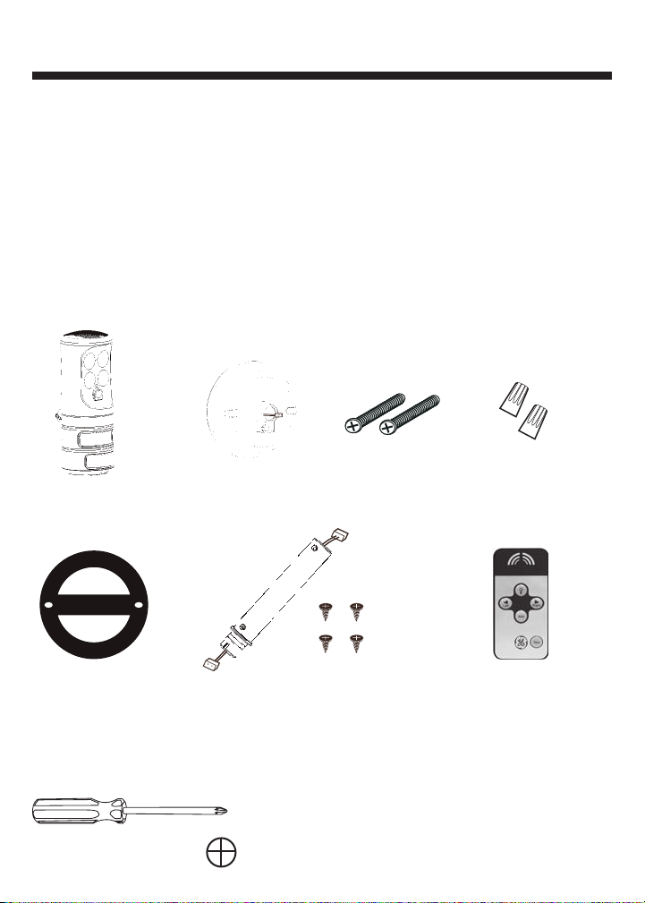
PARTS LIST
Before installing please ensure all the following items are
included in the package:
3
Motion Tracking Light
Gasket
TOOLS NEEDED:
Phillips head screwdriver #2
2 Mounting ScrewsMounting Base 2 Wire Connectors
Horizontal Mount Extension Tube
and Extension Tube Screws (4)
Remote Control
Questions? Problems? Missing Parts?
If you have any questions regarding the installation or operation of the
product, Before returning to Retailer, please contact Technical Support at
1-800-654-8483, option 4, Monday thru Friday 8am - 5pm, Central Standard
Time Zone.
WARNING: Turn power off at circuit breaker or fuse box. Do Not rely
on a wall switch alone to turn off power.
Consult a local licensed electrician or electrical contractor if you are not
sure about the installation. Always install wiring connections in
accordance with local code, ordinances and National Electric Code.
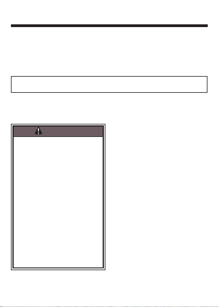
WARNING
Risk of electric shock
- Turn power off before servicing—see
instructions.
- Ensure that no bare wires are exposed
outside the electrical connections.
Risk of injury
- LED light output is strong enough to
injure human eyes. Precautions must
be taken to prevent looking directly at
the LEDs with unaided eyes for more
than a few seconds.
- Some metal parts in the fixture may
have sharp edges. To prevent cuts and
scrapes, wear gloves when handling
the parts.
- Account for small parts and destroy
packing material, as these may be
hazardous to children.
Risk of fire
- Minimum 90º C supply conductors
No serviceable parts
Non-replaceable LEDs
4
INSTALLATION
Select an existing outdoor light fixture, either wall or eave mount for replacement. The fixture must be connected to 120v, 60hz power source.
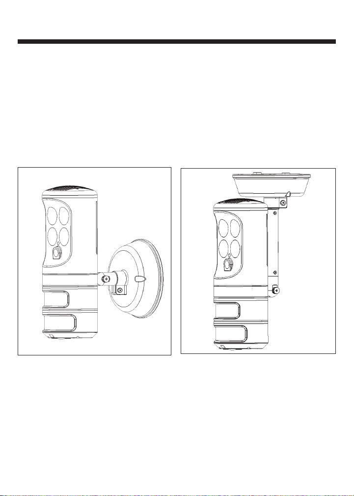
MOUNTING PREPARATION FOR THE LED SPOT LIGHT FIXTURE
For maximum flexibility, the LED Security light can be mounted on a
wall (vertical) or under the eave (horizontal).
Eave MountWall Mount
5
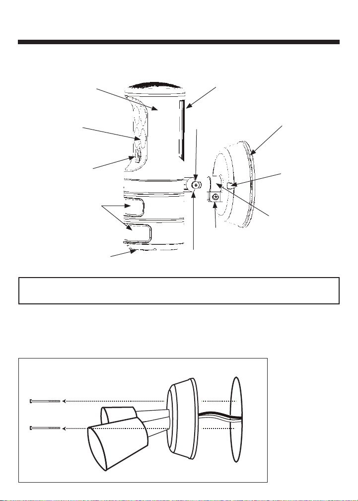
LED Security Spotlight Features
Rotating Light
Housing
6
LED Heat Sink
LED Lights (4)
Decoy Camera and
Red Indicator LED
Dual Motion Sensors
Bottom mount LEDs
and Motion Sensor
Thumb Screw
Collar Screw
Adjustment Knuckle
Mounting Base
Mounting
Holes
Securing Collar
WARNING: Turn power off at circuit breaker or fuse box. Do Not rely
on a wall switch alone to turn off power.
VERTICAL (WALL) MOUNT AND WIRE CONNECTION
1. Remove the existing light fixture and disconnect house wires
(black, white and ground)[See Fig. 1].
Fig. 1
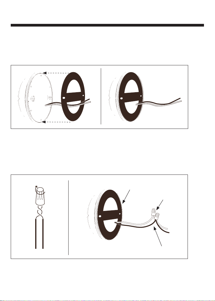
2. Route black and white wires coming from back of mounting base through
the bottom hole of the gasket [See Fig. 2]. Align the two mounting screw
holes on the gasket to the two mounting screw holes on the mounting base
and press the gasket flush to the mounting base.
Fig. 2
3. Locate black and white wires coming from back of mounting base. Strip
wires 3/8” (9.5mm) if not previously stripped. Hold BLACK house wire and
BLACK fixture wire together with ends even. Align any frayed strands or
conductors. Push wires into wire nut and screw Clockwise until two twists
arevisible in the wires [See Fig. 3] . Repeat above procedure for both the
WHITE house wire and the WHITE fixture wire.
Fig. 3
Gasket
White
to White
7
Black to Black
Note: The Motion Tracking Spot Light does not utilize a house ground wire
because of the plastic material of the mounting base. The house ground wire
does not attach to the mounting base. If a house ground wire is present,
position inside junction box.
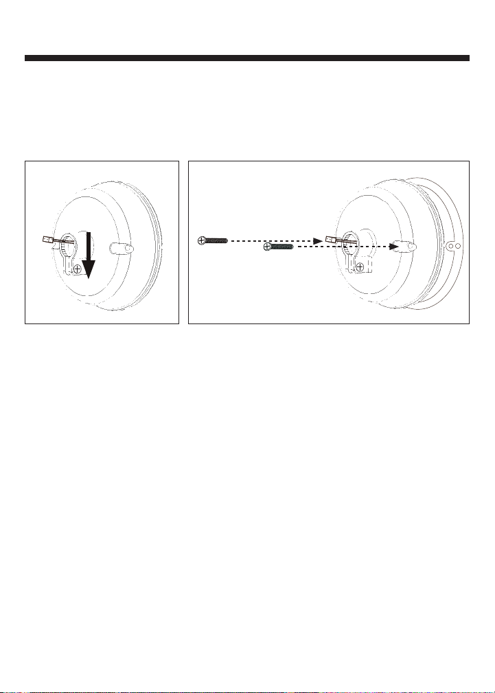
4. If mounting to a wall (in vertical position) ensure the mounting base
is correctly oriented with the collar screw positioned downward
[See Figure 4A].
Fig. 4A
Fig. 4B
Position mounting base and gasket over the junction box. Ensure wires and
wire nuts are positioned inside the junction box. Align holes of mounting
base with mounting holes in junction box. Insert mounting screws as shown
[See Fig. 4B]. Ensure that gasket is evenly positioned around mounting base.
Using screwdriver, screw mounting screws into junction box until mounting
base is snug; do not over-tighten.
8
Note: If a wet location junction box was not used, caulk edge of mounting
base with silicone weather resistant sealant (not included).
5. Plug the wire connector from the base into the wire connector from the
LED Motion Tracking fixture [See Fig. 5A]. Next, insert adjustment knuckle into
mounting base collar opening. Position connectors and wire inside
adjustment knuckle, take care not to pinch the wire. When properly inserted,
adjustment knuckle will snap into place. Tighten collar screw of securing
collar until snug [See Fig. 5B]. Do not over tighten.
 Loading...