

Page 1
Indoor | Outdoor
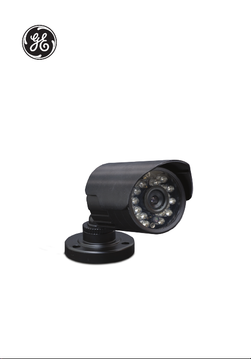
Home Monitoring
Wired
Color Camera
User Manual
For indoor/outdoor use.
www.jascoproducts.com
45244
1-800-654-8483
Page 2

2
Table of Contents
Product Features .................................................................... 3
Package Contents .................................................................. 3
Choosing A Camera Mounting Location ..................... 4
Testing the System ................................................................ 5
Connecting to a TV ................................................................ 6
Connective to a VCR or DVR .............................................. 7
Long Range Night Vision .................................................... 8
Installation ................................................................................. 9
Notes on Cable Installation .............................................13
Specifications .........................................................................14
Warranty ..................................................................................15
FCC Statement .......................................................................16
Page 3

Thank you for purchasing the GE Wired Color Camera.
Please review these instructions carefully before
attempting to operate the unit.
PRODUCT FEATURES
• Weather resistant metal camera casing,
designed for outdoor use
• Black anodized finish prevents rust and
unwanted reflections
• Long Range Night Vision — high-powered LED’s
allow you to see up to 60 ft in the dark
• Multi-axis camera mount allows for installation
at any angle
• Vandal resistant bracket hides cable
• Adjustable sun shield to minimize glare
PACKAGE CONTENTS
Please check and identify all the parts before
proceeding with the installation.
1. Wired Color Camera
2. Mounting hardware for camera (3 screws,
3 plastic anchors, cable clips)
3
Page 4

4
3. AC adapter
4. 60 ft. camera cable (UL approved for in-wall use)
5. 3-Wire TV adapter cable
5. Adjustment wrench
CHOOSING A CAMERA MOUNTING LOCATION
The Wired Color Camera is designed to be mounted
to a wall. It is suitable for indoor or outdoor use. When
choosing a mounting location, please be advised:
• This camera is designed to be reliable for outdoor
use; however its flexible design allows it to be
used indoors as well. It is expecially suited for
viewing large areas in low or no light.
• If using outdoors, take time to first consider
how you will route the cable back to the power
adapter. The cable can be routed out of the back
of the bracket through a wall or ceiling keeping
it hidden and protected, providing a vandal
resistant design. The cable can also be routed
along the surface of a wall or ceiling, through the
slot located on the base of the mounting plate.
• The universal multi-axis bracket allows you to
mount at almost any angle.
• DO NOT position the camera so that it points
Page 5

directly into the sun or any bright light, as this
may cause damage to the camera.
• Avoid positioning the camera so that is viewing
areas where half of the area is in bright sunlight
and the other half is dark, such as the shadow
of a building. All types of cameras have difficulty
“seeing” into areas of such divergent light levels.
• In low light conditions, the camera will
automatically activate its high-powered Infrared
(IR) LED’s and switch the camera to Long Range
Night Vision mode. Long Range Night Vision
viewing distance can be up to 60ft, will be viewed
in B/W.
• The included AC adapter must be positioned
no farther than 8’ from an AC outlet. Do not use
the supplied adapter outside. If you need to
extend the AC adapter cable, 12 ft. extensions
are available by contacting Technical Support at
800-654-8483.
TESTING THE SYSTEM
Before beginning installation, we recommend that
you connect the Wired Color Camera to your TV, VCR
or DVR to help familiarize yourself with the camera
system and choose the best location for installing the
camera.
5
Page 6

6
CONNECTING TO A TV
The Wired Color Camera connects to the video and
audio input jacks on the back of your TV, VCR or DVR.
If you are not using a VCR or DVR, connect the Wired
Color Camera to your TV as shown in the diagram.
To view:
1. Switch on the TV; set the volume to midpoint.
Note: For temporary installation you can connect the camera to
the TV, VCR or DVR without using the 60 ft. extension cable. Simply
connect the 3-Wire adapter cable directly to the end of the 6 ft.
cable coming from the camera.
Power
Video In
TV
Audio In
2. Plug in the AC adapter into the 3-wire adapter cable
and insert the yellow cable into the yellow video jack
and the white cable to the left white audio jack of
the TV.
Page 7

3. Select the AV input assigned to the camera on your
TV by pressing the button labeled AV or VIDEO on
either your TV or TV remote control. You should now
be able to see and hear the output from the camera.
Note: You can extend the cable using the 60 ft. extension cable at
any time to optimally locate the camera (provided the cable length
is sufficient). The camera cable can be extended up to 300 ft. Contact the Technical Support group (1-800-654-8483) for information
reguarding adding extension cables.
CONNECTING TO A VCR or DVR
If you are using a VCR or DVR, connect the Wired
Color Camera Wired Outdoor Color Camera as shown
below:
TV
7
Power
Video
In
Audio
In
VCR
Video
In
Audio
Out
Audio
In
Video
Out
Page 8

8
To view:
1. Switch on the TV and VCR or DVR; Connect the
Wired Color Camera to the VCR or DVR by connecting
the 3-Wire adapter cable directly to the end of the
6 ft. cable coming from the camera. Plug in the AC
adapter to the 3-wire cable and insert the yellow
cable to the video jack and the white cable to the left
white audio jack. You can extend the cable using the
extension cable at any time to optimally locate the
camera (provided the cable length is sufficient).
2. Select the VCR channel on your TV (3 or 4). This
should be the channel or input you normally use to
watch the VCR or DVR.
3. Select the AV input on your VCR or DVR by pressing
the button labeled AV or VIDEO on the VCR/DVR or
on the VCR/DVR’s remote control. You should now be
able to see and hear the output from the camera.
Once your preferred mounting location has been
selected, disconnect the camera cable and turn off
power to the TV, VCR or DVR, then proceed to the
installation section of the manual.
LONG RANGE NIGHT VISION
The Wired Color Camera features Night Vision
Technology. Objects and images can be seen in little
or no light up to 60 ft. The camera uses a special
image sensor that automatically detects available
Page 9

light levels. It turns on/off the high powered InfraRed (IR) LEDs on the front of the camera. These LEDs
provide artificial light that allows the camera to ‘see’
in the dark. Long Range Night Vision will appear as
a Black and White image. When the image sensor
detects enough light, color will return to the images.
For Installation, you will need:
- A Drill
- 3/8" drill bit (if running cable thru wall or ceiling)
- 1/16" drill bit (for drilling screw pilot holes if mounting
into wood or non-brick material)
- 3/16" drill Bit (for drilling holes if using plastic
anchor’s for mounting onto drywall or brick material)
- A Phillips screwdriver
Step 1. Mounting preparation
Once a suitable location for the
camera has been selected and
the cable route has been
determined, you will need to use
the camera’s mounting bracket
as a template to mark holes for
drilling. Mark three holes on the wall for the anchors
or screws as shown. Please take care to mark the
center of the holes.
9
Page 10

10
Step 2. Cable routing -IMPORTANT
(a) If running the cable along the wall surface,
position cable through slot at base of mounting
bracket before installing mounting bracket (see
figure A).
Figure A (Running cable on surface of wall)
Pilot holes for
mounting screws
(b) If the cable needs to be ran through a wall or
ceiling, then an additional hole will need to be
drilled using the 3/8" drill bit. Drill the hole in the
center of the three mounting screw holes (see
figure B). Fit connector and cable through hole
before securing the mounting bracket.
Figure B (Running cable through a wall)
Plastic
anchors
Page 11

11
Step 3. Mounting bracket
(a) If mounting to a stud, wood surface or other non-
brick material, use a 1/8" drill bit to drill pilot holes.
Align holes in mounting bracket to drilled holes,
insert screws and screw in until plate has secure
fit. Do not over tighten screws.
(b) If mounting to drywall or brick material, use
plastic anchors (see Figure C). Using a 3/16" drill
bit (masonry bit, if drilling into brick), drill holes and
insert anchors into drilled holes for snug fit. Align
holes in mounting bracket to drilled holes, insert
screws and screw in until plate has secure fit. Do
not over tighten screws.
(c) Using included adjustment wrench, slightly loosen
the hex head bracket nuts on camera bracket to
position camera’s multi-axis bracket so camera
is pointed toward desired viewing area. Tighten
bracket nuts. Do not over tighten nuts.
Figure C (Mounting bracket using plastic anchors)
Plastic anchors
Page 12

12
(d) Take care to position the camera in the correct
orientation. To ensure the camera image is not
positioned upside down, you
may have to rotate the camera
Proper
Position
housing so the light sensor is
positioned below the lens.
Step 4. Running cable
Run the 60' cable from the
Lens
Light
Sensor
camera’s location to the location
of the TV, VCR or DVR. Use the cable clips provided
to keep the cable in place. (See Notes on Cable
Routing) Take care not to pierce, puncture or cut
the cable when securing.
Step 5. AC Power
Attach the end of the extension cable to the
3-wire adapter cable. Plug in the AC adapter to
the power connector of the 3-wire cable. Insert
the yellow connector into the video jack and
white connector into the audio jack of the TV
monitor or DVR. Plug-in AC adapter to nearest AC
outlet. Adapter must be used in a dry location.
If additional cable length is required, 60 ft.
extension cables are available at select retailers.
The maximum length the cable may be extended
from the camera is 240 ft. For information
regarding the availability of extension cables, you
may contact Technical Support at 1-800-6548483 or visit online at www.jascoproducts.com.
Page 13

13
Step 6. Adjusting Camera View
Adjustments can now be made to the camera
viewing angle. Loosening the hex head bracket nuts
slightly with the hex head wrench (included). Tilt
and rotate the camera head to the desired position.
The camera’s universal multi-axis mount can be
adjusted at different angles for ceiling or wall mount .
Adjustments at these points will allow the camera to
be positioned at virtually any angle. Tighten hex head
nuts when completed.
NOTES ON CABLE INSTALLATION
1. Use care when running the cable from the camera
to the TV, VCR or DVR; when securing the cable, do
not cut, pierce or puncture.
2. Keep the camera cable away from other cables
where possible, in order to reduce the risk of picture
and audio interference.
3. Avoid laying the cable next to any heat sources.
4. If the cable is run along the ground, a protective
covering must be used to prevent the cable from
being damaged, stepped on or becoming a tripping
hazard.
If you have any questions or feel the camera system is
not operating correctly, or you simply need additional
information, please visit our web site
www.jascoproducts.com, or contact our Technical
Support Group 1-800-654-8483.
Page 14

14
SPECIFICATIONS (Subject to change without notice.)
AC/DC Adapter
Power supply operating voltage .......................................................120V 60Hz
Output voltage ......................................................................................................15V DC
Output current .......................................................................................................330mA
Camera
Camera operating voltage ............................................................................15V DC
Current consumption...............................................................220mA maximum
Camera type .....................................................................................Color 1/3” CMOS
Horizontal resolution ..............................................................................496 TV lines
High-Speed Electronic Shutter .....................................................016s to 6.3us
Lens ...........................................................................................6mm, F1.5 Fixed Focus
Video signal output ................................................................1 Vp-p into 75 Ohm
Audio signal output .............................................................1 Vp-p into 10k Ohm
Overall size ...................................................................................................Diameter: 2”
Pre-connected Cable type ..................................................6 conductor cable
Lead Connectors......................................................................6 pin mini-DIN plug
60’ Lead Cable type .................................................................. 6 conductor cable
Connectors .............................................................................6 pin mini-DIN socket
Operating Temperature ..................................-4°F to 104°F (-20°C to 40°C)
Humidity ...................................................................................................Less than 85%
Page 15

WARRANTY
ONE-YEAR LIMITED WARRANTY: Jasco Products Company warrants this
product to be free from manufacturing defects for a period of one year
from the original date of consumer purchase. This warranty is limited
to the repair or replacement of this product only and does not extend
to consequential or incidental damage to other products that may be
used with this unit. This warranty is in lieu of all other warranties express
or implied. Some states do not allow limitations on how long an implied
warranty lasts or permit the exclusion or limitation of incidental or
consequential damages, so the above limitations may not apply to you.
This warranty gives you specific rights, and you may also have other rights
which vary from state to state. If unit should prove defective within the
warranty period, return prepaid with dated proof of purchase to:
Jasco Products Company
10 E. Memorial Road, Oklahoma City, OK 73114
15
Page 16

FCC STATEMENT
This device complies with part 15 of the FCC
rules. Operation is subject to the following
two conditions:
(1) This device may not cause harmful
interference.
WARNING
Risk of fire and shock
• Only use the supplied cUL listed AC to DC adapter.
• The supplied adapter is for indoor use only.
• When securing the cable, do not cut or puncture
• Do not use adapter in wet locations
(2) This device must accept any interference
received, including interference that may
cause undesired operation.
FCC NOTE: The manufacturer is not responsible for any radio or TV interference caused
by unauthorized modifications to this equipment. Such modifications could void the
user’s authority to operate the equipment.
NOTE: This equipment has been tes ted and found to comply with the limit s for a Class B
digital device, pursuan t to Part 15 of the FCC Rules. These limits are designe d to provide
reasonable protec tion against harmful interfere nce in a residential installa tion. This
equipment generat es, uses and can radiate radio frequency energy and, if not installed
and used in accordance with the inst ructions, may cause harmful inter ference to radio
communication s. However, there is no guarantee that interfere nce will not occur in a
particu lar installat ion. If this equipment does cause harmful interferen ce to radio or
television reception, which can be determined by turning the equipme nt off and on, the
user is encouraged to try to correc t the interference by one or more of the following
measures:
- Reorient or relocate the receiving ante nna.
- Increase the separatio n between the equipment and receiver.
- Connect the equipme nt into an outlet on a circuit different from tha t to which the
receiver is connected .
- Consult the dealer or an experience d radio/T V technician
for help.
Made in China
is a trademark of General Electric Company
and is used under license to Jasco Products Company LLC,
10 E. Memorial Road, Oklahoma City, OK 73114
www.jascoproducts.com
45244 rev. 6/01/10
 Loading...