

Page 1
25&$,,,2SHUDWLRQ
0DQXDO
© 1997 GBC Pro-Tech
Do not duplicate without written permission
A
U
S
NOT
E
M
E
E
C
R
N
G
E
E
G
N
R
C
U
'
Y
D
S
T
T
E
OP
R
R
A
M
E
E
R
G
S
U
A
E
N
NOT
C
Y
S
E
T
C
OP
TOP
1
O
PRESSURE
40
20
ADJ
LAMINATOR ROLL CONTROLS
POWER
FAN TABLE
PRO-TECH Engineering Madison,WI 608-246-8844
9
6
12
3
15
0
18
SPEED
MOTOR CONTROLS
BOTTOM
HEAT
1
O
80
100
ROLL
N
E
G
R
U
'
FWD
AUTO
REV
STOP
30
A
R
25
R
E
T
D
20
15
A
U
S
NOT
E
M
E
E
C
R
N
G
E
E
G
N
R
C
U
'
Y
D
S
T
T
E
OP
R
R
A
M
E
E
R
G
S
U
A
E
N
NOT
C
Y
S
E
T
C
OP
N
E
A
R
G
R
E
R
T
U
'
D
by Pro-Tech
DANGER
GEFAHR
HAZARDOUS
VOLTAGE.
o. 5025-PT
To be serviced only
eorder N
R
by trained and
authorized personnel.
Lockout power before
servicing.
s, Inc. 800-748-0241
unication System
m
om
C
azard
1994 H
©
4151 Anderson Road
De Forest, Wisconsin 53532
Part Number 930-402 Rev. A
GBC Pro-Tech
Tel: 608-246-8844
Fax: 608-246-8645
Page 2

ORCA-III Operation Manual
The information in this publication is provided for reference and is believed to be
accurate and complete. GBC Pro-Tech is not liable for errors in this publication or for
incidental or consequential damage in connection with the furnishing or use of the
information in this publication, including, but not limited to, any implied warranty of
fitness or merchantability for any particular use.
GBC Pro-Tech reserves the right to make changes to this publication and to the
products described in it without notice. All specifications and information concerning
products are subject to change without notice.
Reference in this publication to information or products protected by copyright or
patent does not convey any license under the rights of GBC Pro-Tech or others. GBC
Pro-Tech assumes no liability arising from infringements of patents or any other rights
of third parties.
This Manual is Copyrighted © 1997 by GBC Pro-Tech. All rights reserved. The
information contained in this manual is proprietary and may not be reproduced, stored,
transmitted, or transferred, in whole or in part, in any form without the prior and
express written permission of GBC Pro-Tech .
ii
GBC Pro-Tech 1997 October
Page 3
ORCA-III Operation Manual
7DEOH RI &RQWHQWV
6HFWLRQ 6DIHW\
Caution/Warning Label Locations.......................................................................................1-5
6HFWLRQ ,QVWDOODWLRQ
Preinstallation Checklist......................................................................................................2-1
Unpacking............................................................................................................................2-4
Setup...................................................................................................................................2-5
Leveling...............................................................................................................................2-6
Startup.................................................................................................................................2-6
6HFWLRQ 2SHUDWLRQ
Safety ..................................................................................................................................3-1
Operator Controls................................................................................................................3-3
Operator Controls................................................................................................................3-3
Front Control Panel..........................................................................................................3-3
Rear Control Panel...........................................................................................................3-4
Setup................................................................................................................................3-4
Laminator Roll Pressure...................................................................................................3-4
Loading the Film..................................................................................................................3-5
Positioning the Film.............................................................................................................3-5
Heating................................................................................................................................3-6
Cooling ................................................................................................................................3-6
Paper Tips...........................................................................................................................3-6
Process Control Charts .......................................................................................................3-7
Mounting Only .....................................................................................................................3-7
Setup................................................................................................................................3-7
Procedure.........................................................................................................................3-7
Mounting/Laminating...........................................................................................................3-7
Setup................................................................................................................................3-7
Procedure.........................................................................................................................3-7
Encapsulation......................................................................................................................3-8
Setup................................................................................................................................3-8
GBC Pro-Tech 1997 October iii
Page 4

ORCA-III Operation Manual
Procedure.........................................................................................................................3-8
Encapsulation (With Envelope Feed)..................................................................................3-8
Two-Pass Mount and Laminate (Hot and Cold)...................................................................3-8
Setup................................................................................................................................3-8
Procedure, Pass 1............................................................................................................3-8
Procedure, Pass 2............................................................................................................3-8
Cold/Mount Laminate ..........................................................................................................3-9
With Hot Main Rolls: ........................................................................................................3-9
With Cold Main Rolls:.......................................................................................................3-9
Roll to Roll Transfer and Laminate (One Pass)...................................................................3-9
With Hot Main Rolls: ........................................................................................................3-9
Vinyl Transfer ......................................................................................................................3-9
Roll to Roll Transfer.............................................................................................................3-9
With Hot Main Rolls: ........................................................................................................3-9
Roll to Roll Cold Overlamination (Second Pass Main Rolls Hot) ......................................3-10
With Hot Main Rolls: ......................................................................................................3-10
PROCESS CONTROL CHART 3-1...................................................................................3-11
PROCESS CONTROL DIAGRAM 3-1B.............................................................................3-12
PROCESS CONTROL CHART 3-2...................................................................................3-13
PROCESS CONTROL DIAGRAM 3-2B.............................................................................3-14
PROCESS CONTROL CHART 3-3...................................................................................3-15
PROCESS CONTROL DIAGRAM 3-3B.............................................................................3-16
PROCESS CONTROL CHART 3-4...................................................................................3-17
PROCESS CONTROL DIAGRAM 3-4B.............................................................................3-18
PROCESS CONTROL CHART 3-5...................................................................................3-19
PROCESS CONTROL DIAGRAM 3-5B.............................................................................3-20
PROCESS CONTROL CHART 3-6...................................................................................3-21
PROCESS CONTROL DIAGRAM 3-6B.............................................................................3-22
PROCESS CONTROL CHART 3-7...................................................................................3-23
PROCESS CONTROL DIAGRAM 3-7B.............................................................................3-24
PROCESS CONTROL CHART 3-8...................................................................................3-25
PROCESS CONTROL DIAGRAM 3-8B.............................................................................3-26
PROCESS CONTROL CHART 3-9...................................................................................3-27
PROCESS CONTROL DIAGRAM 3-9B.............................................................................3-28
iv
GBC Pro-Tech 1997 October
Page 5
ORCA-III Operation Manual
PROCESS CONTROL CHART 3-10 .................................................................................3-29
PROCESS CONTROL DIAGRAM 3-10B...........................................................................3-30
PROCESS CONTROL CHART 3-11 .................................................................................3-31
PROCESS CONTROL DIAGRAM 3-11B...........................................................................3-32
PROCESS CONTROL CHART 3-12 .................................................................................3-33
PROCESS CONTROL DIAGRAM 3-12B...........................................................................3-34
PROCESS CONTROL CHART 3-13 .................................................................................3-35
PROCESS CONTROL DIAGRAM 3-13B...........................................................................3-36
Laminate Temperature Guide and Helpful Hint Sheet for GBC Pro-Tech Products.........3-37
All Pressure Sensitive Materials.....................................................................................3-37
Lamination......................................................................................................................3-37
Mounting ........................................................................................................................3-37
Vinyl Transfer.................................................................................................................3-37
6HFWLRQ 0DLQWHQDQFH DQG 7URXEOHVKRRWLQJ
Cleaning ....................................................................................................................... .......4-1
Adjusting the Main Roll Nip .................................................................................................4-3
Adjusting the Pull Roll Nip...................................................................................................4-4
Chain Tensioning and Take-Up...........................................................................................4-5
Adjusting the Air Cylinder Rate............................................................................................4-6
Lubrication...........................................................................................................................4-8
Contacting Technical Support .............................................................................................4-8
Schematic Diagram.............................................................................................................4-9
Pneumatic Diagram.............................................................................................................4-2
Output Troubleshooting Guide............................................................................................4-9
6HFWLRQ :DUUDQW\
Limited Warranty .................................................................................................................5-1
Exclusions to the Wa rranty ..............................................................................................5-1
6HFWLRQ 7HFKQLFDO ,QIRUPDWLRQ
Specifications ......................................................................................................................6-1
Illustrated Parts List.............................................................................................................6-2
6HFWLRQ ,QGH[
GBC Pro-Tech 1997 October v
Page 6
ORCA-III Operation Manual Safety
6HFWLRQ 6DIHW\
DO NOT ATTEMPT TO OPERATE YOUR
ORCA-III LAMINATOR UNTIL YOU
HAVE READ THI S S E CT I O N
CAREFULLY!
Your safety, as well as the safety of others, is
important to GBC Pr o- Tech. This section contains
important s afety information.
The following symbols are used t hroughou t this
manua l to indicate warnings and cautions .
DANGER
Indicates an imminently hazardous situation
which, if not avoided, will res ult in death or
serious injury.
WARNING
Indicates a potentially hazardous situation
whic h, if not a voide d , c ould result i n death or
serious injury.
CAUTION
GBC Pro- Tech la minators are powerful machines
that are designed to mount, laminat e and encap sulate.
The forces required t o accomplish thes e tasks can
var y f rom negligible to very large.
The a ir-c ylinder sys tem used to provide downward
pressure on the top roll is capable of producing
forces greater than 1000 pounds (454 kg). This force
is applied to any object pres ent ed in t he op ening
(called the nip) between the two rolls.
Use care in lowering the t op main laminating roll and
know how to r eact qu ic kly in an emergency. The
laminat or roll UP-DOWN s witch is located on t he
instrument panels. This s witch controls t he u p and
down motion of the t op lamina tor roll. B efore
pressing this switch to the DOWN position, ensure
that nothing is in the nip area. If any pr oblem or
danger should occ ur, depr essing any of the
emergency but tons s tops the rolls f rom closing and
ra ises them completely.
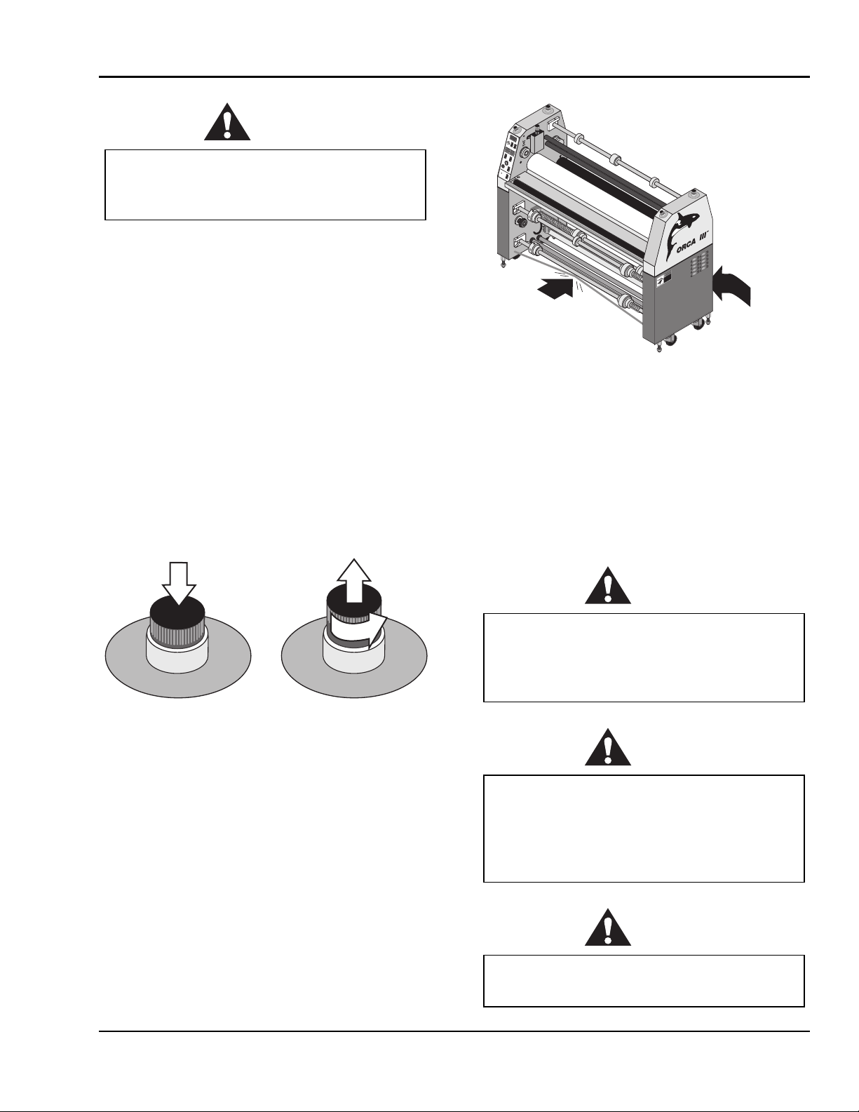
Note
⇒
To quickly stop the machine in the event of an
emergency, press any of the emergency stop buttons
or apply force to either kick cable. This action stops
the machine completely and raises the rolls.
In addition, the laminating rolls of the ORCA-III can
reach temperatures of over 200 °F (100 °C). At these
temperatu res t here is a danger of a sever e b urn if the
rolls ar e t ouched during set- up, operation or
servicing.
Indicates a potentially hazardous situation
whic h, if not a voide d , c ould result i n minor or
moderate injury, or alerts against unsafe
practice s, o r ale r t s against ac tions which co uld
damage the product.
The ORCA-III Laminator has been designed with
saf ety as a primary considerat ion. However , you
must b ecome thoroughly familiar with the controls,
proper oper at ion, proper s ervi ce proced ures, a n d
saf ety featur es of the laminator before using or
servicing the unit.
GBC Pro-Tech 1997 October
An important feature of the laminator is the
photoelectric eye sys tem th at st ops the machine wh en
objects move into the nip area.
In “run” mode (forward or revers e arrow is lit
const antly) forward or r everse butt on must b e pushed
for progress to resume.
In “footswit c h” mode (forward or reverse ar row is
flas hing) rolls stop if photoelect ric eye is b loc ked b ut
resu me a utomatica lly when ob struction is removed
from the p hotoelectric eye pa th.
1-1
Page 7
Safety ORCA-III Operation Manual
A
U
S
NOT
E
M
E
E
C
R
N
G
E
E
G
N
R
C
U
'
Y
D
S
T
T
E
OP
R
R
A
M
E
R
E
S
G
U
A
E
N
NOT
C
Y
E
S
T
C
OP
N
3
0
E
A
R
25
G
R
E
T
R
U
'
D
20
PRO-TECH Engineering Madison,WI 608-246-8844
15
9
WARNING
Do not ever attempt to override the
photoelectric eye system. You could be
crushed or severely burned.
6
FWD
12
3
AUTO
15
0
18
SPEED
REV
MOTOR CONTROLS
STOP
TOP
1
BOTTOM
HEAT
1
O
PRESSURE
O
4
0
2
0
8
0
ADJ
1
00
ROLL
LAMINATOR ROLL CONTROLS
POWER
FAN TABLE
A
U
S
NOT
E
M
E
E
C
R
N
G
E
E
G
N
R
C
U
'
Y
D
S
T
T
E
OP
R
R
A
M
E
E
R
S
G
U
A
E
N
NOT
C
Y
E
S
T
C
OP
N
E
A
R
G
R
E
T
R
U
'
D
The ORCA-III Laminator has a steel cabinet that is
bolted closed to isolate the electric al and d rive system
components for the sa f ety of the op erator. Only a
qualif ied s ervice technician shou ld open these
cabinets.
The la mina tor is equipped with two emergency stop
kick cables located on the b ottom front and rear of
the lamina tor and four emergency stop b utt ons
locat ed on the top of either si de of the laminator. Any
of these, if engaged, stop s the la minator. To continue
operation all four emergency stop butt ons must be in
the up position.
Push any button
to stop the
laminator
A
U
S
NOT
E
C
N
E
G
R
U
'
D
T
E
R
T
OP
R
A
E
M
E
R
G
E
N
C
Y
S
Twist each button
to resume
operation - the
button pops up
A
U
S
NOT
1
/
4
E
C
N
E
G
R
U
'
D
T
E
R
R
E
M
n
r
u
t
Y
S
T
OP
A
E
R
G
E
N
C
by Pro-Tech
DANGER
S
U
GEFAHR
O
D
.
R
E
Emergency
Stop Kick
Cable
A
G
Z
A
A
T
H
L
O
T
V
-P
5
2
0
5
.
o
N
r
e
To be serviced only
rd
o
e
R
by trained and
authorized personnel.
Lockout power before
servicing.
1
4
2
0
8
4
-7
0
0
. 8
c
In
,
s
m
te
s
y
S
n
io
t
a
ic
n
u
m
m
o
C
rd
a
z
a
H
4
9
9
1
©
Emergency
Stop Kick
Cable
Figure 1-2: Using the Emergency Stop Kick
Cables
Despite the safety features built into the ORCA-III
La mi nator , ex tr eme cauti o n must be used when
operating or servic ing the unit. READ THE
FOLLOWING WARNINGS AND CAUT IO NS
BEFORE ATTEMPTING TO OPERATE OR
SERVICE THE O RCA-III L AMINATO R.
WARNING
Never place fingers or arms between the rolls
when they are turning or when the rolls are in
the closed position. You can be crushed or
burned.
Figure 1-1: Using the Emergency Stop Buttons
1-2
WARNING
Do not wear ties, loose fi tting cl othi ng o r
dangling jewelry w hile o pe rat ing o r servicing
the laminator. These items can get caught in
the nip and choke you or you can be crushed
or burned.
WARNING
Always use care in lowering the top laminating
roll. You can be crushed or burned.
GBC Pro-Tech 1997 October
Page 8
ORCA-III Operation Manual Safety
WARNING
Do not operate the laminator near water. You
can be severely shocked, electrocuted or cause
a fire.
DANGER
Remove power from the laminator before
servicing. You can be severely shocked,
electrocuted or cause a fire.
WARNING
Do not use liquid or aerosol cleaners on the
laminator. Do not s pill liquid of any kind on
the laminator. You can be severely shocked,
electrocuted or cause a fire. Use only a damp
cloth for cleaning.
CAUTION
Raise the upper main roll when the laminator
is not in operation. Prolonged contact can
damage the rolls.
CAUTION
Excess pressure can damage the laminating
rolls. Always select the minimum roll pressure
necessary to complete the task.
CAUTION
If silicone adhesiv e c o ntact s the upper or
lower roll, remove it IMMEDIATELY using
80% (o r s tro nger) isopropy l alcohol. It can
harden within an hour and ruin the roll.
WARNING
Exercise care when cleaning the rolls with
80% (o r s tro nger) isopropy l alcohol:
•
Use only in a well ventilated area.
•
Wear rubber gloves.
•
Use only on cool rolls.
Cle aning heated r olls ca n igni te t he fumes .
CAUTION
Use only 80% (o r s tro nger) isopropy l alcohol
or a rubber cement eraser to clean the
laminating rolls. Harsh chemicals like toluene,
acetone or M EK des t r o y the silicone covering
of the rolls.
WARNING
The operating environment must be free of
dust, flammable liquids and vapors. You can
be injured by inhaling chemical vapors. Vapor
build up or stored flammable liquids can cause
a fire. Excessive dust can damage the
laminator.
CAUTION
Do not use a kni fe or other sharp ins trument
during installation or while se r v ic ing t he
laminator. You can cause irreparable damage
to the rolls.
GBC Pro-Tech 1997 October
1-3
Page 9
Safety ORCA-III Operation Manual
WARNING
Do not attempt to move the laminator across
anything other t han a flat, level surface
without trained and qualified riggers. You can
be crushed or seriously injured.
The ORCA-III Laminator is a large and
heavy piece of equipment. It is necessary to
employ LICENSED RI GG E RS ONLY to
move the machine. The laminator is not
designed to be tipped up or sideways in any
way. Such action disturbs the exact alignment
of the rolling parts of the machine and
requires extensive realignment. GBC Pro-
Tech’s warranty does not cover malfunction of
the equipment due to mishandling and/or
tipping.
GBC Pro - Tech bears no responsibility for
personal injury or damage due to moving the
laminator improperly.
WARNING
Do not allow anything to rest on the power
cord. Do not locate the cord where people can
walk on it. You or others can be severely
shocked, electrocuted or cause a fire.
WARNING
Never insert objects of any kind through any
of the slots on the laminator. You can touch
dangerous voltage points or short out parts.
You can be severely shocked, electrocuted or
cause a fire.
ALWAYS USE GOOD SAFETY PRACT IC ES
WHEN OPERATING OR SER VICING THE
LAMINATOR AND KNOW HOW TO REACT
QUICKLY IN AN EMERGENCY.
WARNING
Only a qualified electrician should connect
power to the laminator. You can be severely
shocked, electrocuted or cause a fire if power
is improperly applied.
WARNING
Do not operate the laminator if the power
cord is damaged or frayed. You can be
severely shocked, electrocuted or cause a fire.
Contact a qualified electrician to replace the
cord.
1-4
GBC Pro-Tech 1997 October
Page 10

ORCA-III Operation Manual Safety
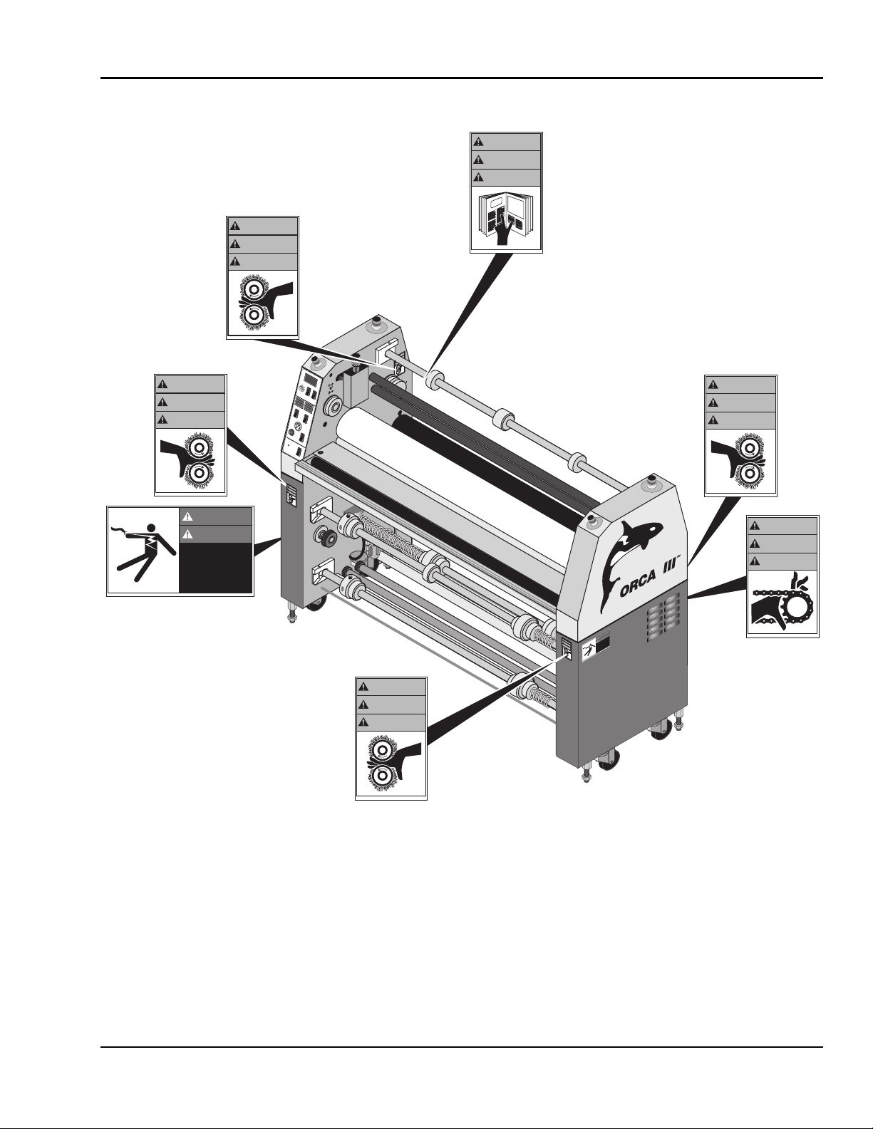
&DXWLRQ:DUQLQJ /DEHO /RFDWLRQV
Posted at various locations on your ORCA-III
Laminator are important safety labels. PAY
CAREFUL ATTENTION TO THESE LABELS AT
ALL TIMES! F i gure 1 - 3 shows the location of ea c h
of t h ese label s.
GBC Pro-Tech 1997 October
1-5
Page 11
Safety ORCA-III Operation Manual
WARNING
ACHTUNG
MISE EN GARDE
WARNING
©1994 HCS, Inc. 800-748-0241 Reorder No.1033R-PT
WARNING
ACHTUNG
MISE EN GARDE
©1994 HCS, Inc. 800-748-0241 Reorder No.1033-PT
DANGER
DANGER
GEFAHR
GEFAHR
HAZARDOUS
HAZARDOUS
VOLTAGE .
VOLTAGE .
To be serviced only
To be serviced only
by trained and
by trained and
authorized personnel.
authorized personnel.
Lockout power before
Lockout power before
servicing.
©1994 Hazard Communication Systems, Inc. 800-748-0241 Reorder No. 5025-PT
©1994 Hazard Communication Systems, Inc. 800-748-0241 Reorder No. 5025-PT
servicing.
(Inside cabinet)
ACHTUNG
MISE EN GARDE
1
O
ADJ
LAMINATOR ROLL CONTROLS
POWER
W
ARNING
ACHTUNG
MISE EN GARDE
©1994 HCS, Inc. 800-748-0241
Reorder No.1033R-PT
TOP
PRESSURE
40
20
FAN TABLE
6
3
0
SPEED
MOTOR CONTROLS
HEAT
80
100
PRO-TECH Engineering Madison,WI 608-246-8844
9
FWD
12
15
18
REV
STOP
BOTTOM
1
O
ROLL
A
U
S
NOT
E
M
E
E
C
R
N
G
E
E
G
N
R
C
U
'
Y
D
S
T
T
E
OP
R
R
A
M
E
E
R
G
S
U
A
E
N
NOT
C
Y
S
E
T
C
OP
N
30
E
A
R
25
G
R
E
R
T
U
'
D
20
15
AUTO
WARNING
ACHTUNG
MISE EN GARDE
T
P
R
3
3
0
1
.
o
N
r
e
d
r
o
e
R
1
4
2
0
-
8
4
7
-
0
0
8
.
c
n
I
,
S
C
H
4
9
9
1
©
©1994 HCS, Inc. 800-748-0241 Reorder No.6001-PT
WARNING
ACHTUNG
MISE EN GARDE
A
U
S
NOT
E
M
E
E
C
R
N
G
E
E
G
N
R
C
U
'
Y
D
S
T
T
E
OP
R
R
A
M
E
E
R
G
S
U
A
E
N
NOT
C
Y
S
E
T
C
OP
N
E
A
R
G
R
E
R
T
U
'
D
©1994 HCS, Inc. 800-748-0241 Reorder No.1033-PT
WARNING
ACHTUNG
MISE EN GARDE
by Pro-Tech
DANGER
WARNING
GEFAHR
ACHTUNG
HAZARDOUS
MISE EN GARDE
VOLTAGE.
To be serviced only
by trained and
authorized personnel.
Lockout power before
servicing.
©
1
9
9
4
H
C
S
, In
c
. 8
0
0
-7
4
8
-0
2
4
1
R
e
o
r
d
e
r N
o
.1
0
3
3
R
-P
T
©1994 Hazard Communication Systems, Inc. 800-748-0241 Reorder No. 5025-PT
©1994 HCS, Inc. 800-748-0241 Reorder No. 1012-PT
1-6
WARNING
ACHTUNG
MISE EN GARDE
©1994 HCS, Inc. 800-748-0241 Reorder No.1033R-PT
Figure 1-3: Locations of Safety Labels
GBC Pro-Tech 1997 October
Page 12

ORCA-III Operation Manual Installation
6HFWLRQ ,QVWDOODWLRQ
GBC Pro- Tech is c ommitted to a program of ongoing
product improvement. As a result, we are providing
these instructions so that you c an insu re that you r
new ORCA-III Laminator is properly and securely
unpacked, moved and insta lled.
Before an ORCA-III Laminator can be installed there
are a few r equirements t hat mus t be met. Ma k e
certain that each of the requirements listed in the
following pr eins tallation c hecklis t are met befor e
beginning installation.
CAUTION
Do not locate the laminator where air is
blowing directly on the machine. The air flow
can cool the rolls unevenly and result in poor
❒ Have you c ontac ted a certified electricia n to bot h
wire the laminator and ensure that an adequate
power supply, having the appropriate capacity,
overcurr ent pr otection, and saf ety lockout s is
available?
The laminator requires 220 to 240 VAC, 50/60
Hz, 55 A. Or, in Europe only, 3-N phase, 32 A
per phase.
CAUTION
quality output.
Failure to follow the preinstallation checklist
can result in damage to the laminator.
3UHLQVWDOODWLRQ &KHFNOLVW
❒ Are door ways and hallways wide enough f or t he
laminator to be moved to the installation site?
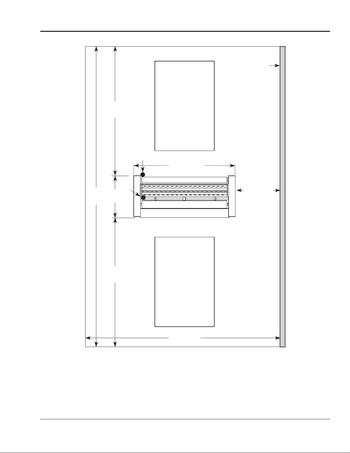
❒ Is there a mple room for the laminator?
A work area mus t be est ablis hed t hat allows for
operation in b oth the front and the r ear of the
machine and p rovides s pac e for effic ient mater ial
flow. Figure 2-1 shows a typical machine area
layout.
❒ Is t he envir onment app ropria te for the laminator?
The la mina tor requires a c lean, du st and vapor
free environment to oper ate properly. I t must not
be located where there is a ir blowing directly on
the machi n e.
WARNING
USA - For singl e pha se 3 wire, tie L 1, L2, an d
L3 t ogether.
Europe - For 3-N phase, L1, L2, and L3 are each
separate phases.
WARNING
Do not operate the laminator if the power
cord is damaged or frayed. You can be
severely shocked, electrocuted or cause a fire.
Contact a qualified electrician to replace the
cord.
WARNING
Do not allow anything to rest on the power
cord. Do not locate the cord where people can
walk on it. You or others can be severely
shocked, electrocuted or cause a fire.
The operating environment must be free of
dust, flammable liquids and vapors. You can
be injured by inhaling chemical vapors. Vapor
build up or stored flammable liquids can cause
a fire. Excessive dust can damage the
laminator.
GBC Pro-Tech 1997 October
2-1
Page 13
Installation ORCA-III Operation Manual
❒ Is there an appropriate filtered air supply
available?
The lamin ator requires filtered air at 2 cubic feet
per minute (cfm), 50 liters/minute at a pressure
of 100 pounds per square inch (psi) (700 kPa).
The air supply must be clean (free of dirt) and
dry. Moisture caus es c orrosion and particles
block pneu ma tic cont rols. Eit her pr oblem can
cause the laminator to malfunction.
It is the cus tomer's responsibilit y to pr ovide
appropriate filters and water traps for the air
hose before the a i r is r o ut ed to the laminato r.
Pro-Tech suggests that the best approach to the
air requirement is to p rovide a dedicated sma ll
compressor for the laminator. A standard lightduty ½ to ¾ horse power (1 kW) electric air
compressor with 1.5 to 2.5 cfm output with a 5
gallon (2 0 liter ) storage tank is appropriate.
CAUTION
The air supply to the laminator must be clean
and dry or the machine will be damaged.
2-2
GBC Pro-Tech 1997 October
Page 14
ORCA-III Operation Manual Installation
20'
(609 cm)
8'8"
(264 cm)
Supply
2'8"
(81 cm)
Electrical
Supply
Air
4' x 6'
(122 cm x 182 cm)
Work Table
on Wheels
Table Height
35-3/4"
(90.5-91.5 cm)
82" (208 cm)
Rear
Front
Wall
3' (91 cm)
8'8"
(264 cm)
4' x 6'
(122 cm x 182 cm)
Work Table
on Wheels
Table Height
35-3/4"
(90.5-91.5 cm)
13' (396 cm)
Figure 2-1: Laminator Space Requirements
GBC Pro-Tech 1997 October 2-3
Page 15
Installation ORCA-III Operation Manual
8QSDFNLQJ
A
U
S
NOT
E
M
E
E
C
R
N
G
E
E
G
N
R
C
U
'
Y
D
S
T
T
E
OP
R
R
A
E
M
E
R
S
G
U
⇒ NOTE
ALL SHIPMENTS ARE EX- WORKS. At our dock
title passes to the buyer. Please review your
insurance coverage prior to shipment, as you are
responsible for all subsequent freight charges and
risks. Before signing the Bill of Lading you should
be sure to inspect the crate and/or pallet for signs of
damage or missing items; if applicable, make a note
of this on the Bill of Lading.
WARNING
A
E
N
NOT
C
Y
S
E
T
C
OP
N
3
0
E
A
R
25
G
R
E
R
T
'
U
D
20
15
P
R
O
-TE
C
4
H
E
n
gineering M
adiso
9
6
n,W
I 608-246
FWD
12
3
-8844
AUTO
15
0
18
SPEED
REV
MOTOR CONTROLS
1
STOP
T
O
O
P
HEAT
1
B
O
T
O
T
O
M
PRESSURE
4
0
2
0
ADJ
8
0
1
0
0
ROLL
LAMINATOR ROLL CONTROLS
POWER
FAN
3
1
5
Install
Screws
A
U
S
NOT
E
M
E
E
C
R
N
G
E
E
G
N
R
C
U
'
Y
D
S
T
T
E
OP
R
R
A
E
M
E
R
S
G
U
A
E
N
NOT
C
Y
S
E
T
C
OP
N
E
A
R
G
R
E
R
T
'
U
D
by Pro-Tech
DANGER
GEFAHR
HAZARDOUS
T
VOLTAGE.
-P
5
2
. 50
o
N
er
rd
To be serviced only
o
e
R
by trained and
authorized personnel.
Lockout power before
servicing.
1
4
02
8
4
-7
0
0
. 8
c
In
s,
m
te
s
y
S
n
tio
a
ic
n
u
m
m
o
C
d
ar
z
a
H
4
9
9
1
©
2
The unpacking process requires at least two
people. You can be severely injured or
crushed.
Tools required:
• Phillips head screwdriver
7
/8" open end wrench or adju stable wrench
•
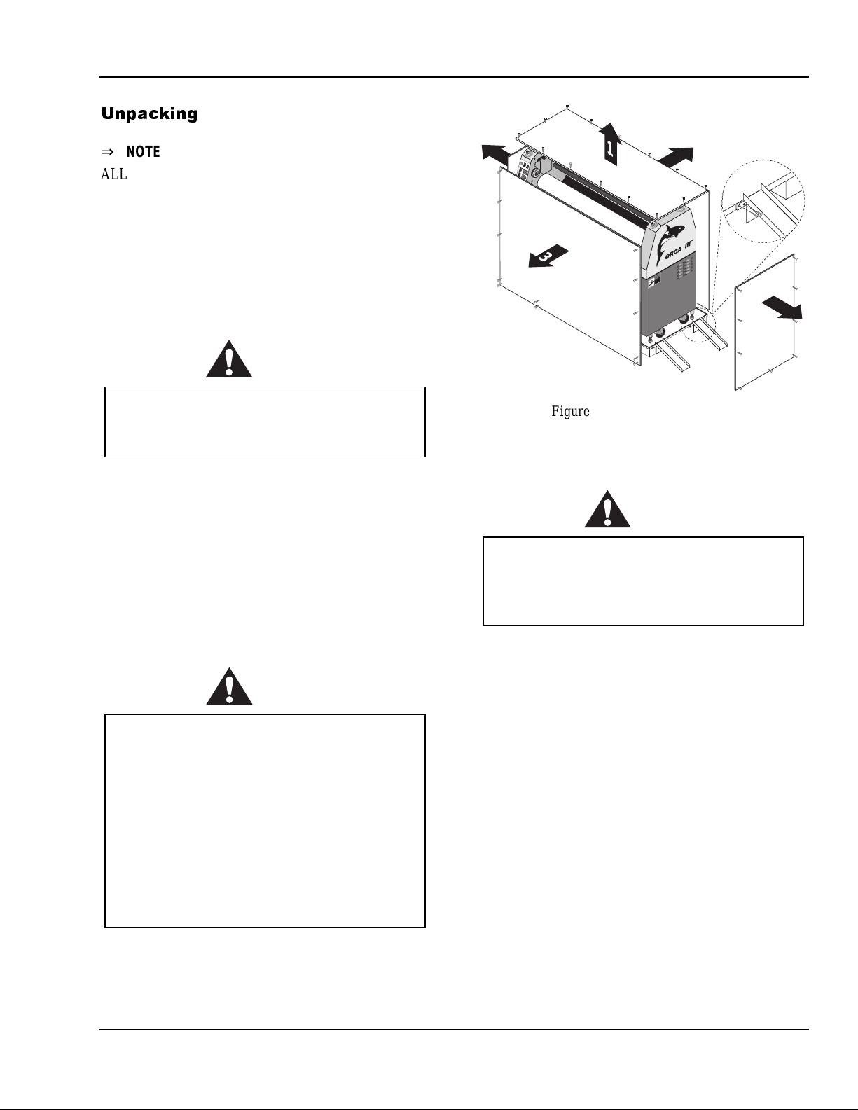
To uncrate the laminator:
1. Remove the top of the crate and then the sides in
the order shown in Figure 2-2 .
CAUTION
Do not allow the top to fall into the crate. It
can damage the laminator.
Do not put packing screws on the floor. They
can cause problems when trying to roll the
machine into position.
A second person must support the side labeled
5 in Figure 3-4. It can fall and damage the
laminator.
Figure 2-2: Removing the Crate
2. Carefully unwrap the shrink wrap f rom around
the laminator.
CAUTION
Do not use a kni fe or other sharp ins trument
during installation or while se r v ic ing t he
laminator. You can cause irreparable damage
to the rolls.
3. Ca refully remove any a c c es sories pac ked wit h
the laminator. The accessory pack should
contain:
1 Set, hex wrenches
5
/16" T-handle wrench
1
1 Slitting knife
1 Manual
1 Set, spare fuses
1 Air line qu ic k- c ouple connector, f emale
100% white cotton terry rags
4. Have t he laminator r olled off the skid and plac ed
on the floor by licensed r iggers. The ramps
included with the laminator can be secured to the
edge of the crate b ottom us ing the screws left
over from the crate dis assembly (see Figure 2 - 2).
2-4
GBC Pro-Tech 1997 October
Page 16
ORCA-III Operation Manual Installation
Before machines leave our loading dock, they are
WARNING
Do not attempt to move the laminator across
anything other t han a flat, level surface
without trained and qualified riggers. You can
be crushed or seriously injured.
pre-treated with a VCI protective film to provide
total corrosion protection. This protective film is
wrapped around the machine and completely sealed.
In addition, moisture absorbing silicone desiccite
packs are packed inside the crate and machine
cabinets.
The ORCA-III Laminator is a large and
heavy piece of equipment. It is necessary to
employ LICENSED RI GG E RS ONLY to
move the machine. The laminator is not
designed to be tipped up or sideways in any
way. Such action disturbs the exact alignment
of the rolling parts of the machine and
requires extensive realignment. GBC Pro-
Tech’s warranty does not cover malfunction of
the equipment due to mishandling and/or
tipping.
GBC Pro - Tech bears no responsibility for
personal injury or damage due to moving the
laminator improperly.
5. Remove any pl astic strapping and packing paper
taped to the
roll
s.
CAUTION
Do not use a kni fe or other sharp ins trument
during installation or while se r v ic ing t he
laminator. You can cause irreparable damage
to the rolls.
6. Remove all packing mat erials to a saf e dis tance
from the laminator.
⇒
A NOTE ABOUT RECYCLING
The crate components can be reused for shipping
the machine again, or can be disassembled and the
wood and screws recycled. The shrink wrap is not
recyclable, h o wever, s o i t mu s t be d i s ca r ded .
Prior to start up of the machine, you must remove
the desiccite packs from each cabinet and discard.
DO NOT operate the machine with the desiccite
packs inside the cabinets
7. Level the lamina tor u sing the procedure lat er in
this s ection.
6HWXS
Once the ORCA-III Laminator has been unpacked
and moved into final pos ition check ea c h of the
following items.
Tools required:
1
•
/8" hex wrench
•
Adjust able wrench
Setup Procedure
1. Insp ect the la minator for any obviou s shipping
damage.
2. Open t he left and r ight side cabinet c overs wit h
3. Insp ect all the bolts and tighten a ny that were
4. Have a cert if ied electricia n wire the lamina tor
5. Set th e n i p. (See Maintenance for t h e pr o cedure.)
6. Verify that the infra red sensors ar e not blocked.
5
/32" hex wrench by removing the four scr ews
the
holding each cover in plac e.
loosened duri ng shipping.
directly to a power source.
⇒
NOTE
A word about international shipments: As these are
heavy pieces of equipment, GBC Pro-Tech takes
every precaution to ensure that our laminators are
properly crated to the highest standards.
GBC Pro-Tech 1997 October
WARNING
NEVER BLOCK T H E I NFRARED
SENSO RS! The rolls can overheat and cause
a fire or seriously damage the laminator.
2-5
Page 17
Installation ORCA-III Operation Manual
7. Adjust the air cylinder rate. (See Section 4:
Maintenance and Troubleshooting for the
procedure.)
8. Replace both cabinet covers.
/HYHOLQJ
Tools required:
• Adjustable wrench
• Carpenter's level
To lev e l t he laminator:
1. Ra ise each end, remove the cas tors and ins tall a
leveling pad a nd stu d onto each of the foot
brackets at the four bottom corners of the
laminator. T hread t hird nut on st ud ab ove f oot
bracket.
WARNING
Do not lift the wheels more than 3/4" (2 cm.)
above the floor. The leveling pads can become
unstable. You can be crushed.
2. Thread s tud int o 4 leveling pads loc k down with
nut. T hread second nut onto stud.
3. Place a carpenter's level front to rear across the
two lower tie ba rs at one end of the machine .
4. Level this end of the machine fr ont to r ear,
ra ising or lowering the leveling pads by a djusting
the middle nuts on the foot b olts.
5. Move the level to t he other end of t he machine
and level front to rear.
6WDUWXS
The first time the laminator is started and every time
it is s erviced you should use the following checklist to
confirm t hat the unit is op erating properly and that all
saf ety mechanisms ar e functioning.
Startup Checklist
Star t the la minator and go t hrough the following
checklist.
❒ Are the emergency stop but tons working?
Push down on one of the emergency s top b utt ons.
The laminator should stop. Pull up on the but ton
and push t he reset but ton on the lower back of
the lamina tor. The laminator shou ld resu me
operation. Always c hec k all four bu ttons.
WARNING
Never operate the laminator unless both of the
emergency stop buttons are functioning
properly. You can be crushed or burned.
❒ Is t he p hotoelectr i c eye system working?
With t he la minator ru nning and the r olls in the
“up” position, place an object approximately the
size of you r hand just in f ront of the nip on b oth
the fr ont and back of the lamina tor to confirm
that the photoelectric eye system is func tioning.
The
the nip. The lamina tor should r es ume operation if
the machine is in “footswitch” mode. I f the
machine is in “ run” mode, it shou ld be necessa ry
to push the FORWARD or REVE RSE button
to resume roll motion.
s shou ld stop . Move t he ob ject away fr om
roll
6. Place the level direct ly on one of the tie ba rs and
level the machine side to si de.
7. Recheck t he front to rear level condition to ins ure
that it has not c hanged. I f it has, repeat the
leveling procedure.
8. When all the measurements indicate that the
machine is level, tighten down the top nuts on t he
foot b rac kets t o loc k the pads in their current
position.
2-6
WARNING
Never operate the laminator unless the
photoelectric eye system is functioning
properly. You can be crushed or burned.
GBC Pro-Tech 1997 October
Page 18

ORCA-III Operation Manual Installation
❒ Are the emergency stop kic k c ables working?
With t he laminator r unning, s tep on or kic k the
front emergency stop kick cable. All power
should b e removed from the machine. The rolls
should s top t urning and rise. P ush t he reset
but ton. Restar t the heaters , fa ns, and roll mot ion.
Lower the rolls then repeat the test for the back
emergency stop kick cable.
WARNING
Never operate the laminator unless both of the
emergency stop kick cables are functioning
properly. You can be crushed or burned.
❒ Is t he motor func tioning?
Test the motor at variou s speeds ra nging f rom
0-15. At 0 the
Run the motor in both forwa rd and reverse.
s shou ld stop turning.
roll
❒ Are the hea ters working ?
Verify that the top heater controller heats the top
roll a nd the bottom heater c ontroller heat s the
bottom roll.
Once you ha ve c omplet ed the startup c hecklist you
can safely run a test sample.
GBC Pro-Tech 1997 October
2-7
Page 19

Installation ORCA-III Operation Manual
Blank Page.
2-8
GBC Pro-Tech 1997 October
Page 20
ORCA-III Operation Manual Operation
6HFWLRQ 2SHUDWLRQ
6DIHW\
The ORCA-III Laminator has been designed with
saf ety as a primary considerat ion. However , you
must b ecome thoroughly familiar with the controls,
proper oper at ion, proper s ervi ce proced ures, a n d
saf ety featur es of the laminator before using or
servicing the unit.
GBC Pro- Tech la minators a re power ful mac hines
that are designed to mount, laminat e and encap sulate.
The forces required t o accomplish thes e tasks can
var y f rom negligible to very large.
The a ir-c ylinder sys tem used to provide downward
pressure on the top roll is capable of producing
forces greater than 1000 pounds (454 kg). This force
is applied to any object pres ent ed in t he op ening
(called the nip) between the two rolls.
Use care in lowering the top laminat ing roll a nd know
how to r eact qu ic kly in an emergency. The lamina tor
roll UP-DOWN swit c h is located on the inst rument
panels . This switc h c ontrols the up and down motion
of the top laminator roll. Before turning this switch to
the DOWN position, ens ure t hat nothing is in t he nip
area.
In addition, the laminating rolls of the ORCA-III can
reach temperatures of over 200 °F (100 °C). At these
temperatu res t here is a danger of a sever e b urn if the
rolls ar e t ouched during set- up, operation or
servicing.
The ORCA-III Laminator has a steel cabinet that is
bolted closed to isolate the electric al and d rive system
components for the sa f ety of the op erator. Only a
qualif ied s ervice technician shou ld open these
cabinets.
The la mina tor is equipped with fou r emergency stop
buttons located on the top of either side of the
laminator. Any of t hes e, if engaged, stop s the
laminator. To c ontinue oper ation all four emergency
stop buttons must be in the up position.
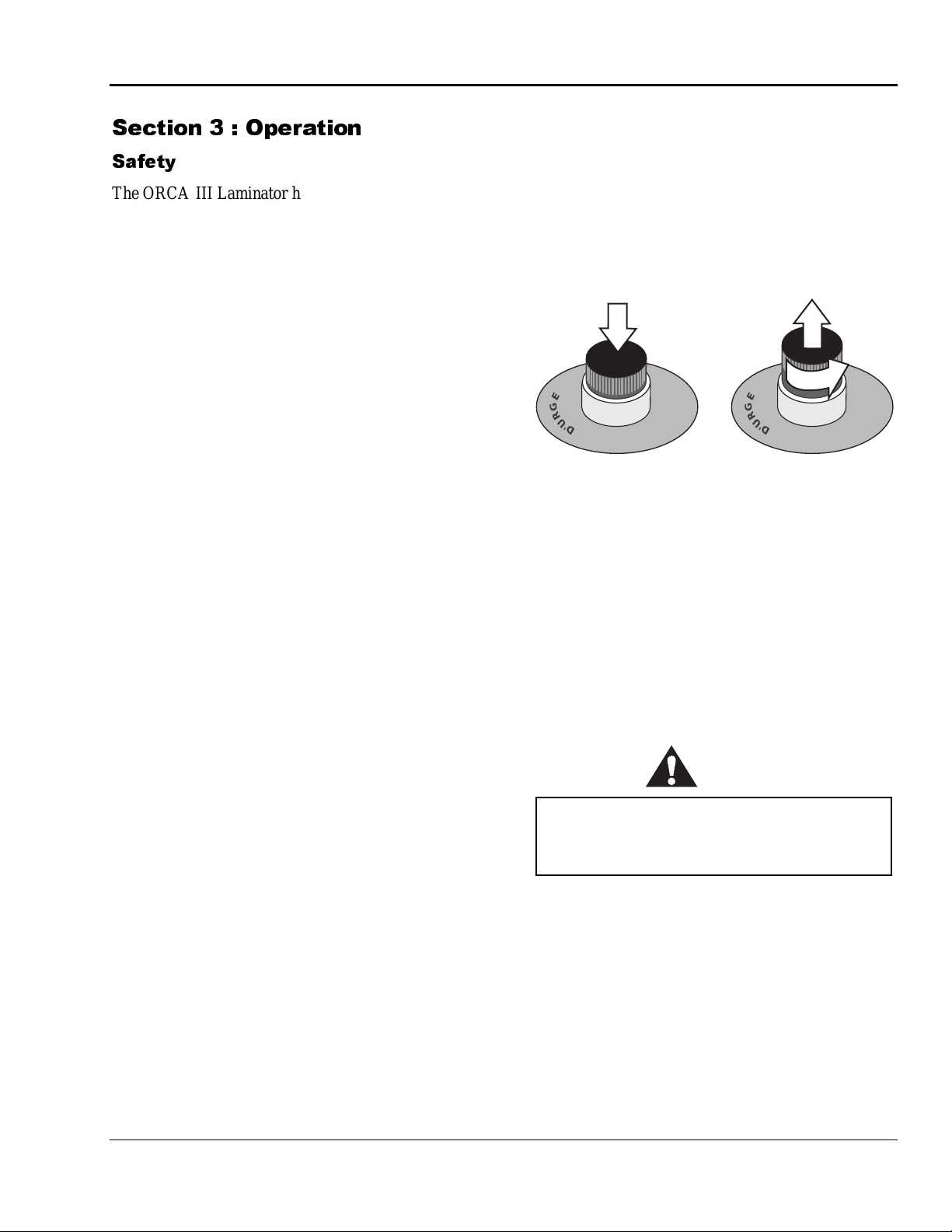
Push any button
to stop the
laminator
A
U
S
NOT
E
C
N
E
G
R
U
'
D
T
E
R
E
M
E
R
G
E
N
C
Y
S
T
OP
R
A
Figure 3-1: Using the Emergency Stop Buttons
Twist each button
to resume
operation - the
button pops up
A
U
S
NOT
1
/
4
E
C
N
E
G
R
U
'
D
T
E
R
R
E
M
n
r
u
t
Y
S
T
OP
A
E
R
G
E
N
C
The ORCA-III is equipped with a photoelectric eye
system that stops the machine when objects move into
the ni p a rea.
In “run” mode (forward or revers e arrow is lit
const antly) forward or r everse butt on must b e pushed
for progress to resume.
In “footswit c h” mode (forward or reverse ar row is
flas hing) rolls stop if photoelect ric eye is b loc ked b ut
resu me a utomatica lly when ob struction is removed
from the p hotoelectric eye pa th.
WARNING
Do not ever attempt to override the
photoelectric eye system. You could be
crushed or severely burned.
In addition to the safety features built into the
ORCA-III Laminator, extreme caution must be used
when opera ting or servicing the unit.
GBC Pro-Tech 1997 October
3-1
Page 21
Operation ORCA-III Operation Manual
In addition, the ORCA-III is equipped with two
Emergency S top Ki c k Cables located at t he lower
front and b ack of the laminator. Either of these, if
stepped on or kicked, st ops the laminat or. To r es tart,
pus h the res et button and reacti vate t he heater s, f ans,
roll motion, and r oll positi on c ontrols .
A
U
S
NOT
E
M
E
E
C
R
N
G
E
E
G
N
R
C
U
'
Y
D
S
T
T
E
OP
R
R
A
M
E
R
E
S
G
U
A
E
N
NOT
C
Y
E
S
T
C
OP
N
3
0
E
A
R
25
G
R
E
T
R
U
'
D
20
PRO-TECH Engineering Madison,WI 608-246-8844
15
9
6
FWD
12
3
AUTO
15
0
18
SPEED
REV
MOTOR CONTROLS
STOP
TOP
1
BOTTOM
HEAT
1
O
PRESSURE
O
4
0
2
0
80
ADJ
1
00
ROLL
LAMINATOR ROLL CONTROLS
POWER
FAN TABLE
A
U
S
NOT
E
M
E
E
C
R
N
G
E
E
G
N
R
C
U
'
Y
D
S
T
T
E
OP
R
R
A
M
E
E
R
S
G
U
A
E
N
NOT
C
Y
E
S
T
C
OP
N
E
A
R
G
R
E
T
R
U
'
D
by Pro-Tech
DANGER
S
U
GEFAHR
O
D
.
R
E
Emergency
Stop Kick
Cable
A
G
Z
A
A
T
H
L
O
T
V
-P
5
2
0
. 5
o
N
r
e
d
To be serviced only
r
o
e
R
by trained and
authorized personnel.
Lockout power before
servicing.
1
4
2
-0
8
4
-7
0
0
. 8
c
, In
s
m
te
s
y
S
n
tio
a
ic
n
u
m
m
o
C
d
r
a
z
a
H
4
9
9
1
©
Emergency
Stop Kick
Cable
Figure 3-4: Emergency Stop Kick Cables
3-2
GBC Pro-Tech 1997 October
Page 22
ORCA-III Operation Manual Operation
2SHUDWRU &RQWUROV
The operator controls for the ORCA-III Laminator
ar e loc ated on t he front and r ear of the unit, to t he
right of the operator posit i on. T he names and
functions of these controls are as follows:
2SHUDWRU &RQWUROV
The operator controls for the ORCA-III Laminator
ar e loc ated on t he front and r ear of the unit, to t he
right of the operator posit i on. T he names and
functions of these controls are as follows:
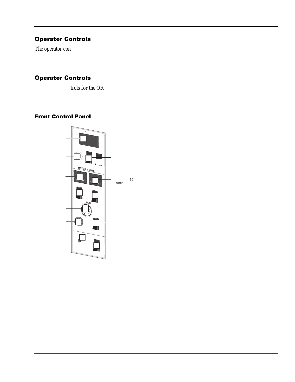
)URQW &RQWURO 3DQHO
PRO-TECH Engineering Madison,WI 608-246-8844
Speed Display
Speed Adjust
Upper Heater
Controller
Upper
Heater
ON/OFF
Main Roll Air
Pressure Gauge
Main Roll Air
Pressure
Adjustment
Power
Light
1
9
FWD
6
3
2
0
18
SPEED
MOTOR CONTROLS
3
TOP
1
4
O
ADJ
6
LAMINATOR ROLL CONTROLS
POWER
7
12
15
13
REV
HEAT
PRESSURE
40
20
5
80
100
11
BOTTOM
1
10
O
FAN TABLE
AUTO
12
STOP
ROLL
9
8
Motor REV/REW
Motor Control
Switch
Lower Heater
Controller
Lower
Heater
ON/OFF
Main Roll Up/Down
Switch
Fan/Vacuum
Table ON/OFF
4. UPPER ROLL HEAT O N/O FF - Turns the
heater c ontroller for the top laminati ng roll on or
off.
5. MAIN ROLL AIR PRES S URE G AUG E -
Displays the air pr es sur e p ushing t he main
laminating roll down.
6. MAIN ROLL AIR PRES S URE CO NT RO L -
Varies the air pressure fed to the cylinders that
drive the t op lamina ting r oll down.
7. POWER LIGHT - Indicates when the main
power is b eing applied t o the machine.
8. FAN/VACUUM TABLE ON/OFF - Turns t he
vacu um ta ble on or off.
9. MAIN ROLL UP/DOW N - Sets the main roll
to the u p (loa d) or down ( operate) p osition.
10. LOWER HEAT ON/OFF - Turns th e h eater
contr oller in the bottom lamina ting roll on or off.
11. LOWER HEATER CONTROLLER -
Pr ovides a readou t of t he t emperature of the
bottom laminating roll and the set-point for the
desired temperature. The upper heater must be on
for the lower hea ter t o function.
12. FOOTS W IT CH / CO NT I NUO US RUN -
Changes control of t he mac hine drive from t he
foots witch to continuou s ru n.
13. MOT IO N CO NT RO L FORWARD/STOP
REVERSE - Controls t he direction of the drive
system - forward, stop, or revers e.
Figure 3-1: Front Control Panel
1. SPEED DISPLAY - Provides digit al readout of
the machi n e speed and tot al throug h put in ei ther
metric or st andard unit s.
2. SPEED ADJUSTMENT - Adjusts the speed of
th e machin e from z e ro to maximum a s the c ontr ol
is tu rned clockwis e.
3. UPPER HEATER CONTROLLER - Provides
a readout of the temperature of the upper
laminating roll and the set-point for the desired
temperature.
GBC Pro-Tech 1997 October
3-3
Page 23
Operation ORCA-III Operation Manual
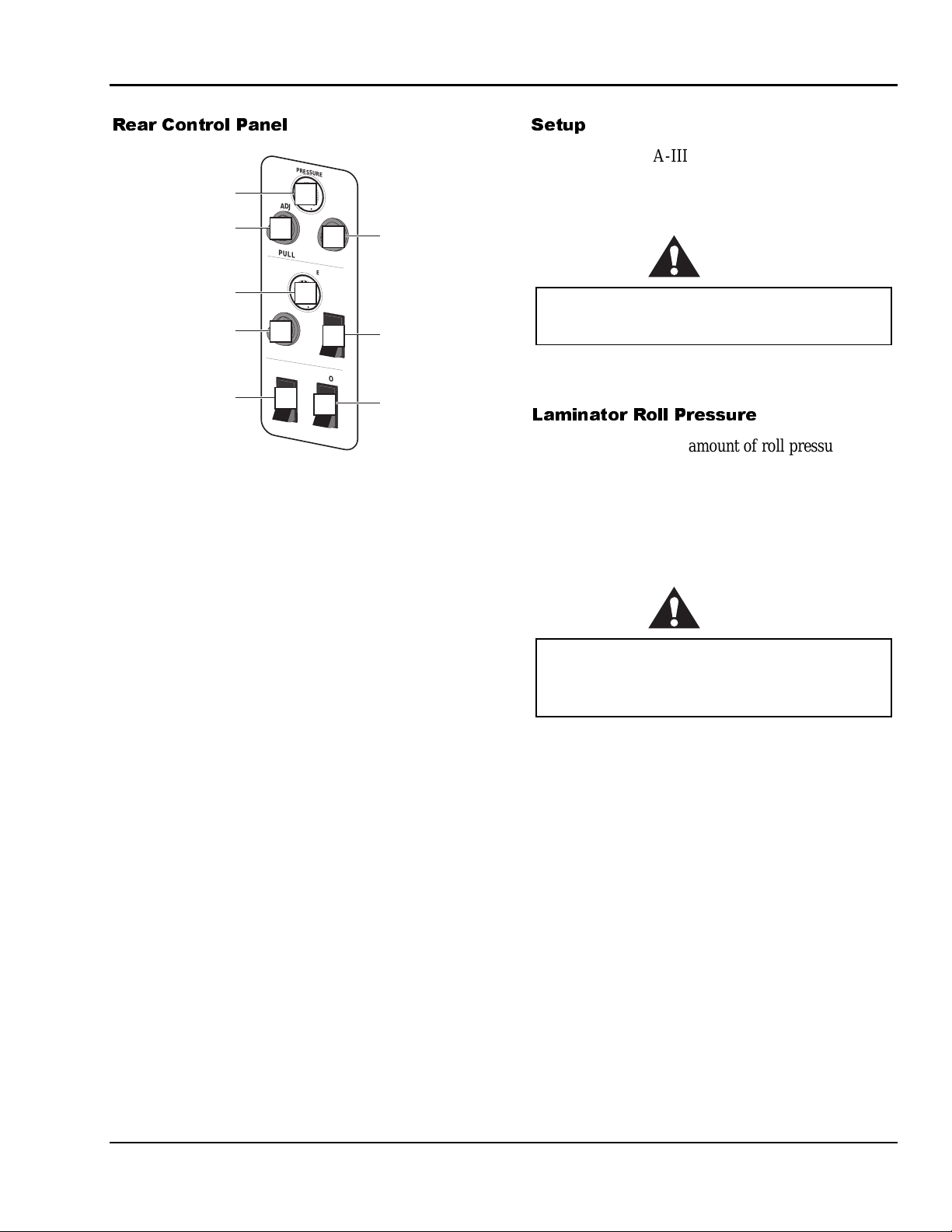
5HDU &RQWURO 3DQHO
PRESSURE
40
20
Pull Roll Clutch Air
Pressure Gauge
Pull Roll Clutch
Air Pressure
Adjustment
Pull Roll Air
Pressure Gauge
Pull Roll Air
Pressure
Adjustment
Cooling Fans
ON/OFF
80
1
100
ADJ
2
PULL ROLL CLUTCH
PRESSURE
40
20
80
3
100
ROLL
ADJ
4
PULL ROLL CONTROLS
COOLING FANS
AUTO
5
6
STOP
8
7
Pull Roll
Clutch
ON/OFF
Pull Roll
Up/Down
Switch
Motor Control
Switch
Figure 3-2: Rear Control Panel
1. PULL ROLL CLUTCH PRESSURE
GAUGE - M easures and displays t he air
pres sur e driving the pull roll clutch, which sets
web tension.
6HWXS
Setup of the ORCA-III Laminator is quick and
straightfor ward when instruct ions are followed
exactly.
CAUTION
Always use the same shim settings on the left
and right side of the laminator.
To adj ust t h e n i p pl eas e see Section 4: Maintenance
and Troubleshooting.
/DPLQDWRU 5ROO 3UHVVXUH
Use only the minimum amount of roll pressure
needed to accomplis h the task. While higher pres sur e
can ma ke t he adhesive bond f aster, exces s pr essure
can damage the rolls. Wrinkles and bubbles have
cau ses that gener ally cannot be c ured by app l ying
more pressure.
2. PULL ROLL CLUTCH AIR PRESSURE
ADJUSTMENT - Adjusts the clutch pressure
from z e ro to maximum a s the control is turned
clockwise.
3. PULL ROLL AIR PRES S URE G AUG E -
Meas ures and disp lays the air pres sur e p ushing
the pull roll down.
4. PULL ROLL AIR PRES S URE
ADJUSTMENT- Varies the air pressure fed to
the cylinders that drive t he pull roll down.
5. COOLING FANS ON/OFF- Tu rns the cooling
fans on or of f .
6. FOOTSWITCH / CO NT I NUO US RUN -
Changes control of t he mac hine drive from t he
foots witch to continuou s ru n.
7. PULL ROLL UP/DOWN - Sets the pull roll to
the up ( load) or down (operate) position.
8. PULL ROLL CLUTCH ON/OFF- Tur ns t he
pull roll clut c h on or off.
CAUTION
Excess pressure can damage the laminating
rolls. Minimum laminator roll pressure is
consistent with good results.
A typical roll pressure for soft substrates such as
Foamcore or Orca-Board is between 20 to 30 pounds
per square inch (PSI) or 140 to 205 kPa.
The r ange of typ ic al values for hard subst rates is 25
to 50 PSI or 170 to 345 kPa.
3-4
GBC Pro-Tech 1997 October
Page 24
ORCA-III Operation Manual Operation
/RDGLQJ WKH )LOP
Film is loa ded on t he appropriate unwinds. Loading
and a ligning the film ar e dis c ussed later in this
section. For ap plications s uch as encap sula tion, f ilm
is fed from both t he top a nd bott om feed unwinds .
The process of loading and aligning film is t he s ame
for both the top and the bottom unwinds. There are
two import ant p oints t o remember when loading film:
1. The a dhesive side of t he film mus t be or ient ed
away ( on the outside) fr om the laminating roll.
Otherwise it will immediately bond to the roll,
creating a major c lean-up pr oject.
Films ha ve a shiny side and a du ll side. The dull
side is t he one with the adhesi ve. The du ll side
should ALWAYS face outward from the
laminating roll.
CAUTION
Always mount the film so that the adhesive
side faces outward from the laminating roll.
This prevents hours of roll cleaning.
2. Th e film must be centered on t h e unwind for best
performance. This is vital when two films are fed
together . If the two films are not aligned, f eed
problems, wrinkles a nd other assorted trou bles
will occur .
3RVLWLRQLQJ WKH )LOP
The following procedur e is app licable t o all the feed
unwinds.
Tools required:
5
/16" T-handle wrench
•
• Tape measure
To position the film:
1. Open t he top unwind by removing the p in and
swinging the a rm out.
2. Position the film chuck with the brake on the left
side of the arm. Make sure that the brake piston
is fully retracted (pu shed in).
3. Load t he film.
4. Center the film on the u nwind arm b y measuring
the distance form the ends of the film to the sides
of the machine using a tape measure.
5. Lock down t he c huck on the right side using the
5
/16" T-handle wrench supplied with your
laminator. Mount a rubber O-ring on the left side
of the film, followed by a film chuck. Be sure
that the collar only touches , bu t does not tighten,
the O-ring.
6. Ti g h ten t h e screw on the brake chuck.
7. Recheck the cent ering of the film roll with the
tape measure. Readjust if necessary.
8. Return the arm to its locked position and reinsert
the locking pin.
CAUTION
Carefully align the two films being fed into the
nip. If not, y o u will o bt ain poo r r e s ults .
GBC Pro-Tech 1997 October
3-5
Page 25
Operation ORCA-III Operation Manual
+HDWLQJ
Use the following instructions when heating one or
both of the laminating rolls. The pr oc edure is t he
same for the top and bottom heaters.
1. Set the heater switch to ON.
2. Adjust the t emper at ur e cont roller for the desired
opera ting temperatur e usi n g the temperatu re
controller push b u ttons.
3. For the Syrlec type controller, use the up and
down arrows to adjust the set point. Hold down
the required arrow until the correct set point is
acheived.
For the CAL3200, it is necessary to press the
star button at the same time as the up or down
arrow to adjust the set point temperature.
4. When heating the rolls, keep t h e top rol l d ow n
and t urning at a modera te speed t o prevent
uneven heating.
5. It will t ake ap prox ima tely 25 minutes for the
laminating roll(s) to reac h op erating temperatu re.
When the pres et operating tempera tu re has been
reac hed, the mac hine is ready to use.
3DSHU 7LSV
1. Always c ut t he lea ding edge of a print s traight so
it ca n be fed perp endicular to t he laminating roll.
2. If you ar e laminat ing very thin p aper s, you
should consider utilizing the ORCA III's envelope
feed. This pa tented techniqu e is the best c hoic e
for the output from electrostatic printers that
have signif i c ant water cont ent or for paper s with
excessive stretch.
6. The ORCA-III can be used for cold mounting
and la mina ting while maintaining the temperat ure
of the main la minating rolls by using the ou tput
rolls as a lamina tor ( by feeding prints from the
rear) f or a quick change-over b et ween hot and
cold laminating.
&RROLQJ
The following is the fastest way to cool down the
machine.
1. Set th e h eater switches to OFF.
2. Position the two rear air tubes so that they are
tilted to direct air flow at the rolls.
3. Set the Laminator Roll Control to the DOWN
position.
4. Set the Forward/Reverse switch to the
FORWARD posit on.
5. Set the speed control to 5 fpm (150 cpm).
6. Let t he machine run until the lamina ting rolls
return to room temperature.
3-6
GBC Pro-Tech 1997 October
Page 26
ORCA-III Operation Manual Operation
3URFHVV&RQWURO&KDUWV
Process control charts allow you to record the way
you thread film through the machine's rolls and idlers
(called webbing) and the control settings for each
product and process. Process control charts are an
excellent tool for training new operators. They
provide a "road map" for correct machine setup and
operation.
This section contains a blank process control chart
and diagram for the ORCA-III as well as completed
charts for the basic operations of the laminator.
GBC Pro-Tech laminators respond in a very accurate
and repeatable manner. The charts provide a way to
set up each time, every time for repeatable
performance by assuring that all controls are set to
optimum.
The process control charts should be kept in this
manual or in a book close to the laminator. Use the
machine to encapsulate the popular charts so they can
withstand food and coffee spills and so they are
always available for ready reference.
⇒
NOTE
When trying new products and processes, remember
that GBC Pro-Tech's customer service
representatives are only a phone call away.In North
America, please call 1-800-236-8843.
The completed process control charts included in this
section are based on Orca-Film, Orca-Board and
typical prints.
0RXQWLQJ2QO\
6HWXS
1. See process charts 3-1, 3-2 and diagram 3-2b.
2. Shims: Set to the thickness of the material being
used for mounting.
3. Upper Laminator Roll Pressure: 40 P SI (275
kPa).
3URFHGXUH
1. Lay the print on the board. Using a tack iron,
tack the leading edge of the print down onto the
board so it is held in place.
2. Put a piece of con tact/release paper over the
print. Otherwise, adhesive will be applied to the
laminating roll, which can cause damage and the
ink from electrostatic prints will be deposited on
the roll.
3. Feed the print/Orca-Board package through the
nip.
0RXQWLQJ/DPLQDWLQJ
The following procedure is for one-step mounting and
heat-activated laminating using mounting board with
one adhesive side (such as Orca-Board).
6HWXS
1. See process chart 3-3 and diagram 3-3b.
2. Mount the film and web as shown in diagram
3-3b.
1
3. Shims: Set the two front shim dials to
than board thickness.
4. Laminator Roll Pressure: 40 PSI (275 kPa).
5. Speed: 3 fpm (90 cpm).
6. Upper Laminator Roll Heat: 230 °F (110 °C).
7. Cooling: Off
8. Film Tension: Minimum amount needed to have
the film lay smooth, about half way up the roll,
on the upper main roll. Generally one to two
turns on the unwind brake.
3URFHGXUH
Feed the Orca-Board dull (adhesive) side up with the
print positioned as desired. A tack iron can be used to
hold the leading edge of the print in place.
/32" less
4. Speed: 3 fpm (90 cpm).
5. Upper Laminator Roll Heat: 230°F (110 °C).
GBC Pro-Tech 1997 October
3-7
Page 27
Operation ORCA-III Operation Manual
(QFDSVXODWLRQ
6HWXS
1. See process chart 3-4 and diagram 3-4b.
2. Shims: None.
3. Front Laminat ing Roll Pressure: 80 PSI
(550 kPa).
4. Back P ull Roll Clu tch Pressure: On, 8 0 PS I
(550 kPa).
5. Pull Roll: Down, Pressu re - 80 PSI ( 550 kPa).
6. Speed: 5-7 fpm (150-210 cpm).
7. Upper Laminator Roll Heat: 220-230 °F
(104-110 °C).
8. Lower Laminator Roll Heat: 220-230 °F
(104-110 °C).
9. Cooling: Optional
10. Use of the r ear wind-up roll for the fi n i shed
mater ial is op tional. It is a good p rocedure for
long runs.
6HWXS
1. See process charts 3-5, 3-6, 3-7, and 3-8 and
diagrams 3-5b, 3-6b, 3-7b, and 3-8b for film
mounting instructions and ma c hine adjustments.
2. Ensure that the mounting film from the bottom
side has the sticky (adhesive) side riding up
ar ound the outside of t he b ottom la mina ting r oll.
3URFHGXUH 3DVV
1. Run the print t hrough to apply adhesive and
laminate.
2. Trim to slightly larger t han the desired finished
size.
3URFHGXUH 3DVV
1. Prepare to p ut t he p rint through a s econd time to
mount the print to the substrate - anything from
wood, t o Masinote, to Gator foam. Start by
setting the shims to the appropriate spacing for
the material used.
2. Trim the board to the size of the print.
3URFHGXUH
Feed the work into the nip with the leading edge tight
and entering the nip evenly from side to s ide. For thin
pap er fr om electrost atic print ers in roll form it is best
to fold over the leading edge approx imately 6 inches
to cr eate a squa re leading edge.
(QFDSVXODWLRQ :LWK (QYHORSH
)HHG
The us e of th e en v el o pe feed featu re greatly
simplifies the input of lar ge ha nd- fed prints. The
proc edure is identical to that f or regu lar
encapsulation ( see above), h ow ev er, the mach i n e
setup is diff erent as shown in proc es s chart 2-5 and
diagram 2-5B
7ZR3DVV 0RXQW DQG /DPLQDWH +RW
DQG &ROG
There ar e severa l ap proa ches to the moun t/ l aminat e
task. I t ca n be accomplished with either hot or cold
laminate film on the top. Also, the second pass f or
mounting can be done by f eeding from either the fr ont
or back of the laminator.
3. Align the wor k to the boar d and ensu re an ex act
fit. Place weights on the center of t he p rint to
make sure tha t it does not move relat i ve t o the
board during t he next st eps.
4. Ra ise one end of the print and peel ba c k
approx i mat ely two inches of the li n er t o expo se
the adhesive that was applied to the print in the
first pass . Fold it under .
5. Lay t h e pr i n t b ack d ow n even ly a nd ext remely
flat. From t he c ent er outward, tac k the expos ed
adhesive to the substrate.
6. Position the pi ece so that the end with the liner
peeled ba ck is fa cing the nip. Insert the first one
inch of the board into the nip. Very carefully
wrap the print back and over the top laminating
rol l . Be sure t h ere ar e no wrink l es in the nip a rea.
Car eful l y peel of f th e l i n er as the b o ard
progress es through the la minator .
7. Trim the p i ece to the f i n i shed size.
3-8
GBC Pro-Tech 1997 October
Page 28

ORCA-III Operation Manual Operation
&ROG0RXQW /DPLQDWH
:LWK +RW 0DLQ 5ROOV
1. See process chart 3-8 and diagram 3-8b for film
mounting instructions and machine adjustments.
2. Move the feed table to the rear of the laminator.
3. Ra ise the main roll ( hot).
The blades on both the infeed and outfeed
slitters are razor sharp. You can cut yourself
9LQ\O 7UDQVIHU
WARNING
severely.
4. Reverse the motor.
5. Web a c c ording to drawing.
6. Set the nip height and tack the lea ding edge for
the second pass . Run thr ough as the liner is being
pulled off.
:LWK &ROG 0DLQ 5ROOV
1. See process chart 3-9 and diagram 3-9b for film
mounting instructions and machine adjustments.
2. Use the machine as a cold laminator with the
main rolls not heat ed.
5ROO WR 5ROO 7UDQVIHU DQG /DPLQDWH
2QH 3DVV
:LWK +RW 0DLQ 5ROOV
1. See process chart 3-10 and diagram 3-10b for
film mounting inst ructions and machine
adjustments.
2. Web the vinyl over the bottom roll and hold with
the pull r olls.
3. It is useful to have a leader on the paper so it can
be webbed t hrough and taped t o the rewind
befor e s tarti ng.
4. Lower the main roll, start the motor, and begin
the tr ansfer proc ess . Ta pe th e finished pro d uct to
the rewind and add t he laminat ion by raising the
pull roll. Web the laminate around the upper pull
roll. Be sure it is smooth on the roll, t hen lower
the roll.
5. Add infeed a n d o ut feed sl itter s a s needed.
1. See process chart 3-11 and diagram 3-11b for
film mounting inst ructions and machine
adjustments.
2. Web the vinyl u p ar ound the bot tom main roll
and over to the pu ll roll. Make s ure the material
is webbed straight and lower t he pull roll to hold
the vinyl.
3. Place both table idlers in the slots on the table
bracket s. Web the paper through a s shown in
diagram 2-11b.
4. Oft en, when paper is not on a c ore, hand tension
must b e applied t o the paper in order t o ma intain
transf er qua lity unt il the end of the trans f erred
image.
5ROO WR 5ROO 7UDQVIHU
:LWK +RW 0DLQ 5ROOV
1. See process chart 3-12 and diagram 3-12b for
film mounting inst ructions and machine
adjustments.
2. Web the vinyl u p ar ound the bot tom main roll
and over to the pull roll. Lower the pull roll t o
hold the vinyl.
3. Web the paper up to the main roll. Lower the
main roll to start the transfer process.
4. Tape t he vinyl ont o the lower rewind and p eel off
the paper. Wind it on the upper rewind.
5. La mina tion can be done in a s econd pass, if
required. See cha rt 2- 13.
GBC Pro-Tech 1997 October
3-9
Page 29

Operation ORCA-III Operation Manual
5ROO WR 5ROO &ROG 2YHUODPLQDWLRQ
6HFRQG 3DVV 0DLQ 5ROOV +RW
:LWK +RW 0DLQ 5ROOV
1. See process chart 3-12 and diagram 3-13b for
film mounting inst ructions and machine
adjustments.
2. Install the brake adapter on the rear rewind.
3. Bring the vinyl up over the bot tom lamination
roll a nd throu gh the main rolls.
4. Tape the overlaminate release liner to the upper
rewind.
5. Web the overlaminate material around the upper
pull roll and lower it to begin over l amination.
3-10
GBC Pro-Tech 1997 October
Page 30

ORCA-III Operation Manual Operation
352&(66 &21752/ &+$57
Product:__________________Process:_________________________Date: _____________
Material Top:___________________________Material Bottom:________________________
Other Material: ______________________________________________________________
FRONT CONTROL SETTINGS
Speed (Ft/min): Reverse/Forward:
Roll Up/Down: Shim Dial:
Roll Pressure: Top Temp. Set:
Top Heater On /Off: Bottom Temp. Set:
Bottom Heater On/Off:
REAR CONTROL SETTINGS
Pull Clutch On/Off: Pull Roll Up/Down:
Pull Clut ch Pressur e: Pull Roll Pressure:
Shim Dial: Cooling:
See Chart 3-1B for Webbing Outline
Special Instructions: __________________________________________________________
__________________________________________________________________________
__________________________________________________________________________
__________________________________________________________________________
GBC Pro-Tech 1997 October
3-11
Page 31

Operation ORCA-III Operation Manual
352&(66 &21752/ ',$*5$0 %
IDENTIFICATION DI AGRAM
(I) Removable Idler
(F) Fixed Idler
(U) Unwind Shaft
(R) Rewind
(M) Main Roll
(P) Pull Roll
(C) Cooling Tube
(S) Slitter Idler
Small Table
Infeed Slitter
S
R
I
I
F
F
M
I I I
M
U
R
Outfeed Slitter
C
P
I
P
C
I
Large Table
R
U
U
S
F
F
R
U
U
Outfeed Slitter
3-12
GBC Pro-Tech 1997 October
Page 32

ORCA-III Operation Manual Operation
352&(66&21752/&+$57
Product:__________________Process:_1-Pass Mounting_________Date:_______________
Material Top:___________________________Material Bottom:_3/16 inch Orca-Board_____
Other Material:______________________________________________________________
FRONT CONTROL SETTINGS
Speed (Ft/min): 3 (90 cm/min) Reverse/Forward: Forward
Roll Up/Down: Down Shim Dial: 3/16 (.48 cm)
Roll Pressure (psi): 40 Top Temp. Set: 230 °F, 110 °C
Top Heater On/Off: On Bottom Temp. Set: 32 °F, 0 °C
Bottom Heater On/Off: On
REAR CONTROL SETTINGS
Pull Clutch On/Off: -- Pull Roll Up/Down: Up
Pull Clutch Pressure (psi): -- Pull Roll Pressure (psi): --
Shim Dial: -- Cooling: No
See Chart 3-2B for Webbing Outline
Special Instructions:__________________________________________________________
__________________________________________________________________________
__________________________________________________________________________
__________________________________________________________________________
GBC Pro-Tech 1997 October
3-13
Page 33

Operation ORCA-III Operation Manual
352&(66 &21752/ ',$*5$0 %
ONE PASS MOUNT (HEAT ACTIVATED ADHESIVE)
Use release
liner if print is
heat sensitive
Hot
Dial Nip
Height
Print
Orca-Board
Hot or
Cold
3-14
GBC Pro-Tech 1997 October
Page 34

ORCA-III Operation Manual Operation
352&(66&21752/&+$57
Product:_Orca-Board________Process:_One Pass Mount and Laminate__Date:__________
Material Top:__3 Mil Gloss______________Material Bottom:_3/16 inch Orca-Board________
Other Material:______________________________________________________________
FRONT CONTROL SETTINGS
Speed (Ft/min): 3 (90 cm/min) Reverse/Forward: Forward
Roll Up/Down: Down Shim Dial: 3/16 (.48 cm)
Roll Pressure (psi): 40 Top Temp. Set: 230 °F, 110 °C
Top Heater On/Off: On Bottom Temp. Set: 32 °F, 0 °C
Bottom Heater On/Off: On
REAR CONTROL SETTINGS
Pull Clutch On/Off: -- Pull Roll Up/Down: Up
Pull Clutch Pressure (psi): -- Pull Roll Pressure (psi): --
Shim Dial: -- Cooling: No
See Chart 3-3B for Webbing Outline
Special Instructions:__________________________________________________________
__________________________________________________________________________
__________________________________________________________________________
__________________________________________________________________________
GBC Pro-Tech 1997 October
3-15
Page 35

Operation ORCA-III Operation Manual
352&(66 &21752/ ',$*5$0 %
ONE PASS MOUNT AND LAMINATE
Over-
laminate
Hot
Print
Orca-Board
Dial Nip
Height
Hot or
Cold
3-16
GBC Pro-Tech 1997 October
Page 36

ORCA-III Operation Manual Operation
352&(66 &21752/ &+$57
Product:___________________Process:_Encapsulation______________Date: ___________
Material Top:__3 Mil Gloss______________Material Bottom:_3 Mil Gloss___ _____________
Other Material: ______________________________________________________________
FRONT CONTROL SETTINGS
Speed (Ft/min): 3-5 (90-152 cm/min) Reverse/Forward: Forward
Roll Up/Down: Down Shim Dial: 0
Roll Pressure (psi): 80 Top Temp. Set: 220 °F, 104 °C
Top Heater On/Off: On Bottom Temp. Set: 220 °F, 104 °C
Bottom Heater On/Off: On
REAR CONTROL SETTINGS
Pull Clutch On/Off: On Pull Roll Up/Down: Down
Pull Clut ch Pressur e (psi): 80 Pull Roll Pressure (psi): 80
Shim Dial: 0 Cooling: On
See Chart 3-4B for Webbing Outline
Special Instructions: __________________________________________________________
__________________________________________________________________________
__________________________________________________________________________
__________________________________________________________________________
GBC Pro-Tech 1997 October
3-17
Page 37

Operation ORCA-III Operation Manual
352&(66 &21752/ ',$*5$0 %
ENCAPSULATION
10 Mil Film
Laminate
Web Film Underneath
This Idler When Using
DETAIL
10 Mil Film (See Detail)
Optional Outfeed
Slitter
Optional
Infeed Slitter
Paper
Optional
Laminate
Hot
Hot
Laminate
Large Table
Optional
Outfeed Slitter
Optional
Rewind
Optional
Laminate
3-18
GBC Pro-Tech 1997 October
Page 38

ORCA-III Operation Manual Operation
352&(66&21752/&+$57
Product:___________________Process:_Encapsulation (Envelope Feed) Date:___________
Material Top:__3 Mil Gloss______________Material Bottom:_3 Mil Gloss___ _____________
Other Material:______________________________________________________________
FRONT CONTROL SETTINGS
Speed (Ft/min): 2-3 (90-122 cm/min) Reverse/Forward: Forward
Roll Up/Down: Down Shim Dial: 0
Roll Pressure (psi): 80 Top Temp. Set: 230 °F, 104 °C
Top Heater On/Off: On Bottom Temp. Set: 230 °F, 104 °C
Bottom Heater On/Off: On
REAR CONTROL SETTINGS
Pull Clutch On/Off: On Pull Roll Up/Down: Down
Pull Clutch Pressure ( psi) : 80 Pull Roll Pressure ( psi): 80
Shim Dial: 0 Cooling: --
See Chart 3-5B for Webbing Outline
Special Instructions:__________________________________________________________
__________________________________________________________________________
__________________________________________________________________________
__________________________________________________________________________
GBC Pro-Tech 1997 October
3-19
Page 39

Operation ORCA-III Operation Manual
352&(66 &21752/ ',$*5$0 %
ENCAPSULATION (ENVELOPE FEED)
Laminate
Print
Optional
Laminate
Hot
Hot
Laminate
Optional
Outfeed Slitter
Optional
Rewind
Optional
Laminate
3-20
GBC Pro-Tech 1997 October
Page 40

ORCA-III Operation Manual Operation
352&(66&21752/&+$57
Product:___________________Process:_Two Pass Mount & Laminate (1st Pass) Date:____
Material Top:__3 Mil Gloss______________Material Bottom:_ Pressure Sensitive Film ___ __
Other Material:______________________________________________________________
FRONT CONTROL SETTINGS
Speed (Ft/min): 3-7 (90-213 cm/min) Reverse/Forward: Forward
Roll Up/Down: Down Shim Dial: 0
Roll Pressure (psi): 80 Top Temp. Set: 220 °F, 104 °C
Top Heater On/Off: On Bottom Temp. Set: 32 °F, 0 °C
Bottom Heater On/Off: On
REAR CONTROL SETTINGS
Pull Clutch On/Off: On Pull Roll Up/Down: Down
Pull Clutch Pressure ( psi) : 80 Pull Roll Pressure ( psi): 80
Shim Dial: 3/16 (.48 cm) Cooling: --
See Chart 3-6B for Webbing Outline
Special Instructions:__________________________________________________________
__________________________________________________________________________
__________________________________________________________________________
GBC Pro-Tech 1997 October
3-21
Page 41

Operation ORCA-III Operation Manual
352&(66 &21752/ ',$*5$0 %
TWO PASS MOUNT AND L AMINATE (FIRST PASS)
Laminate
Optional Outfeed
Trim Rewind
Optional
Outfeed
Trim
Paper Sheet
Feed Hand
Wind on Core
(Tip! - Keep
Leading Edge
Straight-
Parallel to Roll)
Hot
Cold
Optional Paper
on Core
Optional Infeed
Trim Rewind
Optional
Mount
Adhesive
Mount
Adhesive
Optional
Mount
Adhesive
Optional
Outfeed Trim
Optional
Rewind of
Finished
Product
3-22
GBC Pro-Tech 1997 October
Page 42

ORCA-III Operation Manual Operation
352&(66 &21752/ &+$57
Product:___________________Process:_Two Pass Mount & Laminate (2nd Pass) Date: ____
Material Top:__ ______________Material Bottom:_ 3/16 Foamcore ___ _____________
Other Material: ______________________________________________________________
FRONT CONTROL SETTINGS
Speed (Ft/min): 0-7 (0-213 cm/min) Reverse/Forward: Reverse
Roll Up/Down: Up Shim Dial: 3/16
Roll Pressure (psi): -- Top Te mp. Set: --
Top Heater On/Off: On/Off Bottom Temp. Set: --
Bottom Heater On/Off: Off
REAR CONTROL SETTINGS
Pull Clutch On/Off: On Pull Roll Up/Down: Down
Pull Clutch Pressure (psi): 80 Pull Roll Pressure (psi): 20-50
Shim Dial: 3/16 (.48 cm) Cooling: --
See Chart 3-7B for Webbing Outline
Special Instructions: __________________________________________________________
__________________________________________________________________________
__________________________________________________________________________
GBC Pro-Tech 1997 October
3-23
Page 43

Operation ORCA-III Operation Manual
352&(66 &21752/ ',$*5$0 %
TWO PASS MOUNT AND L AMINATE (SECOND PASS)
Can Use Main
Rolls If Cold
If Hot
Dial Nip
Height
Running
Positions
Release Liner
Tack Lead-In
Edge to Board
Starting
Positions
Release Liner
Orca-Board
Shim Dial
3-24
GBC Pro-Tech 1997 October
Page 44

ORCA-III Operation Manual Operation
352&(66 &21752/ &+$57
Product:___________________Process:_Cold Mount/Laminate Date: ______________
Material Top:_1 Mil Gloss________________Material Bottom:_Promount___ _____________
Other Material: ______________________________________________________________
FRONT CONTROL SETTINGS
Speed (Ft/min): 0-14 (0-430 cm/min) Reverse/Forward: Reverse
Roll Up/Down: Up Sh im Dial: 0
Roll Pressure (psi): -- Top Te mp. Set: --
Top Heater On /Off: -- Bottom Temp. Set: --
Bottom Heater On/Off: --
REAR CONTROL SETTINGS
Pull Clutch On/Off: On Pull Roll Up/Down: Down
Pull Clut ch Pressur e (psi): 80 Pull Roll Pressure (psi): 80
Shim Dial: 0 Cooling: --
See Chart 3-8B for Webbing Outline
Special Instructions: __________________________________________________________
__________________________________________________________________________
__________________________________________________________________________________________
__________________________________________________________________________
GBC Pro-Tech 1997 October
3-25
Page 45

Operation ORCA-III Operation Manual
352&(66 &21752/ ',$*5$0 %
COLD MOUNT/LAMINATE
(WHEN MAIN ROLLS ARE HOT, ELIMATES COSTLY HEAT-UP AND COOL-DOWN TIME)
Cold
Laminate
Hot
Optional
Mount
Adhesive
Hot
Mount
Adhesive
Optional
Mount
Adhesive
3-26
GBC Pro-Tech 1997 October
Page 46

ORCA-III Operation Manual Operation
352&(66 &21752/ &+$57
Product:___________________Process:_Cold Lamination_________Date: ______________
Material Top:__1 Mil Pressure Sensitive Laminate___Material Bottom:_Promount __________
Other Material: ______________________________________________________________
FRONT CONTROL SETTINGS
Speed (Ft/min): 0-14 (0-430 cm/min) Reverse/Forward: Forward
Roll Up/Down: Down Shim Dial: 0
Roll Pressure (psi): 80 Top Temp. Set: --
Top Heater On/Off: Off Bottom Temp. Set: --
Bottom Heater On/Off: Off
REAR CONTROL SETTINGS
Pull Clutch On/Off: On Pull Roll Up/Down: Down
Pull Clut ch Pressur e (psi): 80 Pull Roll Pressure (psi): 80
Shim Dial: 0 Cooling: --
See Chart 3-9B for Webbing Outline
Special Instructions: __________________________________________________________
__________________________________________________________________________
__________________________________________________________________________
__________________________________________________________________________
GBC Pro-Tech 1997 October
3-27
Page 47

Operation ORCA-III Operation Manual
352&(66 &21752/ ',$*5$0 %
COLD LAMINATION
Pressure
Sensitive
Laminate
Paper
Cold
Optional
Infeed Slitter
Optional Paper
Wound on Core
Optional
Edge Trim
Rewind
Cold
Mount
Adhesive
Optional
Outfeed
Slitter
Optional
Rewind
3-28
GBC Pro-Tech 1997 October
Page 48

ORCA-III Operation Manual Operation
352&(66&21752/&+$57
Product:_______________Process:_Roll Transfer & Laminate “One Pass”_Date:__________
Material Top:__3M Vinyl Overlaminate_Material Bottom:_3M Vinyl Transfer Material _______
Other Material:__Transfer Paper ________________________________________________
FRONT CONTROL SETTINGS
Speed (Ft/min): 1.5-2.5 (46-76 cm/min) Reverse/Forward: Forward
Roll Up/Down: Down Shim Dial: All t he way up
Roll Pressure (psi): 90 Top Temp. Set: 290 °F, 140 °C
Top Heater On/Off: On Bottom Temp. Set: 32 °F, 0 °C
Bottom Heater On/Off: On
REAR CONTROL SETTINGS
Pull Clutch On/Off: On Pull Roll Up/Down: Down
Pull Clutch Pressure ( psi) : 50 Pull Roll Pressure ( psi): 80
Shim Dial: 0 Cooling: On
See Chart 3-10B for Webbing Outline
Special Instructions:__________________________________________________________
__________________________________________________________________________
__________________________________________________________________________
__________________________________________________________________________
GBC Pro-Tech 1997 October
3-29
Page 49

Operation ORCA-III Operation Manual
352&(66 &21752/ ',$*5$0 %
ROLL TRANSFER AND LAMINATE “ONE PASS”
(SLITTING INFEED AND OUTFEED)
Overlaminate
Rewind
Transfer
Paper
Hot
Transfer
Paper Infeed
Trim
Cold
Rewind
Laminate
Paper
Transfer Paper
Unwind
Transfer
Paper
Cutoff
Rewind
Optional
Vinyl
Vinyl
Outfeed Trim
Rewind of
Finished
Product
Optional
Vinyl
3-30
GBC Pro-Tech 1997 October
Page 50

ORCA-III Operation Manual Operation
352&(66&21752/&+$57
Product:___________________Process:_Transfer Paper Wound on Itself_Date:__________
Material Top:___________________________Material Bottom:_3M Vinyl___ _____________
Other Material:___Transfer Paper _______________________________________________
FRONT CONTROL SETTINGS
Speed (Ft/min): 1.5-2.5(76 cm/min) Reverse/Forward: Forward
Roll Up/Down: Down Shim Dial: All t he way up
Roll Pressure (psi): 90 Top Temp. Set: 290 °F, 140 °C
Top Heater On/Off: On Bottom Temp. Set: 32 °F, 0 °C
Bottom Heater On/Off: On
REAR CONTROL SETTINGS
Pull Clutch On/Off: On Pull Roll Up/Down: Down
Pull Clutch Pressure ( psi) : 50 Pull Roll Pressure ( psi): 80
Shim Dial: 0 Cooling: On
See Chart 3-11B for Webbing Outline
Special Instructions:__________________________________________________________
__________________________________________________________________________
__________________________________________________________________________
__________________________________________________________________________
GBC Pro-Tech 1997 October
3-31
Page 51

Operation ORCA-III Operation Manual
352&(66 &21752/ ',$*5$0 %
Transfer
Paper
Optional
Vinyl
Hot
Cold
Optional
Vinyl
Vinyl
3-32
GBC Pro-Tech 1997 October
Page 52

ORCA-III Operation Manual Operation
352&(66&21752/&+$57
Product:___________________Process:_Roll to Roll Transfer_________Date:___________
Material Top:___________________________Material Bottom:_3M Vinyl___ _____________
Other Material:___Transfer Paper _______________________________________________
FRONT CONTROL SETTINGS
Speed (Ft/min): 1.5-2.5(76 cm/min) Reverse/Forward: Forward
Roll Up/Down: Down Shim Dial: All t he way up
Roll Pressure (psi): 90 Top Temp. Set: 290 °F, 140 °C
Top Heater On/Off: On Bottom Temp. Set: 32 °F, 0 °C
Bottom Heater On/Off: On
REAR CONTROL SETTINGS
Pull Clutch On/Off: On Pull Roll Up/Down: Down
Pull Clutch Pressure ( psi) : 50 Pull Roll Pressure ( psi): 80
Shim Dial: 0 Cooling: On
See Chart 3-12B for Webbing Outline
Special Instructions:__________________________________________________________
__________________________________________________________________________
__________________________________________________________________________
__________________________________________________________________________
GBC Pro-Tech 1997 October
3-33
Page 53

Operation ORCA-III Operation Manual
352&(66 &21752/ ',$*5$0 %
ROLL-TO-ROLL TRANSFER
3-34
GBC Pro-Tech 1997 October
Page 54

ORCA-III Operation Manual Operation
352&(66 &21752/ &+$57
Product:___________________Process:_Roll to Roll Cold Overlamination Date: __________
Material Top:_Pressure Sensitive Overlaminate_ Material Bottom:_Transfer Material ___ ____
Other Material:___ ___________________________________________________________
FRONT CONTROL SETTINGS
Speed (Ft/min): 0-14 (0-430 cm/min) Reverse/Forward: Reverse
Roll Up/Down: Up Shim Dial: --
Roll Pressure (psi): -- Top Te mp. Set: --
Top Heater On /Off: -- Bottom Temp. Set: --
Bottom Heater On/Off: Off
REAR CONTROL SETTINGS
Pull Clutch On/Off: On Pull Roll Up/Down: Down
Pull Clut ch Pressur e (psi): 80 Pull Roll Pressure (psi): 80
Shim Dial: 0 Cooling: No
See Chart 3-13B for Webbing Outline
Special Instructions: __________________________________________________________
__________________________________________________________________________
__________________________________________________________________________
__________________________________________________________________________
GBC Pro-Tech 1997 October
3-35
Page 55

Operation ORCA-III Operation Manual
352&(66 &21752/ ',$*5$0 %
ROLL TO ROLL COLD OVERLAMINATION
Pressure
Sensitive
Overlaminate
Edge Trim
Rewind
Hot
Infeed Slitter
Now Becomes
Outfeed Slitter
Cold
Rewind
Laminate
Paper
Rewind of
Finished
Product
Transferred
Image On
Vinyl
Add
Brake
Pad
3-36
GBC Pro-Tech 1997 October
Page 56

ORCA-III Operation Manual Operation
/DPLQDWH 7HPSHUDWXUH *XLGH DQG +HOSIXO +LQW
6KHHW IRU *%& 3UR7HFK 3URGXFWV
HOT LAMINATES
FILM TEMP SPEED
Bond Paper, E-Stat, etc./Ink Jet
3 MIL
5 MIL
6 MIL
10 MIL
⇒ Note
There are many variables that affect the temperature and speed (paper, ink, toner, moisture). This sheet is just a
guide, but don't hesitate to try new combinations. Finally, remember that speed and temperature can vary with
the size of print; smaller prints require more speed, larger prints require less speed.
$OO 3UHVVXUH 6HQVLWLYH 0DWHULDOV
Most often, when pressure sensitive materials are run at 120 ºF, they tend to apply cleaner. That is to say, the
"sil v erin g" usua lly s een with thes e pr o d ucts becomes l ess ev i d ent or may ev en d i sa ppear.
/DPLQDWLRQ
Gloss
Lustre
Matte
Gloss
UV Gloss
Gloss 225-235 ºF
Gloss
UV Gloss
215-220 ºF
(102-104 ºC)
220-225 ºF
(104-107 ºC)
(107-113 ºC)
235-245 ºF
(113-118 ºC)
3-7 fpm/9-12 fpm
3-5 fpm/6-9 fpm
3-5 fpm/6-9 fpm
3-5 fpm/6-9 fpm
Most laminating on the ORCA-III is done with 80 ps i on the main lamina tor roll and 80 psi on both the pull roll
clutc h and the pull rolls. (This ma y vary with the thic knes s of the paper(s) used. The thick pap ers t raditionally need
a full 75-80 psi.
The thinner papers, such as t issu e p aper s or light bond papers, c an r un as low as 55 psi (main laminat or r oll
pressure).
0RXQWLQJ
Most of the mounting for the ORCA-III laminator is done between 20 and 50 psi. The only "ru le" is not t o crush
your substrat e or cr eate a n impression in your whit e s ilic one rolls with repea ted high pres sur e u se in the same place.
Again, slight heat (120 ºF) seems to help the adhesives flow when using the pressure sensitive materials.
9LQ\O 7UDQVIHU
The top roll heat should be set to 290 ºF, with as speed of 1.5-2.5 fpm. The main roll pressure should be at 90 psi.
The pu ll roll clutch should be at 50 psi. The pull roll should b e s et at 7 5-80 psi. Alwa ys allow t he t ransferred image
to cool prior to removing the t ra nsfer pap er.
GBC Pro-Tech 1997 October
3-37
Page 57

Operation ORCA-III Operation Manual
Blank p age.
3-38
GBC Pro-Tech 1997 October
Page 58

ORCA-III Operation Manual Maintenance and Troubleshooting
6HFWLRQ 0DLQWHQDQFH DQG
7URXEOHVKRRWLQJ
GBC Pro- Tech laminator s requ ire minimal
maintena nc e. However, regu lar maintena nc e is
essential to keep a ny piece of precision mac hinery at
peak p erformance. A maintena nc e s chedule and a
section of proc edures are included in this s ection.
Table 4-1: Maintenance Schedule
Daily
Monthly
• Clean the r o lls
• Ins pect th e el ectrical cord for
damage
• Inspect the footswitch cord for
damage
• Adjust the nip, i f needed
• Check the chain tens ion
• Ins pect th e area aroun d the
laminator for possible hazards (dust
buildup, combustible items stored
too clos e, etc.)
• Adjust the air cylinder rates, if
needed
To clean the laminator rolls:
WARNING
Exercise extreme caution while cleaning the
laminat or. Y ou ca n be c a ught i n the turning
rolls and crushed or burned.
1. While the laminator is at normal operating
temperature, put on the rubber gloves and, using
a rubber cement eraser, remove any heat
act i vated adhesive fr om t he rolls. Run the main
rolls in reverse and the pull rolls in f orward to
clean. Use the footswitch to rotate the rolls for
cleaning.
CAUTION
If r unning Scotchprint mat eria l, cle a n a l l the
release liner residue off the bottom roll
IMMEDIATELY. The residue hardens and
ruins the roll.
Every
Six
Months
• Lubricat e the grease f ittings a n d
chain
• Check wir e t erminat ion tightness
&OHDQLQJ
Tools required:
• Adhesive coa ted board
• 80% ( or stronger) isoprop yl alcohol ( or
dishwashing deter gent)
• Rubber cement eraser (optional)
• Several 100% cotton terry cloths
• Protective rubber gloves
CAUTION
Do NOT pick or pull heat activated adhesive
off the rolls when they are cold. You can cause
irreparable damage to the laminating rolls.
To clean beads of adhesive, dust and dirt from the
rolls:
1. Allow the laminator to cool slightly t o no higher
than 110 ºF (43 ºC).
2. Set the FWD/REV switch to the REV position.
3. Clea n the rolls using a moder ate amount of 80%
(or stronger) isopr opyl alc ohol on a cotton terry
cloth.
GBC Pro-Tech 1997 October
4-1
Page 59

Maintenance and Troubleshooting ORCA-III Operation Manual
To clean the cabinet and covers:
CAUTION
Use the minimum amount of pressure
necessary to clean the rolls. You can destroy
the silicone layer on the rolls by pre s sing to
hard or scrubbing too long in one spot.
WARNING
Exercise care when cleaning the rolls with
80% (o r s tro nger) isopropy l alcohol:
•
Use only in a well ventilated area.
•
Wear rubber gloves.
•
Use only on cool rolls.
Cle aning heated r olls ca n igni te t he fumes .
CAUTION
Use only 80% (o r s tro nger) isopropy l alcohol
or a rubber cement eraser to clean the
laminating rolls. Harsh chemicals like toluene,
acetone or M EK des t r o y the silicone covering
of the rolls.
WARNING
Remove power from the laminator and make
sure it won’t be r eapplie d w hile yo u are
performing this procedure. You could be
severely shocked, electrocuted, or get your
fingers caught in the drive mechanisms.
Using a damp cotton t erry cloth (water only), c l ean
the exterior of the laminator.
WARNING
Do not use liquid or aerosol cleaners on the
laminator. Do not s pill liquid of any kind on
the laminator. You can be severely shocked,
electrocuted or cause a fire. Use only a damp
cloth for cleaning.
4. With the laminator rolls no hotter than 110 ºF
remove dust and dir t fr om t he s ilic one laminat ing
rolls by running an adhesive-coated boar d
through the laminator. Be sure to set the nip for
the thicknes s of the b oard used.
5. Allow the laminator to cool.
4-2
GBC Pro-Tech 1997 October
Page 60

ORCA-III Operation Manual Maintenance and Troubleshooting
1
$GMXVWLQJ WKH 0DLQ 5ROO 1LS
The gap between the two main rolls is c alled the nip.
The pu rpos e of adjus ting the nip is to ensu re
continuous cont act between the laminating rolls as
the media is dr awn through t he mac hine. This
proc edu re must be done regular ly.
Tools required:
1
/8" hex wrench
1
/16" hex wrench
To adjust t he main roll nip:
CAUTION
The main rolls must be at room temperature
to achieve a proper nip setting.
7. Using t he
but ton head s c rews on t he adjus ting colla r on one
end of the lamina tor and line up the horizontal
and vertica l lines on the adjusting collar and the
shaft. Once they are aligned, tighten the button
head sc rews. Do this for the other side of the
laminator.
Written Zero
Figure 4-2: Written Zero Point and the
/16" hex wrenc h, loo sen t h e three
Point
0
5
10
15
Zero Point On the Shaft
Zero
Point On
the Shaft
1. Make sure that the machine has both power and
air. It is also necessary to ensure that the
up/down rates of the upper main roll are even
prior to setting the nip. If they are not, follow the
ra te adjusting p rocedure lat er in this section.
2. Rotate t he adjusting collar on eac h end of the
laminat or unt il it touc hes the lock collar.
Lock Collar
Button Head Screw
Adjusting Collar
30
25
20
15
Figure 4-1: Main Roll Nip Setting
3. Set the main roll pressure to 30 PSI on the front
contr ol panel.
4. Screw the adjusting collars down u ntil they sea t.
Shaft
Assembly
Written Zero
Point Lined
Up With the
Center Line
On the Shaft
Figure 4-3: Properly Aligned Shaft and
0
5
10
15
Adjusting Collar
8. The nip is now set.
Properly Set Nip
(Distance Between
Rolls is Equal)
Figure 4-4: Properly Set Nip
Bottom of the
Adjusting
Collar Lined
Up with the
Zero Point On
the Shaft
5. Ra ise the main roll.
6. Withou t moving the adju sting collars, draw a
zero on each collar scale.
GBC Pro-Tech 1997 October
4-3
Page 61

Maintenance and Troubleshooting ORCA-III Operation Manual
$GMXVWLQJ WKH 3XOO 5ROO 1LS
CAUTION
The pull rolls must be at room temperature to
achieve a proper nip setting.
The gap between the two pull rolls is called t he nip.
The pu rpos e of adjus ting the nip is to ensu re
continuous cont act between the laminating rolls as
the media is dr awn through t he mac hine. This
proc edu re must be done regular ly.
Tools required:
1
/8" hex wrench
To adjust t he pull roll nip:
WARNING
Use extreme caution when servicing the
laminator with cabinet cover(s) open and
power applied. You could be severely shocked,
electrocuted, or get your fingers caught in the
drive mechanisms.
1. Open both ca binet cover s us ing the 5/32" hex
wrench b y removing the four sc rews holding each
cover in pl ace.
2. Make sure that the machine has both power and
air. It is also necessary to ensure that the
up/down rates of the upper pull roll are even
prior to setting the nip. If they are not, follow the
ra te adjusting p rocedure lat er in this section.
Adjusting Lock Collar
Nip Adjuster
Figure 4-5: Pull Roll Nip Setting Assembly
5. Set the pull roll pressure to 40 PSI on the back
contr ol panel.
7
6. Using t he
/64" hex wrench, loosen the lower lock
collar on each end of the laminat or.
7. Rotate eac h loc k collar to its f ully up p osition.
8. Lower the upper pull roll.
9. Rotate eac h loc k collar down u ntil it s eats. T his
is the zero p oint.
10. Raise the upper pull roll.
11. Without moving t he collars, tighten t he s et
screws.
12. The nip is now s et .
3. Raise the upper pull roll.
4. Set the nip adjuster on each end of the laminator
to zero. View the setting on the interior wall of
the lamina tor, not f rom inside the op en cabinet s.
4-4
Properly Set Nip
(Distance Between
Rolls is Equal)
Figure 4-6: Properly Set Nip
GBC Pro-Tech 1997 October
Page 62

ORCA-III Operation Manual Maintenance and Troubleshooting
&KDLQ 7HQVLRQLQJ DQG 7DNH8S
Smaller chain adjustments on the ORCA-III
laminator are handled by the chain tens ioning
sprockets and the inner dr ive c hain take-up, however ,
when installing a new chain or when t he chain is
more seriously ou t of a djust ment, us e t he f ollowing
proc edu res t o adjust t he chain tens ion.
Tools required:
5
/32" hex wrench
•
1
• 1-
/8" wrench
• 13 mm wrench
To adjust the inner drive chain tension:
WARNING
Remove power from the laminator (the air
should remain connected) and make sure it
won’t be reapplied while you are performing
this procedure. You could be severely
shocked, electrocuted, or get your fingers
caught in the drive mechanisms.
1. Open t he drive side ca binet cover using 5/32" hex
wrench b y removing the four sc rews holding the
cover in pl ace.
2. Loosen the nut that secures the inner chain
tension a djuster sp rocket u sing the 1-
1
/8" wrench.
Inner
Outer
Chain
Outer
Chain
Tension
Check
Location
Outer
Chain
Tension
Adjuster
Sprocket
Figure 4-7: Location of the Inner and
Outer Chain Adjustments
Chain
Tension
Check
Location
Inner
Chain
Tension
Adjuster
Sprocket
Inner
Chain
Inner
Chain
Take Up
Motor
Sprocket
3. Move the adjuster sprocket unt il t here is
approximately ½" play measured at the inner
chain tension check location.
4. Tighten the nut that secures the inner chain
1
tension a djuster sp rocket u sing the 1-
/8" wrench.
5. Replace t he c abinet cover and r eapp l y power t o
the laminator.
GBC Pro-Tech 1997 October
4-5
Page 63

Maintenance and Troubleshooting ORCA-III Operation Manual
To adjust the inner drive chain take-up:
WARNING
Remove power from the laminator (the air
should remain connected) and make sure it
won’t be reapplied while you are performing
this procedure. You could be severely
shocked, electrocuted, or get your fingers
caught in the drive mechanisms.
1. Open t he drive side ca binet cover using t he 5/32"
hex wrench by removing the four scr ews holding
the c o v er in place.
2. Loosen t he nut t hat secures the inner cha in take-
up using the 13 mm wrench.
3. Adjust the take up so that no slack is present at
any ti me. Do not over adjus t. The device is
intended to take up the slack cr eated by high and
low spot s on the sproc ket s. I t is not intended to
provide chain tensioning.
4. Tighten nut that secures the inner chain take-up
using the 13 mm wrench.
5. Replace t he c abinet cover and r eapp l y power t o
the laminator.
To adjust the outer drive chain tension:
WARNING
Remove power from the laminator (the air
should remain connected) and make sure it
won’t be reapplied while you are performing
this procedure. You could be severely
shocked, electrocuted, or get your fingers
caught in the drive mechanisms.
4. Tighten the nut that secures the outer chain
tension a djuster sp rocket u sing the 1-
5. Replace t he c abinet cover and r eapp l y power t o
the laminator.
1
/8" wrench.
$GMXVWLQJ WKH $LU &\OLQGHU 5DWH
If the t op main roll or top pull roll move up or down
unevenly, the air c ylinder flow controls need to be
adjusted.
To adjust the air cylinder rate for the main rolls:
WARNING
Use extreme caution when servicing the
laminator with cabinet cover(s) open and
power applied. You could be severely shocked,
electrocuted, or get your fingers caught in the
drive mechanisms.
1. Open both ca binet cover s us ing the 5/32" hex
wrench b y removing the four sc rews holding each
cover in pl ace.
2. Turn the control clockwise to s low the up /down
ra te and counter-clockwise to increase the
up/down rate. To correct for uneven motion,
when the roll is going up, adjus t the flow controls
at the top of the air cylinders. To adjust for
uneven l o wering , s et t he air p res sure on the
laminating roll regulator at 100 PSI (690 kPa)
and make t he necessary adjust ments to t he fl ow
controls on the b ottom of t he air c ylinders.
1. Open t he drive side ca binet cover using t he 5/32"
hex wrench by removing the four scr ews holding
the c o v er in place.
2. Tighten the nut that secures the outer chain
tension a djuster sp rocket u sing the 1-
3. Move the adjuster sprocket unt il t here is
approximately ¾" play measured at the outer
chain tension check location.
1
/8" wrench.
4-6
GBC Pro-Tech 1997 October
Page 64

ORCA-III Operation Manual Maintenance and Troubleshooting
laminating roll regulator at 100 PSI (690 kPa)
and make t he necessary adjust ments to t he fl ow
controls on the b ottom of t he air c ylinders.
Adjustment for
Raising the
Main Roll
Adjustment for
Lowering the
Main Roll
T urn Clockwise
To Slow the
Up/Down Rate
Turn CounterClockwise To
Increase the
Up/Down Rate
Figure 4-8: Adjusting the Main Roll Air
Cylinder Rate
3. Ideally, the main roll shou ld move down at a
slow r ate and up at a faster rate.
4. Reapply p ower and lower and raise the roll. T he
roll should fall and r ise evenly. If not, r ep eat this
procedur e. Adjust un til the rates are even.
To adjust the air cylinder rate for the pull rolls:
Adjustment for
Raising the
Pull Roll
Adjustment for
Lowering the
Pull Roll
T urn Clockwise
To Slow the
Up/Down Rate
Turn CounterClockwise To
Increase the
Up/Down Rate
Figure 4-9: Adjusting the Pull Roll Air
Cylinder Rate
3. Ideally, the pu ll roll shou ld move down at a slow
rate and up at a faster rate.
WARNING
Use extreme caution when servicing the
laminator with cabinet cover(s) open and
power applied. You could be severely shocked,
electrocuted, or get your fingers caught in the
drive mechanisms.
5
1. Open both ca binet cover s us ing the
wrench b y removing the four sc rews holding each
cover in pl ace.
2. Turn the control
ra te and
counter-clockwise
clockwise
to sl ow the up /down
to increase the
up/down rate. To correct for uneven motion,
when the roll is going up, adjus t the flow controls
at the top of the air cylinders. To adjust for
uneven l o wering , s et t he air p res sure on the
GBC Pro-Tech 1997 October
/
32
" hex
4. Reapply p ower and lower and raise the roll. T he
roll should fall and r ise evenly. If not , rep eat t his
procedur e. Adjust un til the rates are even.
WARNING
Do not adjust or otherwise tamper with any
controls, setti ngs , t rim po ts, locknuts, e tc.,
other than for the procedures described in this
section. These devices are carefully pre-set at
the factory and the proper procedures require
specialized training and equipment.
4-7
Page 65

Maintenance and Troubleshooting ORCA-III Operation Manual
/XEULFDWLRQ
Tools required:
1
" hex wrench
/
•
8
High temper ature grease or lithiu m grease
•
Grease gun
•
To lubricate t he laminator:
WARNING
Do not lubricate t he laminator when it is hot .
You can be burned.
WARNING
Remove power from the laminator and make
sure it won’t be r eapplie d w hile yo u are
performing this procedure. You could be
severely shocked, electrocuted, or get your
fingers caught in the drive mechanisms.
&RQWDFWLQJ 7HFKQLFDO 6XSSRUW
For ma c hine par ts and technical ser vic e:
North America: 1-800-790-7787.
Europe: +44 (0) 1844 202 440
or fax: +44 (0) 1844 202 441.
Please provide serial number when calling for
service.
For f ilm a nd app lic ation qu es tions:
North America: 1-800-236-8843.
Europe: +44 (0) 1844 202 440
or fax: +44 (0) 1844 202 441.
1. Open the drive and control side cab i net c overs
5
using t he
" hex wrench b y removing the four
/
32
screws holding eac h c over in place.
2. Using the grease gu n, lub ricate eac h grease
fitting with one squir t of high temperature grea se.
Ther e is a fit ting on each of the main roll
bearings, pull r oll bear ings, and on all f ive idler s
on the control side of the machine.
3. Lub rica te the cha i n using a soft c l oth and
automotive oil.
4. Close the cabinet covers.
4-8
GBC Pro-Tech 1997 October
Page 66

ORCA-III Operation Manual Maintenance and Troubleshooting
6FKHPDWLF 'LDJUDP
GBC Pro-Tech 1997 October
4-9
Page 67

Maintenance and Troubleshooting ORCA-III Operation Manual
3QHXPDWLF 'LDJUDP
4-2
GBC Pro-Tech 1997 October
Page 68

ORCA-III Operation Manual Maintenance and Troubleshooting
2XWSXW 7URXEOHVKRRWLQJ *XLGH
Problem:
D waves in the image, not in the
laminate.
Hints:
• Check paper tension.
• Check relative moisture content
of the paper.
Problem:
Waves on only one side of the
output.
Hints:
• Check nip settings.
• Check for even paper tension.
Problem:
D waves in the laminate.
Hints:
• Increase clutch tension.
• Check roll pressures.
• Check nip settings.
Problem:
Angled waves on the output.
Hints:
• Check for insufficient clutch
tension.
• Check for insufficient main roll
pressure
Problem:
Straight waves in the output.
Hints:
• Decrease clutch tension.
• Check operational settings for
materials being used.
Other Common
Feed
Direction
Problems:
Problem:
Blistering in the image.
Hints:
• Increase speed or lower
the operating
temperature.
Problem:
Coiling of encapsulated
images.
Hints:
• Balance the upper and
lower unwind brake
tension. Make sure
main roll temperatures
are the same. Adjust
cooling fans.
Problem:
Longitudinal waves or
stuttering, jerking, or
excessive noise from the
drive side of the laminator.
GBC Pro-Tech 1997 October
Hints:
• Increase chain tension,
decrease unwind brake
tension.
4-9
Page 69

Maintenance and Troubleshooting ORCA-III Operation Manual
Blank p age.
4-10
GBC Pro-Tech 1997 October
Page 70

ORCA-III Operation Manual Technical Information
6HFWLRQ :DUUDQW\
/LPLWHG :DUUDQW\
GBC Pro-Tech Engineering C ompany, I nc . wa rr ants
the equip ment s o l d i s free from defects in mat erial
and workmanship for a period of one (1) year from
the date of delivery to the customer. This warranty
is the only warranty made by GBC Pro- Tech and
cannot be modified or amended.
GBC Pro - Tech’s sole and exclusiv e liabilit y and
the customer’s sole and exclusive remedy under
this warranty shall be, at GBC Pro-Tech’s option,
to repair or replace any such defective part or
product. These remedies are only available if GBC
Pro-Tech’s examination of the product discloses to
GBC Pro-Tech’s satisfaction that such defects
actually exist and were not caused by misuse,
neglect, attempt to repair, unauthorized alteration
or modification, incorrect line voltage,
contaminated air supply, or by fire, accident,
flood, or other hazard.
([FOXVLRQV WR WKH :DUUDQW\
This warranty specifically does not cover:
1. Dama ge to the lamina ting r olls c aus ed b y knives ,
ra z or blades, other shar p objects , or f ailure
cau sed by a dhes i ves .
2. Dama ge to the machine caused b y lif ting, tilting,
and/ or any attempt to posi tion the mac hine other
than rolling on the installed cast ers on even
surfaces.
3. Improper use o f the mach i n e.
This warra nty sp ecif ic ally does not c over dama ge to
the laminating r ollers caused b y knives, r azor blades,
other sharp ob jects, failu re ca used by adhesives or
improper use of the machine. Warra nty rep air or
replacement does not extend t he warra nty beyond t he
initial one yea r period fr om the date of delivery.
CAUTION
Unauthorized custo mer alte rat ions will void
this warranty.
THE WARRANTY MADE HEREIN IS IN LIEU
OF ALL OTHER WARRANTIES, EXP R ES S OR
IMPLIED, INCL UDING ANY WARRANTY OR
MERCHANTABILITY OR FITNESS FOR A
PARTICULAR PURPOSE. GBC PRO-TECH
WILL NOT BE LIABLE FOR PROPERTY
DAMAGE OR PERSONAL INJURY (UNLESS
PRIMARILY CAUSED BY ITS NEGLIGENCE),
LOSS OF PR OF IT OR OTHER INC IDENTAL OR
CONSEQUENTIAL DAMAGES ARISING OUT
OF THE USE OR INAB I LITY T O USE THE
EQUIPMENT.
GBC Pro-Tech 1997 October
5-1
Page 71

Technical Information ORCA-III Operation Manual
Blank p age.
5-2
GBC Pro-Tech 1997 October
Page 72

ORCA-III Operation Manual Technical Information
6HFWLRQ 7HFKQLFDO ,QIRUPDWLRQ
6SHFLILFDWLRQV
Table 6-1. ORCA-III Laminator Specifications
Characteristic Specifications
Dimensions
(L x D x H)
Weight Uncrated: 2500 lbs (1179 kg)
Laminating Rolls 61" (155 cm) roll face with
Laminating Opening 1.5" (3.8 cm) maximum opening
Laminating Material Uses heat activated and
Laminating Speeds 0 to 14.5 fmp (0 to 4.5 mpm)
Post Lamination Fanless cooling system provides
82" x 33" x 60"
(2.1 x .84 x 1.52 m)
thermally conductive high
release silicone surface; upper
and lower main rolls internally
heated; temperature controlled
by state-of-the-art infrared
sensors and digital PID
controllers
controlled with dual air
cylinders.
pressure-sensitive materials 0 55" (0 - 140 cm) wide on a 3"
(7.6 cm) ID core
uniform, filtered air for thermal
shock without exposure to
dangerous fan blades.
Vinyl Transfer Complete roll to roll transfer,
lamination, and edge trimming
in one pass
Safety Features
Installation
Requirement
GBC Pro-Tech 1997 October
• Two emitter-receiver
phot oel ectri c s ystem s
protect rolls from damage.
• Emergen cy kick cables front
and rear.
• All electrical and moving
mechanical parts are
located in bolted cabinets
• Four em ergency stop
buttons
220 to 240 VAC, 50/60 Hz, 55
A. Or, in Europe only, 3-N
phase, 32 A per phase.
Air: 2 cfm at 100 psi, min im um
3
at 700 vPa)
(0.5 m
6-1
Page 73

Technical Information ORCA-III Operation Manual
,OOXVWUDWHG 3DUWV /LVW
6-2
GBC Pro-Tech 1997 October
Page 74

ORCA-III Operation Manual Technical Information
GBC Pro-Tech 1997 October
6-3
Page 75

Technical Information ORCA-III Operation Manual
6-4
GBC Pro-Tech 1997 October
Page 76

ORCA-III Operation Manual Technical Information
GBC Pro-Tech 1997 October
6-5
Page 77

Technical Information ORCA-III Operation Manual
6-6
GBC Pro-Tech 1997 October
Page 78

ORCA-III Operation Manual Technical Information
GBC Pro-Tech 1997 October
6-7
Page 79

Technical Information ORCA-III Operation Manual
6-8
GBC Pro-Tech 1997 October
Page 80

ORCA-III Operation Manual Technical Information
GBC Pro-Tech 1997 October
6-9
Page 81

Technical Information ORCA-III Operation Manual
6-10
GBC Pro-Tech 1997 October
Page 82

ORCA-III Operation Manual Technical Information
GBC Pro-Tech 1997 October
6-11
Page 83

Technical Information ORCA-III Operation Manual
6-12
GBC Pro-Tech 1997 October
Page 84

ORCA-III Operation Manual Technical Information
GBC Pro-Tech 1997 October
6-13
Page 85

Technical Information ORCA-III Operation Manual
6-14
GBC Pro-Tech 1997 October
Page 86

ORCA-III Operation Manual Technical Information
GBC Pro-Tech 1997 October
6-15
Page 87

Technical Information ORCA-III Operation Manual
6-16
GBC Pro-Tech 1997 October
Page 88

ORCA-III Operation Manual Technical Information
GBC Pro-Tech 1997 October
6-17
Page 89

Technical Information ORCA-III Operation Manual
6-18
GBC Pro-Tech 1997 October
Page 90

ORCA-III Operation Manual Technical Information
GBC Pro-Tech 1997 October
6-19
Page 91

Technical Information ORCA-III Operation Manual
6-20
GBC Pro-Tech 1997 October
Page 92

ORCA-III Operation Manual Technical Information
GBC Pro-Tech 1997 October
6-21
Page 93

Technical Information ORCA-III Operation Manual
6-22
GBC Pro-Tech 1997 October
Page 94

ORCA-III Operation Manual Technical Information
GBC Pro-Tech 1997 October
6-23
Page 95

Technical Information ORCA-III Operation Manual
6-24
GBC Pro-Tech 1997 October
Page 96

ORCA-III Operation Manual Technical Information
GBC Pro-Tech 1997 October
6-25
Page 97

Technical Information ORCA-III Operation Manual
6-26
GBC Pro-Tech 1997 October
Page 98

ORCA-III Operation Manual Technical Information
GBC Pro-Tech 1997 October
6-27
Page 99

Technical Information ORCA-III Operation Manual
6-28
GBC Pro-Tech 1997 October
Page 100

ORCA-III Operation Manual Technical Information
GBC Pro-Tech 1997 October
6-29
 Loading...