

Page 1
Magnapunch 2.0
Heavy Duty Punch
INSTALLATION & OPERATION MANUAL
MANUAL DE INSTALACIÓN Y FUNCIONAMIENTO
MANUEL D’INSTALLATION ET D’UTILISATION
Do not duplicate without written permission from ACCO Brands.
Document Number: 80120510 Rev. A
Page 2

Magnapunch 2.0 – Installation and Operating Instructions
ACCO Brands reserves the right to make changes
to this publication and to the products described in
it without notice. All specifications and information
concerning products are subject to change without
notice. Reference in this publication to information or
products protected by copyright or patent does not
convey any license under the rights of ACCO Brands
or others. ACCO Brands assumes no liability arising
from infringements of patents or any other rights of
third parties.
This publication is copyrighted © 2011 by ACCO
Brands. All rights reserved.
Co n v e n t i o n s Us e d i n t h i s
Ma n U a l
The Magnapunch 2.0 features menu driven operation
from an LCD user interface. Menu selections and
commands appear in bold. For example:
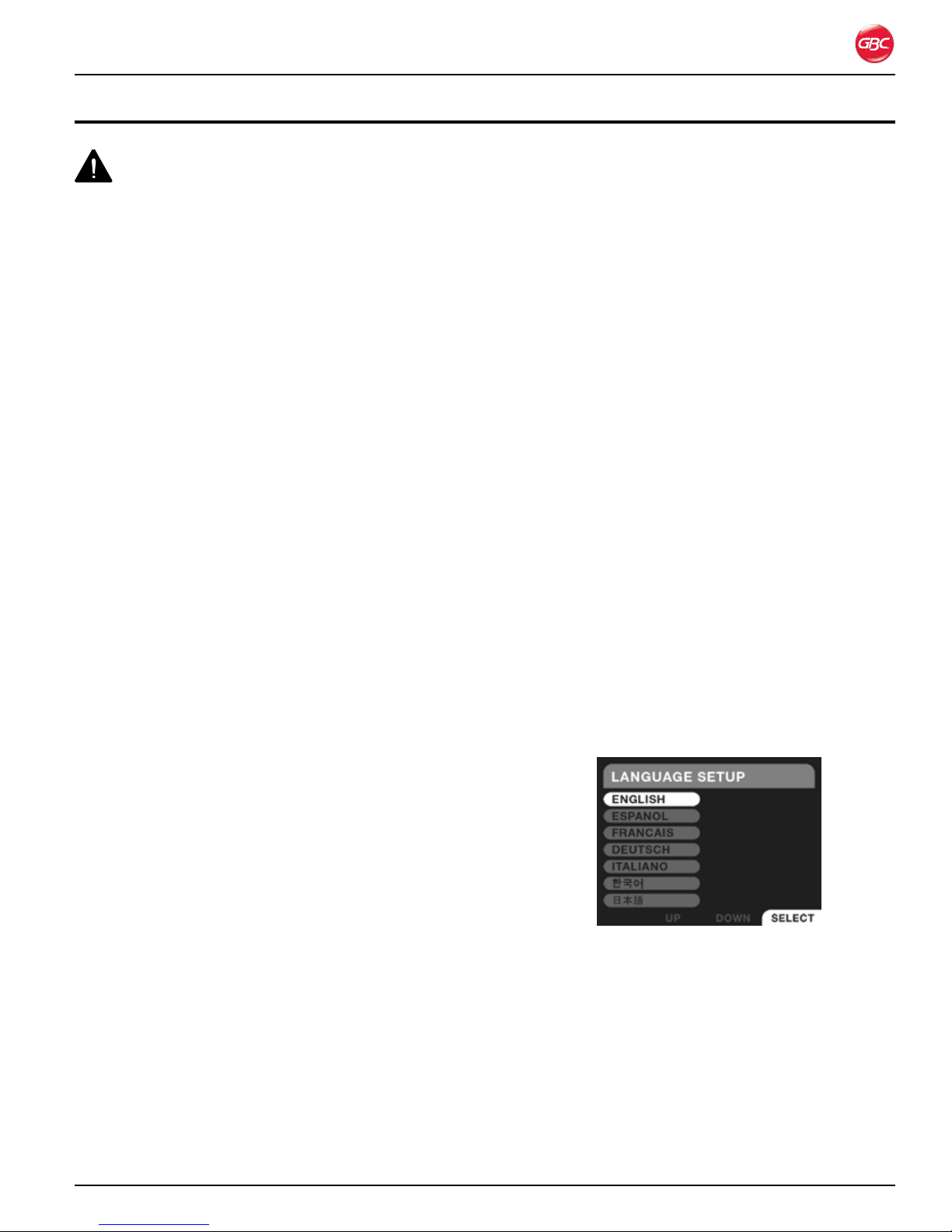
On the Language Setup menu, press UP or DOWN
to scroll to the desired language.
ACCO Br ands Can ada
5 Precidio Cour t
Brampton, ON L6S-6B7
800.263.1063
www.gbccanada.com
Page i
ACCO Mexicana
Neptu no #43, Colo nia Nueva I ndustr ial Vallejo
Delagacion Gus tavo A. Madero, CP 07700
México, DF. (55) 1500-5578
www.gbc.com.mx
© 2011 ACCO Brands. All rights reserved. ACC O® is a regis tered trademark of
ACCO Br ands. GBC ® is a registered trad emark of General Bi nding Cor porati on.
80120510 Rev. A 11-2011
Page 3

Magnapunch 2.0 – Installation and Operating Instructions
Ta b l e o f Co n T e n T s
1. Safety 1-1
General Safeguards ................................................1-1
Die Set Cautions .................................................1-2
Electrical ..................................................................1-2
For 230 Volt Machines Only ................................1-2
GBC Technical Service .......................................... 1-3
Safety Label Locations .......................................... 1-4
2. Warranty 2-1
Limited 90-Day Warranty ........................................2-1
3. Specifications 3-1
Punching Dimensions ........................................ 3-2
FCC Class A Notice ............................................... 3-4
Canada Class A Notice - Avis Canada, Classe A .. 3-4
Modifications .......................................................... 3-4
4. Installation 4-1
GBC Technical Service .......................................... 4-1
Prior to Installation ................................................. 4-1
Installation .............................................................. 4-1
Test ing ................................................................ 4-1
Installing Die Sets .............................................. 6-6
Removing Punch Pins ........................................ 6-7
Job Setup ............................................................... 6-7
Using the LCD User Interface ............................ 6-7
Testing the Job .................................................. 6-9
Punching Operation ..............................................6-10
Punching the Job ..............................................6-10
Punch Activation ...................................................6-11
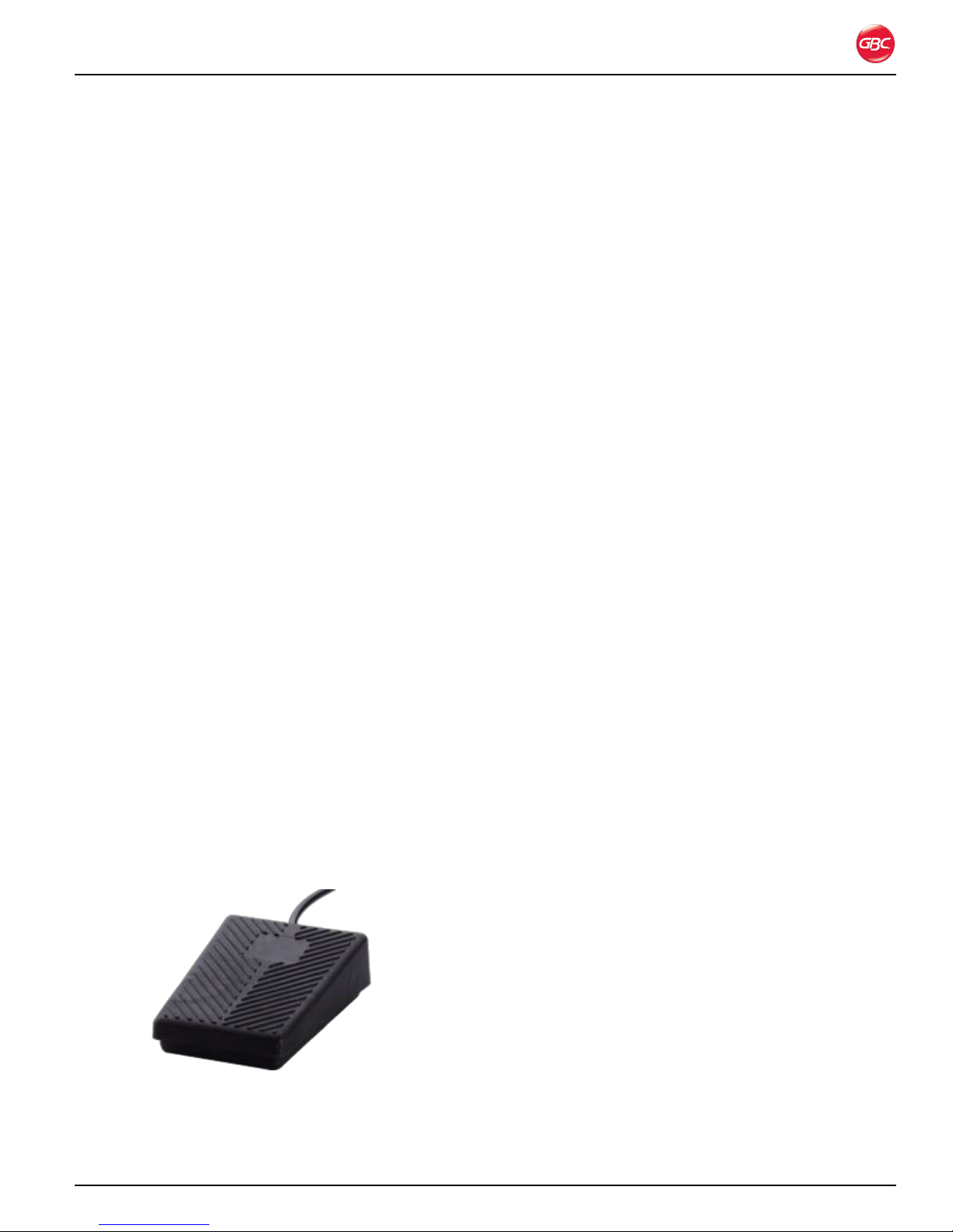
Foot Pedal .........................................................6-11
Tabletop Trigger ................................................6 -11
Punching Tips ......................................................6-12
Paper .................................................................6-12
Plastic Covers ...................................................6 -12
Chip Drawer ......................................................6-12
Hole Quality ...........................................................6-13
7. Operator Maintenance 7-1
Caring for the Magnapunch 2.0 ..............................7-1
Die Set Maintenance .........................................7-1
Cleaning the Magnapunch 2.0 ............................7-1
Troubleshooting ......................................................7-2
Notes 7-3
5. Feature guide 5-1
Power ..................................................................... 5-1
ON/OFF Switch .................................................. 5-1
Fuse ................................................................... 5-1
Power and Foot Pedal Connectors.................... 5-1
Punching Throat ..................................................... 5-1
Lift Picker ............................................................... 5-2
User Interface ......................................................... 5-2
LCD .................................................................... 5-2
Push Buttons ..................................................... 5-2
Edge Guide and Tabletop Trigger .......................... 5-2
Edge Guide ........................................................ 5-2
Tabletop Trigger ................................................. 5-3
Punching Table ....................................................... 5-3
Chip Drawer ....................................................... 5-3
Die Set ............................................................... 5-3
Foot Pedal .......................................................... 5-3
6. Operation 6-1
User Interface ......................................................... 6-2
Navigation .......................................................... 6-2
First Time Setup ................................................. 6-2
Operation ...............................................................6-3
Home Screen ..................................................... 6-3
Menu .................................................................. 6-4
Usage Instructions ............................................. 6-4
Help + Tips .........................................................6-5
Notification Screens .......................................... 6-5
Changing the Interchangeable Die Sets ................6-6
Removing Die Sets ............................................ 6-6
Page ii
Page 4

Magnapunch 2.0 – Installation and Operating Instructions
Page iii
Page 5
Magnapunch 2.0 – Installation and Operating Instructions
1. sa f e t y
Your safety, as well as the safety of others is
important. Before you install or use the Magnapunch
2.0, read and follow all the safety notices carefully
in this chapter. In this instruction manual, and on
the Magnapunch 2.0, you will find important safety
notices regarding the Magnapunch 2.0. Read all
of the instructions and save these instructions for
further use.
The safety alert symbol precedes each
safety notice in this manual. The symbol indicates a
potential personal safety hazard to you or others.
This safety alert symbol indicates a potential
electrical shock. It warns you not to open the
Magnapunch 2.0 and expose yourself to hazardous
voltage.
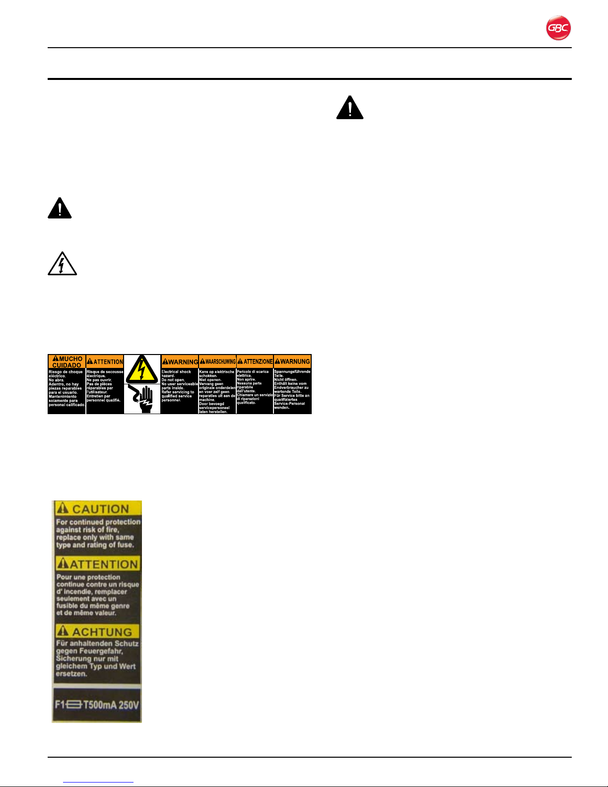
The following warnings are found on the
Magnapunch 2.0.
This safety notice means that you could be seriously
hurt or killed if you open the Magnapunch 2.0 and
expose yourself to hazardous voltage. Do not open
the Magnapunch 2.0. There are no user serviceable
parts inside. Refer service to qualified service
personnel.
This safety notice means that a
fire or risk of electrical shock
could result from using an
improper fuse. For continued
protection against fire or risk of
electrical shock, replace only
with the same type and rating
fuse.
WaRninGs
Do not attempt to service or repair the •
Magnapunch 2.0.
Do not open the Magnapunch 2.0. There are •
no serviceable parts inside. Refer service to
qualified service personnel.
Do not connect the Magnapunch 2.0 to an •
electrical supply or attempt to operate the
Magnapunch 2.0 until you have completely
read these instructions. Maintain these
instructions in a convenient location for future
reference.
To guard against injury, the general safety •
precautions must be observed when installing
and using the Magnapunch 2.0.
Ensure the Power switch is in the OFF position •
when the Magnapunch 2.0 is not in use.
Consider the work area. A cluttered work area •
can lead to accidents. The Magnapunch 2.0
must be placed on a sturdy level table surface.
Allow sufficient access to the front, back, and
sides of the Magnapunch 2.0. Keep the work
area well lit.
Failure to observe these warnings could result in
severe bodily damage or death.
Ge n e R a l sa f e G U a R d s
Do not use the Magnapunch 2.0 for other than •
its intended purposes.
Do not defeat or remove electrical and •
mechanical safety equipment such as
interlocks, shields, and guards.
Do not insert objects unsuitable for punching •
or expose the equipment to liquids.
Use only GBC Magnapunch 2.0 •
interchangeable Die Sets with the
Magnapunch 2.0.
Before you operate this Magnapunch 2.0, it is •
important that you read and understand the
entire contents of these instructions.
Page 1-1
Page 6
Magnapunch 2.0 – Installation and Operating Instructions
die se t Ca U t i o n s
CAUTIONS:
Possible pinch point hazard. When installing Die •
Sets into your Magnapunch 2.0, always keep
fingers and body parts out of the Magnapunch
2.0’s Die Set slot and away from all areas of the
Die Set except for the finger groove in the Die
Set’s handle. Failure to observe these precautions
may result in injury.
Possible Die Set damage. Make certain that all •
punch pins are fully and properly seated in the Die
Set before inserting the Die Set. Failure to ensure
that all punch pins are fully seated could result in
damage to the Die Set and Magnapunch 2.0.
el e C t R i C a l
The Magnapunch 2.0 should be connected only to
a source of power as indicated in these instructions
and on the nomenclature plate located on the rear of
the Magnapunch 2.0. Contact an electrician should
the attachment plug provided with the Magnapunch
2.0 not match the receptacles at your location.
Disconnect the plug from the receptacle and contact
your dealer or distributor, or GBC Technical Service
when one or more of the following has occurred.
The power supply cord or attachment plug is •
damaged.
Liquid has been spilled into the Magnapunch •
2.0.
The Magnapunch 2.0 is malfunctioning.•
The Magnapunch 2.0 does not operate as •
described in these instructions.
CAUTION: The receptacle must be located
near the Magnapunch 2.0 and must be easily
accessible.
Disconnect the attachment plug from the receptacle
to which it is connected and keep the power
supply cord in your possession while moving the
Magnapunch 2.0.
fo R 230 vo l t Ma C h i n e s on l y
CAUTION: When choosing a detachable
line cord for use with your Magnapunch 2.0, always
observe the following.
WARNING: Do not attempt to service or repair
the Magnapunch 2.0. Failure to observe this warning
could result severe personal injury or death.
Make sure the power switch is in the Off position
when the Magnapunch 2.0 is not in use.
The cordset consists of three parts; •
attachment plug, cordage, and appliance
inlet. Each of these components must have
European regulatory approvals for safety.
The following minimum electrical ratings •
for the specific cordset are published for
safety purposes. Do not use cordsets that
do not meet the following minimum electrical
requirements.
Plug: 10 amperes, 250 volts, 50/60 Hz,
European safety approved.
Cordage: Type HO5VV-F3G0.75, harmonized
( HAR ). The symbols indicate cordage
approved to appropriate European standard.
Note, HAR may be substituted by the approval
mark of the European Safety agency which
approved the cordage. An example would be
VDE .
Appliance Connector: 10 amperes, 250 volts,
50/60 Hz, European safety approved, Type IEC
320.
The cordset shall not exceed 3 meters in
length. A cordset with component electrical
ratings greater than the minimum specified
electrical ratings may be substituted.
Page 1-2
Page 7

Magnapunch 2.0 – Installation and Operating Instructions
GBC te C h n i C a l se R v i C e
To order replacement accessories, service, parts,
or an Equipment Maintenance Agreement, please
contact GBC Technical Service and Support at:
United States
GBC Technical Service and Support – 3rd Floor
ACCO Brands
300 Tower Parkway
Lincolnshire, IL 60069
www.gbcconnect.com
1-800-723-4000
Canada
ACCO Brands Canada
5 Precidio Court
Brampton, ON L6S-6B7
www.gbccanada.com
Callcentre@GBCCanada.com
1-800-463-2545
Mexico
ACCO Mexicana
Neptuno #43, Colonia Nueva Industrial Vallejo
Delagacion Gustavo A. Madero, CP 07700
México, DF. (55) 1500-5578
www.accomexico.mx/index.php
(5525) 1500-5741
Other Sources
For service facilities in other regions, please visit:
www.gbcconnect.com/contact_us.aspx
Also use your mobile phone to scan the QR code
on the side of the Magnapunch 2.0 for a list of
authorized service providers.
Page 1-3
Page 8
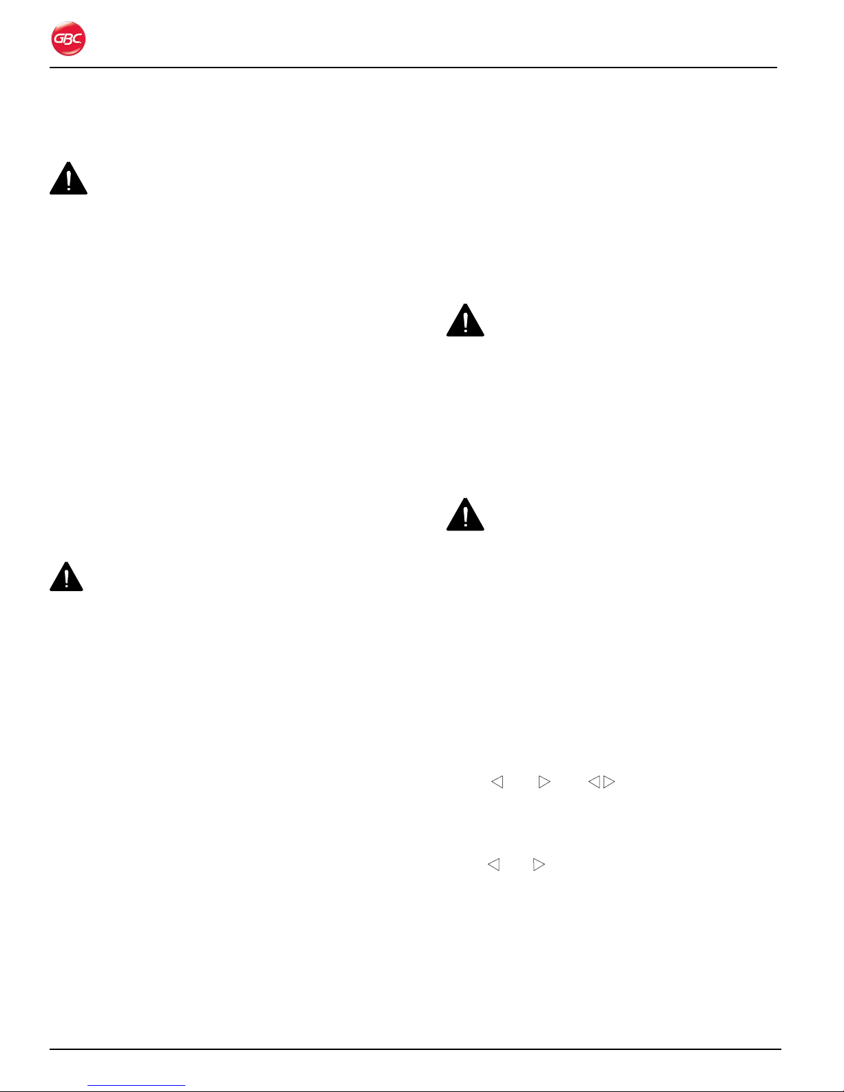
sa f e t y la B e l lo C a t i o n s
Magnapunch 2.0 – Installation and Operating Instructions
Page 1-4
Magnapunch 2.0 Safety Label Locations.Figure 1.
Page 9

Magnapunch 2.0 – Installation and Operating Instructions
2. Wa R R a n t y
li M i t e d 90-da y Wa R R a n t y
ACCO Brands USA LLC, 300 Tower Parkway,
Lincolnshire, IL 60069 (in Canada, ACCO Brands
Canada Inc., 5 Precidio Court, Brampton, ON
L6S-6B7; and in Mexico, ACCO Mexicana, S.A. de
C.V. Av., Circuito Industrial Norte #6 Parque Industrial
Lerma 52000, Lerma Edo. De México) (each,
respectively, “ACCO Brands”) warrants to the original
purchaser that this Magnapunch 2.0 ACCO Brands
product is free from defects in workmanship and
material under normal use and service for a period of
90 days after purchase.
ACCO Brands’ obligation under this warranty is
limited to replacement or repair, at ACCO Brands’
option, of any warranted part found defective by
ACCO Brands without charge for material or labor.
Any replacement, at ACCO Brands’ option, may be
the same product or a substantially similar product
that may contain remanufactured or refurbished
parts. This warranty shall be void in the following
circumstances:
(i) if the product has been misused,
(ii) if the product has been damaged by negligence
or accident, or
(iii) if the product has been altered by anyone other
than ACCO Brands or ACCO Brands’ authorized
agents.
For warranty execution, please contact ACCO
Brands at:
1-800-541-0094 or www.gbcconnect.com in the
USA
800-263-1063 or www.gbccanada.com in Canada
TO THE EXTENT ALLOWED BY APPLICABLE
LAW, THIS WARRANTY IS IN LIEU OF ALL OTHER
EXPRESSED WARRANTIES. REPRESENTATIONS
OR PROMISES INCONSISTENT WITH OR
IN ADDITION TO THIS WARRANTY ARE
UNAUTHORIZED AND SHALL NOT BE BINDING ON
ACCO BRANDS. TO THE EXTENT PERMITTED BY
APPLICABLE LAWS, ANY IMPLIED WARRANTIES
(IF APPLICABLE) ARE LIMITED IN DURATION
TO THE DURATION OF THIS WARRANTY.
SOME STATES AND JURISDICTIONS DO NOT
ALLOW LIMITATIONS ON HOW LONG AN
IMPLIED WARRANTY LASTS, SO THE ABOVE
LIMITATION MAY NOT APPLY TO YOU. TO THE
EXTENT PERMITTED BY APPLICABLE LAW, IN
NO EVENT SHALL ACCO BRANDS BE LIABLE
FOR ANY SPECIAL, INCIDENTAL, PUNITIVE,
EXEMPLARY, CONSEQUENTIAL OR SIMILAR
DAMAGES, WHETHER OR NOT FORESEEABLE.
SOME STATES AND JURISDICTIONS DO NOT
ALLOW THE EXCLUSION OR LIMITATION OF
SPECIAL, INCIDENTAL, PUNITIVE, EXEMPLARY,
CONSEQUENTIAL, OR SIMILAR DAMAGES, SO
THE ABOVE EXCLUSION OR LIMITATION MAY NOT
APPLY TO YOU.
FOR CONSUMERS WHO HAVE THE BENEFIT
OF CONSUMER PROTECTION LAWS OR
REGULATIONS IN THEIR JURISDICTION OF
PURCHASE OR, IF DIFFERENT, IN THEIR
JURISDICTION OF RESIDENCE, THE BENEFITS
CONFERRED BY THIS WARRANTY ARE IN
ADDITION TO ALL RIGHTS AND REMEDIES
CONVEYED BY SUCH CONSUMER PROTECTION
LAWS AND REGULATIONS.
To the extent permitted by law, this warranty is
not transferable and will automatically terminate if
the original product purchaser sells or otherwise
disposes of the product.
(55) 1500-5578 or www.gbc.com.mx in Mexico
This warranty gives you specific legal rights. Other
rights, which vary from jurisdiction to jurisdiction,
may exist. In addition some jurisdictions do not allow
(i) the exclusion of certain warranties, (ii) limitations
on how long an implied warranty lasts and/or (iii) the
exclusion or limitation of certain types of costs and/
or damages, so the above limitations may not apply.
Page 2-1
Page 10

Magnapunch 2.0 – Installation and Operating Instructions
Page 2-2
Page 11
Magnapunch 2.0 – Installation and Operating Instructions
Width
Depth
Height
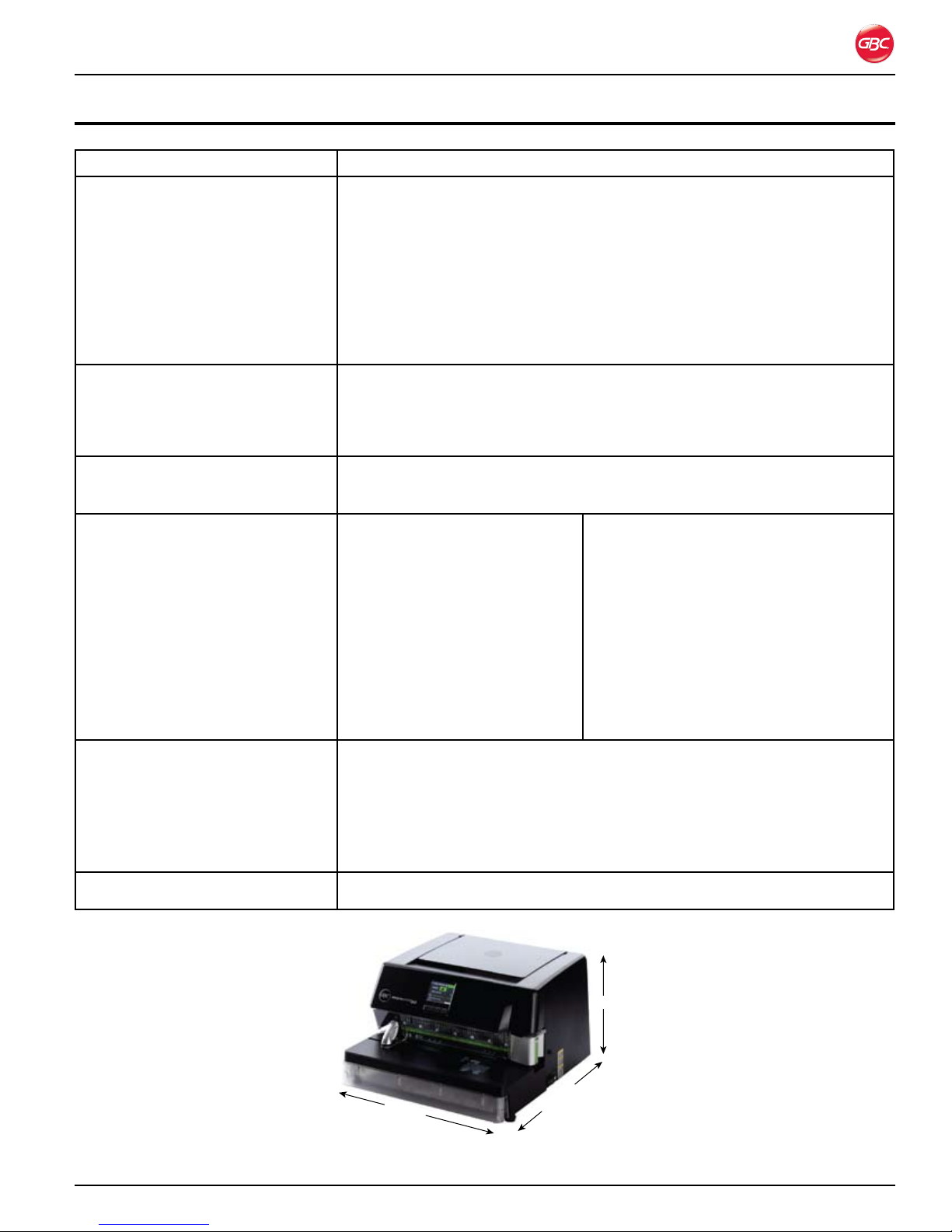
3. speCifiCations
Item Specification
Punch Pattern
Plastic Binding•
Plastic Color Coil, GBC and •
Industry standard 4:1 (C4)
Plastic Color Coil, 5:1 (C5)•
Twin Loop Wire, 2:1 (W2)•
Twin Loop Wire, 3:1 (W3)•
VeloBind•
SureBind•
3 or 4 Hole Binding•
Maximum number of sheet punch capacity for 20 lb. (75 g/m2) bond.
39
29
29
29
34 (round) 29 (square)
34 (round) 29 (square)
49
49
34
Dimensions
Width•
Height•
Depth•
18.5 in. (47.0 cm)
12.0 in. (30.5 cm)
20.0 in. (50.8 cm)
Weight
Machine•
Shipping•
Electrical Requirements
Fuse (F1 T1A 250V)•
Voltage•
Current•
Power•
U.S. Receptacle•
94 lbs. (42.4 kg)
116 lbs. (52.6 kg)
US Model
20A, 250V
115 VAC
5.6 Amperes maximum, 50/60
Hz
644 W
NEMA 5-15R
Refer to the nomenclature
plate located on the rear of the
Magnapunch 2.0 for the specific
Europe Model
20A, 250V
230 VAC
3.5 Amperes maximum, 50/60 Hz
805 W
YP-24 R
Refer to the nomenclature plate located
on the rear of the Magnapunch 2.0 for the
specific electrical rating applicable to the
unit.
electrical rating applicable to the
unit.
Noise Level 94dB when punching maximum pages of media.
Under 2003/10/EC on the minimum health and safety requirements regarding
the exposure of workers to the risks arising from physical agents (noise), the
following sound pressure levels require the following action by employers:
80dB employers must make hearing protection available to workers. •
85dB a hearing protection warning sign must be displayed. •
87dB individual hearing protection shall be used by workers.•
Motor 1/4 HP
Width
Height
Depth
Dimension Reference.Figure 2.
Page 3-1
Page 12

Magnapunch 2.0 – Installation and Operating Instructions
pU n C h i n G di M e n s i o n s
Punch Pattern Maximum Punch Length Number of Punch Pins Center to Center Hole
Spacing
Plastic binding 14 in. (356 mm) 25 0.5625 in. (14.29 mm)
Plastic Color Coil, GBC 4:1 (C4) 14 in. (356 mm) 55 0.2475 in. (6.29 mm)
Plastic Color Coil, industry
standard 4:1 (C4)
Plastic Color Coil, 5:1 (C5) 14 in. (356 mm) 69 0.20 in. (12.70 mm)
Twin loop wire 2:1 (W2) 14 in. (356 mm) 27 0.50 in. (12.70 mm)
Twin loop wire 3:1 (W3) 14 in. (356 mm) 41 0.3333 in. (8.47 mm)
ProClick 3:1 square 12 in. (305 mm) 34 0.3333 in. (8.47 mm)
VeloBind
SureBind
3 or 4 hole binding Varies Up to 7 or 4 Varies
®
®
14 in. (356 mm) 55 0.25 in. (6.35 mm)
15 in. (381 mm) 14 1.0 in. (25.40 mm)
14 in. (356 mm) 12 Varies
Page 3-2
Page 13

Magnapunch 2.0 – Installation and Operating Instructions
Page 3-3
Page 14

Magnapunch 2.0 – Installation and Operating Instructions
fCC Cl a s s a no t i C e
This device complies with Part 15 of the FCC Rules.
Operation is subject to the following two conditions:
This device may not cause harmful •
interference.
This device must accept any interference •
received, including interference that may
cause undesired operation.
Note: This equipment has been tested and found to
comply with the limits for a Class A digital device,
pursuant to Part 15 of the FCC rules. These limits are
designed to provide reasonable protection against
harmful interference when the equipment is operated
in a commercial environment. This equipment
generates, uses and can radiate radio frequency
energy and, if not installed and used in accordance
with the instruction manual, may cause harmful
interference to radio communications. Operation
of this equipment in a residential area is likely to
cause harmful interference in which case the user
will be required to correct the interference at his own
expense.
Mo d i f i C a t i o n s
Any modifications made to this device that are not
approved by ACCO Brands Corporation may void the
authority granted to the user by the FCC and/or by
Industry Canada to operate this equipment.
Toutes modifications apportées à ce dispositif et
non approuvées par ACCO Brands Corporation
annuleront le droit accordé à l’utilisateur par le FCC
et/ou par Industrie Canada de faire fonctionner cet
équipement.
Ca n a d a Cl a s s a no t i C e - av i s
Ca n a d a , Cl a s s e a
This Class A digital apparatus complies with
Canadian ICES-003.
Cet appareil numérique de la classe B est conforme
à la norme NMB-003 du Canada.
Page 3-4
Page 15
Magnapunch 2.0 – Installation and Operating Instructions
4. in s t a l l a t i o n
WARNING: Do not attempt to service or repair
the Magnapunch 2.0. Failure to observe this warning
could result in severe personal injury or death.
Disconnect the plug from the receptacle and contact
GBC Technical Service when one or more of the
following has occurred.
The power supply cord or attachment plug is •
damaged.
Liquid has been spilled into the Magnapunch •
2.0.
The Magnapunch 2.0 is malfunctioning.•
The Magnapunch 2.0 does not operate as •
described in these instructions.
GBC te C h n i C a l se R v i C e
United States
1-800-723-4000
Canada
1-800-463-2545
Mexico
(5525) 1500-5741
Other Sources
For service facilities in other regions, please visit:
www.gbcconnect.com/contact_us.aspx
Also use your mobile phone to scan the QR code
on the side of the Magnapunch 2.0 for a list of
authorized service providers.
To set up the Magnapunch 2.0 for the first time:
Place the Magnapunch 2.0 on a stable flat 1.
surface capable of supporting the weight of the
Magnapunch 2.0. An additional work surface
near the Magnapunch 2.0 is recommended for
items to be punched.
The Magnapunch 2.0 should be located near the 2.
electrical power with sufficient space behind and
above it to allow for ventilation. Adequate space
above the punch is required to open the top lid
and for staging the paper to be punched.
Connect the attachment plug provided with the 3.
Magnapunch 2.0 to a suitably grounded outlet
only. Avoid connecting other equipment to the
same branch circuit to which the Magnapunch
2.0 is connected, as this may result in nuisance
tripping of circuit breakers or blowing fuses.
Connect the Foot Pedal to the rear of the 4.
Magnapunch 2.0 and place the Foot Pedal on the
floor within easy reach of your foot.
te s t i n G
After the Magnapunch 2.0 has been properly
installed, it must be tested to ensure proper
operation.
Notes:
The first time the Magnapunch 2.0 is •
powered-up, a setup screen appears. Select
the language and then measurement units.
pR i o R t o in s t a l l a t i o n
Inspect the packaging and Magnapunch 2.0 for
damage. Shipping damage should be brought to the
immediate attention of the delivering carrier.
The Magnapunch 2.0 weighs 94 lbs. (42.4 kg). Two
people are required to lift and move the punch.
in s t a l l a t i o n
To unpack the Magnapunch 2.0:
Cut the plastic shipping straps and the packing 1.
tape.
Remove the Magnapunch 2.0 from the shipping 2.
carton. Use the cut outs in the cardboard base
pad to indicate where to place your hands.
Language setup screen.Figure 3.
A Die Set must be installed before running the •
Magnapunch 2.0.
To test the Magnapunch 2.0:
Punch 10 sheets of 20 lb. (75 g/m1.
in one lift.
Punch five sheets of 20 lb. (75 g/m2.
to check for a clean hole punch.
If using a PB Die Set, Punch 10 sheets of 20 lb. 3.
(75 g/m2) bond paper at each back gauge setting
to ensure three distinct positions.
2
) bond paper
2
) bond paper
Page 4-1
Page 16

Magnapunch 2.0 – Installation and Operating Instructions
Page 4-2
Page 17
Magnapunch 2.0 – Installation and Operating Instructions
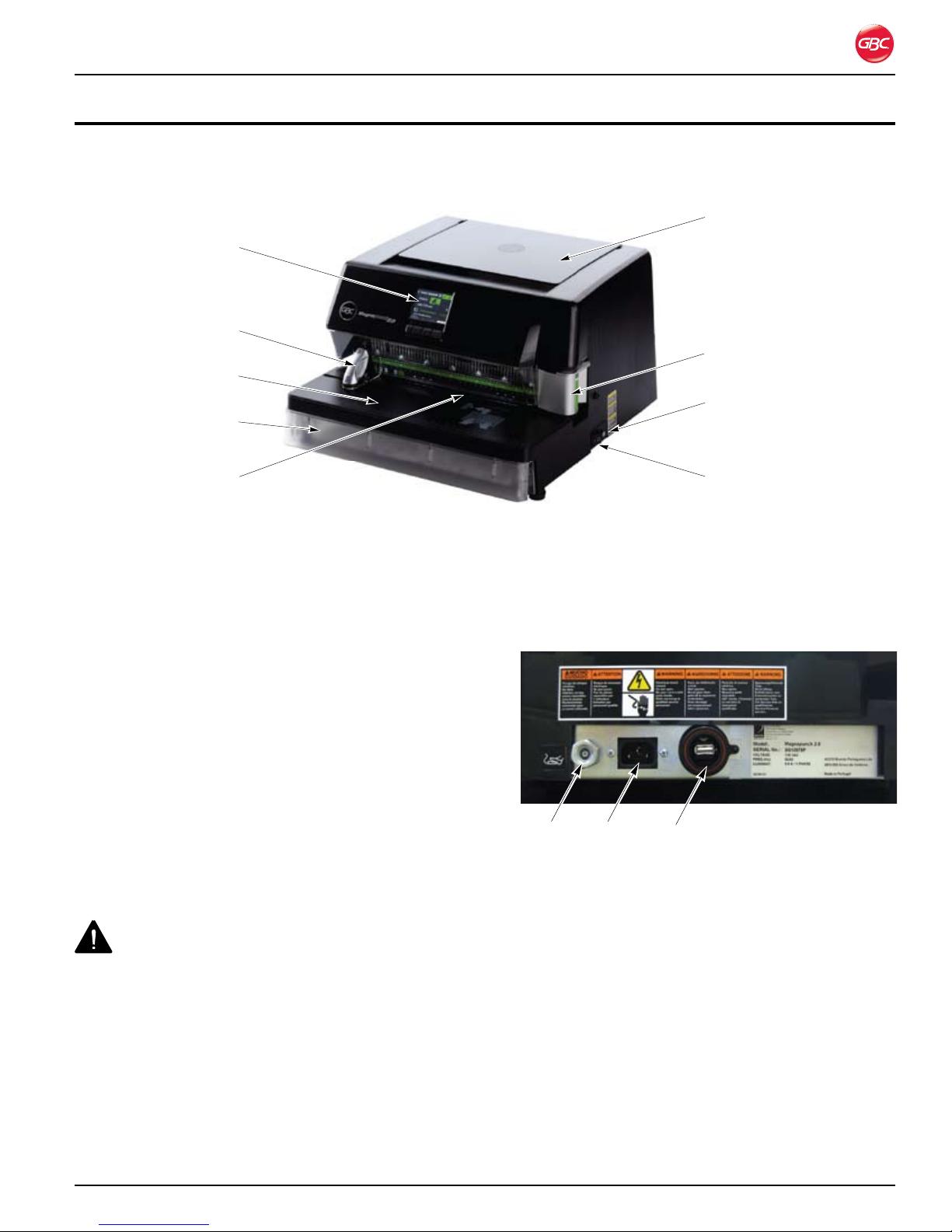
5. fe a t U R e G U i d e
This chapter helps you identify the main components of the Magnapunch 2.0.
User Interface
Edge Guide and
Tabletop Trigger
Punching Table
Chip Drawer
Lift picker
Die Set
Fuse
Punching Throat
Magnapunch 2.0 Identification. Figure 4.
po W e R
on/off sW i t C h
Use the ON/OFF switch to turn the Magnapunch
2.0 on and off. Press the ON/OFF switch to the I
position to turn the Magnapunch 2.0 On. Press
the ON/OFF switch to the O position to turn the
Magnapunch 2.0 Off.
fU s e
One fuse protects the Magnapunch 2.0 and its
electrical components from current that is higher
than the Magnapunch 2.0 is rated for.
CAUTION: For continued protection against
fire or risk of electrical shock, replace only with the
same type and rating fuse.
ON/OFF switch
po W e R a n d fo o t pe d a l Co n n e C t o R s
PowerFoot Pedal Service port
Connections on Back of Magnapunch 2.0.Figure 5.
The Power Cord plugs into a standard US 115 VAC
NEMA 5-15R (European 230 VAC YP-24 10 to 16
Amp) wall outlet.
pU n C h i n G th R o a t
To replace a fuse, insert a flat blade screwdriver
into the fuse cover, push, and then turn counterclockwise. Replace the fuse, insert into the fuse
holder, and turn it clockwise.
The Punching Throat is where the media’s edge to be
punched is inserted during the punching process.
NOTE: Do not force more media into the throat than
will fit easily.
Page 5-1
Page 18
Magnapunch 2.0 – Installation and Operating Instructions
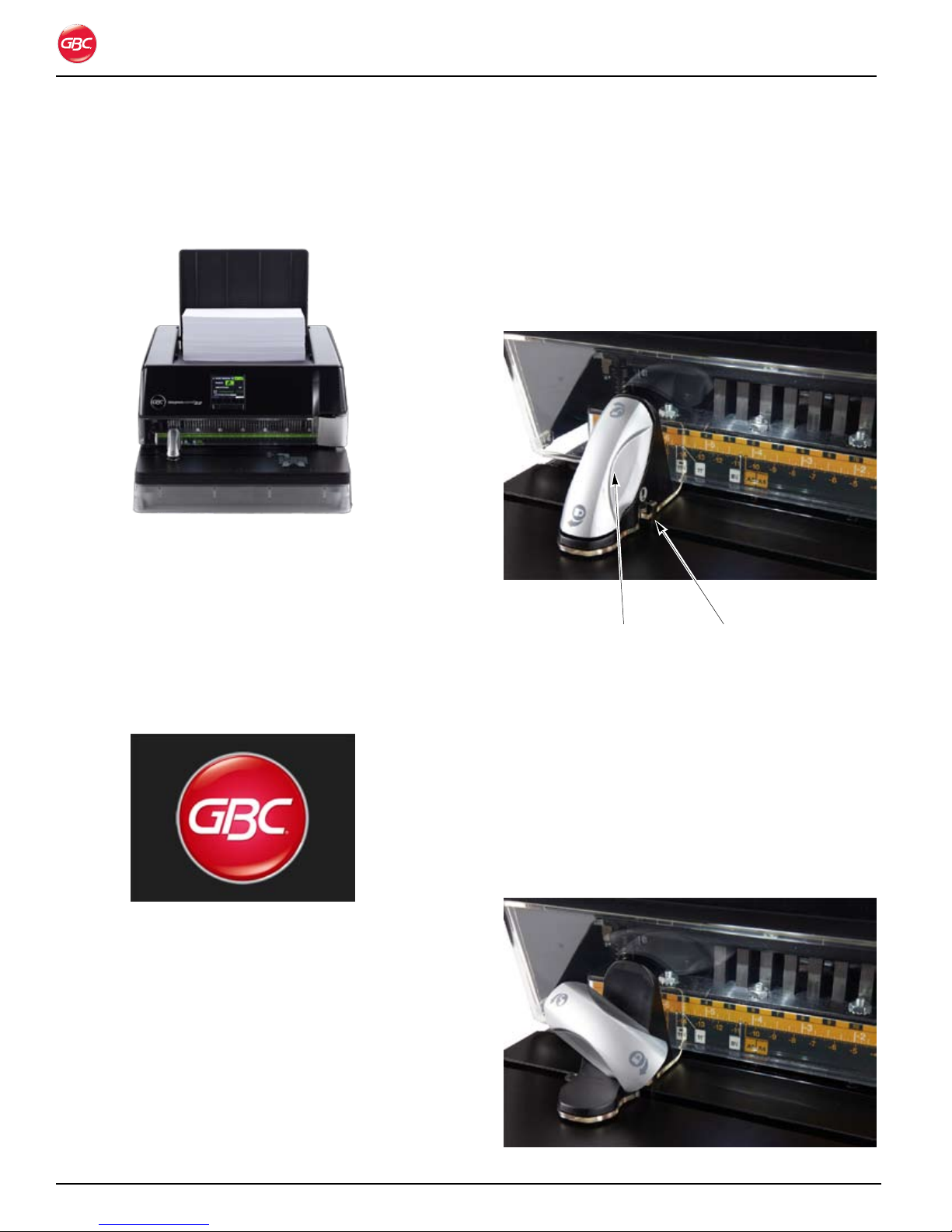
li f t pi C k e R
Raise the lid of the Lift Picker to stack media that has
been punched or that is to be punched.
Magnapunch 2.0 with Media in Lift Picker.Figure 6.
Us e R in t e R f a C e
The User Interface (UI) consists of an LCD and four
buttons below the LCD. The LCD displays system
messages and provides access to operational
functions. The push buttons below the LCD are used
to navigate through the menus, select items, and
commit commands.
pU s h BU t t o n s
The Push Buttons relate to the commands at the
bottom of the LCD. The action of the button may
change depending on the menu on the LCD.
ed G e GU i d e a n d ta B l e t o p
tR i G G e R
Edge Guide
adjustment handle
Edge Guide and Tabletop Trigger.Figure 8.
ed G e GU i d e
Tabletop Trigger
Start Up Screen.Figure 7.
lCd
The LCD provides continuous status of the
Magnapunch 2.0 and includes step by step
instructions on how to use your Magnapunch 2.0.
The Edge Guide sets the position for a variety of
punching patterns and paper sizes.
Turn the Edge Guide handle 1/4 turn
counter-clockwise to unlock. Move the Edge Guide
to line up with the desired setting on the Die Set and
then turn the handle clockwise 1/4 turn to lock the
Edge Guide in place.
Edge Guide Unlocked.Figure 9.
Page 5-2
Page 19
Magnapunch 2.0 – Installation and Operating Instructions
ta B l e t o p tR i G G e R
The Tabletop Trigger is incorporated into the Edge
Guide. The Tabletop Trigger is used to automatically
punch without the use of the Foot Pedal. The
Tabletop Trigger is activated on the Home screen of
the User Interface.
Push the stack of media into the Throat and then
slide to the left against the Trigger to activate the
punch.
pU n C h i n G ta B l e
The Punching Table is where you lay the media to be
punched. Place the media on the Punching Table,
push the media into the Throat, and then slide to the
left.
Ch i p dR a W e R
The Chip Drawer collects the paper chips from
the punched media. When the Chip Drawer is full,
a message on the LCD UI alerts you to empty the
drawer.
die se t
The Magnapunch 2.0 offers thirteen different Die
Sets to match the punching requirements for your
documents. To change a Die Set, refer to “Changing
the Interchangeable Die Sets”.
fo o t pe d a l
The Foot Switch is activated on the Home Screen.
When media is inserted into the Punching Throat
and pushed against the Edge Guide, press the Foot
Pedal to activate the punch.
Foot Pedal.Figure 10.
Page 5-3
Page 20

Magnapunch 2.0 – Installation and Operating Instructions
Page 5-4
Page 21
Magnapunch 2.0 – Installation and Operating Instructions
6. op e R a t i o n
The Magnapunch 2.0 uses a variety of easily
interchangeable Die Sets for different binding styles.
By selecting the appropriate Die Set, you can use
your Magnapunch 2.0 to punch documents in any of
the binding styles indicated in the following table.
Punch StylesTable 1.
Minimum Margin
Binding Style Punch Pattern
CombBind
Color Coil
Color Coil
Color Coil 5:1 (5 holes per inch)
WireBind
WireBind
VeloBind 1 hole per inch 0.500 in. (12.7 mm)
SureBind
3, 5, or 7 Hole Binding 11 in. 3 holes across bound edge of document, 11 inch paper
2 or 4 Hole Binding A4 4 holes across bound edge of document, A4 paper
®
®
®
®
Cerlox (Plastic Comb, Plastic Binding)
4:1 GBC (4 holes per inch 0.2475” center-to-center hole spacing)
4:1 Industry Standard (4 holes per inch, 0.2500” center-to-center
hole spacing)
2:1 (2 holes per inch) Both square and round hole patterns
available.
3:1 (3 holes per inch) Both square and round hole patterns
available.
Approximately 1 hole per inch
to First Binding
Hole
0.282 in. (7.2 mm)
0.092 in. (2.6 mm)
0.040 in. (1.0 mm)
1 0.030 in.
(0.8 mm)
0.375 in. (9.5 mm)
0.261 in. (6.6 mm)
0.531 in. (13.5 mm)
Note: Each punching style listed in the table requires
a separate Die Set for the Magnapunch 2.0. Custom
Die Sets for special punching patterns (not listed
above) can also be made to your specifications. For
more information on custom Die Sets, contact your
local GBC sales representative.
IMPORTANT: A decal on the handle of each
interchangeable Die Set indicates the punching
pattern for that Die Set. When reading the Operating
Instructions, please note the special instructions for
the correct punching pattern Die Set that you have
installed in your Magnapunch 2.0.
WARNING: Do not attempt to service or repair
the Magnapunch 2.0. Failure to observe this warning
could result severe personal injury or death.
Disconnect the plug from the receptacle and contact
your dealer or distributor, or GBC Technical Service
at one of the numbers below when one or more of
the following has occurred.
The power supply cord or attachment plug is •
damaged.
Liquid has been spilled into the Magnapunch •
2.0.
The Magnapunch 2.0 is malfunctioning.•
The Magnapunch 2.0 does not operate as •
described in these instructions.
US - 800-723-4000
Canada - 800-463-2545
Mexico - (5525) 1500-5741
CAUTION:
The receptacle must be located near •
the Magnapunch 2.0 and must be easily
accessible.
Disconnect the attachment plug from the •
receptacle to which it is connected and keep
the power supply cord in your possession
while moving the Magnapunch 2.0.
Do not use the Magnapunch 2.0 for other than •
its intended purposes.
Do not defeat or remove electrical and •
mechanical safety equipment such as shields
and guards.
Do not insert objects unsuitable for punching •
or expose the equipment to liquids.
Use only GBC Magnapunch 2.0 •
interchangeable Die Sets with the
Magnapunch 2.0.
Failure to observe these warnings could result in
severe bodily damage or death.
Page 6-1
Page 22
Magnapunch 2.0 – Installation and Operating Instructions
Us e R in t e R f a C e
The LCD and the row of buttons below it make up
the user interface (UI). The LCD provides the current
status and settings of the Magnapunch 2.0, and
provides setup and operation instructions for using
your Magnapunch 2.0
nav iGation
Use the buttons on the keypad to move between
menus, scroll, and make selections. The action of the
buttons is shown on the LCD.
When the Magnapunch 2.0 is turned on, the Start up
screen briefly displays, followed by the Home screen.
LCD
fi R s t ti M e se t U p
The first time the Magnapunch 2.0 starts up, you
need to set the language and unit of measure that
will be used on the menus. After the start-up screen
displays briefly, the Language Setup screen displays.
After you perform the setup, these screens do not
display. You can access them from the Home screen
any time by selecting MENU from the Home Screen
and then selecting SETUP feature from the MENU
options..
To set the language and units:
Turn On the Magnapunch 2.0.1.
Keypad
User Interface and Home screen.Figure 11.
HOME Returns to the Home screen.
UP Scrolls up through options.
When the selection gets to the top of
the options, it returns to the bottom
of the list.
BACK Goes back one screen.
DOWN Scrolls down through options. When
the selection gets to the bottom of
the options, it returns to the top of
the list.
NEXT Goes forward one screen.
SELECT Selects or commits menu selection.
MENU Displays an instructional menu.
When the Magnapunch 2.0 has been inactive for
more than 30 minutes, the LCD goes to the Start up
screen and “sleeps.” To “wake” up the LCD, press
any key.
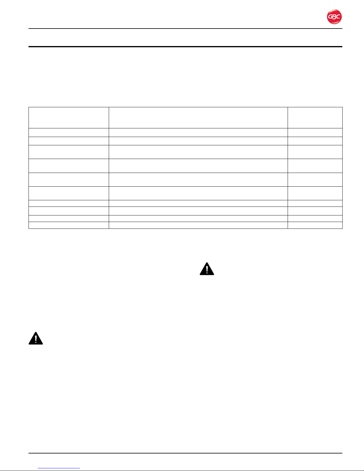
Language Setup Screen.Figure 12.
On the Language Setup menu, press 2. UP or
DOWN to scroll to the desired language.
Press 3. SELECT to select the language.
Unit Selection ScreenFigure 13.
On the Unit Selection screen, press 4. UP or
DOWN to select CM or INCHES.
Press 5. SELECT.
Press 6. HOME to return to the Home screen.
Page 6-2
Page 23
Magnapunch 2.0 – Installation and Operating Instructions
op e R a t i o n
After the Magnapunch 2.0 has been turned on, the
Home screen displays. It is the menu from which you
set up and operate the Magnapunch 2.0. To return to
this menu from any other screen, press HOME.
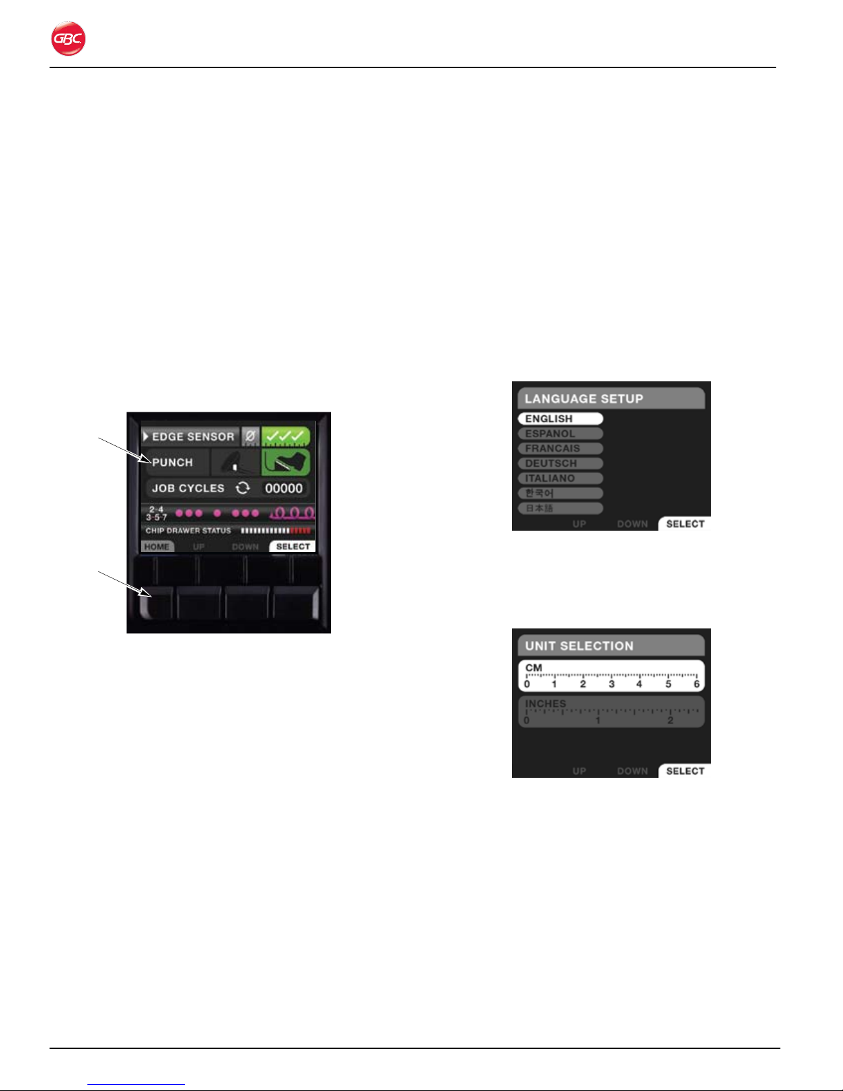
ho M e sC R e e n
The Home screen displays the current status and
operational settings of the Magnapunch 2.0.
Use • UP and DOWN to scroll to each item on
the menu.
Press • SELECT to select the item or command
the Magnapunch 2.0 to do something.
Home Screen with Edge Sensor and Foot Pedal Figure 14.
On.
Edge Sensor
The Edge Sensor virtually eliminates mis-punches by
preventing the punch to cycle when the media is not
fully inserted in the Punch Throat.
The Edge Sensor is On when the checkmarks
are highlighted in green and Off when the O is
highlighted in blue.
To turn On the Edge Sensor:
Use 1. UP and DOWN to scroll to EDGE SENSOR.
Press 2. SELECT to toggle between the settings.
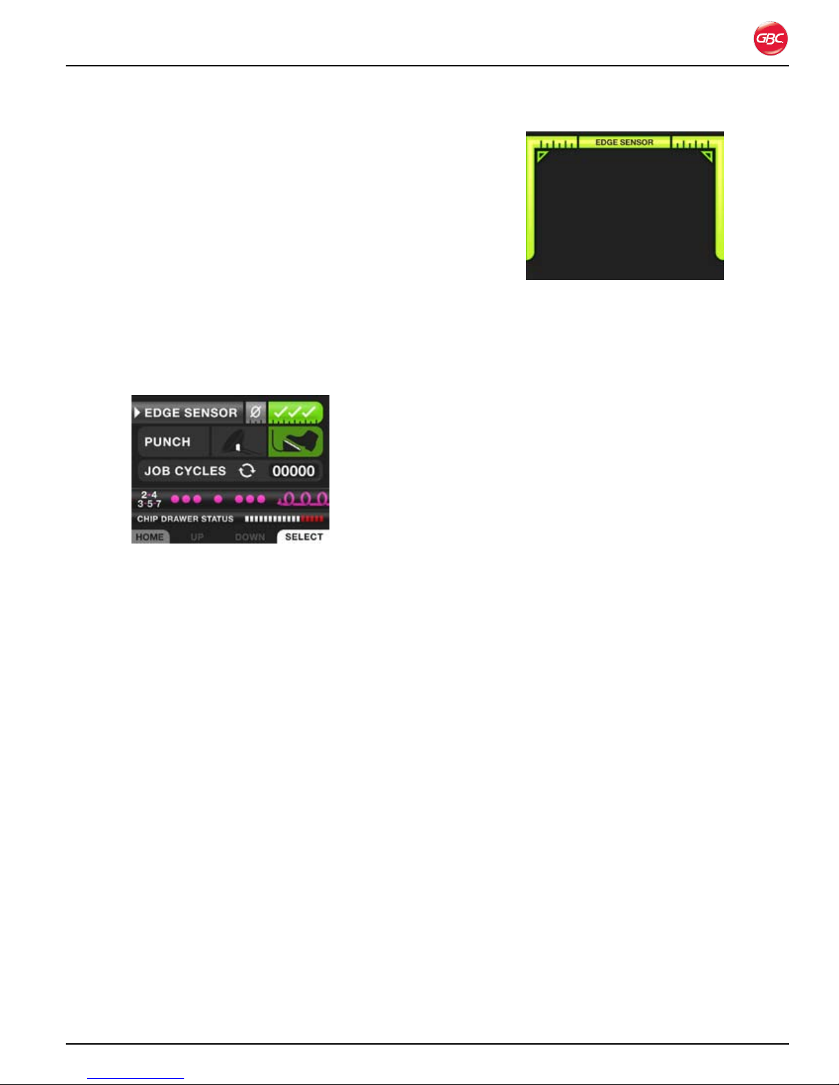
Edge Sensor Screen Indicating Correct Figure 15.
Alignment.
If the punch is triggered when only the left or right
bar is displayed, the punch will not trigger and an
ALERT EDGE SENSOR Error displays. When this
occurs, allow the Magnapunch 2.0 1-2 seconds to
clear and continue punching.
Note: When punching documents less than 6.5 (16.5
cm)inches, the turn OFF the Edge Sensor.
Punch
The punch is activated by the Tabletop Trigger or the
Foot Pedal. The selected mode appears green.
On the Home screen use the up and down keys until
the PUNCH mode is selected. The mode selected
is represented by the white arrow on the left. With
Tabeltop Trigger or Foot Pedal selected, press
SELECT to toggle between the two options.
Job Cycles
Job Cycles displays the number of punch cycles
for individual jobs. You can reset the counter on the
Reset Count screen. To exit the Job Cycles screen
without resetting the count, select EXIT and then
press SELECT.
Edge Sensor Screen
When the Edge Sensor is turned On, the
Magnapunch 2.0 detects when the media is properly
inserted in the Punch Throat. Green bars are
displayed on the User Interface to represent that
both the left and right edge of the media are fully
insert. When both bars are displayed, activate the
punch.
Page 6-3
Page 24
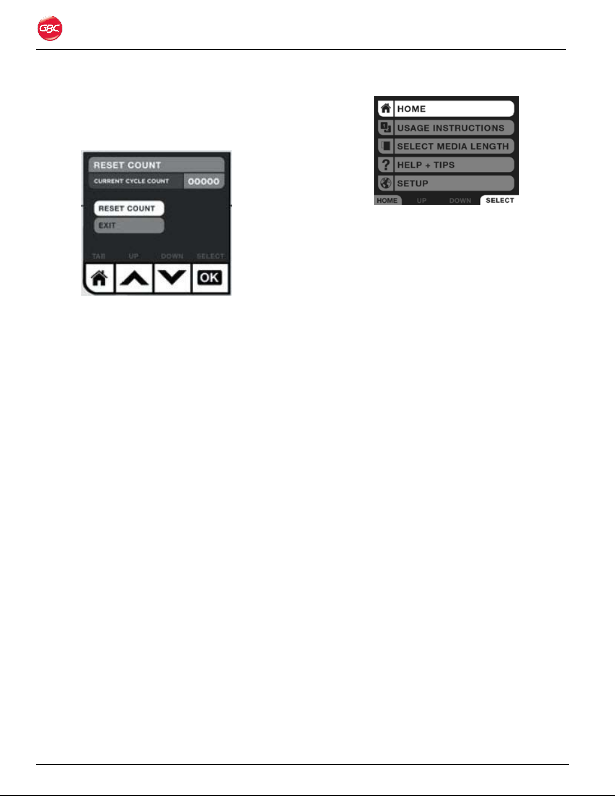
To reset the job cycles count:
On the Home screen, scroll to1. JOB CYCLES.
Press 2. SELECT.
Job Cycles Screen.Figure 16.
Scroll to 3. RESET COUNT.
Press 4. SELECT.
Press 5. HOME to return to the Status menu.
Die Indicator
The Die Indicator displays which Die Set is currently
in the Magnapunch 2.0. The Magnapunch 2.0 will
report one of the following errors if the Die Set was
not recognized, missing, or not properly inserted.
Magnapunch 2.0 – Installation and Operating Instructions
Menu Screen.Figure 17.
Navigate to any of the options by using UP and
DOWN. When the Menu option you would like to
choose is highlighted, press SELECT.
Home
Select HOME to return to the Home screen. See
“Home Screen”.
Usage Instructions
Select USAGE INSTRUCTIONS to go to that screen.
See “Usage Instructions”.
Select Media Length
Select SELECT STANDARD LENGTH to go to that
screen. See “Usage Instructions”.
Read error, punch operable• Somehow
layout Read error, punch operable = die is not
loaded properly but the system did not read
the bar code and recognize die pattern.
No die loaded, punch inoperable• No die
loaded, punch inoperable = die missing or not
loaded completely.
Refer to “Troubleshooting” for information on how to
resolve these issues.
Chip Drawer Status
The indicator displays how full the Chip Drawer is.
An ERROR is displayed when the drawer is nearly full
and needs to be emptied.
If the Chip Drawer is missing, the indicator displays
red circles as an error code.
Me n U
Use the Menu screen to access other key functions
of the Magnapunch 2.0. The Menu screen is
accessed from the Home screen. While on the
HOME screen, press MENU.
Help + Tips
Select HELP + TIPS to access Help screens. See
“Help + Tips”.
Setup
Select SETUP to go to the Setup screens. See “First
Time Setup”.
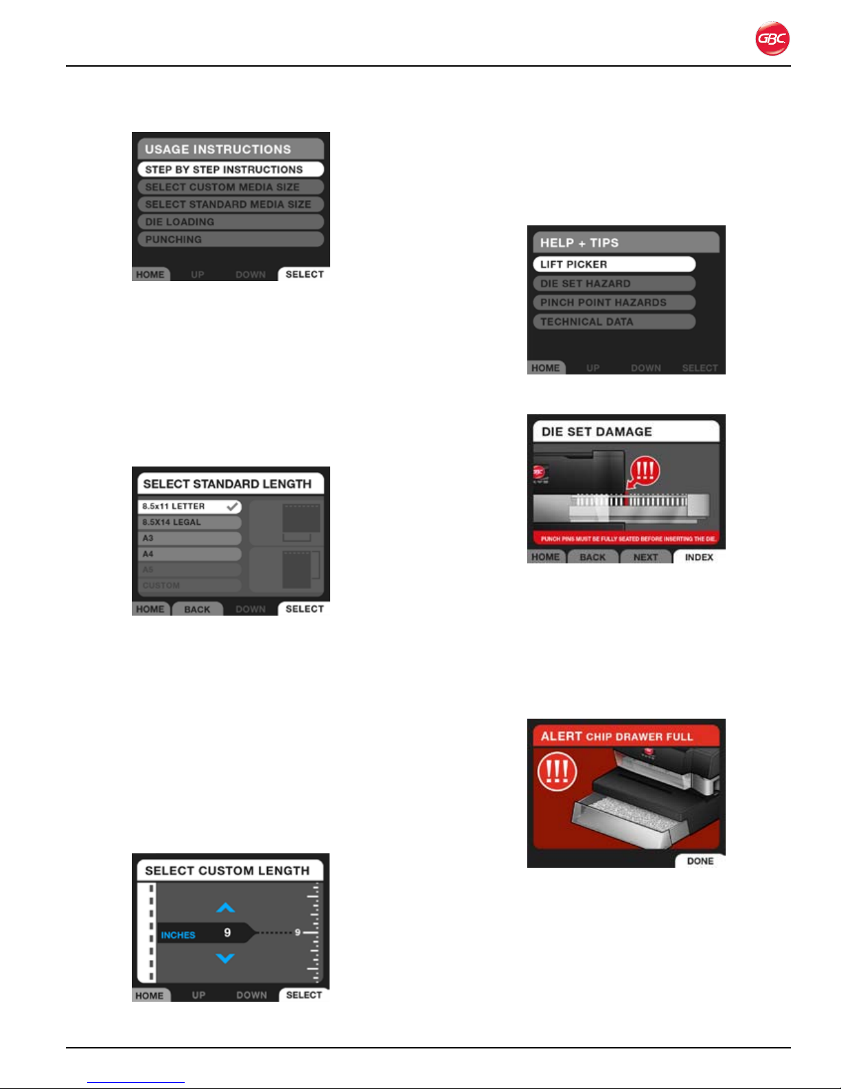
Us a G e in s t R U C t i o n s
Use the Usage Instructions screen to access
instructions on the operation and set up of the
Magnapunch 2.0. Some screens are animated and
self-explanatory, which show how to set up the
Magnapunch 2.0.
To access the Usage Instructions screen, press
MENU. Scroll to an option and press SELECT.
Page 6-4
Page 25
Magnapunch 2.0 – Installation and Operating Instructions
Usage Instructions Screen.Figure 18.
Step by Step Instructions
Selecting STEP BY STEP INSTRUCTIONS takes
you to the Select Standard Length screen.
Select Standard Length
Use the SELECT STANDARD LENGTH screen to
set the length of the media that will be punched.
he l p + ti p s
Use the HELP + TIPS screens to learn how to
operate the Magnapunch 2.0. Access this menu from
the MENU screen.
Help + Tips Menu.Figure 21.
Select Standard Length Screen.Figure 19.
Use UP and DOWN to highlight the media size to be
punched and then press SELECT. To return to this
screen or to select a different option, press LIST.
Custom
Use the Custom screen to set the Magnapunch 2.0
for other sizes of media. Select the size and then
use UP and DOWN to increase or decrease the size.
Briefly press and release UP and DOWN to scroll in
small increments and press and hold for to scroll in
large increments.
Die Set Damage Screen.Figure 22.
no t i f i C a t i o n sC R e e n s
Notification screens alert you to issues that may
prevent you from using the Magnapunch 2.0
properly. Follow the information on the screen to
rectify the issue. Also see “Troubleshooting”.
Example of an Alert Screen.Figure 23.
Select Custom Length Screen.Figure 20.
Page 6-5
Page 26
Magnapunch 2.0 – Installation and Operating Instructions
Ch a n G i n G t h e in t e R C h a n G e a B l e
die se t s
Your Magnapunch 2.0 offers the convenience
of interchangeable Die Sets, allowing you to
economically punch documents for a wide variety of
binding styles.
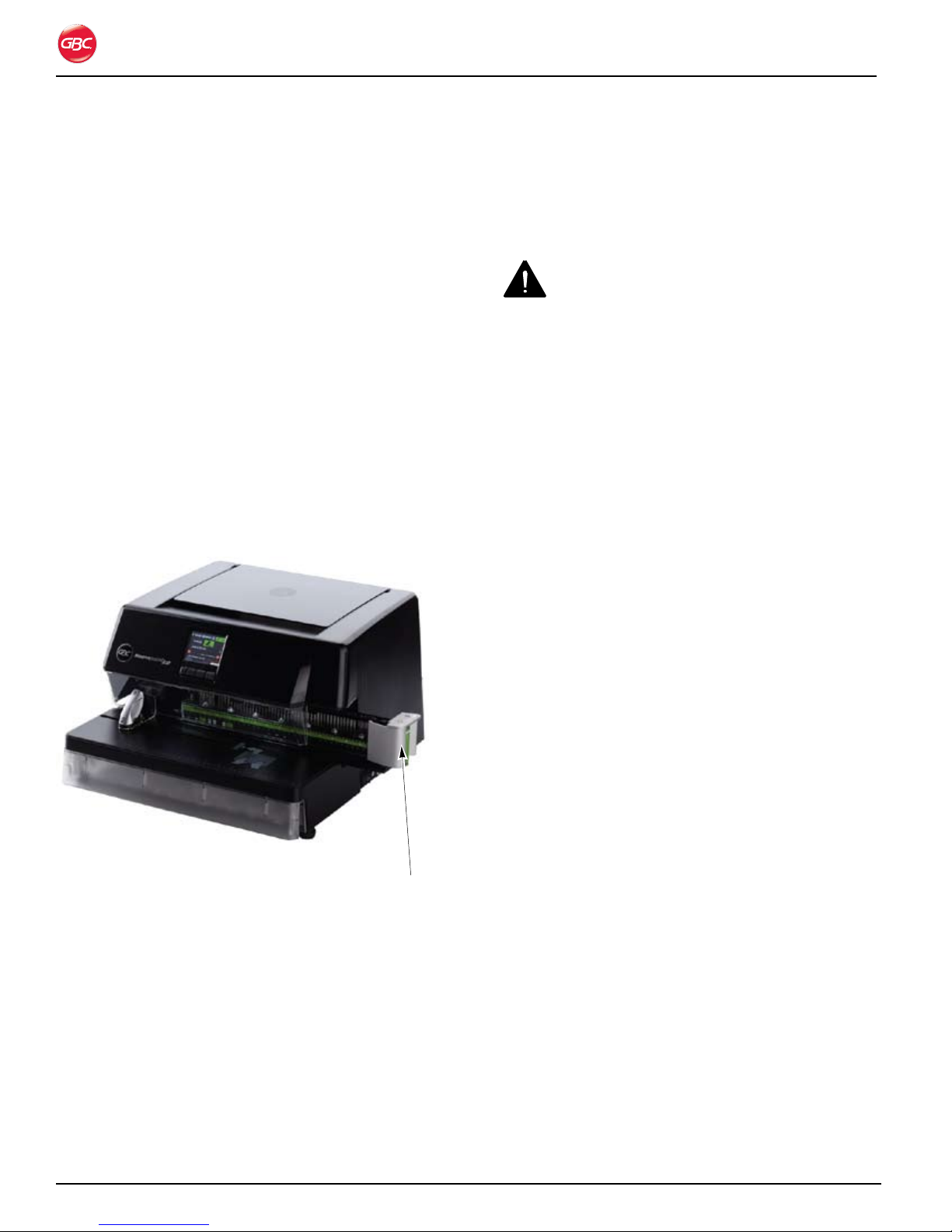
Re M o v i n G di e se t s
To remove Die Sets from the Magnapunch 2.0:
The interchangeable Die Set slot of the Magnapunch
2.0 is located on the right front side of the
Magnapunch 2.0. If a Die Set is already installed in
your Magnapunch 2.0, you can easily remove the Die
Set.
Grab the Die Set handle by placing your palm on 1.
the front and wrapping your fingers behind the
handle (located on the right side of the Die Set).
Die Set handle.
dust, and potential damage. Contact your GBC sales
representative for information on obtaining a Die Set
Storage Holder.
in s ta l l i n G di e se t s
CAUTIONS:
Possible pinch point hazard. When installing Die •
Sets into your Magnapunch 2.0, always keep
fingers and body parts out of the Magnapunch
2.0’s Die Set slot and away from all areas of the
Die Set except for the finger groove in the Die
Set’s handle. Failure to observe these precautions
may result in injury.
Possible Die Set damage. Make certain that all •
punch pins are fully and properly seated in the Die
Set before inserting the Die Set. Failure to ensure
that all punch pins are fully seated could result in
damage to the Die Set and Magnapunch 2.0.
To install a Die Set:
Grab the Die Set handle by placing your palm on 1.
the front and wrapping your fingers behind the
handle (located on the right side of the Die Set).
Refer to “Figure 24. Die Set Partially Pulled Out.”
Carefully align the leading edges of the Die 2.
Set’s support rails with the leading edges of the
Magnapunch 2.0’s guide rails.
Using your fingers in the Die Set’s handle, firmly 3.
push the Die Set into the Magnapunch 2.0’s Die
Set slot. You will hear a click when the automatic
locking mechanism engages. This mechanism
securely holds the Die Set during punching
operations.
Note: If the Die Set is not properly inserted into the
Magnapunch 2.0 and locked into place, the LCD
displays an error.
Die Set Partially Pulled Out.Figure 24.
Securely grasp the handle and tug firmly. 2.
Continue pulling on the handle until the Die Set 3.
is fully removed. Support the Die Set with both
hands.
Properly store the removed Die Set (away from 4.
dust, dirt, falls, etc.).
Helpful Hint: The GBC Die Set Storage Holder is
an excellent way to store your interchangeable Die
Sets for the Magnapunch 2.0. This holder securely
holds several Die Sets, protecting them from dirt,
Page 6-6
Page 27
Magnapunch 2.0 – Installation and Operating Instructions
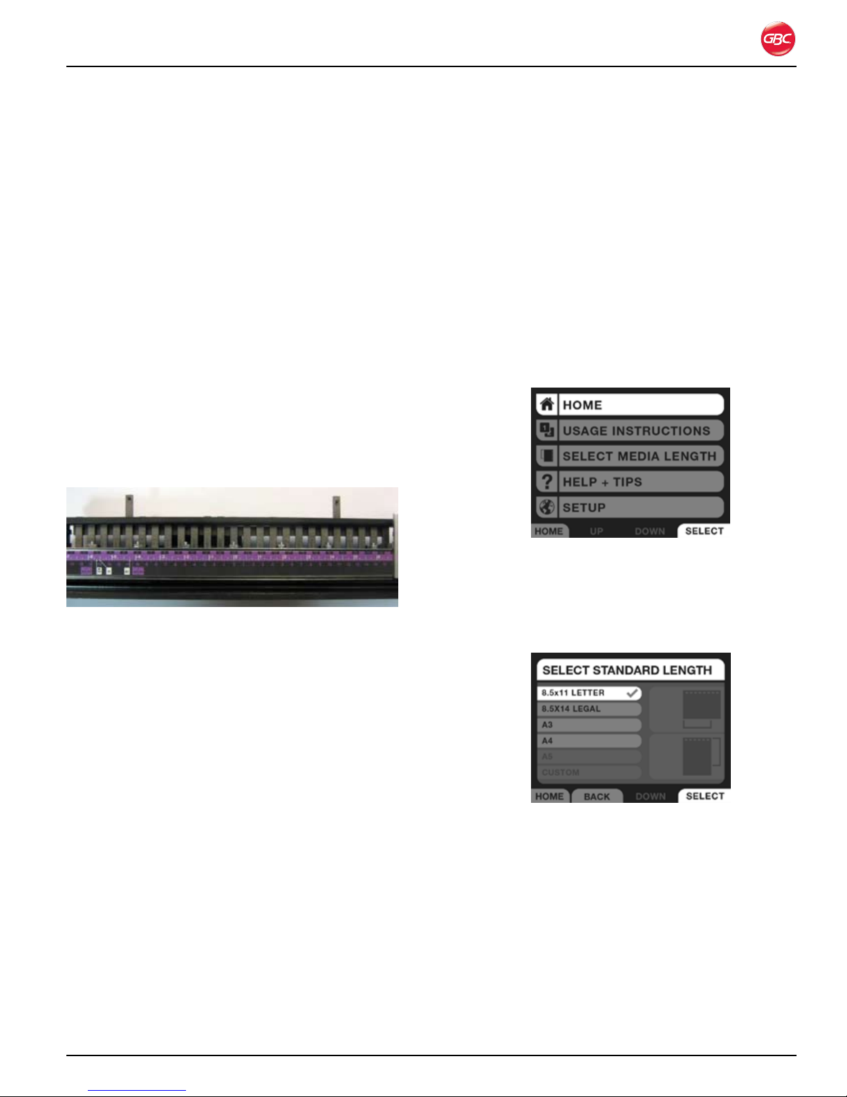
Re M o v i n G pU n C h pi n s
You can easily remove and replace punch pins
for proper punching some combinations of paper
sizes and punching patterns. The Magnapunch 2.0
helps you determine if and when punch pins need
to be removed. Refer to “Job Setup”, to set up the
Magnapunch 2.0. Each punch pin is labeled with a
number to help you identify the recommended pin to
be pulled.
NOTE: Each Die Set comes with a magnetic pin
retainer. Make sure this retainer is in place after
adjusting, removing, and inserting pins. Do not throw
this retainer away.
To remove punch pins:
Remove the magnetic Pin Retainer.1.
Firmly grasp the top of the selected Punch Pin 2.
and pull upward. The Punch Pin will slide out of
the Die Set.
Jo B se t U p
Before beginning a punching job, ensure the
Magnapunch 2.0 is setup properly. Use the LCD user
interface (UI) to guide you through the setup process.
For common paper sizes, use the marking on the Die
Set.
Us i n G t h e lCd Us e R in t e R f a C e
To set up the Magnapunch 2.0 for a job:
Insert the proper Die Set for the punch pattern 1.
required for the job. See “Punching Operation”.
Press 2. MENU on the Home screen.
Removing Punch Pins.Figure 25.
Carefully store the removed Punch Pin(s) for 3.
future use.
Replace the magnetic Pin Retainer.4.
To replace punch pins:
Remove the magnetic Pin Retainer.1.
Insert the Pins into the correct holes.2.
Replace the magnetic Pin Retainer.3.
Home Screen.Figure 26.
Scroll down and select 3. SELECT MEDIA
LENGTH.
Select one of the standard paper sizes or enter a 4.
custom paper size based on your application.
Select Standard Length ScreenFigure 27.
5.
Page 6-7
Page 28
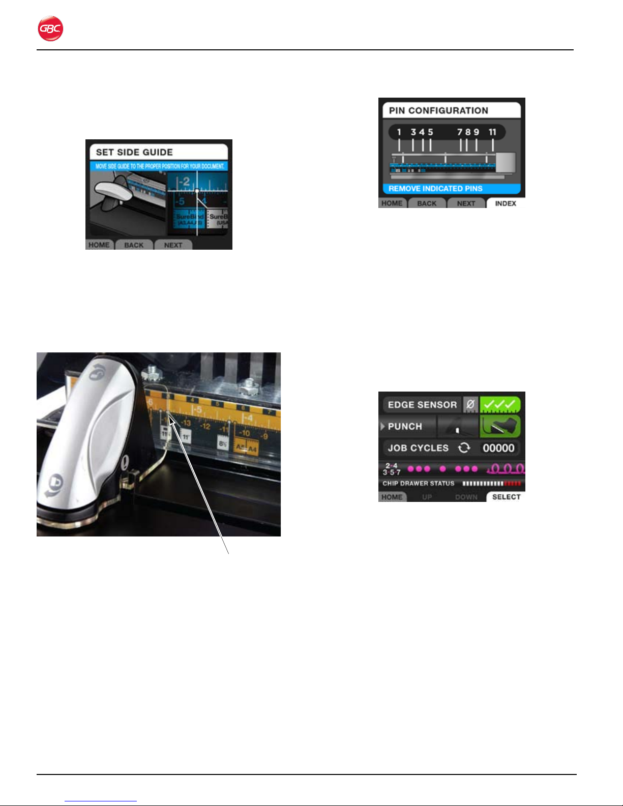
Press 6. NEXT. The LCD screen displays an image
similar to the ruler on the Die Set and shows
where the left Edge Guide should be placed.
Magnapunch 2.0 – Installation and Operating Instructions
Pin Configuration Screen.Figure 30.
Reinsert the Die Set into the Magnapunch 2.0.9.
Set Side Screen.Figure 28.
Slide the left Edge Guide to that position and 7.
press NEXT.
NOTE: When positioning the left Edge Guide, the
right edge of the clear pointer should be placed on
the dot.
Pointer on dot.
Setting Edge Guide On the Dot.Figure 29.
Following the instructions on the LCD UI, remove 8.
the Die Set from the Magnapunch 2.0, ensure
all pins are in place and then remove the pins
identified on the LCD UI. This will eliminate
punches at the edge of your document.
NOTE: Each pin is labeled with a pin number on the
Die Set ruler.
To leverage Die Set markings for common paper
sizes:
Common media sizes are displayed on the Die Set
label and have a line with a dot at the end identifying
where to set the left Edge Guide.
Insert the proper Die Set for the punch pattern 1.
required for the job.
On the 2. HOME screen, set the PUNCH mode to
foot pedal to avoid accidently cycling the punch.
Home Screen with Foot Pedal Selected.Figure 31.
Slide the left Edge Guide to the proper position 3.
based on your media size.
NOTE: when positioning the left Edge Guide, the
right edge of the clear pointer should be placed on
the dot. See “Figure 29. Setting Edge Guide On the
Dot.”
Insert your media to be punched and place 4.
against the left Edge Guide. Look at the Die Set
pins and identify any that need to be removed to
avoid punching the edge of your document.
Remove the Die Set and take out the pins if 5.
necessary.
Reinsert the Die Set.6.
Set the Punch mode back to 7. Trigger if needed.
Page 6-8
Sheet Sizes Larger Than the Maximum
Punch Width
Page 29
Magnapunch 2.0 – Installation and Operating Instructions
Because of its open-end Punch Throat design, you
can use your Magnapunch 2.0 to punch sheet sizes
that are larger than the maximum width of paper that
can be punched in one operation.
Note: Multiple steps are required to punch these
larger sheets of paper. Some experimentation will
be required to determine the correct position for the
Edge Guide.
te s t i n G t h e Jo B
Before beginning a punching job, test your
Magnapunch 2.0’s variable settings by punching
five to ten sheets of paper that match the exact size
of the actual materials to be bound. This will allow
you to make any adjustments to the Magnapunch
2.0 without wasting the documents to be bound.
The following steps indicate how to test your
Magnapunch 2.0 for proper Edge Guide alignment.
To test hole alignment for your job:
On the 1. HOME screen, set the PUNCH mode to
Foot Pedal to avoid accidently cycling the punch.
greater on the left, move the Edge Guide
to the right. Then punch another five test
sheets and re-check the spacings. Repeat
this process as needed until the spacings
are equal.
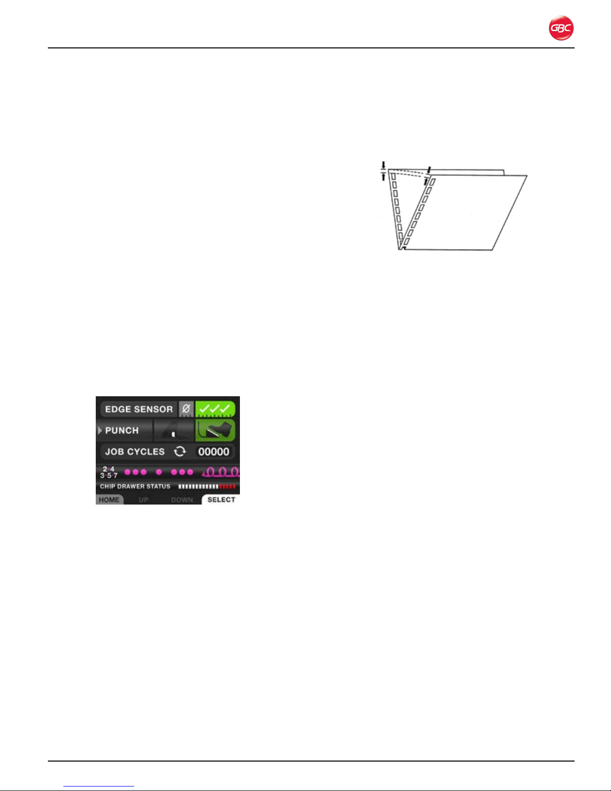
Checking Edge Guide Alignment.Figure 33.
For SureBind: b. Remove the punched sheets
from the Punch Throat. Fold the media
in half as represented in Figure 33. Look
at the two holes closest to the center or
“V” of the fold. The holes on each side
should line up with each other if the Edge
Guide is positioned properly. If this is not
correct, slightly adjust the Edge Guide,
punch another two to three test sheets, and
re-check the spacings. Repeat this process
as needed until the spacings are correct.
Note: Before making any adjustments to the
Magnapunch 2.0’s variable settings, make sure the
PUNCH mode on the HOME screen is set to Foot
Pedal to prevent accidently cycling the punch.
Home Screen with Foot Pedal Selected.Figure 32.
Insert five pieces of paper of the same size as 1.
the document to be punched completely into the
Punching Throat.
Slide the paper to the left until it touches the 2.
Edge Guide.
Hold the test sheets in place and depress the 3.
Foot Pedal to punch the test sheets.
To check the Edge Guide alignment, do one of 4.
the following.
For all punching patterns a. except SureBind:
Remove the punched sheets from the
Punch Throat. Take one punched sheet,
fold it so that the holes overlap, and confirm
the space between the edge of the media
and the first hole is equal to the space
between the edge of the media and the last
hole. If the spaces are not equal, slightly
adjust the Edge Guide. If the margin is
Page 6-9
Page 30
Magnapunch 2.0 – Installation and Operating Instructions
pU n C h i n G op e R a t i o n
pU n C h i n G t h e Jo B
Note: Before making any adjustments to the
Magnapunch 2.0’s variable settings, make sure the
PUNCH mode on the HOME screen is set to Foot
Pedal to prevent accidently cycling the punch.
After installing the correct Die Set in your
Magnapunch 2.0, and following the setup
instructions in “Job Setup” and “Testing the Job”, you
are ready to begin punching. The following sections
indicate how to activate the Magnapunch 2.0. Read
these sections completely to become familiar with
unique Die Set features and helpful punching tips.
Note: The Punching Margin is fixed for most Die Sets
and no margin adjustments are required. Refer to the
next section to set up the CombBinding Die with the
three position adjustable back gauge.
For CombBinding Only
The CombBind Die Set is equipped with a variable
punching margin (also called depth of punch)
device. This feature allows you to choose from three
punching margins for your plastic comb bound
documents. The punching margins offered by your
Magnapunch 2.0 are listed in the following table.
To change the punching margin for plastic
binding Die Sets:
Do one of the following.1.
For Punching Margin 3, firmly grasp the •
Control Lever and fully push it in to the Die
Set. The Control Lever will click into place
when this setting is reached.
For Punching Margin Setting 2, firmly grasp •
the Control Lever and pull gently outward.
The Control Lever will click into place as this
position is reached.
For Punching Margin Setting 1, continue to •
pull gently outward. The Control Lever will
click into place when this position is reached.
Punching Margin SettingsTable 2.
Punching
Margin
Setting
1 (Small) 0.10 in. (2.5 mm) ≤ 5/16 in. (7.9 mm)
2 (Medium) 0.14 in. (3.6 mm) 3/8 to 9/16 in. (9.5
3 (Large) 0.19 in. (4.8 mm) ≥ 5/8 in. (15.9 mm)
The Control Lever for setting the punching margin is
located inside of the plastic binding Die Set’s handle.
The punching margin is controlled by pushing in or
pulling out this lever.
Punching
Margin Depth
Best Plastic
Binding Elements
Diameter:
mm to 14.3 mm)
Die Set Partially Pulled Out. Figure 34.
Page 6-10
Page 31

Magnapunch 2.0 – Installation and Operating Instructions
pU n C h aC t i v a t i o n
The Magnapunch 2.0 can be activated using either
the Foot Pedal or the Tabletop Trigger. The activation
mode is selected on the HOME screen. Using
SELECT, toggle between the modes. The mode
highlighted in green is the active punch mode.
Home Screen with Foot Pedal Selected.Figure 35.
fo o t pe d a l
Using the Foot Pedal allows you to ensure that the
sheets are lined up before the punch is activated.
To punch using the Foot Pedal:
ta B l e t o p tR i G G e R
The Tabletop Trigger allows you to quickly punch
stacks of sheets. Pressing the stack against the
Trigger, activates the punch.
To punch using the Tabletop Trigger:
Turn the Magnapunch 2.0 On and set the 1.
PUNCH mode to TABLETOP TRIGGER.
Push the stack of sheets into the Punch Throat 2.
completely.
Turn the Magnapunch 2.0 On and set the 1.
PUNCH mode to FOOT PEDAL.
Push the stack of media into the Punch Throat 2.
completely, while sliding to the left, so that the
stack presses against the Edge Guide.
Media Lined up for Punching.Figure 36.
Media Ready for Punching.Figure 37.
Slide the stack to the left into the Tabletop 3.
Trigger, activating the punch.
Depress and then release the Foot Pedal.3.
Remove the stack of media.4.
Page 6-11
Page 32

Magnapunch 2.0 – Installation and Operating Instructions
pU n C h i n G ti p s
This section provides additional information about
punching paper and proper operation of the
Magnapunch 2.0.
pa p e R
The Magnapunch 2.0 is capable of punching any
paper from onion skin bond to cardboard stock.
Because there are variations in the thicknesses and
types of materials that can be punched, it is difficult
to define the exact maximum number of sheets that
can be punched at one time.
For typical maximum punching capacities for the
Magnapunch 2.0 using 20 lb. (75 g/m2) bond sheets,
refer to “Table 3. Punching Capacity”.
Punching too many sheets at a time can damage
the Magnapunch 2.0. It also affects the quality of the
punched holes. This hole quality degradation varies
by the paper stock and personal esthetic standards.
Generally, reducing the number of sheets punched
per cycle improves the quality and appearance of the
holes.
pl a s t i C Co v e R s
You can use the Magnapunch 2.0 to punch plastic
covers. Be sure to observe the following guidelines
to prevent damage to the Magnapunch 2.0 and Die
Sets.
Punch no more than two or three covers per •
cycle.
Separate each plastic cover with a sheet of 20 •
lb. (75 g/m2) paper before punching.
Ch i p dR a W e R
The Chip drawer is located at the front of the
Magnapunch 2.0 base. The Chip Drawer should be
periodically emptied to avoid jamming and damage
to the Magnapunch 2.0 and Die Sets.
Page 6-12
Chip Drawer Opened.Figure 38.
Page 33

Magnapunch 2.0 – Installation and Operating Instructions
ho l e QU a l i t y
The following table is a guide to help you determine
how many sheets of paper you can punch in each
cycle. This is based on 20 lb. (75 g/m2) bond.
Punching CapacityTable 3.
Die Label Die
Pattern
Color Coil 4:1
(0.2475)
Color Coil 4:1 (0.25)
Color Coil 4:1
(0.2475)
Color Coil 5:1
CombBind® 19-hole
ZipBind
WireBind 3:1
WireBind 2:1
WireBind 3:1
WireBind 2:1
ProClick® 3:1
VeloBind 11- pin
SureBind 10-pin
Looseleaf 3-5-7/
combo 2-4
®
Description Draft
Ensures that punched holes do not
overrun top and bottom of page
Industry standard 29 25 20
Oversized oval holes for spines over 20
mm; required for DigiCoil
— 29 25 20
Three position adjustable back gauge 39 32 25
Square punch pattern 29 25 20
Square punch pattern 34 25 20
Round punch pattern 34 25 20
Round punch pattern 34 25 20
For use with ProClick™ Pronto binding
systems
— 49 42 35
— 49 42 35
For punching U.S. letter size, A4 and
the 8.5 in. edge of legal and medical
documents
Good
Quality
29 25 20
24 14 14
24 20 16
34 30 25
Quality
Professional
Quality
Page 6-13
Page 34

Magnapunch 2.0 – Installation and Operating Instructions
Page 6-14
Page 35

Magnapunch 2.0 – Installation and Operating Instructions
7. op e R a t o R Ma i n t e n a n C e
Ca R i n G f o R t h e Ma G n a p U n C h 2.0
The primary maintenance required by the operator
is to periodically empty the Chip Drawer and to keep
the work area clean and free of paper debris and
dust. The Edge Sensors within the Die Sets may
need to be replaced occasionally.
die se t Ma i n t e n a n C e
The Edge Sensor feature referred to in “Edge
Sensor” requires sensor flags to be installed in the
Die Sets. If the machine begins to not sense the
media being inserted in the throat, the sensor flags
may need to be changed. Please follow the steps
below to replace the sensors.
To replace Die Set Edge Detection sensor flags:
Grab the die set handle by placing your palm on 1.
the front and wrapping your fingers behind the
handle. Pull the Die Set out of the Magnapunch
2.0 and place it face down on a sturdy surface.
Using a Phillips screw driver, remove the screws 2.
holding the two sensor flags in place.
Pull out the old sensor flags and replace with 3.
new ones.
Reinsert the screws and tighten4.
Replace the Die Set in the Magnapunch 2.0.5.
Cl e a n i n G t h e Ma G n a p U n C h 2.0
Clean only the exterior of the Magnapunch
2.0. A soft, damp cloth may be used to wipe
the Magnapunch 2.0’s exterior, but do not
use detergents or solvents as damage to the
Magnapunch 2.0 may occur.
WARNINGS:
Do not attempt to service or repair the •
Magnapunch 2.0.
Do not open the Magnapunch 2.0. There are no •
user serviceable parts inside.
Refer service to qualified service personnel.•
Failure to observe these warnings could result in
severe personal injury or death.
Page 7-1
Page 36

Magnapunch 2.0 – Installation and Operating Instructions
tR o U B l e s h o o t i n G
Symptom Possible Cause Corrective Action
Read error, punch is
operable
The barcode on the Die Set was not read
successfully.
The bar code reader is malfunctioning Contact your service provider.
Remove and reinsert the Die Set.
No Die Set loaded, punch
does not operate
One or both Edge
Detection sensors remain
on.
No power. Power cord not fully inserted. Check the power cord to ensure it is
Die Set is not fully inserted. Remove and re-insert the Die Set.
Die Set is not contacting the safety
switch.
Edge detection flag on Die Set is stuck in
an outward position.
Sensor could be blocked by paper dust. Remove Die Set and blow air into the
Faulty sensor. Contact your service provider.
Contact your service provider.
Remove Die Set and push the edge
detection flag in. If problem continues,
replace the flag.
area where the Die Set goes in the
Magnapunch 2.0.
connected fully at both ends.
If this does not resolve the problem,
contact your service provider.
Page 7-2
Page 37

Magnapunch 2.0 – Installation and Operating Instructions
no t e s
Date purchased:
Serial number:
Page 7-3
Page 38

Page 39

Page 40

ACCO Br ands Can ada
5 Precidio Cour t
Brampton, ON L6S-6B7
800.263.1063
www.gbccanada.com
ACCO Mexicana
Neptu no #43, Colo nia Nueva I ndustr ial Vallejo
Delagacion Gus tavo A. Madero, CP 07700
México, DF. (55) 1500-5578
www.gbc.com.mx
© 2011 ACCO Brands. All rights reserved. ACC O® is a regis tered trademark of
ACCO Br ands. GBC ® is a registered trad emark of General Bi nding Cor porati on.
Doc 80120510 Rev. A 11-2011
Page 41

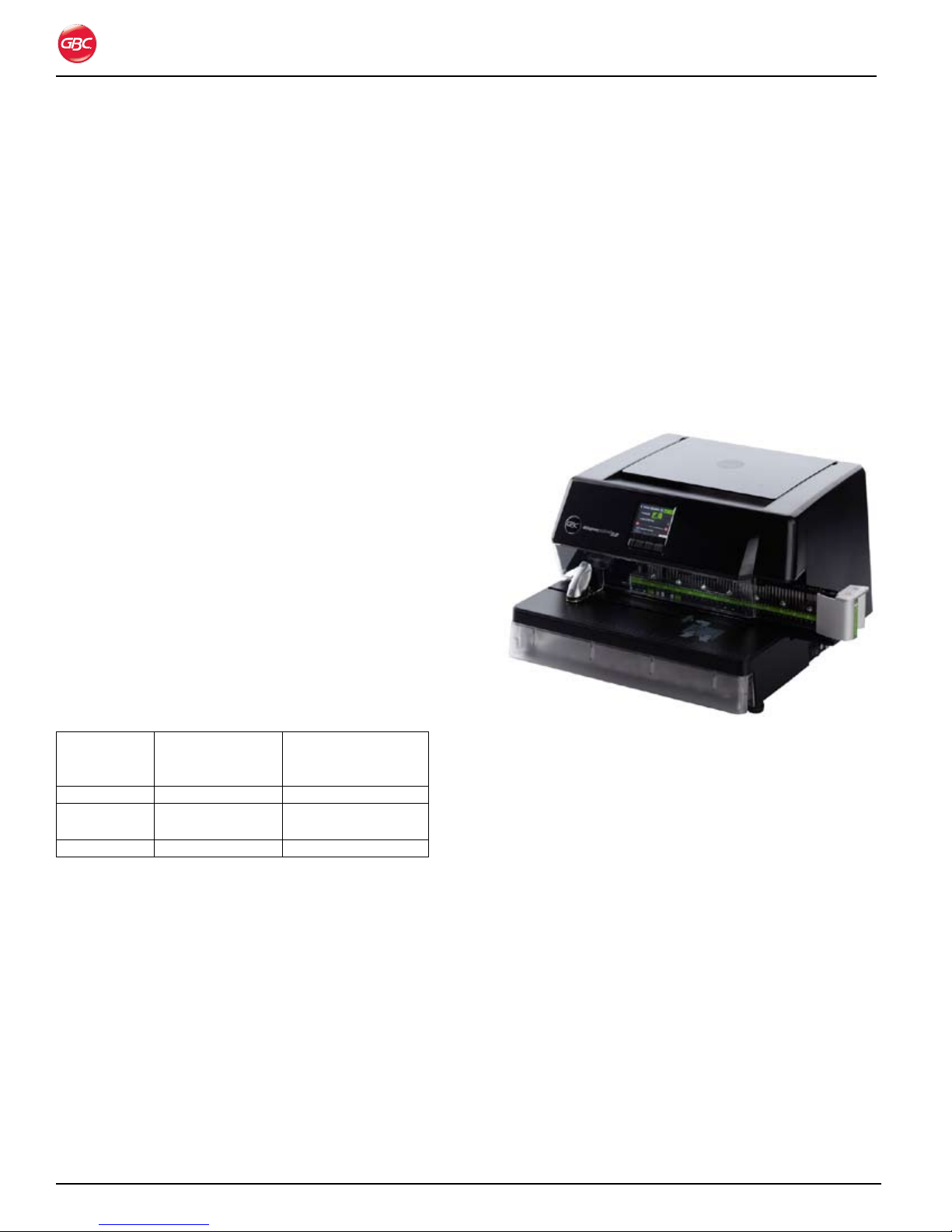
Magnapunch 2.0
Perforadora de gran capacidad
MANUAL DE INSTALACIÓN Y
FUNCIONAMIENTO
Está prohibido realizar copias sin el permiso por escrito de ACCO Brands.
Documento número: 80120510 Rev. A
Page 42

Magnapunch 2.0: Instrucciones de instalación y funcionamiento
ACCO Brands se reserva el derecho de realizar
modificaciones a esta publicación y a los productos
que aquí se describen sin previo aviso. Todas las
especificaciones y la información sobre los productos
están sujetas a cambio sin previo aviso. Las referencias
a información o productos protegidos por patentes o
derechos de autor que se realizan en esta publicación no
representan una licencia de acuerdo con los derechos
de ACCO Brands o de terceros. ACCO Brands no se
responsabiliza por las violaciones de patentes ni de
cualquier otro derecho de terceros.
Esta publicación está protegida por leyes de derechos
de autor © 2011 por ACCO Brands. Todos los derechos
reservados.
Co n v e n C i o n e s u t i l i z a d a s e n e s t e
m a n u a l
La perforadora Magnapunch 2.0 se maneja por medio de
un menú a través de una interfaz de usuario en LCD. Las
opciones del menú y los comandos aparecen en negrita.
Por ejemplo:
En el menú Language Setup (Configuración de idioma),
presione UP (Arriba) o DOWN (Abajo) para ir al idioma
deseado.
ACCO Br ands Can ada
5 Precidio Cour t
Brampton, ON L6S-6B7
800.263.1063
www.gbccanada.com
Página i
ACCO Mexicana
Neptu no #43, Colo nia Nueva I ndustr ial Vallejo
Delagacion Gus tavo A. Madero, CP 07700
México, DF. (55) 1500-5578
www.gbc.com.mx
© 2011 ACCO Brands. Todos los derechos reservad os. ACCO® e s una marca comercial regist rada
de ACCO Bra nds. GBC® e s una marca comercial regist rada de General Binding Corp oration.
80120510 Rev. A 11-2011
Page 43

Magnapunch 2.0: Instrucciones de instalación y funcionamiento
Ta b l a d e c o n T e n i d o s
1. Seguridad 1-1
Medidas de seguridad generales ...........................1-1
Precauciones para los juegos de matrices ........1-2
Energía eléctrica ......................................................1-2
Solo para máquinas que funcionan a
230 voltios .........................................................1-2
Servicio técnico de GBC ........................................ 1-3
Ubicaciones de la etiqueta de seguridad .............. 1-4
2. Garantía 2-1
Garantía limitada de 90 días ...................................2-1
3. Especificaciones 3-1
Dimensiones de las perforaciones .................... 3-2
Aviso de FCC clase A ............................................. 3-3
Aviso de Clase A para Canadá:
Avis Canada, Classe A ......................................... 3-3
Modificaciones ....................................................... 3-3
4. Instalación 4-1
Servicio técnico de GBC ........................................ 4-1
Antes de realizar la instalación .............................. 4-1
Instalación .............................................................. 4-1
Prueba ................................................................ 4-2
5. Guía de funciones 5-1
Energía eléctrica ..................................................... 5-1
Interruptor ON/OFF (Encendido/Apagado) ........ 5-1
Fusible ................................................................ 5-1
Conectores de la energía eléctrica y
del pedal. ......................................................... 5-1
Boca de perforación .............................................. 5-1
Bandeja para almacenar hojas .............................. 5-2
Interfaz de usuario ................................................. 5-2
LCD .................................................................... 5-2
Botones .............................................................. 5-2
Guía de papel y Activador de tablero .................... 5-2
Guía de papel ..................................................... 5-2
Activador de tablero .......................................... 5-3
Tablero de perforación ........................................... 5-3
Cajón de residuos .............................................. 5-3
Juego de matrices ............................................. 5-3
Pedal .................................................................. 5-3
Pantallas de notificación .................................... 6-6
Cómo cambiar los juegos de matrices
intercambiables ......................................................6-6
Cómo extraer los juegos de matrices................ 6-6
Cómo colocar los juegos de matrices ............... 6-6
Cómo extraer los punzones ............................... 6-7
Configuración de la tarea ....................................... 6-7
Cómo utilizar la interfaz de usuario de la
pantalla LCD .................................................... 6-7
Cómo probar la tarea ......................................... 6-9
Proceso de perforación ........................................6-10
Tarea de perforación .........................................6-10
Activación de la perforadora .................................6-11
Pedal .................................................................6-11
Activador de tablero .........................................6-11
Consejos para la perforación ...............................6-12
Papel .................................................................6-12
Cubiertas de plástico ........................................6 -12
Cajón de residuos .............................................6-12
Calidad de los orificios ..........................................6-13
7. Mantenimiento del operador 7-1
Cómo mantener la perforadora Magnapunch 2.0 ..7-1
Mantenimiento del juego de matrices ..............7-1
Cómo limpiar Magnapunch 2.0 ..........................7-1
Solución de problemas ...........................................7-2
Notas 7-3
6. Funcionamiento 6-1
Interfaz de usuario ................................................. 6-2
Navegación ........................................................ 6-2
Configuración inicial .......................................... 6-2
Funcionamiento ...................................................... 6-3
Pantalla Home (Principal) ................................... 6-3
Menú .................................................................. 6-4
Instrucciones de uso ......................................... 6-5
Ayuda y Consejos .............................................. 6-5
Página ii
Page 44

Magnapunch 2.0: Instrucciones de instalación y funcionamiento
Página iii
Page 45

Magnapunch 2.0: Instrucciones de instalación y funcionamiento
1. se g u R i d a d
Su seguridad y la de otras personas es muy importante.
Antes de instalar o utilizar Magnapunch 2.0, debe leer
detenidamente y respetar todos los avisos de seguridad de
este capítulo. Encontrará avisos de seguridad importantes
sobre Magnapunch 2.0 en este manual de instrucciones y
en el dispositivo. Lea todas las instrucciones y consérvelas
para consultarlas en el futuro.
Antes de los avisos de seguridad de este manual,
encontrará el símbolo de alerta de seguridad. Este símbolo
indica que puede existir un riesgo para su seguridad física
o la de otras personas.
Este símbolo de alerta de seguridad indica
que existe el riesgo de que se produzca una descarga
eléctrica. Le advierte que no debe abrir Magnapunch 2.0
ni exponerse a voltajes peligrosos.
Se pueden encontrar las siguientes advertencias en la
perforadora Magnapunch 2.0.
Este aviso de seguridad significa que puede resultar
gravemente herido o morir si abre Magnapunch 2.0 y se
expone al voltaje peligroso. No abra Magnapunch 2.0.
No contiene piezas que puedan ser reparadas por el
usuario. Las reparaciones las debe realizar el personal de
mantenimiento calificado.
Este aviso de seguridad significa
que la utilización de un fusible
inapropiado puede causar un
incendio o riesgo de descarga
eléctrica. Para mantener la
protección contra incendios o
riesgos de descarga eléctrica,
reemplace los fusibles con otros
del mismo tipo y valor nominal.
Si no respeta las advertencias, se pueden producir
lesiones físicas graves e incluso la muerte.
me d i d a s d e s e g u R i d a d g e n e R a l e s
adveRtenCias
No intente reparar ni realizar el mantenimiento de •
la perforadora Magnapunch 2.0.
No abra Magnapunch 2.0. No contiene piezas que •
puedan ser reparadas. Las reparaciones las debe
realizar el personal de mantenimiento calificado.
No conecte Magnapunch 2.0 a una fuente de •
alimentación de energía eléctrica para utilizarla
hasta que haya leído todas estas instrucciones.
Conserve estas instrucciones en una ubicación
conveniente para consultarlas en el futuro.
Para protegerse contra lesiones, siga las •
precauciones generales de seguridad cuando
instale y utilice la perforadora Magnapunch 2.0.
Asegúrese de que el interruptor de encendido se •
encuentre en la posición OFF (Apagado) cuando
Magnapunch 2.0 no esté en uso.
Revise que el área de trabajo no esté desordenada; •
de lo contrario, pueden producirse accidentes.
La perforadora Magnapunch 2.0 se debe colocar
sobre una superficie nivelada, firme y estable.
Deje suficiente espacio libre en la parte frontal y
posterior y a los costados de Magnapunch 2.0.
Mantenga el área de trabajo bien iluminada.
No utilice la perforadora Magnapunch 2.0 para •
otros fines que no sean para los que fue diseñada.
No fuerce ni retire los equipos de seguridad •
mecánicos y eléctricos como el mecanismo
de bloqueo, el revestimiento o la cubierta de
protección.
No introduzca objetos que no sean apropiados •
para perforar. No exponga el equipo a líquidos.
Utilice solo juegos de matrices intercambiables de •
GBC para Magnapunch 2.0 con esta perforadora.
Antes de utilizar Magnapunch 2.0, debe leer •
y comprender todo el contenido de estas
instrucciones.
Página 1-1
Page 46

Magnapunch 2.0: Instrucciones de instalación y funcionamiento
PR e C a u C i o n e s P a R a l o s j u e g o s d e
m a t R i C e s
PRECAUCIÓN:
Posible riesgo de punto de contacto. Cuando coloque •
los juegos de matrices en la perforadora, siempre
mantenga los dedos y otras partes del cuerpo fuera de
la ranura para los juegos de matrices de Magnapunch
2.0 y lejos de todas las áreas del juego de matrices
excepto por el asa del mango. Si no respeta estas
precauciones, se pueden producir lesiones.
Posibles daños del juego de matrices. Asegúrese de •
que todos los punzones se encuentren correctamente
colocados en el juego de matrices antes de colocarlo.
De lo contrario, se puede dañar el juego de matrices y
la perforadora Magnapunch 2.0.
en e R g í a e l é C t R i C a
La perforadora Magnapunch 2.0 solo debe conectarse
a una fuente de alimentación según se indica en estas
instrucciones y en la placa de nomenclatura ubicada en
la parte posterior de la máquina. Comuníquese con un
electricista en caso de que el enchufe proporcionado
con Magnapunch 2.0 no sea compatible con los
tomacorrientes del lugar.
ADVERTENCIA: No intente reparar ni realizar el
mantenimiento de Magnapunch 2.0. Si no respeta esta
advertencia, se pueden producir lesiones físicas graves e
incluso la muerte.
Asegúrese de que el interruptor de encendido se
encuentra en la posición Off (Apagado) cuando
Magnapunch 2.0 no esté en uso.
En caso de que le suceda lo siguiente, desconecte el
enchufe del tomacorriente y comuníquese con su proveedor o distribuidor, o con el Servicio técnico de GBC.
Si el cable de alimentación o el enchufe están •
dañados.
Si se volcó líquido sobre la perforadora •
Magnapunch 2.0.
Si Magnapunch 2.0 no funciona correctamente.•
Si la perforadora Magnapunch 2.0 no funciona •
como se describe en estas instrucciones.
PRECAUCIÓN: El tomacorriente debe estar
ubicado cerca de Magnapunch 2.0 y debe poder
acceder a él fácilmente.
Desconecte el enchufe del tomacorriente al que está
conectado y sostenga el cable de alimentación mientras
mueve Magnapunch 2.0.
so l o P a R a m á q u i n a s q u e f u n C i o n a n a
v o l t i o s
230
PRECAUCIÓN: Si utiliza Magnapunch 2.0 con
un cable de alimentación desmontable, siempre debe
controlar lo siguiente.
El cable consta de tres partes: el enchufe, el •
cable de alimentación y la conexión a la máquina.
Cada uno de estos componentes debe estar
homologado por las regulaciones de seguridad
europeas.
Por razones de seguridad, el cable de alimentación •
debe tener los siguientes valores mínimos de
energía eléctrica. No utilice cables que no cumplan
con los requisitos mínimos de energía eléctrica que
se indican a continuación.
Enchufe: 10 amperios, 250 voltios, 50/60 Hz,
homologado por las regulaciones de seguridad
europeas.
Cable de alimentación: Tipo HO5VV-F3G0.75,
armonizado (
indican que el cable de alimentación está homologado por las normas europeas correspondientes.
Nota: HAR equivale a la marca de homologación
de la agencia europea de seguridad que aprobó el
cable. Por ejemplo,
Conector de entrada de la perforadora: 10 amperios, 250 voltios, 50/60 Hz, homologado por las
regulaciones de seguridad europeas, tipo IEC 320.
El cable de alimentación no debe superar los 3
metros de longitud. Puede sustituir el cable de
alimentación por uno que tenga características
eléctricas superiores a las mínimas aquí
especificadas.
HAR ). Los símbolos
VDE .
Página 1-2
Page 47

Magnapunch 2.0: Instrucciones de instalación y funcionamiento
seRvi Ci o t é C n i C o d e gBC
Para solicitar accesorios de repuesto, mantenimiento,
piezas o un Acuerdo de Mantenimiento del Equipo,
comuníquese con el servicio técnico de GBC a la
siguiente dirección:
Estados Unidos
GBC Technical Service and Support – 3rd Floor
ACCO Brands
300 Tower Parkway
Lincolnshire, IL 60069
www.gbcconnect.com
1-800-723-4000
Canadá
ACCO Brands Canada
5 Precidio Court
Brampton, ON L6S-6B7
www.gbccanada.com
Callcentre@GBCCanada.com
1-800-463-2545
México
ACCO Mexicana
Neptuno #43, Colonia Nueva Industrial Vallejo
Delagacion Gustavo A. Madero, CP 07700
México, DF. (55) 1500-5578
www.accomexico.mx/index.php
(5525) 1500-5741
Otras fuentes
Para obtener información sobre el servicio técnico en
otras regiones, visite:
www.gbcconnect.com/contact_us.aspx
También puede utilizar su teléfono móvil para escanear el
código QR al costado de la perforadora Magnapunch 2.0 y
obtener una lista de proveedores de servicios autorizados.
Página 1-3
Page 48

Magnapunch 2.0: Instrucciones de instalación y funcionamiento
uBiCaCiones d e l a e t i q u e t a d e s e g u R i d a d
Ubicaciones de la etiqueta de seguridad de la perforadora Magnapunch 2.0.Figura 1.
Página 1-4
Page 49

Magnapunch 2.0: Instrucciones de instalación y funcionamiento
2. ga R a n t í a
ga R a n t í a l i m i t a d a d e 90 d í a s
ACCO Brands USA LLC, 300 Tower Parkway, Lincolnshire,
IL 60069 (en Canadá, ACCO Brands Canada Inc., 5
Precidio Court, Brampton, ON L6S-6B7; y en México,
ACCO Mexicana, S.A. de C.V. Av., Circuito Industrial
Norte #6 Parque Industrial Lerma 52000, Lerma Edo. De
México) (“ACCO Brands” respectivamente) garantiza al
comprador original que la perforadora Magnapunch 2.0,
producto de ACCO Brands, no tendrá defectos de material
ni de fabricación por el período de 90 días después de
la compra si se utiliza y se le realiza el mantenimiento en
condiciones normales.
La responsabilidad de ACCO Brands bajo esta garantía
se limita al reemplazo de piezas o la reparación, según
ACCO Brands estime conveniente, de cualquier parte
que presente defectos y que esté cubierta por la
garantía, sin cargo por materiales o mano de obra. Las
piezas pueden ser reemplazadas por el mismo producto
u otro producto similar que puede contener partes
restauradas o ensambladas nuevamente, según ACCO
Brands estime conveniente. Esta garantía será nula en
los siguientes casos:
(i) si el producto fue utilizado de manera inadecuada,
EN LA MEDIDA PERMITIDA POR LAS LEYES
CORRESPONDIENTES, ESTA GARANTÍA REEMPLAZA
A TODA OTRA GARANTÍA EXPRESA. NO ESTÁN
AUTORIZADAS LAS REPRESENTACIONES O
PROMESAS QUE NO SEAN COMPATIBLES CON
ESTA GARANTÍA O QUE SE AGREGUEN A ELLA;
Y NO GENERARÁN RESPONSABILIDADES PARA
ACCO BRANDS. EN LA MEDIDA PERMITIDA POR
LAS LEYES CORRESPONDIENTES, LA DURACIÓN
DE LAS GARANTÍAS IMPLÍCITAS (SI CORRESPONDE)
ESTÁ LIMITADA A LA DURACIÓN DE ESTA GARANTÍA.
ALGUNOS ESTADOS Y JURISDICCIONES NO PERMITEN
LIMITACIONES EN LA DURACIÓN DE UNA GARANTÍA
IMPLÍCITA. POR LO TANTO, ES POSIBLE QUE LA
LIMITACIÓN DESCRITA ANTERIORMENTE NO SE
APLIQUE EN SU CASO. EN LA MEDIDA PERMITIDA POR
LAS LEYES CORRESPONDIENTES, ACCO BRANDS
NO SERÁ RESPONSABLE EN ABSOLUTO DE LOS
DAÑOS Y PERJUICIOS ESPECIALES, ACCIDENTALES,
PUNITIVOS, INDIRECTOS O DE ÍNDOLE SIMILAR,
INDEPENDIENTEMENTE DE SU PREVISIBILIDAD.
EN ALGUNOS ESTADOS Y JURISDICCIONES NO SE
PERMITE LA EXCLUSIÓN O LIMITACIÓN DE DAÑOS Y
PERJUICIOS ESPECIALES, ACCIDENTALES, PUNITIVOS,
INDIRECTOS O DE ÍNDOLE SIMILAR, POR LO TANTO, ES
POSIBLE QUE LA LIMITACIÓN O EXCLUSIÓN DESCRITA
ANTERIORMENTE NO SE APLIQUE EN SU CASO.
(ii) si el producto presenta daños causados por
negligencia o accidente, o
(iii) si el producto ha sido modificado por cualquier
persona que no pertenezca a ACCO Brands o no sea
un agente autorizado de ACCO Brands.
Para ejecutar la garantía, comuníquese con ACCO Brands:
En los EE. UU.: 1-800-541-0094 o www.gbcconnect.com
En Canadá: 800-263-1063 o en www.gbccanada.com
En México: (55) 1500-5578 o www.gbc.com.mx
LOS CONSUMIDORES QUE GOZAN DE LOS BENEFICIOS
DE LAS LEYES Y REGULACIONES DE PROTECCIÓN
AL CONSUMIDOR EN LA JURISDICCIÓN DEL LUGAR
DE COMPRA, O EN SU DEFECTO, EN EL LUGAR DE
RESIDENCIA, TAMBIÉN POSEEN LOS BENEFICIOS
PROPORCIONADOS CON ESTA GARANTÍA ADEMÁS DE
LOS QUE LES BRINDAN LOS DERECHOS Y RECURSOS
DE LAS YA MENCIONADAS LEYES Y REGULACIONES DE
PROTECCIÓN AL CONSUMIDOR.
En la medida permitida por las leyes correspondientes,
esta garantía no se puede transferir y se cancelará
automáticamente si el comprador original del producto lo
vende o se desprende de éste de cualquier otra manera.
Esta garantía le proporciona derechos legales
específicos. Pueden existir otros derechos que
varían según la jurisdicción. Además de esto, algunas
jurisdicciones no permiten (i) la exclusión de ciertas
garantías, (ii) las limitaciones en la duración de una
garantía implícita o, (iii) la exclusión o limitación de
ciertos tipos de costos y daños o perjuicios. Por lo
tanto, es posible que no se apliquen las limitaciones
descritas anteriormente.
Página 2-1
Page 50

Magnapunch 2.0: Instrucciones de instalación y funcionamiento
Página 2-2
Page 51

Magnapunch 2.0: Instrucciones de instalación y funcionamiento
Width
Depth
Height
3. es P e C i f i C a C i o n e s
Artículo Especificación
Patrón de perforación
Encuadernación con anillas de plástico•
Espiral de color de plástico, GBC y •
estándar industrial 4:1 (C4)
Espiral de color de plástico, 5:1 (C5)•
Alambre doble cero, 2:1 (W2)•
Alambre doble cero, 3:1 (W3)•
VeloBind•
SureBind•
Encuadernación de 3 o 4 orificios•
Dimensiones
Ancho•
Alto•
Profundidad•
Peso
Máquina•
Envío•
Requisitos de suministro de energía
eléctrica
Fusible (F1 T1 A 250 V)•
Voltaje•
Corriente•
Energía eléctrica•
Tomacorriente de EE. UU.•
Nivel de ruido 94 dB cuando perfora la cantidad máxima de hojas del material.
Motor 1/4 HP
Capacidad de perforación: cantidad máxima de hojas con una densidad de
20 lb (75 g/m2).
39
29
29
29
34 (redondos) 29 (cuadrados)
34 (redondos) 29 (cuadrados)
49
49
34
18,5 in (47,0 cm)
12,0 in (30,5 cm)
20,0 in (50,8 cm)
94 lb (42,4 kg)
116 lb (52,6 kg)
Modelo de EE. UU.
20 A, 250 V
115 VAC
Máximo: 5,6 amperios, 50/60 Hz
644 W
NEMA 5-15R
Consulte la placa de nomenclatura
ubicada en la parte posterior de la
perforadora Magnapunch 2.0 para
ver los valores de energía eléctrica
específicos compatibles con la unidad.
De acuerdo con las directivas 2003/10/EC sobre los requisitos mínimos de
seguridad y salud con respecto a la exposición de los trabajadores a los riesgos
que generan los agentes físicos (ruido), los siguientes niveles de presión de ruido
requieren que los empleadores tomen las siguientes medidas:
80 dB: los empleadores deben proporcionar protección auditiva a los •
trabajadores.
85 dB: se debe colgar un aviso de advertencia sobre la protección auditiva. •
87 dB: los trabajadores deben utilizar protectores auditivos individuales.•
Modelo europeo
20 A, 250 V
230 VAC
Máximo: 3,5 amperios, 50/60 Hz
805 W
YP-24 R
Consulte la placa de nomenclatura
ubicada en la parte posterior de la
perforadora Magnapunch 2.0 para
ver los valores de energía eléctrica
específicos compatibles con la unidad.
Ancho
Alto
Profundidad
Referencia de las dimensionesFigura 2.
Página 3-1
Page 52

Magnapunch 2.0: Instrucciones de instalación y funcionamiento
di m e n s i o n e s d e l a s P e R f o R a C i o n e s
Patrón de perforación Longitud máxima de
perforación
Encuadernación con anillas de plástico 14 in (356 mm) 25 0,5625 in (14,29 mm)
Espiral de color de plástico, GBC 4:1 (C4) 14 in (356 mm) 55 0,2475 in (6.29 mm)
Espiral de color de plástico, estándar
industrial 4:1 (C4)
Espiral de color de plástico, 5:1 (C5) 14 in (356 mm) 69 0,20 in (12,70 mm)
Alambre doble cero, 2:1 (W2) 14 in (356 mm) 27 0,50 in (12,70 mm)
Alambre doble cero, 3:1 (W3) 14 in (356 mm) 41 0,3333 in (8,47 mm)
ProClick 3:1 cuadrado 12 in (305 mm) 34 0,3333 in (8,47 mm)
VeloBind
SureBind
Encuadernación de 3 o 4 orificios Variable Hasta 7 o 4 Variable
®
®
14 in (356 mm) 55 0,25 in (6,35 mm)
15 in (381 mm) 14 1,0 in (25,40 mm)
14 in (356 mm) 12 Variable
Cantidad de punzones Distancia entre los orificios
(de centro a centro)
Página 3-2
Page 53

Magnapunch 2.0: Instrucciones de instalación y funcionamiento
av i s o d e fCC C l a s e a
Este dispositivo cumple con lo dispuesto en la Sección 15
de las normas de la FCC. El funcionamiento depende de
las siguientes condiciones:
Este dispositivo no debe causar interferencia •
dañina.
Este dispositivo debe aceptar las interferencias •
recibidas, incluso aquellas que pueden causar un
mal funcionamiento.
Nota: Este equipo se ha probado y se considera que
cumple con los límites de un dispositivo digital de Clase
A, de acuerdo con la Sección 15 de las normas de la
FCC. Estos límites están diseñados para proporcionar
una protección razonable contra la interferencia dañina
cuando el equipo funciona en un entorno comercial.
Este dispositivo genera, utiliza y puede emitir ondas de
radiofrecuencia. Por lo tanto, si no se instala y no se
usa de acuerdo con el manual de instrucciones, puede
provocar interferencia dañina en las comunicaciones por
radio. El uso de este equipo en un área residencial puede
provocar interferencia dañina. En este caso, los gastos en
los que incurra el usuario para corregir las interferencias
correrán a su cargo.
mo d i f i C a C i o n e s
Toda modificación que se realice a este dispositivo y que
no sea autorizada por ACCO Brands anulará la autoridad
que la FCC y la industria de Canadá otorgó al usuario para
utilizar este dispositivo.
Toutes modifications apportées à ce dispositif et non
approuvées par ACCO Brands Corporation annuleront le
droit accordé à l’utilisateur par le FCC et/ou par Industrie
Canada de faire fonctionner cet équipement.
av i s o d e Cl a s e a P a R a Ca n a d á :
av i s Ca n a d a , Cl a s s e a
Este dispositivo digital de Clase A cumple con la norma
ICES-003 de Canadá.
Cet appareil numérique de la classe B est conforme à la
norme NMB-003 du Canada.
Página 3-3
Page 54

Magnapunch 2.0: Instrucciones de instalación y funcionamiento
Página 3-4
Page 55

Magnapunch 2.0: Instrucciones de instalación y funcionamiento
4. in s t a l a C i ó n
in s t a l a C i ó n
ADVERTENCIA: No intente reparar ni realizar el
mantenimiento de Magnapunch 2.0. Si no respeta esta
advertencia, se pueden producir lesiones físicas graves
e incluso la muerte.
En caso de que le suceda lo siguiente, desconecte el
enchufe del tomacorriente y comuníquese con el Servicio
técnico de GBC.
Para retirar Magnapunch 2.0 del embalaje:
Corte las tiras de plástico y la cinta adhesiva de 1.
embalaje.
Retire la perforadora Magnapunch 2.0 de la caja de 2.
embalaje. En los cortes en la base de cartón se indica
dónde debe colocar las manos.
Si el cable de alimentación o el enchufe están •
dañados.
Si se volcó líquido sobre la perforadora •
Magnapunch 2.0.
Si Magnapunch 2.0 no funciona correctamente.•
Si la perforadora Magnapunch 2.0 no funciona •
como se describe en estas instrucciones.
seRvi Ci o t é C n i C o d e gBC
Estados Unidos
1-800-723-4000
Canadá
1-800-463-2545
México
(5525) 1500-5741
Otras fuentes
Para obtener información sobre el servicio técnico en
otras regiones, visite:
www.gbcconnect.com/contact_us.aspx
También puede utilizar su teléfono móvil para escanear el
código QR al costado de la perforadora Magnapunch 2.0 y
obtener una lista de proveedores de servicios autorizados.
Para preparar la perforadora Magnapunch 2.0 por
primera vez:
Coloque Magnapunch 2.0 sobre una superficie 1.
plana, firme y estable capaz de soportar el peso de
la máquina. Se recomienda que haya una superficie
adicional cerca de Magnapunch 2.0 para colocar los
elementos que debe perforar.
Magnapunch 2.0 debe estar ubicada cerca de la 2.
fuente de alimentación y debe tener suficiente espacio
en la parte posterior y superior para que se ventile. Es
necesario que haya un espacio apropiado en la parte
superior de la perforadora para poder abrir la tapa y
colocar el papel a perforar.
Conecte el enchufe proporcionado con la perfora-3.
dora Magnapunch 2.0 solo a un tomacorriente
adecuadamente conectado a tierra. Evite conectar
otros dispositivos en la misma rama del circuito en la
que está conectada la perforadora Magnapunch 2.0;
de lo contrario, se puede activar el disyuntor y se
pueden quemar los fusibles.
Conecte el pedal a la parte posterior de la perforadora 4.
Magnapunch 2.0 y coloque el pedal sobre el suelo al
alcance del pie.
an t e s d e R e a l i z a R l a i n s t a l a C i ó n
Inspeccione el envoltorio y la perforadora Magnapunch
2.0 y controle que no estén dañados. Se debe notificar
inmediatamente al servicio de transporte en caso de que
se hayan dañado durante el envío.
Magnapunch 2.0 pesa 94 lb (42,4 kg). Son necesarias dos
personas para levantar y mover la perforadora.
Página 4-1
Page 56

Magnapunch 2.0: Instrucciones de instalación y funcionamiento
PR u e B a
Después de haber instalado correctamente la perforadora
Magnapunch 2.0, se debe realizar una prueba para
asegurarse de que funcione correctamente.
Notas:
La primera vez que se enciende la perforadora •
Magnapunch 2.0, aparece una pantalla de configuración. Seleccione el idioma y las unidades de
medición.
Pantalla Language Setup (Configuración de idioma).Figura 3.
Se debe instalar un juego de matrices antes •
de poner a la perforadora Magnapunch 2.0 en
funcionamiento.
Para probar la perforadora Magnapunch 2.0:
Perfore 10 hojas de papel con una densidad de 20 lb 1.
(75 g/m2) juntas.
Perfore cinco hojas de papel con una densidad de 20 lb 2.
(75 g/m2) y controle si se perforaron correctamente.
Si utiliza un juego de matrices PB, perfore 10 hojas 3.
de papel con una densidad de 20 lb (75 g/m2) con la
configuración de cada calibrador posterior y asegúrese de que se encuentre en tres posiciones distintas.
Página 4-2
Page 57

Magnapunch 2.0: Instrucciones de instalación y funcionamiento
5. gu í a d e f u n C i o n e s
Este capítulo le permitirá identificar los componentes principales de la perforadora Magnapunch 2.0.
Interfaz de usuario
Guía de papel y
Activador de tablero
Tablero de perforación
Cajón de residuos
Bandeja para
almacenar hojas
Juego de matrices
Fusible
Boca de perforación
Identificación de Magnapunch 2.0. Figura 4.
en e R g í a e l é C t R i C a
in t e R R u P t o R on/off (en C e n d i d o /
P a g a d o )
a
Utilice el interruptor ON/OFF (Encendido/Apagado) para
encender y apagar la perforadora Magnapunch 2.0. Lleve
el interruptor ON/OFF (Encendido/Apagado) hacia la
posición I para encender la perforadora Magnapunch 2.0.
Lleve el interruptor ON/OFF (Encendido/Apagado) hacia la
posición O para apagar la perforadora Magnapunch 2.0.
fu s i B l e
Un fusible protege a la perforadora Magnapunch 2.0 y a
los componentes eléctricos contra la corriente con valor
nominal mayor al de la máquina.
PRECAUCIÓN: Para mantener la protección contra
incendios o riesgos de descarga eléctrica, reemplace los
fusibles con otros del mismo tipo y valor nominal.
Para reemplazar un fusible, coloque un destornillador de
punta plana en la cubierta del fusible, empuje y después
gire hacia la izquierda. Cambie el fusible, coloque el
reemplazo en la base del fusible y gire hacia la derecha.
Interruptor ON/OFF
(Encendido/Apagado)
Co n e C t o R e s d e l a e n e R g í a e l é C t R i C a
y d e l P e d a l .
Energía eléctricaPedal Puerto de servicio
Conexiones en la parte posterior Figura 5.
de la perforadora Magnapunch 2.0.
El cable de alimentación se conecta a un tomacorriente
de pared 115 VAC NEMA 5-15R estándar para los EE. UU.
(230 VAC YP-24 europeo de 10 a 16 amperios).
Bo C a d e P e R f o R a C i ó n
La boca de perforación es el lugar en el que se introduce
el borde del material a perforar durante el proceso de
perforación.
NOTA: Si el material no ingresa fácilmente en la boca de
perforación, no lo fuerce.
Página 5-1
Page 58

Magnapunch 2.0: Instrucciones de instalación y funcionamiento
Ba n d e j a P a R a a l m a C e n a R h o j a s
Levante la tapa de la bandeja para almacenar hojas que se
han perforado o que se van a perforar.
Magnapunch 2.0 con hojas Figura 6.
en la bandeja para almacenarlas.
in t e R f a z d e u s u a R i o
La interfaz de usuario (UI) consta de una pantalla LCD y
cuatro botones ubicados debajo de la pantalla. La pantalla
LCD muestra los mensajes del sistema y permite acceder
a las funciones de la máquina. Los botones debajo de la
pantalla se utilizan para navegar los menús, seleccionar
opciones y ejecutar comandos.
Bo t o n e s
Los botones se relacionan con los comandos ubicados
en la parte inferior de la pantalla. La acción que realiza el
botón cambia de acuerdo con el menú que aparece en la
pantalla LCD.
gu í a d e P a P e l y aC t i v a d o R d e
t a B l e R o
Mango para ajustar
la guía de papel
Guía de papel y Activador de tablero.Figura 8.
gu í a d e P a P e l
La Guía de papel permite establecer la posición para una
gran variedad de patrones de perforación y tamaños de
papel.
Activador de tablero
Pantalla Start Up (Inicio).Figura 7.
lCd
La pantalla LCD muestra constantemente el estado de
Magnapunch 2.0 e incluye instrucciones detalladas para
usarla.
Página 5-2
Gire el mango de la Guía de papel 1/4 de vuelta hacia la
izquierda para destrabarla. Deslice la Guía de papel para
alinearla con la configuración deseada en el juego de
matrices y gire el mango hacia la derecha 1/4 de vuelta
para que la Guía de papel quede ajustada en su lugar.
Guía de papel sin trabar.Figura 9.
Page 59

Magnapunch 2.0: Instrucciones de instalación y funcionamiento
aC t i v a d o R d e t a B l e R o
El Activador de tablero está incorporado en la Guía de
papel. Se utiliza para perforar automáticamente sin usar
el pedal. El Activador de tablero se activa en la pantalla
Home (Principal) de la interfaz de usuario.
Coloque la resma de hojas en la boca de perforación y
luego deslícela hacia la izquierda contra el activador para
perforarla.
ta B l e R o d e P e R f o R a C i ó n
En el Tablero de perforación se coloca el material
a perforar. Coloque el material sobe el Tablero de
perforación, empújelo hacia la boca de perforación
y luego deslícelo hacia la izquierda.
Ca j ó n d e R e s i d u o s
El cajón de residuos recoge los restos del papel que se
ha perforado. Cuando el cajón de residuos está lleno,
aparecerá un mensaje en la pantalla LCD que le avisa que
debe vaciar el cajón.
ju e g o d e m a t R i C e s
Magnapunch 2.0 ofrece trece juegos de matrices distintos
para todos los requisitos de perforación para sus documentos. Para cambiar un juego de matrices, consulte
“Cómo cambiar los juegos de matrices intercambiables”.
Pe d a l
El interruptor del pedal se activa en la pantalla Home
(Principal). Cuando se coloca el material en la boca de
perforación y se empuja contra la guía de papel, debe
presionar el pedal para activar la perforadora.
Pedal.Figura 10.
Página 5-3
Page 60

Magnapunch 2.0: Instrucciones de instalación y funcionamiento
Página 5-4
Page 61

Magnapunch 2.0: Instrucciones de instalación y funcionamiento
6. fu n C i o n a m i e n t o
Magnapunch 2.0 utiliza una variedad de juegos de matrices fácilmente intercambiables para lograr distintos estilos de encuadernación. Si selecciona el juego de matrices apropiado, puede utilizar Magnapunch 2.0 para perforar documentos en cualquiera de
los estilos de encuadernación que se indican en la siguiente tabla:
Estilos de perforaciónTabla 1.
Margen mínimo para
Estilos de encuadernación Patrón de perforación
CombBind
Color Coil
Espiral de color
Espiral de color 5:1 (5 orificios por pulgada) 1 0,030 in (0,8 mm)
WireBind
WireBind
VeloBind 1 orificio por pulgada 0,500 in (12,7 mm)
SureBind
Encuadernación de 3, 5 ó 7
orificios en 11 in
Encuadernación de 2 ó 4
orificios para papel A4
®
®
®
®
Cerlox (Peine de plástico y encuadernación con anillas de plástico)
4:1 de GBC [4 orificios por pulgada con una distancia entre los
orificios (de centro a centro): 0,2475"]
Estándar industrial 4:1 [4 orificios por pulgada con una distancia
entre los orificios (de centro a centro): 0,2500"]
2:1 (2 orificios por pulgada) Se encuentran disponibles patrones de
orificios redondos y cuadrados.
3:1 (3 orificios por pulgada) Se encuentran disponibles patrones de
orificios redondos y cuadrados.
Aproximadamente 1 orificio por pulgada
3 orificios a lo largo del borde del documento, papel de 11 pulgadas
4 orificios a lo largo del borde del documento, papel A4
el primer orificio de
perforación
0,282 in (7,2 mm)
0,092 in (2,6 mm)
0,040 in (1,0 mm)
0,375 in (9,5 mm)
0,261 in (6,6 mm)
0,531 in (13,5 mm)
Nota: Para cada estilo de perforación indicado en la
tabla se debe utilizar un juego de matrices distinto en
Magnapunch 2.0. También se pueden elaborar juegos
de matrices personalizados para patrones especiales de
encuadernación (no se incluyen en la tabla) según sus
especificaciones. Para obtener más información sobre los
juegos de matrices personalizados, comuníquese con el
representante de ventas de GBC en su localidad.
IMPORTANTE: Cada juego de matrices intercambiables
posee una etiqueta adhesiva en el mango que indica
el patrón de perforación de ese juego. Cuando lea las
Instrucciones de funcionamiento, observe las instrucciones especiales para el patrón de perforación correcto
correspondiente al juego de matrices que haya instalado
en Magnapunch 2.0.
ADVERTENCIA: No intente reparar ni realizar el
mantenimiento de Magnapunch 2.0. Si no respeta esta
advertencia, se pueden producir lesiones físicas graves
e incluso la muerte.
En caso de que le suceda lo siguiente, desconecte el
enchufe del tomacorriente y llame a uno de los números
que se indican a continuación para comunicarse con su
proveedor o distribuidor, o con el Servicio técnico de GBC.
Si el cable de alimentación o el enchufe están •
dañados.
Si se volcó líquido sobre la perforadora •
Magnapunch 2.0.
Si Magnapunch 2.0 no funciona correctamente.•
Si la perforadora Magnapunch 2.0 no funciona •
como se describe en estas instrucciones.
EE. UU.: 800-723-4000
Canadá: 800-463-2545
México: (5525) 1500-5741
PRECAUCIÓN:
El tomacorriente debe estar ubicado cerca de •
Magnapunch 2.0 y debe poder acceder a él
fácilmente.
Desconecte el enchufe del tomacorriente al •
que está conectado y sostenga el cable de
alimentación mientras mueve Magnapunch 2.0.
No utilice la perforadora Magnapunch 2.0 para •
otros fines que no sean para los que fue diseñada.
No fuerce ni retire los equipos de seguridad •
mecánicos o eléctricos como el revestimiento
o la cubierta de protección.
No introduzca objetos que no sean apropiados •
para perforar. No exponga el equipo a líquidos.
Utilice solo juegos de matrices intercambiables de •
GBC para Magnapunch 2.0 con esta perforadora.
Si no respeta las advertencias, se pueden producir
lesiones físicas graves e incluso la muerte.
Página 6-1
Page 62

Magnapunch 2.0: Instrucciones de instalación y funcionamiento
in t e R f a z d e u s u a R i o
La pantalla LCD y la fila de botones ubicada debajo
conforman la interfaz de usuario (UI). La pantalla LCD
muestra el estado y las configuraciones actuales de
Magnapunch 2.0, y proporciona instrucciones de configuración y funcionamiento para usar Magnapunch 2.0.
na v e g a C i ó n
Utilice los botones en el teclado para navegar los menús,
desplazarse hacia arriba o abajo y seleccionar opciones. En
la pantalla LCD se indica la función que tienen los botones.
Cuando se enciende la perforadora Magnapunch 2.0, se
muestra brevemente la pantalla Start Up (Inicio) y después
sigue la pantalla Home (Principal).
LCD
Si Magnapunch 2.0 ha estado inactiva por más de 30
minutos, en la pantalla LCD aparece la pantalla Start Up
(Inicio) y entra en estado de suspensión. Para volver a
activar la pantalla, presione cualquier tecla.
Co n f i g u R a C i ó n i n i C i a l
La primera vez que inicie Magnapunch 2.0, deberá
configurar el idioma y la unidad de medida que se utilizará
en los menús. La pantalla Language Setup (configuración
de idioma) aparece después de la breve aparición de
la pantalla de inicio. Después de que haya realizado la
configuración, estas pantallas no volverán a aparecer.
Para acceder a ellas desde la pantalla Home (Principal)
en cualquier momento, seleccione MENU (Menú) desde
la pantalla Home (Principal) y luego seleccione la función
SETUP (Configuración) en las opciones del MENU (Menú).
Para configurar el idioma y las unidades:
Encienda Magnapunch 2.0.1.
Teclado
Interfaz de usuario y pantalla Home (Principal).Figura 11.
HOME (Principal) Permite regresar a la pantalla Home
(Principal).
UP (Arriba) Permite desplazarse hacia arriba
por las opciones.
Cuando la selección llega al
principio de la lista de opciones,
regresa al final.
BACK (Atrás) Permite regresar a la pantalla
anterior.
DOWN (Abajo) Permite desplazarse hacia abajo por
las opciones. Cuando la selección
llega al final de la lista de opciones,
regresa al principio.
NEXT (Siguiente) Permite pasar a la pantalla siguiente.
SELECT
(Seleccionar)
MENU (Menú) Permite ver un menú con
Página 6-2
Permite seleccionar o ejecutar la
selección del menú.
instrucciones.
Pantalla Language Setup (Configuración de idioma).Figura 12.
En el menú Language Setup (Configuración de idioma), 2.
presione UP (Arriba) o DOWN (Abajo) para ir al idioma
deseado.
Para seleccionar el idioma, presione 3. SELECT
(Seleccionar).
Pantalla Unit Selection (Selección de unidades)Figura 13.
En la pantalla Unit Selection (Selección de unidades), 4.
presione UP (Arriba) o DOWN (Abajo) para seleccionar
CM o INCHES (Pulgadas).
Presione 5. SELECT (Seleccionar).
Presione 6. HOME (Principal) para regresar a la pantalla
Home (Principal).
Page 63

Magnapunch 2.0: Instrucciones de instalación y funcionamiento
fu n C i o n a m i e n t o
Cuando se enciende la perforadora Magnapunch 2.0,
aparece la pantalla Home (Principal). Este es el menú
desde el que se configura y pone en funcionamiento la
máquina. Para regresar a este menú desde cualquier otra
pantalla, presione HOME (Principal).
Pa n t a l l a ho m e (PR in Ci Pal)
La pantalla Home (Principal) muestra el estado y
las configuraciones de funcionamiento actuales de
Magnapunch 2.0.
Utilice los botones • UP (Arriba) o DOWN (Abajo)
para desplazarse por las opciones del menú.
Para seleccionar las opciones o hacer que la •
perforadora ejecute un comando, presione
SELECT (Seleccionar).
En caso de que se active la perforadora cuando aparece
solo la barra derecha o izquierda, no se realizará la perforación y aparecerá un mensaje de error: ALERT EDGE
SENSOR (Alerta para el sensor de bordes). Cuando esto
ocurre, espere 1 o 2 segundos y continúe perforando.
Nota: Cuando perfore documentos de menos de 6,5
pulgadas (16,5 cm), desactive el sensor de bordes.
La pantalla Edge Sensor (sensor de bordes) Figura 15.
indica que la alineación es correcta.
Pantalla Home (Principal) con el sensor Figura 14.
de bordes y el pedal activados.
Sensor de bordes
El sensor de bordes elimina prácticamente los errores
de perforación ya que evita que se realice la perforación
cuando el material no está colocado correctamente en la
boca de perforación.
El sensor de bordes está activado cuando las marcas de
verificación están resaltadas en verde y está desactivado
cuando la O está resaltada en azul.
Para activar el sensor de bordes:
Utilice los botones 1. UP (Arriba) y DOWN (Abajo) para
ir a la opción EDGE SENSOR (Sensor de bordes).
Para activarlo o desactivarlo, presione 2. SELECT
(Seleccionar).
Perforación
La perforadora se activa mediante el activador de tablero
o el pedal. El modo seleccionado se muestra en verde.
Utilice las teclas de navegación en la pantalla Home (Principal) hasta seleccionar el modo PUNCH (Perforación).
El modo seleccionado se indica mediante una flecha
blanca a la izquierda. Cuando estén seleccionados el
Tabletop Trigger (Activador de tablero) o el Foot Pedal
(Pedal), presione SELECT (Seleccionar) para activarlos o
desactivarlos.
Ciclos de tareas
Los ciclos de tareas muestran la cantidad de ciclos
de perforación para cada tarea en particular. Puede
reiniciar el contador en la pantalla Reset Count (Reiniciar
contador). Para salir de la pantalla de ciclos de tareas
sin reiniciar el contador, seleccione EXIT (Salir) y luego
presione SELECT (Seleccionar).
Pantalla Edge Sensor (Sensor de bordes)
Cuando el sensor de bordes está activado, la perforadora
Magnapunch 2.0 detecta si el material está colocado
debidamente en la boca de perforación. En la interfaz de
usuario aparecen barras verdes que indican que los bordes
izquierdo y derecho del material se encuentran colocados
correctamente. Perfore cuando aparecen ambas barras.
Página 6-3
Page 64

Magnapunch 2.0: Instrucciones de instalación y funcionamiento
Para reiniciar el contador de ciclos de tareas:
En la pantalla Home (Principal), desplácese hasta 1.
JOB CYCLES (Ciclos de tareas).
Presione 2. SELECT (Seleccionar).
Pantalla Job Cycles (Ciclos de tareas).Figura 16.
Desplácese hasta 3. RESET COUNT (Reiniciar contador).
Presione 4. SELECT (Seleccionar).
Presione 5. HOME (Principal) para regresar al menú
Status (Estado).
Indicador de matrices
El indicador de matrices muestra qué juego de matrices
se encuentra colocado en Magnapunch 2.0. Magnapunch
2.0 arrojará uno de los siguientes errores si el juego de
matrices no se reconoce, no se encuentra bien colocado o
no hay uno colocado.
Read error, punch operable• (Error de
reconocimiento, se puede utilizar la perforadora)
Se produjo un error en el reconocimiento del
diseño pero se puede utilizar la perforadora; esto
significa que el juego de matrices está colocado
correctamente, pero el sistema no leyó el código
de barras y no reconoció el patrón de la matriz.
No die loaded, punch inoperable• (No se colocó
un juego de matrices, no se puede utilizar la
perforadora); esto significa que falta el juego de
matrices o no se ha colocado correctamente.
Consulte la sección “Solución de problemas” para obtener
más información sobre cómo solucionar estos problemas.
Estado del cajón de residuos
El indicador muestra si el cajón de residuos está lleno o
no. Si el cajón está prácticamente lleno y debe vaciarlo,
aparece un ERROR.
me n ú
Utilice la pantalla Menu (Menú) para acceder a otras
funciones importantes de la perforadora Magnapunch
2.0. Se puede acceder a la pantalla Menu (Menú) desde la
pantalla Home (Principal). Una vez que se encuentre en la
pantalla HOME (Principal), presione MENU (Menú).
Pantalla Menu (Menú).Figura 17.
Navegue hasta cualquiera de las opciones mediante
los botones UP (Arriba) y DOWN (Abajo). Cuando se
encuentra resaltada la opción del menú que desea
seleccionar, presione SELECT (Seleccionar).
Home (Principal)
Seleccione HOME (Principal) para regresar a la pantalla
Home (Principal). Consulte la sección “Pantalla Home
(Principal)”.
Instrucciones de uso
Seleccione USAGE INSTRUCTIONS (Instrucciones
de uso) para ir a esa pantalla. Consulte la sección
“Instrucciones de uso”.
Select Media Length (Seleccionar longitud
del material)
Seleccione SELECT STANDARD LENGTH (Seleccionar
longitud estándar) para ir a esa pantalla. Consulte la
sección “Instrucciones de uso”.
Ayuda y Consejos
Seleccione HELP + TIPS (Ayuda y consejos) para acceder
a las pantallas de ayuda. Consulte la sección “Ayudas y
consejos”.
Configuración
Seleccione SETUP (Configuración) para ir a las pantallas de
configuración. Consulte la sección “Configuración inicial”.
Si el cajón de residuos no se encuentra colocado, aparecen
círculos color rojo como un código de error en el indicador.
Página 6-4
Page 65

Magnapunch 2.0: Instrucciones de instalación y funcionamiento
in s t R u C C i o n e s d e u s o
Utilice la pantalla Usage Instructions (Instrucciones
de uso) para ver las instrucciones de funcionamiento
y configuración de Magnapunch 2.0. Algunas de las
pantallas presentan animaciones, son explicativas y
muestran cómo se configura Magnapunch 2.0.
Para acceder a la pantalla Usage Instruction
(Instrucciones de uso), presione MENU. Desplácese
hasta una opción y presione SELECT (Seleccionar).
Pantalla Usage Instructions (Instrucciones de uso).Figura 18.
Instrucciones detalladas
Si selecciona STEP BY STEP INSTRUCTIONS,
(Instrucciones detalladas) aparecerá la pantalla Select
Standard Length (Seleccionar longitud estándar).
Personalización
Utilice la pantalla Custom (Personalización) para
configurar Magnapunch 2.0 para perforar otras medidas
de material. Seleccione el tamaño y use UP(Arriba) y
DOWN (Abajo) para aumentar o disminuir el tamaño. Para
cambiar la medida a incrementos pequeños, presione
brevemente y suelte los botones UP (Arriba) y DOWN
(Abajo). Deje presionada la tecla para cambiar el tamaño
a incrementos grandes.
Pantalla Select Custom Length Figura 20.
(Seleccionar longitud personalizada).
ay u d a y Co n s e j o s
Utilice las pantallas HELP + TIPS (Ayuda y consejos) para
aprender a utilizar la perforadora Magnapunch 2.0. Acceda
a este menú desde la pantalla MENU (Menú).
Seleccionar longitud estándar
En la pantalla SELECT STANDARD LENGTH (Seleccionar
longitud estándar) puede seleccionar la longitud del
material que desea perforar.
Pantalla Select Standard Length Figura 19.
(Seleccionar longitud estándar).
Utilice las teclas UP (Arriba) y DOWN (Abajo) para resaltar
la medida del material que desea perforar y después
presione SELECT (Seleccionar). Presione LIST (Lista) para
regresar a esta pantalla o seleccionar una opción diferente.
Menú Help + Tips (Ayuda y consejos).Figura 21.
Pantalla Die Set Damage Figura 22.
(Daños en el juego de matrices).
Página 6-5
Page 66

Pa n t a l l a s d e n ot if iC aCión
Las pantallas de notificación advierten sobre problemas
que pueden hacer que Magnapunch 2.0 no funcione
correctamente. Para solucionar el problema, siga las
instrucciones que aparecen con la información en la
pantalla. Además consulte la sección “Solución de
problemas”.
Magnapunch 2.0: Instrucciones de instalación y funcionamiento
Mango del juego
de matrices.
Juego de matrices parcialmente colocado.Figura 24.
Ejemplo de una pantalla de alerta.Figura 23.
Có m o C a m B i a R l o s j u e g o s d e
m a t R i C e s i n t e R C a m B i a B l e s
Magnapunch 2.0 ofrece la ventaja de usar juegos de
matrices intercambiables, lo que le permite perforar
económicamente documentos para una gran variedad de
estilos de encuadernación.
Có m o e x t R a e R l o s j u e g o s d e m a t R i C e s
Para extraer los juegos de matrices de Magnapunch 2.0:
La ranura del juego de matrices intercambiables de
Magnapunch 2.0 está ubicada en la parte frontal derecha
de la máquina. Si ya hay un juego de matrices colocado en
la máquina, puede extraerlo fácilmente.
Coloque la palma de la mano en la parte frontal y 1.
sujete el mango (ubicado en el lado derecho del
juego) por detrás con los dedos para sujetar el juego
de matrices.
Sujete el mango con firmeza y tire con fuerza. 2.
Continúe tirando del mango hasta sacar el juego 3.
de matrices completamente. Sostenga el juego de
matrices con las dos manos.
Guarde el juego extraído en un sitio adecuado 4.
(protegido del polvo, la tierra, las caídas, etc.)
Consejo útil: El dispositivo de almacenamiento para
juegos de matrices de GBC es un medio excelente para
guardar los juegos de matrices intercambiables para
Magnapunch 2.0. Este dispositivo permite almacenar
varios juegos de matrices de forma segura y los protege
del polvo, la tierra y cualquier daño posible. Comuníquese
con su representante de ventas de GBC para obtener
información sobre cómo adquirir un dispositivo de
almacenamiento para juegos de matrices.
Có m o C o l o C a R l o s j u e g o s d e m a t R i C e s
PRECAUCIÓN:
Posible riesgo de punto de contacto. Cuando coloque •
los juegos de matrices en la perforadora, siempre
mantenga los dedos y otras partes del cuerpo fuera de
la ranura para los juegos de matrices de Magnapunch
2.0 y lejos de todas las áreas del juego de matrices
excepto por el asa del mango. Si no respeta estas
precauciones, se pueden producir lesiones.
Posibles daños del juego de matrices. Asegúrese de •
que todos los punzones se encuentren correctamente
colocados en el juego de matrices antes de colocarlo.
De lo contrario, se puede dañar el juego de matrices y
la perforadora Magnapunch 2.0.
Página 6-6
Page 67

Magnapunch 2.0: Instrucciones de instalación y funcionamiento
Para colocar un juego de matrices:
Coloque la palma de la mano en la parte frontal y 1.
sujete el mango (ubicado en el lado derecho del juego)
por detrás con los dedos para sujetar el juego de
matrices. Consulte la “Figura 24. Juego de matrices
parcialmente colocado”.
Alinee cuidadosamente los bordes anteriores de los 2.
carriles de soporte del juego de matrices con los bordes
anteriores de los carriles guía de Magnapunch 2.0.
Sujete el mango con los dedos y empuje el juego de 3.
matrices con firmeza hacia dentro de la ranura para
los juegos de matrices de Magnapunch 2.0. Se podrá
escuchar un clic cuando se trabe el mecanismo de
bloqueo automático. Este mecanismo sujeta con
firmeza el juego de matrices durante el proceso de
perforación.
Nota: Si el juego de matrices no está bien colocado
y asegurado en su lugar en la máquina, aparecerá un
mensaje de error en la pantalla LCD.
Có m o e x t R a e R l o s P u n z o n e s
Es muy fácil extraer y reemplazar los punzones para poder
perforar combinaciones de patrones de perforación y
distintos tamaños de papel. Magnapunch 2.0 le ayuda a
determinar si hace falta reemplazar los punzones y cuándo
debe hacerlo. Consulte la sección “Configuración de la
tarea” para configurar la máquina. Cada punzón posee
un número que lo ayudará a identificar cuál es el que se
recomienda reemplazar.
Guarde con cuidado los punzones que extrajo para 3.
utilizarlos en el futuro.
Vuelva a colocar la barra magnética de retención.4.
Para volver a colocar los punzones:
Quite la barra magnética de retención.1.
Coloque los punzones en los orificios correspondientes.2.
Vuelva a colocar la barra magnética de retención.3.
Co n f i g u R a C i ó n d e l a t a R e a
Antes de comenzar una tarea de perforación, asegúrese
de que Magnapunch 2.0 esté adecuadamente configurada.
La interfaz de usuario (UI) de la pantalla LCD lo guiará en el
proceso de configuración. Utilice las marcas en el juego de
matrices para los tamaños comunes de papel.
Có m o u t i l i z a R l a i n t e R f a z d e u s u a R i o d e
l a P a n ta l l a lCd
Para configurar Magnapunch 2.0 para una tarea:
Coloque el juego de matrices apropiado para el 1.
patrón de perforación necesario para realizar la tarea.
Consulte la sección “Proceso de perforación”.
Presione 2. MENU (Menú) en la pantalla Home (Principal).
NOTA: Cada juego de matrices posee una barra
magnética de retención. Asegúrese de que esta barra esté
bien colocada después de ajustar, extraer o colocar los
punzones. No deseche esta barra de retención.
Para extraer los punzones:
Quite la barra magnética de retención.1.
Sujete firmemente la punta del punzón seleccionado y 2.
tire hacia arriba. Así podrá sacar el punzón del juego
de matrices.
Cómo extraer los punzones.Figura 25.
Pantalla Home (Principal).Figura 26.
Desplácese hacia abajo y seleccione 3. SELECT MEDIA
LENGTH (Seleccionar longitud del material).
Seleccione uno de los tamaños estándar de papel 4.
o ingrese un tamaño de papel personalizado de
acuerdo con su diseño.
Página 6-7
Page 68

Magnapunch 2.0: Instrucciones de instalación y funcionamiento
Pantalla Select Standard Length Figura 27.
(Seleccionar longitud estándar)
Presione 5. NEXT (Siguiente). La pantalla LCD muestra
una imagen similar a la de la regla del juego de
matrices y muestra dónde se debe colocar la guía
de papel izquierda.
Siga las instrucciones indicadas en la UI de la pantalla 7.
LCD, extraiga el juego de matrices de Magnapunch
2.0, asegúrese de que todos los punzones estén en su
lugar y luego extraiga los punzones identificados en
la UI de la pantalla LCD. Esto evitará que se realicen
perforaciones en los bordes del documento.
NOTA: Cada punzón posee un número en la regla del
juego de matrices.
Pantalla Set Side (Configurar el borde).Figura 28.
Deslice la guía de papel izquierda hacia esa posición 6.
y presione NEXT (Siguiente).
NOTA: Al ubicar la guía de papel izquierda, el borde
derecho del indicador transparente debe estar colocado
sobre el punto.
(Configuración de los punzones).
Pantalla Pin Configuration Figura 30.
Vuelva a colocar el juego de matrices en la perforadora 8.
Magnapunch 2.0.
Para utilizar las marcas en el juego de matrices para
los tamaños comunes de papel:
En la etiqueta del juego de matrices se muestran tamaños
comunes de material, y tiene una línea con un punto en el
extremo para identificar dónde se debe colocar la guía de
papel izquierda.
Coloque el juego de matrices apropiado para el patrón 1.
de perforación necesario para realizar la tarea.
Para evitar que se active la perforadora accidental-2.
mente, en la pantalla HOME (Principal), seleccione
el modo PUNCH (Perforación) para el Pedal.
Indicador sobre el punto
Cómo colocar la guía de papel sobre el punto.Figura 29.
Página 6-8
Pantalla Home (Principal) con el pedal seleccionado.Figura 31.
Deslice la guía de papel izquierda hacia la posición 3.
apropiada de acuerdo con el tamaño del material.
NOTA: Al ubicar la guía de papel izquierda, el borde
derecho del indicador transparente debe estar colocado
sobre el punto. Consulte la “Figura 29. Cómo colocar la
guía de papel sobre el punto”.
Page 69

Magnapunch 2.0: Instrucciones de instalación y funcionamiento
Coloque el material a perforar y deslícelo contra la guía 4.
de papel izquierda. Observe los punzones del juego de
matrices para identificar si es necesario extraer alguno
para evitar que se perfore el borde del documento.
En caso que sea necesario, extraiga el juego de 5.
matrices y los punzones.
Vuelva a colocar el juego de matrices.6.
En caso que sea necesario, vuelva a cambiar el modo 7.
Punch (Perforación) a Trigger (Activador).
Hojas de tamaño más grande que el ancho
máximo para perforación
Gracias al diseño abierto de la boca de perforación, puede
utilizar Magnapunch 2.0 para perforar hojas de un tamaño
más grande que el ancho máximo de papel que se puede
perforar durante una tarea.
Nota: Es necesario seguir muchos pasos para perforar
estas hojas de mayor tamaño. Deberá realizar algunas
pruebas para determinar la posición correcta de la guía
de papel.
Có m o P R o B a R l a t a R e a
Mantenga las hojas de prueba en su lugar y presione 3.
el pedal para perforarlas.
Realice uno de los siguientes pasos para controlar la 4.
alineación de la guía de papel.
Para todos los patrones de perforación a. excepto
SureBind: Retire las hojas perforadas de la
boca de perforación. Elija una de las hojas
perforadas, dóblela por la mitad de forma que
los orificios se superpongan y compruebe si el
espacio entre el borde del material y el primer
orificio es igual que el espacio entre el borde del
material y el último orificio. Si los espacios son
distintos, ajuste ligeramente la guía de papel.
Si el margen es más grande en la izquierda,
deslice la guía de papel hacia la derecha. Luego
perfore otras cinco hojas de prueba y vuelva
a controlar los espacios. Repita este proceso
según sea necesario hasta que los espacios
sean iguales.
Antes de comenzar con una tarea de perforación, pruebe
las variables de la configuración: perfore de cinco a diez
hojas de papel de exactamente el mismo tamaño que el
material a perforar. Esto le permitirá realizar ajustes a la
máquina sin echar a perder los documentos que debe
perforar. Los siguientes pasos muestran cómo probar
Magnapunch 2.0 para lograr una alineación apropiada
de la guía de papel.
Para probar la alineación de los orificios para la tarea:
Para evitar que se active la perforadora accidental-1.
mente, en la pantalla HOME (Principal), seleccione
el modo PUNCH (Perforación) para el Pedal.
Pantalla Home (Principal) con el pedal seleccionado.Figura 32.
Cómo comprobar la alineación de la guía de papel.Figura 33.
Para SureBind: b. Retire las hojas perforadas
de la boca de perforación. Doble el material al
medio como se indica en la Figura 33. Observe
los dos orificios que se encuentren más cerca
del centro o vértice de la “V” del doblez. Si la
guía de papel está ubicada correctamente,
los orificios en cada lado deben coincidir.
De lo contrario, ajuste ligeramente la guía de
papel, perfore otras dos o tres hojas y vuelva
a controlar los espacios. Repita este proceso
según sea necesario hasta que los espacios
sean correctos.
Nota: Para evitar que se active la perforadora accidentalmente, antes de realizar ajustes a las variables de la
configuración de Magnapunch 2.0, asegúrese de que
el modo PUNCH (Perforación) en la pantalla HOME
(Principal) sea Foot Pedal (Pedal).
Coloque cinco hojas de papel del mismo tamaño 1.
que el documento a perforar dentro de la boca de
perforación.
Deslice el papel hacia la izquierda hasta que toque la 2.
guía de papel.
Página 6-9
Page 70

Magnapunch 2.0: Instrucciones de instalación y funcionamiento
PR o C e s o d e P e R f o R a C i ó n
ta R e a d e P e R f o R a C i ó n
Nota: Para evitar que se active la perforadora accidentalmente, antes de realizar ajustes a las variables de la
configuración de Magnapunch 2.0, asegúrese de que
el modo PUNCH (Perforación) en la pantalla HOME
(Principal) sea Foot Pedal (Pedal).
Después de colocar el juego de matrices adecuado en
Magnapunch 2.0 y de haber seguido las instrucciones
de configuración en las secciones “Configuración de
la tarea” y “Cómo probar la tarea”, estará listo para
comenzar a perforar. En las siguientes secciones se
indica cómo activar la perforadora Magnapunch 2.0. Lea
estas secciones completamente para familiarizarse con
las funciones particulares del juego de matrices y los
consejos útiles para las perforaciones.
Nota: El margen de perforación está fijado para la mayoría
de los juegos de matrices y no es necesario ajustarlo.
Consulte la siguiente sección para configurar el juego
CombBinding con el calibrador posterior ajustable de tres
posiciones.
Para cambiar el margen de perforación de los juegos
de matrices para las encuadernaciones de plástico:
Siga estas instrucciones:1.
Para utilizar el margen de perforación 3, sujete la •
palanca de control firmemente y empújela completamente hacia adentro del juego de matrices.
Escuchará un clic cuando la palanca de control
haya logrado activar esta configuración.
Para utilizar el margen de perforación 2, sujete la •
palanca de control firmemente y tire hacia afuera
con cuidado. Escuchará un clic cuando la palanca
de control haya logrado ubicarse en esa posición.
Para utilizar el margen de perforación 1, continúe •
tirando de la palanca hacia afuera con cuidado.
Escuchará un clic cuando la palanca de control
haya logrado ubicarse en esa posición.
Únicamente para CombBinding
El juego CombBinding posee un dispositivo de margen
de perforación variable (también llamado profundidad
de la perforación). Esta función permite elegir entre
tres márgenes de perforación para los documentos
encuadernados con peines de plástico. Los márgenes
de perforación que Magnapunch 2.0 ofrece se indican
en la siguiente tabla.
Configuración de los márgenes de perforaciónTabla 2.
Configuración
de los márgenes
de perforación
1 (Pequeño) 0,10 in (2,5 mm) ≤ 5/16 in (7,9 mm)
2 (Mediano) 0,14 in (3,6 mm) 3/8 a 9/16 in
3 (Grande) 0,19 in (4,8 mm) ≥ 5/8 in (15,9 mm)
La palanca de control que se utiliza para configurar el
margen de perforación está ubicada dentro de la cubierta
de plástico del mango del juego de matrices. Para
controlar el margen de perforación, empuje esta palanca
o tire de ella.
Profundidad
del margen de
perforación
Diámetro de los
mejores elementos
de plástico para
encuadernación:
(9,5 mm a 14,3 mm)
Juego de matrices parcialmente colocado. Figura 34.
Página 6-10
Page 71

Magnapunch 2.0: Instrucciones de instalación y funcionamiento
aC t i v a C i ó n d e l a P e R f o R a d o R a
La perforadora Magnapunch 2.0 se puede activar por
medio del Pedal o el Activador de tablero. El modo de
activación se selecciona en la pantalla HOME (Principal).
Utilice la tecla SELECT (Seleccionar) para activar los
distintos modos. El modo que se encuentra resaltado con
verde es el modo de perforación activo.
Pantalla Home (Principal) con el pedal seleccionado.Figura 35.
Pe d a l
El pedal le permite asegurarse de que las hojas se encuentran alineadas antes de que se active la perforadora.
aC t i v a d o R d e t a B l e R o
El Activador de tablero le permite perforar las hojas
rápidamente. Si presiona el material contra el Activador,
la perforadora se activa.
Para perforar con el Activador de tablero:
Encienda Magnapunch 2.0 y configure el modo 1.
PUNCH (Perforación) como TABLETOP TRIGGER
(Activador de tablero).
Empuje las hojas completamente hacia adentro de 2.
la boca de perforación.
Para perforar con el pedal:
Encienda Magnapunch 2.0 y configure el modo 1.
PUNCH (Perforación) como FOOT PEDAL (Pedal).
Empuje la resma de material completamente hacia 2.
adentro de la boca de perforación y al mismo tiempo
deslícela hacia la izquierda de forma que el material
quede colocado contra la guía de papel.
Material listo para perforar.Figura 37.
Deslice las hojas hacia la izquierda para colocarlas 3.
dentro del Activador de tablero, y de ese modo, se
activa la perforadora.
Material alineado para la perforación.Figura 36.
Presione el pedal y luego suéltelo.3.
Retire la resma de material.4.
Página 6-11
Page 72

Magnapunch 2.0: Instrucciones de instalación y funcionamiento
Co n s e j o s P a R a l a P e R f o R a C i ó n
Esta sección le brinda información adicional sobre el
papel para perforar y el correcto funcionamiento de
Magnapunch 2.0.
Pa P e l
Magnapunch 2.0 puede perforar cualquier tipo de papel,
desde papel cebolla hasta cartón. Debido a que existen
variaciones en el grosor y los tipos de materiales que se
pueden perforar, es difícil definir con exactitud la cantidad
máxima de hojas que se pueden perforar al mismo tiempo.
Consulte la “Tabla 3. Capacidad de perforación” para
obtener información sobre la capacidad máxima de la
perforadora Magnapunch 2.0 cuando se utilizan hojas de
papel con una densidad de 20 lb (75 g/m2).
Si perfora demasiadas hojas al mismo tiempo, se puede
dañar la máquina. Esto también afecta la calidad de los
orificios perforados. La degradación de la calidad de los
orificios varía según el papel y los estándares de estética
personales. Por lo general, si se reduce la cantidad de
hojas que se perforan en un mismo ciclo, la calidad y
apariencia de los orificios mejora.
Cu B i e R t a s d e P l á s t i C o
Puede utilizar la perforadora Magnapunch 2.0 para
perforar las cubiertas de plástico. Asegúrese de cumplir
con las siguientes pautas para evitar dañar Magnapunch
2.0 y los juegos de matrices.
No perfore más de dos o tres cubiertas por ciclo.•
Separe las cubiertas de plástico con una hoja de •
papel de 20 lb (75 g/m2) antes de perforarlas.
Ca j ó n d e R e s i d u o s
El cajón de residuos está ubicado en la parte frontal de la
base de Magnapunch 2.0. El cajón de residuos de debe
vaciar periódicamente para evitar atascos y daños en la
máquina o los juegos de matrices.
Página 6-12
Cajón de residuos abierto.Figura 38.
Page 73

Magnapunch 2.0: Instrucciones de instalación y funcionamiento
Ca l i d a d d e l o s oRifiCi os
La siguiente tabla es una guía que le permitirá determinar
cuántas hojas de papel puede perforar en cada ciclo.
Estos cálculos están hechos tomando como ejemplo el
papel con una densidad de 20 lb (75 g/m2) .
Capacidad de perforaciónTabla 3.
Etiqueta de la matriz Patrón de
la matriz
Espiral de color 4:1 (0,2475)
Espiral de color 4:1 (0,25)
Espiral de color 4:1 (0,2475)
Espiral de color 5:1
CombBind® de 19 orificios
ZipBind
WireBind 3:1
WireBind 2:1
WireBind 3:1
WireBind 2:1
ProClick® 3:1
VeloBind de 11 pernos
SureBind de 10 pernos
Encuadernación con 3, 5, 7
hojas sueltas/ combo de 2 a 4.
®
Descripción Calidad
Permite asegurarse de que los orificios
perforados no sobrepasen el principio y
el final de la hoja
Estándar industrial 29 25 20
DigiCoil requiere que se utilicen orificios
ovalados de tamaño grande para lomos
que superen los 20 mm.
— 29 25 20
Calibrador posterior ajustable de tres
posiciones
Patrón de perforaciones cuadradas 29 25 20
Patrón de perforaciones cuadradas 34 25 20
Patrón de perforaciones redondas 34 25 20
Patrón de perforaciones redondas 34 25 20
Para utilizar con sistemas de
encuadernación ProClick™ Pronto.
— 49 42 35
— 49 42 35
Para perforaciones de papel tamaño
carta de los EE. UU., A4, y documentos
legales y médicos con un borde de 8,5 in
Calidad
baja
29 25 20
24 14 14
39 32 25
24 20 16
34 30 25
alta
Calidad
profesional
Página 6-13
Page 74

Magnapunch 2.0: Instrucciones de instalación y funcionamiento
Página 6-14
Page 75

Magnapunch 2.0: Instrucciones de instalación y funcionamiento
7. ma n t e n i m i e n t o d e l o P e R a d o R
Có m o m a n t e n e R l a P e R f o R a d o R a
ma g n a P u n C h 2.0
El mantenimiento principal que el operador debe realizar
es vaciar el cajón de residuos periódicamente y mantener
el área de trabajo limpia y libre de restos de papel y polvo.
Es posible que deba reemplazar ocasionalmente los
sensores de bordes dentro del juego de matrices.
ma n t e n i m i e n t o d e l j u e g o d e m a t R i C e s
Para usar la función del sensor de bordes a la que hace
referencia la sección “Sensor de bordes”, se deben
instalar marcas de sensores en los juegos de matrices.
Si la máquina comienza a fallar en la lectura del material
que se coloca en la boca de perforación, es posible que
sea necesario cambiar las marcas de sensores. Siga
estas instrucciones para reemplazar los sensores.
Para reemplazar las marcas de sensores de detección
de bordes en el juego de matrices:
Coloque la palma de la mano en la parte frontal y 1.
sujete el mango por detrás con los dedos para sujetar
el juego de matrices. Tire del juego de matrices hasta
extraerlo de la máquina y colóquelo boca abajo sobre
una superficie firme.
Con un destornillador Phillips, saque los tornillos que 2.
mantienen a las dos marcas de sensores en su lugar.
Quite las marcas de sensores viejas y reemplácelas 3.
por otras nuevas.
Vuelva a colocar los tornillos y ajústelos.4.
Vuelva a colocar el juego de matrices en la 5.
perforadora Magnapunch 2.0.
Có m o l i m P i a R ma g n a P u n C h 2.0
Solamente limpie el exterior de Magnapunch 2.0. Puede
utilizar un paño suave y húmedo para limpiar el exterior de
Magnapunch 2.0. No utilice detergentes ni solventes, ya
que pueden dañar la máquina.
ADVERTENCIAS:
No intente reparar ni realizar el mantenimiento de la •
perforadora Magnapunch 2.0.
No abra Magnapunch 2.0. No contiene piezas que •
puedan ser reparadas por el usuario.
Las reparaciones las debe realizar el personal de •
mantenimiento calificado.
Si no respeta estas advertencias, se pueden producir
lesiones físicas graves e incluso la muerte.
Página 7-1
Page 76

Magnapunch 2.0: Instrucciones de instalación y funcionamiento
so l u C i ó n d e P R o B l e m a s
Síntoma Causa probable Acción correctiva
Error de reconocimiento, se
puede utilizar la perforadora
No se reconoció correctamente el código de
barras en el juego de matrices.
Extraiga y vuelva a colocar el juego de matrices.
No se colocó un juego
de matrices, no se puede
utilizar la perforadora
Uno o ambos sensores
de detección de bordes
permanecen activos.
No hay suministro de
energía eléctrica.
El lector de código de barras no funciona
correctamente
El juego de matrices no está bien colocado. Extraiga y vuelva a colocar el juego de matrices.
El juego de matrices no hace contacto con el
interruptor de seguridad.
La marca de detección de bordes en el juego
de matrices se salió.
El sensor puede estar bloqueado por el
polvillo del papel.
El cable de alimentación no está conectado
correctamente.
Sensor defectuoso. Comuníquese con su proveedor de servicios.
Comuníquese con su proveedor de servicios.
Comuníquese con su proveedor de servicios.
Extraiga el juego de matrices y empuje la marca
de detección de bordes hacia adentro. Si el
problema persiste, reemplace la marca.
Extraiga el juego de matrices y sople el interior
del área donde se coloca el juego de matrices
en Magnapunch 2.0.
Revise el cable de alimentación para asegurarse
de que ambos extremos estén conectados.
Si el problema no se soluciona, comuníquese
con su proveedor de servicios.
Página 7-2
Page 77

Magnapunch 2.0: Instrucciones de instalación y funcionamiento
no t a s
Fecha de la compra:
N.º de serie:
Página 7-3
Page 78

Page 79

Page 80

ACCO Br ands Can ada
5 Precidio Cour t
Brampton, ON L6S-6B7
800.263.1063
www.gbccanada.com
ACCO Mexicana
Neptu no #43, Colo nia Nueva I ndustr ial Vallejo
Delagacion Gus tavo A. Madero, CP 07700
México, DF. (55) 1500-5578
www.gbc.com.mx
© 2011 ACCO Brands. Todos los derechos res ervado s. ACCO® es una marca comercial registrada
de ACCO Bra nds. GBC® e s una marca comercial regist rada de General Binding Corporation.
Doc. 80120510 Rev. A 11-2011
Page 81

Magnapunch 2.0
Perforateur à usage intensif
MANUEL D’INSTALLATION
ET D’UTILISATION
Numéro du document : 80120510 Rév. A
Reproduction interdite sans la permission écrite de ACCO Brands.
Page 82

Magnapunch 2.0 – Instructions relatives à l’installation et à l’utilisation
ACCO Brands se réserve le droit de modifier cette
publication, ainsi que les produits ci-décrits, sans avis
préalable. Les spécifications et informations relatives à ces
produits sont sujettes à modification sans avis préalable.
Dans cette publication, les références aux informations
ou produits protégés par les lois sur le copyright ou
brevet ne confèrent aucune licence en vertu des droits
de ACCO Brands ou autres. ACCO Brands décline toute
responsabilité découlant d’une violation de brevet ou de
tout autre droit d’un tiers.
Cette publication est protégée par le droit d’auteur © 2011
ACCO Brands. Tous droits réservés.
Co n v e n t i o n s u t i l i s é e s d a n s l e
p r é s e n t m a n u e l
Le Magnapunch 2.0 présente un fonctionnement par menu
accessible via une interface utilisateur LCD. Les options
et commandes de menu apparaissent en caractères gras.
Par exemple :
Dans le menu Configuration de langue, appuyer sur UP
(MONTER) ou DOWN (DESCENDRE) pour accéder à la
langue souhaitée.
ACCO Br ands Can ada
5 Precidio Cour t
Brampton, ON L6S-6B7
800.263.1063
www.gbccanada.com
Page i
ACCO Mexicana
Neptu no #43, Colo nia Nueva I ndustr ial Vallejo
Delagacion Gus tavo A. Madero, CP 07700
México, DF. (55) 1500-5578
www.gbc.com.mx
© 2011 ACCO Brands. Tous droit s réservés. ACCO® e st une marque dépos ée de
ACCO Br ands. GBC ® est une marque déposée de Gene ral Bindi ng Corporation.
80120510 Rév. A 11-2011
Page 83

Magnapunch 2.0 – Instructions relatives à l’installation et à l’utilisation
Ta b l e d e s m a T i è r e s
1. Sécurité 1-1
Mesures de sauvegarde générales .........................1-1
Mises en garde relatives aux blocs à colonne ...1-2
Considérations électriques .....................................1-2
Pour les machines de 230 volts uniquement ......1-2
Service technique de GBC .................................... 1-3
Emplacements des étiquettes de sécurité ............ 1-4
2. Garantie 2-1
Garantie limitée de 90 jours ....................................2-1
3. Spécifications 3-1
Dimensions de perforation ................................ 3-2
Avis FCC Classe A .................................................3-3
Avis Canada, Classe A ........................................... 3-3
Modifications .......................................................... 3-3
4. Installation 4-1
Service technique de GBC .................................... 4-1
Avant l’installation .................................................. 4-1
Installation .............................................................. 4-1
Test de fonctionnement ..................................... 4-2
5. Guide des fonctionnalités 5-1
Installer les blocs à colonne ..............................6-6
Retrait des poinçons .......................................... 6-7
Configuration de la tâche ....................................... 6-7
Utiliser l’interface utilisateur LCD ....................... 6-7
Effectuer un essai ............................................. 6-9
Perforation .............................................................6-10
Perforation pour une tâche spécifique .............6-10
Activation du perforateur ......................................6-11
Pédale ...............................................................6-11
Déclencheur-plateau .........................................6-11
Conseils de perforation ........................................6-12
Papier ................................................................6-12
Couvertures en plastique ..................................6-12
Bac à confettis ..................................................6 -12
Qualité des trous ...................................................6 -13
7. Entretien effectué par
l’utilisateur 7-1
Entretien du Magnapunch 2.0 .................................7-1
Entretien des blocs à colonne ............................7-1
Nettoyage du Magnapunch 2.0 ..........................7-1
Dépannage ..............................................................7-2
Remarques 7-3
Alimentation ........................................................... 5-1
Interrupteur MARCHE/ARRÊT ........................... 5-1
Fusible ................................................................ 5-1
Connecteurs d’alimentation et de pédale .......... 5-1
Ouverture de perforation........................................ 5-1
Compartiment à feuilles ......................................... 5-2
Interface utilisateur ................................................. 5-2
Affichage LCD .................................................... 5-2
Boutons-poussoirs ............................................ 5-2
Guide de bord de feuille et déclencheur-plateau .. 5-2
Guide de bord de feuille .................................... 5-2
Déclencheur-plateau .......................................... 5-3
Plateau de perforation ............................................ 5-3
Bac à confettis ................................................... 5-3
Bloc à colonne ................................................... 5-3
Pédale ................................................................ 5-3
6. Fonctionnement 6-1
Interface utilisateur ................................................. 6-2
Navigation .......................................................... 6-2
Réglage initial ..................................................... 6-2
Fonctionnement ..................................................... 6-3
Écran d’accueil ................................................... 6-3
Menu .................................................................. 6-4
Instructions d’utilisation ..................................... 6-4
Aide + conseils................................................... 6-5
Écrans de notification ........................................6-6
Changer les blocs à colonne interchangeables ..... 6-6
Retirer les blocs à colonne ................................ 6-6
Page ii
Page 84

Magnapunch 2.0 – Instructions relatives à l’installation et à l’utilisation
Page iii
Page 85

Magnapunch 2.0 – Instructions relatives à l’installation et à l’utilisation
1. sé C u r i t é
Votre sécurité, ainsi que celle des autres, est importante.
Avant d’installer ou d’utiliser le Magnapunch 2.0, veuillez
attentivement lire et respecter les avis de sécurité
présents dans ce chapitre. Vous trouverez dans ce manuel
d’instructions, ainsi que sur l’appareil, d’importants avis
de sécurité relatifs au Magnapunch 2.0. Veuillez lire ces
instructions dans leur intégralité et les conserver pour les
consulter ultérieurement.
Dans ce manuel, le symbole d’alerte de sécurité
précède chaque avis de sécurité. Ce symbole indique un
danger potentiel pour votre sécurité personnelle ou pour
celle des autres.
Ce symbole d’alerte de sécurité indique un risque
de choc électrique. Il vous avertit de ne pas ouvrir le
Magnapunch 2.0 car cela pourrait vous exposer à une
tension dangereuse.
Les avertissements suivants se trouvent sur le
Magnapunch 2.0.
Cet avis de sécurité indique que vous pourriez être
gravement blessé ou tué si vous ouvrez le Magnapunch
2.0 et vous exposez à une tension dangereuse. Ne pas
ouvrir le Magnapunch 2.0. Il ne contient aucun composant
susceptible d’être réparé par l’utilisateur. Adressez-vous
au personnel de service qualifié pour tout dépannage.
Cet avis de sécurité indique qu’un
risque d’incendie ou de choc
électrique peut découler de
l’utilisation d’un fusible
inapproprié. Pour garantir une
protection continue contre les
risques d’incendie ou de choc
électrique, ne remplacez le fusible
qu’avec un fusible de même type
et calibre.
avertissements
Ne pas essayer de dépanner ou de réparer le •
Magnapunch 2.0.
Ne pas ouvrir le Magnapunch 2.0. Il ne contient •
aucun composant susceptible d’être réparé par
l’utilisateur. Adressez-vous au personnel de service
qualifié pour tout dépannage.
Ne pas brancher le Magnapunch 2.0 à une •
alimentation électrique et ne pas essayer de faire
fonctionner le Magnapunch 2.0 avant d’avoir
entièrement lu ces instructions. Conserver ces
instructions dans un endroit facilement accessible
pour les consulter ultérieurement.
Pour prévenir toute blessure, les précautions géné-•
rales de sécurité doivent être respectées pendant
l’installation et l’utilisation du Magnapunch 2.0.
S’assurer que l’interrupteur est en position ARRÊT •
lorsque le Magnapunch 2.0 n’est pas utilisé.
Examiner la surface de travail. Une surface de •
travail encombrée peut provoquer des accidents.
Le Magnapunch 2.0 doit être posé sur une surface
plane et solide. Laisser un espace suffisant pour
accéder à l’avant, à l’arrière et aux cotés du
Magnapunch 2.0. La zone de travail doit être bien
éclairée.
Le non-respect de ces avertissements pourrait entraîner
des blessures corporelles graves, voire mortelles.
me s u r e s d e s a u v e g a r d e g é n é r a l e s
Ne pas utiliser le Magnapunch 2.0 à des fins autres •
que celles pour lesquelles il a été conçu.
Ne détériorer ou retirer aucun matériel de sécurité •
électrique ou mécanique, tels que les verrouillages,
boucliers et protections.
Ne pas insérer d’objet inadapté à la perforation et •
ne pas exposer le matériel à des produits liquides.
Utiliser uniquement les blocs à colonne •
interchangeables Magnapunch 2.0 GBC avec le
Magnapunch 2.0.
Avant d’utiliser le Magnapunch 2.0, il est important •
de lire et de comprendre ces instructions dans leur
intégralité.
Page 1-1
Page 86

Magnapunch 2.0 – Instructions relatives à l’installation et à l’utilisation
mi s e s e n g a r d e r e l a t i v e s a u x b l o C s
à C o l o n n e
MISES EN GARDE :
Risque de pincement. Pendant l’installation des blocs à •
colonne du Magnapunch 2.0, veuillez toujours maintenir
vos doigts et autres parties du corps hors du logement
du bloc à colonne du Magnapunch 2.0 et à distance
des autres zones du bloc à colonne, à l’exception de
la poignée du bloc à colonne. Le non-respect de ces
précautions peut entraîner des blessures.
Endommagement potentiel du bloc à colonne. •
S’assurer que tous les poinçons sont complètement
et correctement positionnés dans le bloc à colonne
avant d’insérer le bloc à colonne. Ne pas s’assurer
que tous les poinçons sont bien positionnés peut
provoquer l’endommagement du bloc à colonne et
du Magnapunch 2.0.
Co n s i d é r a t i o n s é l e C t r i q u e s
Le Magnapunch 2.0 doit être branché à une source
d’alimentation conforme aux indications de ces
instructions et de la plaque des nomenclatures située
à l’arrière du Magnapunch 2.0. Contacter un électricien
si la fiche de branchement fournie avec le Magnapunch
2.0 n’est pas adaptée aux prises de courant de votre
installation.
AVERTISSEMENT : Ne pas essayer de dépanner
ou de réparer le Magnapunch 2.0. Le non-respect de
cet avertissement pourrait provoquer des blessures
corporelles graves, voire mortelles.
S’assurer que l’interrupteur est en position Arrêt lorsque
le Magnapunch 2.0 n’est pas utilisé.
Débranchez le cordon de la prise de courant et contactez
votre vendeur/distributeur ou le Service technique de GBC
dans les cas suivants :
Le cordon/la fiche de branchement est •
endommagé(e).
Une substance liquide a été renversée sur le •
Magnapunch 2.0.
Le Magnapunch 2.0 fonctionne mal.•
Le Magnapunch 2.0 ne fonctionne pas comme •
le décrivent les instructions.
MISE EN GARDE : La prise de courant doit
être située à proximité du Magnapunch 2.0 et doit être
facilement accessible.
Débranchez la fiche de branchement de la prise de courant
à laquelle elle est connectée et tenez le cordon d’alimentation pendant que vous déplacez le Magnapunch 2.0.
po u r l e s m a C h i n e s d e 230 v o l t s
u n i q u e m e n t
MISE EN GARDE : Lorsque vous choisissez un
cordon de secteur amovible pour votre Magnapunch 2.0,
observez toujours les consignes suivantes :
Le cordon amovible se compose de trois parties : •
fiche à branchement, cordage et raccord de
l’appareil. Chacun de ces composants doit disposer
des autorisations réglementaires européennes en
matière de sécurité.
Les valeurs nominales électriques minimum •
suivantes, relatives au cordon amovible, sont
publiées pour des raisons de sécurité. De pas
utiliser de cordons amovibles qui ne correspondent
pas aux exigences électriques minimum.
Fiche : 10 ampères, 250 volts, 50/60 Hz, homologuée par les normes de sécurité européennes.
Cordage : Type HO5VV-F3G0.75, harmonisé
(
HAR ). Les symboles indiquent un
cordage homologué par les normes européennes
en vigueur. Remarque : HAR peut être substitué
par la marque d’homologation de l’agence
européenne pour la sécurité qui a homologué le
cordage. Par exemple :
Raccord de l’appareil : 10 ampères, 250 volts,
50/60 Hz, homologué par les normes européennes
de sécurité, Type IEC 320.
Le cordon amovible ne doit pas dépasser 3 mètres
de longueur. On peut substituer un cordon
amovible dont les valeurs nominales électriques
des composants sont supérieures aux valeurs
nominales électriques minimum spécifiées.
VDE .
Page 1-2
Page 87

Magnapunch 2.0 – Instructions relatives à l’installation et à l’utilisation
se r v i C e t e C h n i q u e d e gbC
Pour obtenir des accessoires, des pièces, un dépannage
ou un Contrat pour l’entretien du matériel, veuillez
contacter le Service et l’aide technique de GBC :
États-Unis
GBC Technical Service and Support – 3rd Floor
ACCO Brands
300 Tower Parkway
Lincolnshire, IL 60069
www.gbcconnect.com
1-800-723-4000
Canada
ACCO Brands Canada
5 Precidio Court
Brampton, ON L6S-6B7
www.gbccanada.com
Callcentre@GBCCanada.com
1-800-463-2545
Mexique
ACCO Mexicana
Neptuno #43, Colonia Nueva Industrial Vallejo
Delagacion Gustavo A. Madero, CP 07700
México, DF. (55) 1500-5578
www.accomexico.mx/index.php
(5525) 1500-5741
Autres sources
Pour connaître les installations de service situées dans
d’autres régions, rendez-vous sur :
www.gbcconnect.com/contact_us.aspx
Vous pouvez également utiliser votre téléphone portable
pour scanner le code QR situé sur le côté du Magnapunch
2.0 pour obtenir une liste des fournisseurs de service
autorisés.
Page 1-3
Page 88

Magnapunch 2.0 – Instructions relatives à l’installation et à l’utilisation
em p l a C e m e n t s d e s é t i q u e t t e s d e s é C u r i t é
Emplacements des étiquettes de sécurité du Magnapunch 2.0.Figure 1.
Page 1-4
Page 89

Magnapunch 2.0 – Instructions relatives à l’installation et à l’utilisation
2. ga r a n t i e
ga r a n t i e l i m i t é e d e 90 j o u r s
ACCO Brands USA LLC, 300 Tower Parkway, Lincolnshire,
IL 60069 (au Canada, ACCO Brands Canada Inc., 5
Precidio Court, Brampton, ON L6S-6B7 ; et au Mexico,
ACCO Mexicana, S.A. de C.V. Av., Circuito Industrial Norte
#6 Parque Industrial Lerma 52000, Lerma Edo. De México)
(chacun, respectivement, « ACCO Brands ») garantie à
l’acheteur initial que ce produit Magnapunch 2.0 ACCO
Brands est exempt de défaut de matière et de fabrication
dans le cadre d’un usage normal, pendant une période de
90 jours après l’achat.
Sous la présente garantie, l’obligation de ACCO Brands
se limite soit au remplacement soit à la réparation (à la
discrétion de ACCO Brands) de toute pièce sous garantie
estimée défectueuse par ACCO Brands, sans frais de
matériaux et de main d’œuvre. Tout remplacement, à la
discrétion de ACCO Brands, pourrait consister à recevoir
le même produit ou un produit très similaire pouvant
contenir des pièces remanufacturées ou remises à neuf.
La présente garantie sera nulle et non avenue dans les
cas de figure suivants :
(i) le produit a été mal utilisé,
(ii) le produit a été endommagé par négligence ou par
accident, ou bien
(iii) le produit a été modifié par toute personne autre que
les membres ou agents homologués de ACCO Brands.
DANS LA MESURE AUTORISÉE PAR LA LOI
APPLICABLE, LA PRÉSENTE GARANTIE REMPLACE
TOUTE AUTRE GARANTIE EXPLICITE. TOUTE
REPRÉSENTATION/PROMESSE AJOUTÉE OU QUI NE
CORRESPOND PAS À CETTE GARANTIE EST INTERDITE
ET NE LIE PAS ACCO BRANDS. DANS LA MESURE
AUTORISÉE PAR LES LOIS APPLICABLES, TOUTE
GARANTIE IMPLICITE (SI APPLICABLE) SE LIMITE EN
DURÉE À LA DURÉE DE LA PRÉSENTE GARANTIE.
CERTAINS ÉTATS ET JURIDICTIONS N’AUTORISENT
PAS DE LIMITES SUR LA DURÉE D’UNE GARANTIE
IMPLICITE. SI TEL EST VOTRE CAS, LA LIMITE DE
DURÉE CI-MENTIONNÉE NE S’APPLIQUE PAS À
VOUS. DANS LA MESURE AUTORISÉE PAR LA LOI
APPLICABLE, EN AUCUN CAS ACCO BRANDS NE
SERA RESPONSABLE DE TOUT DOMMAGE SPÉCIAL,
ACCESSOIRE, PUNITIF, EXEMPLAIRE, INDIRECT OU
SIMILAIRE, PRÉVISIBLE OU NON. CERTAINS ÉTATS ET
JURIDICTIONS N’AUTORISENT PAS L’EXCLUSION OU
LA LIMITATION DE DOMMAGE SPÉCIAL, ACCESSOIRE,
PUNITIF, EXEMPLAIRE, INDIRECT OU SIMILAIRE. SI TEL
EST VOTRE CAS, LES EXCLUSIONS OU LIMITATIONS
CI-MENTIONNÉES NE S’APPLIQUENT PAS À VOUS.
POUR LES CONSOMMATEURS BÉNÉFICIANT DE LOIS
OU DE RÉGLEMENTATIONS SUR LA PROTECTION DU
CONSOMMATEUR DANS LEUR JURIDICTION D’ACHAT
OU (SI ELLE DIFFÈRE) DANS LEUR JURIDICTION
DE RÉSIDENCE, LES AVANTAGES FOURNIS PAR LA
PRÉSENTE GARANTIE S’AJOUTENT À TOUS LES
DROITS ET RECOURS PRÉVUS PAR CES LOIS ET
RÉGLEMENTATIONS.
Pour l’exécution de la garantie, veuillez contacter ACCO
Brands :
1-800-541-0094 ou www.gbcconnect.com (aux États-Unis)
800-263-1063 ou www.gbccanada.com (au Canada)
(55) 1500-5578 ou www.gbc.com.mx (au Mexique)
Dans la mesure autorisée par la loi, la présente garantie
n’est pas transférable et prendra automatiquement fin si
l’acheteur initial vend ou se débarrasse du produit.
La présente garantie vous accorde des droits légaux
spécifiques. D’autres droits, pouvant varier d’une
juridiction à l’autre, peuvent exister. En outre, certaines
juridictions n’autorisent pas (i) l’exclusion de certaines
garanties, (ii) la limitation de durée sur une garantie
implicite et/ou (iii), l’exclusion ou la limitation de certains
types de coûts et/ou de dommages. En conséquence, les
limitations ci-mentionnées peuvent ne pas s’appliquer.
Page 2-1
Page 90

Magnapunch 2.0 – Instructions relatives à l’installation et à l’utilisation
Page 2-2
Page 91

Magnapunch 2.0 – Instructions relatives à l’installation et à l’utilisation
Width
Depth
Height
3. spéCifi Catio ns
Article Spécification
Motif de perforation
Reliure plastique•
Bobine couleur en plastique, GBC et •
norme industrielle 4:1 (C4)
Bobine couleur en plastique, 5:1 (C5)•
Double spirale métallique, 2:1 (W2)•
Double spirale métallique, 3:1 (W3)•
VeloBind•
SureBind•
Reliure à 3 ou 4 trous•
Dimensions
Largeur•
Hauteur•
Profondeur•
Poids
Machine•
Expédition•
Exigences électriques
Fusible (F1 T1A 250V)•
Tension•
Courant•
Alimentation•
Prise américaine•
Niveau de bruit 94dB pendant la perforation du nombre maximum de pages.
Moteur 1/4 HP
Quantité maximum de feuilles pour une capacité de perforation sur papier
bond de 20 livres (75 g/m2).
39
29
29
29
34 (rond) 29 (carré)
34 (rond) 29 (carré)
49
49
34
18,5 po. (47 cm)
12 po. (30,5 cm)
20 po. (50,8 cm)
94 livres (42,4 kg)
116 livres (52,6 kg)
Modèle américain
20A, 250V
115 VCA
5,6 ampères maximum, 50/60 Hz
644 W
NEMA 5-15R
Se référer à la plaque des
nomenclatures située à l’arrière du
Magnapunch 2.0 pour consulter
la valeur nominale électrique qui
s’applique à cet appareil.
D’après la directive 2003/10/EC , relative aux exigences minimum de santé et de
sécurité concernant l’exposition des employés aux risques provoqués par des
agents physiques (bruit), les niveaux de pression acoustique suivants nécessitent
la prise de mesure suivante de la part des employés :
80dB - Les employeurs doivent procurer une protection auditive aux employés. •
85dB - Un panneau d’avertissement indiquant une protection auditive doit être •
affiché.
87dB - Les employés doivent utiliser une protection auditive.•
Modèle européen
20A, 250V
230 VCA
3,5 ampères maximum, 50/60 Hz
805 W
YP-24 R
Se référer à la plaque des
nomenclatures située à l’arrière du
Magnapunch 2.0 pour consulter
la valeur nominale électrique qui
s’applique à cet appareil.
Largeur
Hauteur
Profondeur
Référence relatives au dimensions.Figure 2.
Page 3-1
Page 92

Magnapunch 2.0 – Instructions relatives à l’installation et à l’utilisation
di m e n s i o n s d e p e r f o r a t i o n
Motif de perforation Longueur maximum de
perforation
Reliure plastique 14 po. (356 mm) 25 0,5625 po. (14,29 mm)
Bobine couleur en plastique, GBC 4:1 (C4) 14 po. (356 mm) 55 0,2475 po. (6,29 mm)
Bobine couleur en plastique, norme
industrielle 4:1 (C4)
Bobine couleur en plastique, 5:1 (C5) 14 po. (356 mm) 69 0,20 po. (12,70 mm)
Double spirale métallique, 2:1 (W2) 14 po. (356 mm) 27 0,50 po. (12,70 mm)
Double spirale métallique, 3:1 (W3) 14 po. (356 mm) 41 0,3333 po. (8,47 mm)
ProClick 3:1 carré 12 po. (305 mm) 34 0,3333 po. (8,47 mm)
VeloBind
SureBind
Reliure à 3 ou 4 trous Varie Jusqu’à 7 ou 4 Varie
®
®
14 po. (356 mm) 55 0,25 po. (6,35 mm)
15 po. (381 mm) 14 1 po. (25,40 mm)
14 po. (356 mm) 12 Varie
Nombre de poinçons Espacement des trous
entre axes
Page 3-2
Page 93

Magnapunch 2.0 – Instructions relatives à l’installation et à l’utilisation
av i s fCC Cl a s s e a
Cet appareil est en conformité avec la Section 15 du
règlement FCC. Son fonctionnement est soumis aux
deux conditions suivantes :
Cet appareil ne doit pas causer d’interférences •
nuisibles.
Cet appareil doit accepter les interférences •
reçues, y compris les interférences qui pourraient
provoquer un dysfonctionnement.
Remarque : Ce matériel a été testé et trouvé conforme
aux limites de classe A relatives aux appareils numériques,
en vertu de la Section 15 du règlement FCC. Ces limites
ont pour but de fournir une protection raisonnable contre
les interférences nuisibles lorsque l’appareil est utilisé
dans un environnement commercial. Cet appareil génère,
utilise et peut diffuser une énergie radiofréquence et, s’il
n’est pas installé et utilisé conformément aux instructions
de ce manuel, peut engendrer des interférences nuisibles
aux communications radio. L’utilisation de cet appareil
dans une zone résidentielle provoquerait probablement
des interférences nuisibles que l’utilisateur devra corriger
à ses propres frais.
mo d i f i C a t i o n s
Toutes modifications apportées à ce dispositif et non
approuvées par ACCO Brands Corporation annuleront le
droit accordé à l’utilisateur par le FCC et/ou par Industrie
Canada de faire fonctionner cet équipement.
av i s Ca n a d a , Cl a s s e a
Cet appareil numérique de la classe A est conforme à la
norme NMB-003 du Canada.
Page 3-3
Page 94

Magnapunch 2.0 – Instructions relatives à l’installation et à l’utilisation
Page 3-4
Page 95

Magnapunch 2.0 – Instructions relatives à l’installation et à l’utilisation
4. in s t a l l a t i o n
in s t a l l a t i o n
AVERTISSEMENT : Ne pas essayer de dépanner
ou de réparer le Magnapunch 2.0. Le non-respect de
cet avertissement pourrait provoquer des blessures
corporelles graves, voire mortelles.
Débranchez le cordon de la prise de courant et contactez
le Service technique de GBC dans les cas suivants :
Le cordon/la fiche de branchement est •
endommagé(e).
Une substance liquide a été renversée sur le •
Magnapunch 2.0.
Le Magnapunch 2.0 fonctionne mal.•
Le Magnapunch 2.0 ne fonctionne pas comme •
le décrivent les instructions.
se r v i C e t e C h n i q u e d e gbC
États-Unis
1-800-723-4000
Canada
1-800-463-2545
Mexique
(5525) 1500-5741
Autres sources
Pour connaître les installations de service situées dans
d’autres régions, rendez-vous sur :
www.gbcconnect.com/contact_us.aspx
Vous pouvez également utiliser votre téléphone portable
pour scanner le code QR situé sur le côté du Magnapunch
2.0 pour obtenir une liste des fournisseurs de service
autorisés.
Pour déballer le Magnapunch 2.0 :
Couper les sangles en plastique et le ruban 1.
d’emballage.
Sortir le Magnapunch 2.0 du carton d’expédition. 2.
Utiliser les découpes situées sur le coussinet à la
base du carton pour savoir où placer ses mains.
Réglage initial du Magnapunch 2.0 :
Placer le Magnapunch 2.0 sur une surface plane et 1.
stable capable de supporter le poids de la machine.
Une surface de travail adjacente au Magnapunch 2.0
est recommandée pour y déposer les articles à
perforer.
Le Magnapunch 2.0 devrait être placé à proximité 2.
de la source électrique, en laissant un espace
derrière et au-dessus de la machine pour une
ventilation adéquate. Un espace adéquat au-dessus
du perforateur est nécessaire pour pouvoir ouvrir
le couvercle du compartiment qui reçoit le papier à
perforer.
Brancher la fiche de branchement fournie avec le 3.
Magnapunch 2.0 dans une prise de courant mise
à la terre. Éviter de brancher d’autres appareils au
même circuit de dérivation que le Magnapunch 2.0,
car cela pourrait provoquer un déclenchement des
disjoncteurs ou faire sauter les fusibles.
Brancher la pédale à l’arrière du Magnapunch 2.0 4.
et la poser sur le sol en s’assurant que le pied peut
facilement y accéder.
av a n t l’i n s t a l l a t i o n
Inspecter l’emballage et le Magnapunch 2.0 en cas de
dommage éventuel. Les dommages survenus au cours
de l’expédition doivent être immédiatement rapportés au
transporteur.
Le Magnapunch 2.0 pèse 94 livres (42,4 kg). Deux
personnes sont nécessaires pour soulever et déplacer
le perforateur.
Page 4-1
Page 96

Magnapunch 2.0 – Instructions relatives à l’installation et à l’utilisation
te s t d e f o n C t i o n n e m e n t
Après que le Magnapunch 2.0 ait correctement été installé,
il est nécessaire d’effectuer un test pour vérifier son bon
fonctionnement.
Remarques :
L’écran de configuration apparaît la première •
fois que le Magnapunch est mis sous tension.
Sélectionner la langue et les unités de mesure.
Écran de configuration de la langue.Figure 3.
Un bloc à colonne doit être installé avant de faire •
fonctionner le Magnapunch 2.0.
Pour tester le Magnapunch 2.0 :
Perforer 10 feuilles de papier bond de 20 livres 1.
(75 g/m2) en même temps.
Perforer 5 feuilles de papier bond de 20 livres 2.
(75 g/m2) pour vérifier que le perforateur fonctionne
correctement.
Si l’on utilise un bloc à colonne PB : perforer 10 3.
feuilles de papier bond de 20 livres (75 g/m2) sur
chaque réglage de butée arrière pour s’assurer de
trois différentes positions.
Page 4-2
Page 97

Magnapunch 2.0 – Instructions relatives à l’installation et à l’utilisation
5. gu i d e d e s f o n C t i o n n a l i t é s
Ce chapitre vous permet d’identifier les composants principaux du Magnapunch 2.0.
Interface utilisateur
Guide de bord de feuille et
déclencheur-plateau
Plateau de perforation
Bac à confettis
Compar timent à feuilles
Bloc à colonne
Fusible
Ouverture de perforation
Composants du Magnapunch 2.0. Figure 4.
al i m e n t a t i o n
in t e r r u p t e u r marChe/arrÊt
Utiliser l’interrupteur MARCHE/ARRÊT pour allumer
et éteindre le Magnapunch 2.0. Mettre l’interrupteur
MARCHE/ARRÊT en position I pour allumer le
Magnapunch 2.0. Mettre l’interrupteur MARCHE/ARRÊT
en position O pour éteindre le Magnapunch 2.0.
fu s i b l e
Un seul fusible protège le Magnapunch 2.0 et ses
composants électriques d’un courant supérieur à celui
pour lequel le Magnapunch 2.0 a été conçu.
MISE EN GARDE : Pour garantir une protection
continue contre les risques d’incendie ou de choc
électrique, ne remplacer le fusible qu’avec un fusible de
même type et calibre.
Pour remplacer un fusible, insérer un tournevis à lame
plate dans le couvercle du fusible, appuyer, puis tourner
dans le sens anti-horaire. Remplacer le fusible, insérer le
nouveau fusible dans le porte-fusible et le tourner dans le
sens horaire.
Interrupteur MARCHE/ARRÊT
Co n n e C t e u r s d’a l i m e n t a t i o n e t d e p é d a l e
AlimentationPédale Port de service
Connexions à l’arrière du Magnapunch 2.0.Figure 5.
Le câble d’alimentation se branche dans une prise de
courant européenne standard 230 VAC YP-24, 10 à 16
Amp (ou américaine 115 VAC NEMA 5-15R).
ou v e r t u r e d e p e r f o r a t i o n
L’ouverture de perforation est la zone où le bord des
feuilles est inséré pendant le processus de perforation.
REMARQUE : Ne pas insérer plus de feuilles que
l’ouverture ne peut aisément en contenir.
Page 5-1
Page 98

Magnapunch 2.0 – Instructions relatives à l’installation et à l’utilisation
Co m p a r t i m e n t à f e u i l l e s
Soulever le couvercle du compartiment à feuilles pour y
poser les feuilles qui ont été (ou doivent être) perforées.
Magnapunch 2.0 avec feuilles Figure 6.
dans le compartiment à feuilles.
in t e r f a C e u t i l i s at e u r
bo u t o n s -p o u s s o i r s
Les boutons-poussoirs sont associés aux commandes en
bas de l’affichage LCD. L’action d’un bouton change en
fonction du menu sélectionné sur l’affichage LCD.
gu i d e d e b o r d d e f e u i l l e e t
d é C l e n C h e u r -p l a t e a u
L’interface utilisateur (IU) est composée d’un affichage LCD
et de 4 boutons. L’affichage LCD affiche les messages du
système et permet d’accéder aux fonctions d’exécution.
Les boutons-poussoirs situés sous l’affichage LCD servent
à naviguer dans les menus, sélectionner des options et
valider des commandes.
Écran de démarrage.Figure 7.
af f i C h a g e lCd
L’affichage LCD fournit des indications continues sur l’état
du Magnapunch 2.0 et des instructions pour apprendre à
utiliser le Magnapunch 2.0.
Poignée de réglage du
guide de bord de feuille
Guide de bord de feuille et déclencheur-plateau.Figure 8.
Déclencheur-plateau
gu i d e d e b o r d d e f e u i l l e
Le guide de bord de feuille définit la position d’une grande
variété de motifs de perforation et de formats de papier.
Tourner le guide de bord de feuille d’un quart de tour dans
le sens anti-horaire pour le débloquer. Déplacer le guide
de bord de feuille pour qu’il s’aligne au réglage souhaité
sur le bloc à colonne, tourner ensuite la poignée d’un quart
de tour dans le sens horaire pour bloquer le guide de bord
de feuille.
Page 5-2
Guide de bord de feuille débloqué.Figure 9.
Page 99

Magnapunch 2.0 – Instructions relatives à l’installation et à l’utilisation
dé C l e n C h e u r -p l a t e a u
Le déclencheur-plateau est intégré au guide de bord de
feuille. Le déclencheur-plateau sert à perforer automatiquement sans avoir à utiliser la pédale. Le déclencheur-plateau
s’active via l’écran d’accueil de l’interface utilisateur.
Insérer la pile de feuilles dans l’ouverture et la faire glisser
vers la gauche, contre le déclencheur, pour activer la
perforation.
pl a t e a u d e p e r f o r a t i o n
Le plateau de perforation est la zone où poser les feuilles
à perforer. Placer les feuilles sur le plateau de perforation,
insérer les feuilles dans l’ouverture et les faire glisser vers
la gauche.
ba C à C o n f e t t i s
Le bac à confettis récupère les confettis de papier
provenant des feuilles perforées. Lorsque le bac à
confettis est plein, un message apparaît sur l’affichage
LCD invitant l’utilisateur à le vider.
bl o C à C o l o n n e
Le Magnapunch 2.0 est fourni avec 13 blocs à colonne
qui correspondent à différentes exigences de perforation
des documents. Pour changer de bloc à colonne,
se référer à la section « Changer les blocs à colonne
interchangeables ».
pé d a l e
On active la pédale via l’écran d’accueil. Lorsque des
feuilles sont insérées dans l’ouverture de perforation et
appuyées contre le guide de bord de feuille, appuyer sur
la pédale pour activer la perforation.
Pédale.Figure 10.
Page 5-3
Page 100

Magnapunch 2.0 – Instructions relatives à l’installation et à l’utilisation
Page 5-4
 Loading...