


KIT SMART 3
FOTOVOLTAICO DA BALCONE CON STAFFA
BALCONY PHOTOVOLTAIC WITH BRACKET
AVVERTENZE PER LA SICUREZZA
ASSISTENZA E MANUTENZIONE
SAFETY WARNINGS
ASSISTANCE AND MAINTENANCE
Cod. 34.5000.10
Il presente manuale di installazione è fornito e distribuito da Konelco Spa insieme al prodotto Kit Smart 3.
This user manual is distributed by Konelco Spa with solar balcony Kit Smart 3.

AVVERTENZE PER LA SICUREZZA SAFETY WARNINGS
Prima di procedere con l’installazione del kit è necessario leggere attentamente il presente manuale d’uso
e verificare la presenza di tutte le componenti necessarie per l’installazione del kit stesso. Konelco SpA non
è responsabile per eventuali danni a cose e persone, causati da una impropria o non conforme
installazione e/o uso del sistema; pertanto vi invitiamo a rivolgervi a un tecnico qualificato nel caso in cui si
ritenga di avere necessità di un supporto per l’installazione in modo da garantire il totale rispetto delle
istruzioni del presente manuale. Il manuale è parte integrante della fornitura. È importante conservare il
manuale e tutti i documenti allegati in un luogo facilmente accessibile e noto a tutti gli utilizzatori. Non
sono consentite eventuali modifiche o manomissioni all’impianto o una installazione non prevista dal
presente manuale. Utilizzare i Dispositivi di Protezione Individuale specificati nel presente manuale.
Before proceeding with the installation of the kit, it is necessary to read this user manual carefully and check
that all the components necessary for the installation of the kit are present. Konelco SpA is not responsible for
any damage to people or things caused by improper or non-compliant installation and/or use of the system;
therefore we invite you to contact a qualified technician if you think you need support for the installation in
order to guarantee total compliance with the instructions in this manual. The manual is an integral part of the
supply. It is important to keep the manual and all accompanying documents in an easily accessible place known
to all users. Any modifications or tampering with the system or an installation not covered by this manual are
not permitted. Use the Personal Protective Equipment specified in this manual.
AVVERTENZE GENERALI GENERAL WARNINGS
Leggere attentamente e per intero le presenti istruzioni e osservare il dispositivo per approfondirne la
conoscenza, prima di iniziare l’installazione. I seguenti simboli possono essere mostrati in alcune parti del
manuale per prevenire possibili pericoli o richiamare l’attenzione su informazioni specifiche, che facilitano
l’installazione o migliorano l’esperienza d’uso.
Read these manual carefully and completely and observe the device to gain knowledge of it, before starting
the installation. The following symbols may be shown in some parts of the manual to prevent possible
dangers or to call attention to specific information, which facilitate installation or improve the user
experience.
ATTENZIONE Potenziali rischi per le persone. Vengono richiamate norme antinfortunistiche
e suggerimenti di procedure comportamentali.
ATTENTION Potential risks for the people. Accident prevention regulations and suggestions
of behavioral procedures are recalled.
AVVERTENZE Possibili situazioni di rischio per il prodotto.
WARNINGS Possible risk situations for the product.
NOTE Informazioni utili per la lettura del manuale e per il funzionamento del kit.
NOTES Useful information for reading the manual and for operating the kit.
RICHIESTA DI ASSISTENZA ASSISTANCE REQUEST
Per assistenza sul prodotto, contattare https://www.gbconline.it/it/Informazioni/Contatti
For support, please refer to https://www.gbconline.it/it/Informazioni/Contatti
2

REQUISITI NORMATIVI REGULATORY REQUIREMENTS
• Verificare con il proprio gestore che il POD (contatore elettrico) sia adeguato.
• Gli impianti fotovoltaici Plug&Play non possono essere installati nel POD dove è già
presente un impianto incentivato.
• La presa a cui si dovrà allacciare l’impianto deve essere di tipo dedicato e visivamente
identificabile rispetto alle altre prese all’interno dell’impianto elettrico dell’utente.
• Per tale presa l’installatore qualificato avrà previsto un circuito dedicato in partenza dal quadro di
distribuzione della casa come previsto dalla norma CEI 021.
• Check with your carrier that the POD (electric meter) is suitable.
• Plug&Play photovoltaic systems can’t be installed in the POD where an incentive system is present.
• The socket to which the system is to be connected must be of the dedicated type and visually identifiable
with respect to the other sockets in the user's electrical system.
• For this outlet, the qualified installer will have provided a dedicated circuit starting from the distribution
board of the house as required by the CEI 021 standard.
Ogni uso del prodotto non riportato nel presente manuale è improprio, non previsto, e
potenzialmente pericoloso. È vietato l’uso del prodotto per ottenere valori di produzione
superiori alle specifiche, pena la decadenza della garanzia, oltre al rischio di danni fisici a
persone e cose. Konelco Spa è esonerata da qualunque responsabilità derivante dalla
inosservanza anche parziale di queste prescrizioni.
Il montaggio del telaio, l’installazione del pannello e degli accessori devono avvenire in condizioni di
assoluta sicurezza.
Accertarsi che le condizioni meteo siano idonee a un’attività all’aperto di lunga durata.
Accertarsi che la presa di corrente dedicata (connessa direttamente al quadro di distribuzione) sia
visivamente identificabile, facilmente raggiungibile e protetta dalle intemperie.
L’installazione del kit richiede la presenza di almeno due persone. Consigliamo la collaborazione di una
terza persona.
Verificare il contenuto della confezione e che il prodotto non risulti danneggiato, in caso di dubbi, non
utilizzarlo.
Indossare guanti di protezione adeguati per rischi meccanici (EN 388).
Prevedere l’utilizzo di sistemi di trattenuta certificati contro il rischio di cadute dall’alto.
Eseguire l’installazione con il prodotto scollegato da qualsiasi fonte di alimentazione elettrica.
Durante l’installazione, delimitare opportunamente l’area sottostante il balcone sul quale si intende
installare il sistema al fine di scongiurare il rischio che la caduta di oggetti possa arrecare danni a cose
o persone; segnalare l’attività in corso a terra e ai piani sottostanti.
Tenere il prodotto fuori dalla portata dei bambini.
Non eseguire l’installazione se il modulo fotovoltaico, gli attrezzi o l’area di installazione sono bagnati.
In tutte le fasi dell’installazione, assicurare la struttura con i cavi di sicurezza inclusi.
In caso di montaggio in zone marine, con presenza di salsedine, o in zone con avverse condizioni
meteorologiche, utilizzare solo componenti adatti alle condizioni ambientali presenti.
Non installare il sistema vicino al fuoco o altre fonti di calore.
Non installare se il sistema può interferire con il corretto funzionamento e manutenzione di canne
fumarie o evacuatori di fumo e calore in generale; dovrà essere sempre garantita una distanza di
almeno 1m da tali dispositivi.
Non installare in luoghi dove vi possa essere la presenza di gas infiammabile o materiale esplodente.
Non installare in prossimità di stalle e allevamenti di bestiame.
Non installare su materiali infiammabili come il legno.
Per qualunque dubbio o necessità ricorrere a personale specializzato.
Non usare componentistica diversa da quella presente nella confezione originale.
In caso di bisogno, rivolgersi al venditore.
3

Any use of the product not described in this manual is improper, not intended, and potentially dangerous. It
is forbidden to use the product to obtain production values higher than the specifications, under penalty of
voiding the guarantee, as well as the risk of physical damage to people and things. Konelco Spa is
exonerated from any liability deriving from non-compliance, even partial, with these provisions.
The assembly of the frame, the installation of the panel and of the accessories must take place in
conditions of absolute safety.
Make sure the weather conditions are suitable for long-lasting outdoor activity.
Make sure that the dedicated power socket (connected directly to the distribution panel) is visually
identifiable, easily accessible and protected from bad weather.
The installation of the kit requires the presence of at least two people. We recommend the
collaboration of a third person.
Check the contents of the package and that the product is not damaged, if in doubt, do not use it.
Wear suitable protective gloves for mechanical risks (EN 388).
Provide for the use of certified restraint systems against the risk of falls from height.
Perform the installation with the product disconnected from any electrical power source.
During installation, appropriately delimit the area below the balcony on which you intend to install
the system in order to avoid the risk that falling objects could cause damage to things or people;
report the activity in progress on the ground and on the floors below.
Keep the product out of the reach of children.
Do not install if the PV module, tools, or installation area is wet.
At all stages of the installation, secure the structure with the included safety cables.
In case of assembly in marine areas, with saltiness, or in areas with adverse weather conditions, use
only components suitable for the environmental conditions present.
Do not install the system near fire or other heat sources.
Do not install if the system could interfere with the correct functioning and maintenance of flues or
smoke and heat extractors in general; a distance of at least 1m from these devices must always be
guaranteed.
Do not install in places where there may be the presence of flammable gas or explosive material.
Do not install near stables and livestock farms.
Do not install on flammable materials such as wood.
For any doubt or need, contact specialized personnel.
Do not use components other than those present in the original package.
If necessary, contact the seller.
Il kit, una volta installato, è in grado di sopportare venti a una velocità massima di
130km/h. Verificare che nell’area di installazione i venti non superino tale velocità. Nella
confezione sono inclusi 2 cavi di sicurezza per ulteriore e/o maggiore sicurezza.
The kit, once installed, is capable of withstanding winds at a maximum speed of 130km/h.
Check that the winds do not exceed this speed in the installation area. Included in the package are 2 safety
cables for additional and/or added security.
La polvere accumulata sulle celle solari diminuisce (fino potenzialmente ad annullarla)
l’efficienza del pannello solare, che perciò necessita di pulizia periodica.
The dust accumulated on the solar cells decreases (until potentially canceling it) the
efficiency of the solar panel, which therefore requires periodic cleaning.
4

Marchi: Tutti i marchi e le licenze d’uso sono di proprietà dei legittimi proprietari.
Trademarks: All trademarks, including company, brand products and service names, are recognized, even if
not explicitly identified as such. Missing designations do not mean that a product or brand is not a
registered trademark.
USO ABITUALE PREVISTO USUAL INTENDED USE
L’inverter incluso gestisce l’accensione, la produzione e lo spegnimento dell’impianto in automatico.
Un minimo di irraggiamento solare sul pannello produce tensione in ingresso all’inverter il quale si accende
in automatico. La produzione di energia elettrica continua finché il pannello viene colpito da tale
irraggiamento solare. Al tramonto, normalmente, o in casi dove l’irraggiamento risulta essere assente o
scende al di sotto della soglia minima, l’impianto si spegne automaticamente. Il che significa che l’impianto
durante le ore notturne non funziona e che l’inverter è completamento spento.
The included inverter manages the automatic start-up, production and shutdown of the system.
A minimum of solar radiation on the panel produces input voltage to the inverter which turns on
automatically. The production of electricity continues as long as the panel is hit by this solar radiation. At
sunset, normally, or in cases where the radiation is absent or falls below the minimum threshold, the
system switches off automatically. This means that the system does not work during the night and that the
inverter is completely off.
MANUTENZIONE MAINTENANCE
È strettamente necessario, oltre a installare il prodotto a regola d’arte, verificare
periodicamente la tenuta di tutti gli elementi di fissaggio coinvolti nell’installazione del kit.
Verificare inoltre lo stato di conservazione e di usura di tutti i cablaggi e degli elementi
elettrici del kit. Eventualmente, se necessario, procedere alla sostituzione degli stessi.
Konelco SpA NON sarà ritenuta responsabile di danni causati da negligenza o trascuratezza
nell’uso, da errata installazione o manutenzione, dall’uso dell’apparecchio in modo improprio o comunque
diverso da quello per il quale l’apparecchio è stato fabbricato, o, infine, da circostanze che comunque non
possano farsi risalire a difetti di fabbricazione dell’apparecchio. Qualunque uso diverso da quello indicato
dal presente manuale causerà l’immediata decadenza delle condizioni di garanzia.
It is strictly necessary, in addition to installing the product at the state of the art, to periodically check the
tightness of all the fastening elements involved in installation of kit. Also check the state of conservation
and wear of all the wiring and electrical elements of the kit. Eventually, if necessary, replace them. Konelco
SpA will NOT be held liable for damages caused by negligence in use, incorrect installation or maintenance,
use of the appliance improperly or in any case different from that for which the appliance was made, or,
from circumstances which in any case cannot be traced back to manufacturing defects of the appliance.
Any use other than that indicated in this manual will cause the immediate forfeiture of the warranty
conditions.
5

INSTALLAZIONE DEL MAGNETOTERMICO
INSTALLATION OF THE MAGNETOTHERMAL
Non maneggiare se non pienamente a conoscenza delle operazioni da svolgere, in caso di
dubbi non procedere con l’installazione e chiamare un personale specializzato.
Procedere con l’installazione del magnetotermico secondo lo schema seguente.
Do not handle unless fully aware of the operations to be carried out, if in doubt, do not
proceed with installation and call specialized personnel.
Proceed with the installation of the circuit breaker according to the following diagram.
Il dispositivo interruttore differenziale magnetotermico è un componente per la sicurezza e per il suo montaggio, si
consiglia di affidarsi a personale tecnico specializzato in possesso dei requisiti e delle attrezzature necessarie. Il
dispositivo deve essere installato all’interno del contenitore stagno IP67 in dotazione e cablato utilizzando i cavi in
dotazione, tra l’uscita dell’inverter e la spina elettrica come da schema sopra riportato connettendo i cavi nei
morsetti con fase (L) e neutro (N) nelle corrette posizioni. I due conduttori di terra (giallo/verde) devono essere
opportunamente collegati tramite uno spezzone di cavo elettrico giallo/verde di sezione min. 1mm
morsetti isolati (NON in dotazione). N.B.: L’installazione di questo componente deve essere realizzata in maniera
tale, che le connessioni siano in accordo con la struttura dell’impianto elettrico e dei componenti esistenti per il
corretto funzionamento e per la sicurezza. N.B.: il contenitore iP65 per il magnetotermico garantisce la resistenza
alla pioggia, se installato correttamente. Prestare attenzione aprendo i fori di ingresso dei cablaggi e applicando i
tappi a tenuta stagna, per non compromettere le caratteristiche del prodotto e salvaguardare l’integrità del magneto
termico stesso.
2
provvisto di
Considerata la presenza di tensioni e correnti elettriche di valore ed entità pericolose, si consiglia di
affidarsi per il montaggio sempre a personale tecnico qualificato.
The magneto-thermal circuit breaker is a safety component and for its assembly, it is advisable to rely on specialized
technical personnel in possession of the necessary requirements and equipment. The device must be installed inside
the IP67 watertight container supplied and wired using the cables supplied, between the inverter output and the
electrical plug as per the diagram above, connecting the cables in the terminals with phase (L) and neutral (N) in the
correct positions. The two earth conductors (yellow/green) must be suitably connected via a piece of yellow/green
electric cable with a min. 1mm
component must be carried out in such a way that the connections are in accordance with the structure of the
electrical system and the existing components for correct operation and for safety.
2
equipped with insulated terminals (NOT supplied). N.B.: The installation of this
Given the presence of voltages and electric currents of dangerous value and entity, it is advisable to
always rely on qualified technical personnel for assembly.
6

SCHEMA ELETTRICO WIRING DIAGRAM
Lo schema elettrico di massima dell’impianto connesso dovrà rispettare quanto riportato dalla NORMA CEI
021 e riportato di seguito.
The general wiring diagram of the connected system must comply with the CEI 021 STANDARD and shown
below.
7

INSTALLAZIONE ELETTRICA ELECTRICAL INSTALLATION
Il manuale è inteso per “personale qualificato” e “utenti finali”. Un simbolo apposito segnala la necessità di
personale qualificato per specifiche parti dell’installazione. Per “personale qualificato” si intende un
professionista in possesso dei requisiti tecnico professionali e abilitato:
- Corretta e sicura installazione elettrica
- Analisi e minimizzazione dei rischi per persone e cose in fase di installazione e uso
- Selezione del personale e dell’equipaggiamento richiesti
L’utente finale è colui che userà il prodotto dopo l’installazione; deve evitare di portare a termine senza
assistenza le fasi in cui è richiesta la presenza di personale qualificato. L’utente finale conserverà e userà il
presente manuale ogni volta che sarà necessario, per la comprensione delle caratteristiche e delle funzioni
del prodotto.
The manual is intended for “trained personnel” and “end users”. A special symbol indicates the need for
qualified personnel for specific parts of the installation. "Qualified personnel" means a professional in
possession of the technical and professional requisites and licenced:
- Safely and properly installing electrical equipment and PV power systems
- Safely and properly applying all applicable installation codes in practice
- Properly analyzing and minimizing the hazards in performing electrical work and finished works for
all persons and properties involved
- Properly selecting and using Personal Protective Equipment (PPE)
End users can be referred to any who intend to use the product described in these documents, and must
avoid performing tasks marked in this document with requirement for qualified persons. End users should
use this document for a comprehensive understanding of general features and functions involved in the
product, and as a guideline for performing tasks that do not require particular qualifications independently.
Pericolo di morte per elettrocuzione in caso di prodotto aperto e di contatto con
componenti sotto tensione. Durante il funzionamento sono presenti tensioni ed energie
elevate nei componenti e nei cavi all'interno del prodotto, ad es. condensatori o
connettori. Il contatto con componenti sotto tensione e cavi può provocare la morte o
lesioni gravi dovute a scosse elettriche. NON aprire il prodotto. NON toccare i componenti
sotto tensione.
Pericolo di morte per folgorazione in caso di contatto anche con cavi CC o componenti sotto tensione. Nei
cavi CC sono presenti tensioni elevate quando i moduli FV sono esposti alla luce. Il contatto con cavi o
componenti CC sotto tensione può provocare la morte o lesioni gravi dovute a scosse elettriche. NON
toccare parti o cavi non isolati. NON toccare i componenti in tensione quando le sorgenti sono ancora
collegate o appena scollegate. NON collegare i connettori CC al prodotto sotto carico. I dispositivi di
protezione individuale DEVONO essere indossati in modo adeguato e appropriato per tutti i lavori sul
prodotto e sul sistema. Le sorgenti di tensione DEVONO essere scollegate dal prodotto prima di qualsiasi
lavoro.
Pericolo di morte per folgorazione in caso di sovratensioni e protezioni da sovratensioni mancanti. Le
sovratensioni possono condurre in altre proprietà (ad es. rete elettrica dell'edificio, dispositivi collegati
tramite cavi di rete o cavi dati) in caso di fulmini quando non è presente una protezione da sovratensione
integrata nel sistema. Il contatto con prodotti sotto tensione, componenti e cavi può provocare la morte o
lesioni gravi dovute a scosse elettriche. All'interno dello stesso sistema elettrico e della stessa rete,
assicurarsi che tutti i dispositivi siano integrati nell'intervallo di protezione da sovratensione esistente.
Integrare un'adeguata protezione contro le sovratensioni per il passaggio da qualsiasi cavo, prodotto o
componente conduttivo all'interno del sistema posato all'aperto al sistema interno.
Pericolo di morte per scossa elettrica dovuto al contatto con componenti non collegati a terra o al contatto
con componenti sotto tensione in caso di dispersione verso terra. Il contatto con moduli fotovoltaici, il loro
telaio, l’inverter, o altri componenti del sistema senza messa a terra ma sotto tensione, in caso di guasto di
messa a terra terra può provocare la morte o gravi lesioni dovute a scosse elettriche. I moduli fotovoltaici e
8

i loro telai, comprese le superfici elettricamente conduttive, DEVONO essere collegati e messi a terra in
conformità a tutte le normative applicabili. In caso di guasto di messa a terra, NON toccare alcuna parte o
telaio del campo fotovoltaico. NON toccare alcun cavo senza un isolamento affidabile. Prima di lavorare sul
prodotto, le sorgenti di tensione DEVONO essere scollegate. I dispositivi di protezione individuale DEVONO
essere indossati in modo adeguato e corretto per tutti i lavori.
Rischio di lesioni e danni materiali a causa di modifiche o specifiche tecniche inadeguate. Non sono
consentite modifiche o alterazioni al prodotto e al suo sistema collegato. Modifiche non autorizzate
possono causare la non conformità con i requisiti tecnici del prodotto (ad es. massima tensione o corrente
di ingresso), che possono provocare lesioni moderate o lievi e danni alla proprietà. Qualsiasi garanzia e
richiesta di garanzia in tali casi sarà annullata.
Il prodotto deve essere collegato e utilizzato SOLO con array fotovoltaici di classe di protezione II, in
conformità con IEC 61730, classe di applicazione A. Anche i moduli fotovoltaici devono essere compatibili
con questo prodotto. Fonti di alimentazione diverse da array fotovoltaici compatibili NON DEVONO essere
collegate e funzionare con il prodotto.
Danger to life due to electrical shock when live components are touched in opened product High voltages
and energies are present in live components and cables inside the product during operation, e.g. capacitors,
connectors. Touching live components and cables may result in death or severe injuries due to electric
shock. DO NOT open the product. DO NOT touch live components.
Danger to life due to electrical shock when live DC cables or components are touched High DC voltages are
present in the DC cables when PV modules are exposed to light. Touching live DC cables or components may
result in death or severe injuries due to electric shock. DO NOT touch non-insulated parts or cables. DO NOT
touch live components when voltage sources are still connected or just disconnected. DO NOT connect DC
connectors to the product under load. Personal protective equipment MUST be worn suitably and properly
for all work on the product and the system. Voltage sources MUST be disconnected from the product before
all work.
Danger to life due to electrical shock in case of over-voltages and missing surge protections. Over-voltages
may conduct into other properties (e.g. electrical network of the building, connected devices via network
cables or data cables) in the event of a flash or lightning strike when there is no surge protection integrated
in the system. Touching live product, components and cables may result in death or severe injuries due to
electric shock. Within the same electrical system and network, make sure all devices are integrated in the
range of existing over-voltage protection. Integrate suitable surge protection to the transition from any
cables, products or conductive component within the system that are laid outdoor to the indoor system.
Danger to life due to electrical shock from touching ungrounded components or from touching live
components in case of a ground fault. Touching ungrounded PV modules, array frame, inverter or live
system component, or parts of the system components that are still live in the event of a ground fault, may
result in death or severe injuries due to electric shock. PV modules and the array frames, including
electrically conductive surfaces, MUST be connected and grounded in compliance with all applicable
regulations. In the event of a ground fault, DO NOT touch any parts or frame of the PV array. DO NOT touch
any cables without reliable insulation. DO NOT connect the product to any strings with ground faults.
Before working on the product, voltage resources MUST be disconnected. Personal protective equipment
MUST be worn suitably and properly for all work.
Risk of injury and property damage due to inappropriate modifications or technical specifications.
Modifications or alterations to the product and its connected system are not allowed unless with written
permission of NEP. Unauthorized modifications may cause incompliance with product's technical
requirement (e.g. maximum input voltage or current), that may result in moderate or minor injuries, and
property damages. Any guarantee and warranty claims in such cases will be voided.
The product must ONLY be connected and operated with PV arrays of protection class II, in accordance with
IEC 61730, application class A. The PV modules must also be compatible with this product. Power sources
other than compatible PV arrays MUST not be connected and operate with the product.
9

CARATTERISTICHE RICHIESTE DEI PANNELLI SOLARI REQUIRED CHARACTERISTICS OF SOLAR PANELS
Tutti i moduli fotovoltaici collegati devono essere dello stesso tipo. Tutti i moduli fotovoltaici
devono essere allineati correttamente e inclinati in modo identico. NON mettere in parallelo
i moduli in un ingresso CC. Per il collegamento dei moduli fotovoltaici all'inverter, tutti i
moduli fotovoltaici DEVONO essere dotati dei connettori CC compatibili. Quando si
assemblano i connettori CC, i cavi DEVONO essere dotati di connettori CC della corretta
polarità. Prima di collegare i moduli fotovoltaici all'inverter, l'interruttore CC dell'inverter DEVE essere
spento. La tensione di ingresso CC E la corrente di ingresso CC del campo fotovoltaico NON DEVONO mai
superare la tensione e la corrente di ingresso massime dell'inverter. Installare completamente tutti gli
inverter e tutti i collegamenti di cablaggio del sistema prima di installare i moduli fotovoltaici.
1. Ogni inverter viene fornito con due connettori CC maschio femmina.
2. Collegare prima il filo CC positivo dal modulo fotovoltaico al connettore CC contrassegnato
negativamente (pin maschio) dell’inverter. Quindi collegare il cavo CC negativo dal modulo fotovoltaico al
connettore CC contrassegnato positivamente (presa femmina) dell’inverter. Ripetere per tutti i restanti
moduli fotovoltaici.
All PV modules of connected arrays should be of the same type. All PV modules of connected arrays should
be aligned properly and tilted identically. DO NOT parallel modules in one string of DC input. For connection
of PV modules to the inverter, all PV modules MUST be fitted with the supplied DC connectors. When
assembling the DC connectors, cables MUST be equipped with DC connectors of the correct polarity. Before
connecting the PV modules to the inverter, the inverter's DC switch MUST be switched OFF. The DC input
voltage AND DC input current of the PV array MUST never exceed the maximum input voltage and current
of the inverter. Completely install all inverters and all system inter-wiring connections prior to installing the
PV modules.
1. Mount the PV modules above their corresponding inverter. Each inverter comes with two oppositely
sexed DC connectors.
2. First connect the positive DC wire from the PV module to the negatively marked DC connector (male pin)
of the inverter. Then connect the negative DC wire from the PV module to the positively marked DC
connector (female socket) of the inverter. Repeat for all remaining PV modules using one inverter for each
module.
10

INFORMAZIONE AGLI UTENTI INFORMATION FOR THE USERS
Il triangolo che racchiude un fulmine indica che
Il triangolo che racchiude un punto esclamativo
I – Il simbolo del cassonetto barrato riportato sull’apparecchiatura indica che il prodotto alla
fine della propria vita utile deve essere raccolto separatamente dagli altri rifiuti. L’utente
dovrà, pertanto, conferire l’apparecchiatura integra dei componenti essenziali giunta a fine
vita agli idonei centri di raccolta differenziata dei rifiuti elettrici ed elettronici, oppure
riconsegnarla al rivenditore al momento dell’acquisto di nuova apparecchiatura di tipo
equivalente (senza ulteriore acquisto, se di dimensioni inferiori a 25 cm.). Lo smaltimento
abusivo del prodotto da parte dell’utente comporta l’applicazione delle sanzioni amministrative di cui al
Decreto Legislativo N. 49 del 14 Marzo 2014.
GB – At the end of its life, the device has to be separated from the other waste. Consign the device and all
its components together to a center of electronical and electrotechnical waste recycling center, designated
by your local authorities.
MADE IN CHINA
importato e distribuito da Kon.El.Co. SpA, P.zza Don E. Mapelli 75, 20099 Sesto S. Giovanni (MI) - Italy
nell’apparecchio sono presenti alte tensioni
che possono mettere in grave pericolo
l’incolumità di chi apre il mobile
A lightning down inside the triangle, means
that inside the item there are high voltages,
that can cause grave danger to the operator
indica che prima di iniziare ad utilizzare
utilizzare l’apparecchio è necessario essere a
conoscenza delle avvertenze riportate nel
libretto di istruzioni.
The exclamation mark inside the triangle,
means that before using the item it is
necessary to take note of the warnings present
A causa della continua evoluzione dei prodotti, le caratteristiche ed il disegno di questo modello possono
variare senza preavviso.
Due to the continuous evolution of the products, the characteristics and design of this model may change
without notice.
11

DICHIARAZIONE DI CONFORMITA'
Il Fabbricante, Northern Electric Power Technology, ltd. - Changcheng South Road 6, Chengyang District,
Qingdao, China ZIP 266109, dichiara che il tipo di apparecchiatura inverter marca NEP, incluso nei kit solari
Smart 3 e Smart 6, cod. 34.5000.10 e 34.5000.30, marca ISNATCH, il cui funzionamento è descritto nel
presente manuale, è conforme alla Direttiva 2014/53/UE. Il testo della Dichiarazione di Conformità UE è
disponibile al seguente indirizzo internet: www.gbconIine.it.
DECLARATION OF CONFORMITY
The Manufacturer, Northern Electric Power Technology, ltd. - Changcheng South Road 6, Chengyang
District, Qingdao, China ZIP 266109, hereby declares that the inverter, NEP brand, embedded in Solar kit
Smart 3 and Solar kit Smart 6, cod. 34.5000.10 and 34.5000.30, brand name ISNATCH, whose use is
described in this user manual, is in compliance with Directive 2014/53/EU. The text of the EU Declaration
of Conformity is available at the following internet address: www.gbconIine.it.
12

KIT SMART 3
FOTOVOLTAICO DA BALCONE CON STAFFA
BALCONY PHOTOVOLTAIC WITH BRACKET
MANUALE DI INSTALLAZIONE
INSTALLATION MANUAL
Cod. 34.5000.10
Il presente manuale di installazione è fornito e distribuito da Konelco Spa insieme al prodotto Kit Smart 3.
This user manual is distributed by Konelco Spa with solar balcony Kit Smart 3.

Prima di procedere con l’installazione del kit è necessario leggere attentamente il manuale AVVERTENZE
PER LA SICUREZZA e ASSISTENZA E MANUTENZIONE presente in questo KIT. Konelco SpA non è
responsabile per eventuali danni a cose e persone, causati da una impropria o non conforme
installazione e/o uso del sistema.
Before proceeding with the installation of the kit, carefully read the SAFETY WARNINGS and ASSISTANCE
AND MAINTENANCE manual contained in this KIT. Konelco SpA is not responsible for any damage to
people or things caused by improper or non-compliant installation and/or use of the system.
AVVERTENZE GENERALI GENERAL WARNINGS
Leggere attentamente e per intero le presenti istruzioni e osservare il dispositivo per approfondirne la conoscenza,
prima di iniziare l’installazione. I seguenti simboli possono essere mostrati in alcune parti del manuale per prevenire
possibili pericoli o richiamare l’attenzione su informazioni specifiche, che facilitano l’installazione o migliorano
l’esperienza d’uso.
Read these manual carefully and completely and observe the device to gain knowledge of it, before starting the
installation. The following symbols may be shown in some parts of the manual to prevent possible dangers or to call
attention to specific information, which facilitate installation or improve the user experience.
ATTENZIONE Potenziali rischi per le persone. Vengono richiamate norme antinfortunistiche
e suggerimenti di procedure comportamentali.
ATTENTION Potential risks for the people. Accident prevention regulations and suggestions
of behavioral procedures are recalled.
AVVERTENZE Possibili situazioni di rischio per il prodotto.
WARNINGS Possible risk situations for the product.
RICHIESTA DI ASSISTENZA ASSISTANCE REQUEST
Per assistenza sul prodotto, contattare https://www.gbconline.it/it/Informazioni/Contatti
For support, please refer to https://www.gbconline.it/it/Informazioni/Contatti
PERMESSI ED ADEMPIMENTI PERMITS AND FULFILLMENTS
Non sono necessari permessi per installare il pannello fotovoltaico da balcone. Gli adempimenti sono:
• comunicazione preventiva www.gbconline.it/download/Comunicazione-Preventiva-Fotovoltaico.pdf
al condominio riguardo l’installazione di un impianto fotovoltaico destinato al servizio del proprio
appartamento ex art 1122 bis cc.
• Invio al tuo distributore elettrico di zona della Comunicazione Unica
www.gbconline.it/download/ModuloArera.pdf (allegata alla Delibera ARERA n. 315/2020/R/eel)
• Invio dei dati anagrafici e copia dei documenti d’identità del dichiarante
• Invio, secondo le modalità previste da ogni società, del Regolamento d’esercizio firmato per
accettazione, che viene fornito dallo specifico distributore di zona.
No permits are required to install the balcony photovoltaic panel. The obligations are:
• Preventive communication www.gbconline.it/download/Comunicazione-Preventiva-Fotovoltaico.pdf
to the condominium regarding the installation of a photovoltaic system intended for the service of one's
apartment pursuant to art 1122 bis of the civil code.
• Sending the Unified Communication to your local electrical distributor
www.gbconline.it/download/ModuloArera.pdf (attached to ARERA Resolution no. 315/2020/R/eel)
• Sending of personal data and copy of identity documents of the declarant
• Sending, in the manner prescribed by each company, the Operating Regulations signed for acceptance,
which is provided by the specific area distributor.
2

CONTENUTO PER IL MONTAGGIO DELLA STAFFA CONTENT FOR MOUNTING THE BRACKET
3

MONTAGGIO DELLA STRUTTURA DI FISSAGGIO ASSEMBLY OF THE FIXING STRUCTURE
1. Necessari Necessary: A - D - 2x H - R
2. Necessari Necessary: 2x E - D - 2x F - R
the screw (R).
3. Necessari Necessary: 2x H - B - 2x D - R
4. Necessari Necessary: 2x D - R
the screw using the screw (R).
Assemblare la traversa (A) ai 2 montanti laterali (D)
utilizzando 2 viti M6x30 (H) e la brugola (R).
Assemble the crosspiece (A) to the 2 side uprights
(D) using 2 M6x30 screws (H) and the screw (R).
Fissare le 2 alette
con vite corta (E) sui
montanti laterali (D)
e le 2 alette con vite
lunga (F) nella parte
opposta dei
montanti laterali (D)
utilizzando la brugola
(R).
Fix the 2 flaps with the short screw (E) on the side
uprights (D) and the 2 flaps with the long screw (F)
on the opposite side of the side uprights (D) using
Assemblare la traversa (B) ai 2 montanti laterali (D)
utilizzando 2 viti M6x30 (H) e la brugola (R).
Assemble the crosspiece (B) to the 2 side uprights
(D) using 2 M6x30 screws (H) and the screw (R).
Inserire la piastra presente alla fine della vite già
montata nel montante laterale esterno (D1) nella
slitta presente nella parte interna del montante
stesso (D2) in modo da formare un triangolo.
Serrare la vite tramite la brugola (R).
Insert the plate present at the end of the screw
already mounted in the external side upright (D1)
in the slide present in the internal part of the
upright itself (D2) so as to form a triangle. Tighten
4

5. Necessari Necessary: 2x I - 2x L - R
assembled in the previous point.
6. Necessari Necessary: 2x G - C - 2x D - R
Unire la ranella (L) con la vite (I) e avvitare con la
brugola (R) in modo da bloccare la piastra montata
nel punto precedente.
Join the washer (L) with the screw (I) and screw in
with the allen screw (R) in order to block the plate
Panoramica della struttura completa Overview of the complete structure
Assemblare la traversa (C) ai 2 montanti laterali
(D) utilizzando 2 viti M6x45 (G) e la brugola (R).
Assemble the crosspiece (C) to the 2 side uprights
(D) using 2 M6x45 screws (H) and the screw (R).
5

MONTAGGIO DEL PANNELLO ALLA STAFFA MOUNTING THE PANEL TO THE BRACKET
1. Necessari Necessary: S - 2x E - 2x F - R - A - B - C
Fix the solar panel (S) to the 2 upper flaps (F).
2. Necessari Necessary: B - T - R
Fix the solar panel (S) to the 2 upper flaps (F) and tighten the screws with the Allen key (R).
Fissare il pannello solare (S) alle 2 alette.
Fissare il pannello solare (S) alle 2 alette superiori (F) e serrare le viti con la brugola (R).
6

INSTALLAZIONE ELETTRICA ELECTRICAL INSTALLATION
❶
❷
❸ ❹ ❺ ❻ ❼
❽
Prima di procedere con l’installazione del magnetotermico è necessario leggere attentamente il
manuale AVVERTENZE PER LA SICUREZZA e ASSISTENZA E MANUTENZIONE presente in questo KIT.
Konelco SpA non è responsabile per eventuali danni a cose e persone, causati da una impropria o
non conforme installazione e/o uso del sistema.
Before proceeding with the installation of the magnetothermal, carefully read the SAFETY
WARNINGS and ASSISTANCE AND MAINTENANCE manual contained in this KIT. Konelco SpA is not
responsible for any damage to people or things caused by improper or non-compliant installation and/or
use of the system.
CONTENUTO PER IL MONTAGGIO ELETTRICO CONTENT FOR ELECTRICAL ASSEMBLY
7

PANORAMICA DELL’INVERTER INVERTER OVERVIEW
A
1. Uscita CA AC out
2. Dongle WiFi WiFi dongle
3. Display LED LED display
4. Ingresso CC 1 (+) DC Input 1 (+)
5. Ingresso CC 1 (-) DC input 1 (-)
6. Ingresso CC 2 (+) DC input (+)
7. Ingresso CC 2 (-) DC input (-)
Il Numero seriale (SN) è sull'adesivo posto nell'angolo in basso a
destra del prodotto. Raccomandiamo di annotare a parte il seriale
stesso.
Serial Number (S/N) is on the sticker placed on right bottom corner
of the product. We recommend to copy and store the SN.
MONTAGGIO ED INSTALLAZIONE ASSEMBLY AND INSTALLATION
Il magnetotermico deve essere installato all’interno del
contenitore stagno IP67 ❻ in dotazione e cablato
utilizzando i cavi ❷ e ❸ tra la spina elettrica e l’uscita
dell’inverter, come da schema (figura A). La seconda
uscita CA dell’inverter deve essere chiusa con il tappo ❹
per garantire la tenuta stagna.
morsetti con fase (L) e neutro (N) nelle corrette
posizioni. I due conduttori di terra (giallo/verde) devono
essere collegati direttamente tra di loro. L’installazione
di questo componente deve essere realizzata in maniera
tale che, le connessioni siano in accordo con la struttura
dell’impianto elettrico e dei componenti esistenti per il
corretto funzionamento e per la sicurezza. Il contenitore
garantisce la resistenza alla pioggia, utilizzare i tappi a
tenuta stagna nei fori realizzati per il passaggio dei cavi,
per non compromettere la tenuta stagna del contenitore.
Connettere i cavi nei
The circuit breaker must be installed inside the IP67 watertight container ❻ supplied and wired using
cables ❷ and ❸ between the electric plug and the inverter output, as shown in the diagram (figure A).
The second AC output of the inverter must be closed with cap ❹ to ensure watertightness. Connect the
wires in the terminals with phase (L) and neutral (N) in the correct positions. The two earth conductors
(yellow/green) must be connected directly to each other. The installation of this component must be carried
out in such a way that the connections are in accordance with the structure of the electrical system and the
existing components for correct operation and safety. The container guarantees resistance to rain, use the
watertight caps in the holes made for the passage of the cables, in order not to compromise the
watertightness of the container.
8
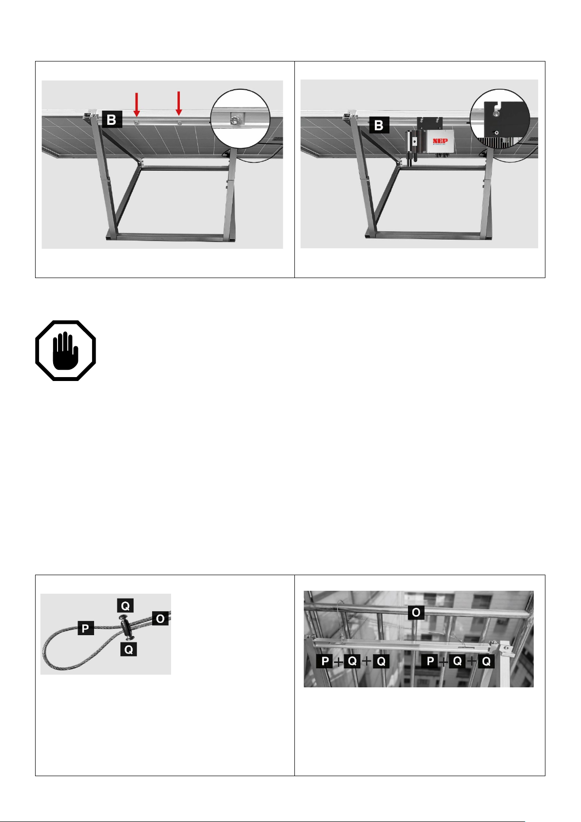
MONTAGGIO DELL’INVERTER ALLA STAFFA MOUNTING THE INVERTER TO THE BRACKET
1. Necessari Necessary: B - 1 (inverter)
Loosen the 2 screws in the crossbar of the bracket.
2. Necessari Necessary: B - T - R
1. Necessari Necessary: 2x O - 4x P - 8x Q - R
screws (Q).
2. Necessari Necessary: 2x O - 4x P - 8x Q - R
Allentare le 2 viti presenti nella traversa della staffa.
Inserire l’inverter e fissare le 2 viti di bloccaggio.
Insert the inverter and fix the 2 locking screws.
INSTALLAZIONE IN CASO DI RINGHIERA INSTALLATION IN CASE OF RAILING
Per poter installare ed utilizzare il kit sono necessarie le seguenti condizioni generali:
Ringhiera metallica costruita a regola d’arte e resistente a una spinta orizzontale di
almeno 200kg/m.
La ringhiera deve essere dotata di almeno due colonne con una distanza inferiore agli
80cm.
Lo spessore della ringhiera deve essere inferiore a 25mm, in caso sia superiore,
sostituire le zanche di fissaggio in dotazione con altre di dimensioni appropriate.
Deve essere predisposta una presa di corrente dedicata e visibilmente riconoscibile,
connessa direttamente al quadro elettrico
In order to install and use the kit, the following general conditions are required:
Metal railing built in a workmanlike manner and resistant to a horizontal thrust of at least 200kg/m.
The railing must be equipped with at least two columns with a distance of less than 80cm.
The thickness of the railing must be less than 25mm, if it is greater, replace the fixing clamps supplied
with others of appropriate dimensions.
A dedicated and visibly recognizable socket must be set up, connected directly to the electrical panel
MONTAGGIO DELLA STAFFA ALLA RINGHIERA MOUNTING THE BRACKET TO THE RAILING
Inserire un lato della
installata e farlo entrare nel secondo foro del blocca
cavo (P). Bloccare il cavo con le viti (Q).
Insert one side of the rope (O) into the first hole of
the cable lock (P), pass the rope inside the first slot
in the installed crosspiece and let it enter the second
hole of the cable lock (P). Lock the cable with the
fune (O) nel primo
foro del blocca cavo
(P), passare la fune
all’interno della prima
asola nella traversa
Completare il montaggio della fune (O)
assicurandola alla struttura della ringhiera
ripetendo i passaggi del punto 1.
Complete the assembly of the rope (O) by securing
it to the railing structure by repeating the steps in
point 1.
9

3. Necessari Necessary: 2x M
structure to the railing itself.
4. Necessari Necessary: 2x M
Utilizzando le altre 2 zanche di fissaggio (M),
B
bloccare la parte laterale della struttura alla
ringhiera stessa.
Con l’aiuto di almeno una seconda persona,
posizionare la struttura nella parte esterna della
ringhiera e, utilizzando 2 zanche di fissaggio (M),
bloccare la parte superiore della struttura alla
ringhiera stessa.
With the help of at least a second person, position
the structure on the outside of the railing and, using
2 fixing clamps (M), lock the upper part of the
Using the other 2 fixing clamps (M), lock the
lateral part of the structure to the railing itself.
COLLEGAMENTO TRA PANNELLO E INVERTER CONNECTION THE PANEL TO THE INVERTER
Connettere una estremità dei cavi in
dotazione ❼ ai cavi in uscita dal pannello e
collegare l’altra estremità all’ingresso CC
dell’inverter come rappresentato in figura B.
CONNESSIONE ALLA CORRENTE ELETTRICA CONNECTION TO ELECTRICITY
Si consiglia di far eseguire l’installazione da parte di un elettricista qualificato e l’impianto
deve soddisfare tutti i requisiti imposti dalla norma CEI 021. NON toccare alcun
componente attivo. Per prevenire il rischio di scosse elettriche durante l'installazione e la
manutenzione, assicurarsi che gli ingressi CA e CC siano scollegati. NON stare nei pressi del
prodotto in caso di condizioni meteorologiche avverse, inclusi temporali, fulmini, ecc.
It is advisable to have the installation carried out by a qualified electrician and the system must meet all the
requirements imposed by the CEI 021 standard. DO NOT touch any live component. TO prevent risk of
electric shock during installation and maintenance, please make sure that the AC and DC inputs are plugged
out. DO NOT stay close to the instruments while there is severe weather conditions including storm,
lightening etc.
Connect one end of the supplied cables ❼
to the cables coming out of the panel and
connect the other end to the DC input of the
inverter as shown in figure B.
10

Installazione del magnetotermico
Verificare la tensione presente sulla rete elettrica a cui connettere l’impianto. Gli intervalli accettabili
differiscono in base ai parametri della rete locale, in Europa: da L1 a N 230 Vac
Montare la piastra di fissaggio in una posizione adatta sul telaio del kit fotovoltaico. Utilizzare la scatola di
giunzione dotata in questo kit (❻). Collegare l'estremità aperta del cavo di interconnessione CA (❷) nella
scatola di giunzione utilizzando un pressacavo o un raccordo antistrappo appropriato. Il cavo di
interconnessione CA richiede un connettore antistrappo con un'apertura di circa 10mm di diametro.
1. Messa a terra
Ogni inverter ha un circuito di protezione di terra integrato. Il filo di messa a terra passa attraverso il cavo
principale e deve essere collegato saldamente al connettore di messa a terra nella scatola di giunzione.
2. Collegamento del cavo aperto al magnetotermico
Utilizzare il cavo ❸ e collegare il cavo blu al neutro del magnetotermico, il cavo marrone alla fase del
magnetotermico e il cavo giallo-verde alla terra presente all’interno della scatola di giunzione (❻).
3. Collegamento alla presa elettrica dedicata
ATTENZIONE: verificare che il magnetotermico sia in posizione di OFF, se non si è sicuri, non proseguire con
il montaggio e contattate un installatore qualificato.
Collegare la spina SCHUKO presente nel kit alla presa elettrica dedicata e ben riconoscibile.
1. Install the AC Branch Circuit Junction Box
Check the voltage present on the mains to connect the system to. Acceptable ranges differ according to
local network parameters, in Europe: L1 to N 230 Vac
Mount the fixing plate in a suitable position on the PV kit frame. Use the junction box equipped in this kit
(❻). Connect the open end of the AC interconnection cable (❷) into the junction box using an appropriate
strain relief or strain relief. The AC interconnect cable requires a strain relief connector with an opening
approximately 10mm in diameter.
2. Ground the system
Each BDM-600 has an integrated ground protection circuit. The grounding wire is through the trunk cable,
and should be securely connected to the ground connector in the junction box.
3. Open wire connection to circuit breaker
Use cable ❸ and connect the blue cable to the neutral of the circuit breaker, the brown cable to the phase
of the circuit breaker and the yellow-green cable to the earth present inside the junction box (❻).
4. Connection to the dedicated electrical socket
ATTENTION: check that the magneto-thermal switch is in the OFF position, if you are not sure, do not
continue with the assembly and contact a qualified installer.
Connect the SCHUKO plug present in the kit to the dedicated and easily recognizable electrical outlet.
PRIMO AVVIO E FUNZIONAMENTO FIRST START UP AND OPERATION
1. Portare su ON il magnetotermico CA o gli interruttori automatici su ciascun circuito derivato CA
dell’inverter.
2. Portare su ON l'interruttore principale CA della rete elettrica. Il sistema inizierà a produrre energia
dopo alcuni minuti di attesa.
1. Turn on the AC disconnects or circuit breakers on each inverter AC branch circuit.
2. Turn on the main utility-grid AC circuit breaker. Your system will start producing power after a few
minutes wait time.
11

Indicatori LED di funzionamento sull’inverter Operating LED indicators on the inverter
LED
STATUS
SIGNIFICATO
Verde lampeggiante ogni due secondi
Standby
OK
Rosso lampeggiante ogni due secondi
Standby
Errore
Verde lampeggiante ogni secondo
Generazione in corso
Standby
Rosso fisso
Generazione in corso
Problema di terra
LED
STATUS
SIGNIFICATO
Green light flashing every two seconds
Standby
OK
Red light flashing every two seconds
Standby
Errore
Green light flashing every one second
Producing
Standby
Rosso light fix
Producing Grounding
Fault
L’inverter si accende quando l’ingresso di corrente continua è sufficiente.
I LED si accenderanno come da tabella
The inverter is powered on when sufficient DC voltage from the module is applied. The status LED will start
flashing after sufficient DC power is applied as an indication that the inverter is live.
RISOLUZIONE DEI PROBLEMI TROUBLESHOOTING
In caso di problemi, l’inverter ha diverse funzionalità di protezione, fino all’arresto di erogazione della corrente.
Il messaggio di errore è trasmesso tramite la connessione Wi-Fi, e può essere monitorato attraverso la App
NEPviewer (riferirsi all’apposita sezione).
In case of fault, inverter has multiple protective functions and stops output power.
The fault message may be sent through WiFi internet connection, and can be monitored through NEPViewer
(please refer to the tech note “Configuring BDM WiFi
Error code Errore Error
Bit-0 Sovratensione CC DC over voltage
Bit-1 Sottotensione CC DC under voltage
Bit-2 Errore hardware hardware error
Bit-3 Sovratensione inverter Inverter over voltage
Bit-4 Frequenza superata Frequency over
Bit-5 Frequenza sotto Frequency under
Bit-6 Tensione CA RMS superata AC voltage RMS over
Bit-7 Tensione CA RMS sotto AC voltage RMS under
Bit-8 Tensione CA di picco superata Peak AC voltage over
Bit-9 Corrente CA RMS superata AC current RMS over
Bit-10 Corrente CA di picco superata Peak AC current over
Bit-11 Temperatura superata Temperature over
Bit-12 Errore ADC ADC error
Bit-13 Indicatore di errore GFDI GFDI fault indicator
Bit-14 Guasto relè Relay fault
Bit-15 Errore di comunicazione PLC PLC Communication Error
12

USO E INSTALLAZIONE DELL’APP DI CONTROLLO
USE AND INSTALLATION OF THE CONTROL APP
L’inverter in dotazione è dotato di connettività Wi-Fi, che ne consente la gestione tramite App dedicata.
Potenza EIRP ≤ 10 dBm. Frequenze 2400 – 2483,5 MHz. Versione software 1.0.
NOTA: Il dispositivo funziona con rete WI-FI a 2,4GHz. Disattivare o separare la rete 5GHz in quanto non compatibile.
Se non sai come dividere le bande del WI-FI, contatta il tuo gestore della linea internet per richiedere la separazione
delle reti 2,4GHz e 5GHz.
The supplied inverter is equipped with Wi-Fi connectivity, which allows it to be managed via a dedicated App. EIRP
power ≤ 10dBm. Frequencies 2400 – 2483.5 MHz. Software version 1.0.
NOTE: The device works with a 2.4GHz WI-FI network. Turn off or separate the 5GHz network as it is not compatible.
If you don't know how to divide the WI-FI bands, contact your internet line operator to request the separation of the
2.4GHz and 5GHz networks.
1: connetti l’inverter al pannello solare, e disconnetti la connessione CA, il LED
lampeggia ogni secondo.
1: connect the inverter to the solar panel, and disconnect the AC connection,
the LED flashes every second.
3: configurare il Wi-Fi. Aprire un
browser, visitare l’indirizzo
http://10.10.100.254 , cercare la
rete WiFi domestica e connettersi
con la password della rete stessa.
2: attendi un minuto, e connetti
lo smartphone al WiFi MIxxxxxxxx, dove xxxxxxxx sono le
ultime 8 cifre del seriale
dell’inverter. La password di
default è 12345678
2: Wait for one minute, and
connect to a WiFi network MIxxxxxxxx, where xxxxxxxx is the
barcode of the BDM-WiFi
inverter. Default PWD is
12345678
3: Configure BDM-WiFi. Open a
web browser, visit a URL address:
http://10.10.100.254 , search for
home WiFi, and digit home SSID
and password.
13

4: connettere la presa CA. Dopo 10 minuti, il LED
FISICHE – PHYSICAL
DIMENSIONI PANNELLO – DIMENSIONS
1765x1048x30mm
PESO COMPLESSIVO – TOTAL WEIGHT
24kg
ELETTRICHE – ELECTRIC
POTENZA MAX – MAX POWER
375W
TENSIONE PANNELLO – PANEL VOLTAGE
34,6V
EFFICIENZA – EFFICIENCY
>22%
CORRENTE – CURRENT
10,84A
TENSIONE DI USCITA INVERTER – INVERTER OUTPUT VOLTAGE
230V~ 50Hz
AMBIENTALI – ENVIRONMENT
VELOCITÀ MAX VENTO – WIND MAX SPEED
130km/h
TEMPERATURA DI ESERCIZIO – TEMPERATURE RANGE
-10 / 45°C
verde lampeggia ogni 3 secondi
4: Connect AC. After 10 minutes, LED flashes green
every 3 seconds.
5: Seguire le istruzioni sul sito https://user.nepreviewer.com per scaricare e installare la app dedicata NEPViewer.
Seguire le istruzioni.
5: Register the inverters on NEPViewer. Visit NEPViewerwebsite: https://user.nepviewer.com . Following instructions
and login. One site can have multiple inverters.
SPECIFICHE DEL PRODOTTO TECHNICAL SPECIFICATIONS
14

CARATTERISTICHE TECNICHE INVERTER INVERTER TECHNICAL FEATURES
MODEL
BDM-300
Module power range max
450W
MPPT voltage
22 – 55V
Startup voltage
16V
Max. input voltage
60V
Max. Input current
18A
Overvoltage protection category
II
Peak output power
290W
Continous output power
Potenza continua
250W
Output voltage
230V
Max continous output current
2A
Frequency
50Hz
THD
<3%
Overvoltage protection Category (AC)
III
MPPT efficiency
>99,5%
Night consumption
Consumo notturno
110mW
Operating temperature
-50 / +65°C
Humidity range
0 – 100%
Dimensions
180x186x25mm
Weight
1,5kg
DC connector
MC4
Communication method
PLC e Wi-Fi
Protection class
66 / 67
Potenza dei pannelli max
Tensione MPPT
Tensione di avvio
Tensione max in ingresso
Corrente max in ingresso
Categoria di protezione da sovratensione
Potenza max in uscita
Tensione in uscita
Corrente continua in uscita
Frequenza
Categoria di protezione da sovratensione (CA)
Efficienza MMPT
Temperatura di esercizio
Umidità di esercizio
Dimensioni
Peso
Connettore CC
Connettività
Grado di protezione IP
15

INFORMAZIONE AGLI UTENTI INFORMATION FOR THE USERS
Il triangolo che racchiude un fulmine indica che
cabinet.
Il triangolo che racchiude un punto esclamativo
manual.
I – Il simbolo del cassonetto barrato riportato sull’apparecchiatura indica che il prodotto alla fine della
propria vita utile deve essere raccolto separatamente dagli altri rifiuti. L’utente dovrà, pertanto,
conferire l’apparecchiatura integra dei componenti essenziali giunta a fine vita agli idonei centri di
raccolta differenziata dei rifiuti elettrici ed elettronici, oppure riconsegnarla al rivenditore al momento
dell’acquisto di nuova apparecchiatura di tipo equivalente (senza ulteriore acquisto, se di dimensioni
inferiori a 25 cm.). Lo smaltimento abusivo del prodotto da parte dell’utente comporta l’applicazione
delle sanzioni amministrative di cui al Decreto Legislativo N. 49 del 14 Marzo 2014.
GB – At the end of its life, the device has to be separated from the other waste. Consign the device and all its
components together to a center of electronical and electrotechnical waste recycling center, designated by your local
authorities.
MADE IN CHINA
importato e distribuito da Kon.El.Co. SpA, P.zza Don E. Mapelli 75, 20099 Sesto S. Giovanni (MI) - Italy
nell’apparecchio sono presenti alte tensioni che
possono mettere in grave pericolo l’incolumità di
chi apre il mobile
A lightning down inside the triangle, means that
inside the item there are high voltages, that can
cause grave danger to the operator who open the
indica che prima di iniziare ad utilizzare utilizzare
l’apparecchio è necessario essere a conoscenza
delle avvertenze riportate nel libretto di istruzioni.
The exclamation mark inside the triangle, means
that before using the item it is necessary to take
note of the warnings present inside the instruction
A causa della continua evoluzione dei prodotti, le caratteristiche ed il disegno di questo modello possono variare
senza preavviso.
Due to the continuous evolution of the products, the characteristics and design of this model may change without
notice.
DICHIARAZIONE DI CONFORMITA'
Il Fabbricante, Northern Electric Power Technology, ltd. - Changcheng South Road 6, Chengyang District, Qingdao,
China ZIP 266109, dichiara che il tipo di apparecchiatura inverter marca NEP, incluso nei kit solari Smart 3 e Smart 6,
cod. 34.5000.10 e 34.5000.30, marca ISNATCH, il cui funzionamento è descritto nel presente manuale, è conforme
alla Direttiva 2014/53/UE. Il testo della Dichiarazione di Conformità UE è disponibile al seguente indirizzo internet:
www.gbconIine.it.
DECLARATION OF CONFORMITY
The Manufacturer, Northern Electric Power Technology, ltd. - Changcheng South Road 6, Chengyang District,
Qingdao, China ZIP 266109, hereby declares that the inverter, NEP brand, embedded in Solar kit Smart 3 and Solar
kit Smart 6, cod. 34.5000.10 and 34.5000.30, brand name ISNATCH, whose use is described in this user manual, is in
compliance with Directive 2014/53/EU. The text of the EU Declaration of Conformity is available at the following
internet address: www.gbconIine.it.
16
 Loading...