

EFFECTIVE DATE 5-2008
THE GAYLORD INSTALLATION,
OPERATION & MAINTENANCE MANUAL
for
“XG” SERIES HOODS
GAYLORD INDUSTRIES
10900 S.W. AVERY STREET • TUALATIN, OREGON 97062 U.S.A.
1-800-547-9696 • 503-691-2010 • FAX: 503-692-6048 • email: info@gaylordusa.com
“Undisputed World Leader in
Engineered Systems for
Commercial Kitchens”
tm
GAYLORD INDUSTRIES
World Headquarters: 10900 S.W. Avery Street • Tualatin, Oregon 97062 U.S.A.
To Our Customers. . .
Congratulations on your recent purchase of a Gaylord
kitchen exhaust hood system. We are proud to be able to
provide you with a quality product that incorporates the lat-
est engineering concepts and is a result of over 50 years of
experience in the foodservice kitchen exhaust industry.
If you have other Gaylord equipment, such as a Gaylord Util-
ity Distribution System, Quencher Fire Protection System,
or Roof Top Air Handling Equipment, etc., please refer to
the corresponding supplementary equipment manuals.
If you have further questions, please call us toll free at
1-800-547-9696. We are more than happy to help.
Sincerely,
Gaylord Industries
PHONE: 503-691-2010 • 800-547-9696 • FAX: 503-692-6048 • email: gaylord@gaylordusa.com • www.gaylordusa.com
STREET ADDRESS: 10900 S.W. Avery Street, Tualatin, Oregon 97062-8549 U.S.A.
COMMERCIAL KITCHEN EXHAUST SYSTEMS • FIRE PROTECTION • UTILITY DISTRIBUTION • POLLUTION CONTROL
TABLE OF CONTENTS
OPERATION ............................................................................................................ 1
STANDARD MODELS ............................................................................................. 2
MAINTENANCE AND CLEANING INSTRUCTIONS ............................................... 3
TROUBLESHOOTING ............................................................................................. 4
MEASURING AIRFLOW ......................................................................................... 6
PARTS LIST ............................................................................................................ 7
INSTALLATION REQUIREMENTS .......................................................................... 8
HOOD START-UP INSPECTION REPORT ............................................................. 9
WARRANTY
ALL RIGHTS RESERVED. NO PART OF THIS BOOK MAY BE REPRODUCED, STORED
IN A RETRIEVAL SYSTEM, OR TRANSMITTED IN ANY FORM BY AN ELECTRIC, MECHANICAL, PHOTOCOPYING, RECORDING MEANS OR OTHERWISE WITHOUT PRIOR
WRITTEN PERMISSION OF GAYLORD INDUSTRIES COPYRIGHT 2008.
© Copyright 2008, Gaylord Industries
The manufacturer reserves the right to modify the materials and
specications resulting from a continuing program of product
improvement or the availability of new materials.
ADDITIONAL COPIES $7.00
FAN OPERATION
To operate the exhaust fan turn on the fan switch that is typically mounted on a wall near the hood. The “XG” hood may
be equipped with a fan, auto start controller, and/or light switch
mounted on the face of the hood.
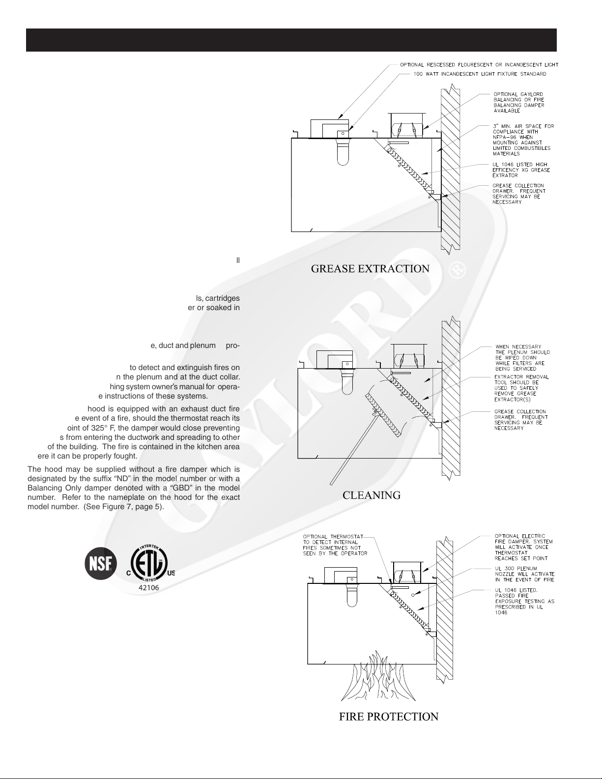
GREASE EXTRACTION (XG EXTRACTORS)
The Gaylord Industries Patent Pending XG Extractor Cartridge
is designed to deliver the absolute optimum in collection efciency at the lowest possible pressure drop. The units are ETL
listed to UL 1046 standard, and are also recognized as part of
an XG Ventilator. They are constructed of corrosion resistant
stainless steel and feature a GX style handle for easy removal
from the ventilator to which they are mounted. Another great
feature of the XG lter is that it can be opened up and turned
back on itself for easy and efcient dishwasher cleaning. The
opening of the lter is accomplished by a top mounted, dual
hinge and a set of snap buttons at the bottom to secure the
lter in position. The benet to such a design ensures that
restaurant employee’s will always have access to the inside of
the extractors for easy cleaning, and will not mistakenly install
the units in the opened, or disassemble position.
CLEANING
At the end of the cooking day, or at periodic intervals, cartridges
are removed and washed either in a dishwasher or soaked in
a deep well sink, scrubbed and rinsed.
OPERATION
FIRE PROTECTION
NFPA #96 requires the use of surface, duct and plenum pro-
tection on all hoods.
These systems are designed to detect and extinguish res on
the cooking surface, within the plenum and at the duct collar.
Refer to the re extinguishing system owner’s manual for opera-
tion and maintenance instructions of these systems.
The “XG-GFBD” hood is equipped with an exhaust duct re
damper. In the event of a re, should the thermostat reach its
activation point of 325° F, the damper would close preventing
the ames from entering the ductwork and spreading to other
parts of the building. The re is contained in the kitchen area
where it can be properly fought.
The hood may be supplied without a re damper which is
designated by the sufx “ND” in the model number or with a
Balancing Only damper denoted with a “GBD” in the model
number. Refer to the nameplate on the hood for the exact
model number. (See Figure 7, page 5).
1
STANDARD MODELS
Explanation of Prefixes and Suffixes
1. Series
(XG)
XG....................... Non water-wash ventilator with “XG” Super High Efficiency Extractors
XG-UV................. Non water-wash ventilator with “XG” Super High Efficiency Extractors
with ultraviolet lamps
2. Damper Type
GBD ................... Gaylord Balancing Damper (Standard)
GFBD................. Gaylord Fire Balancing Damper. Has a thermostatically activated (electric)
Fire/Balancing damper located at the duct collar. Can be used in the horizontal
pos
ition.
ND...................... No Damper
3. Style
BDL ................... Wall canopy style
BDL-CL .............. Island style for single line of cooking equipment using one extraction chamber
(Light-Medium Duty)
BDL-DS-CL ....... Island style for single line of cooking equipment using one extraction chamber
(Light-Heavy Duty) – w/ ONE Heavy Duty piece of Cooking Equip./Section
(max)
BDL-BBC-CL...... Island style for single line of cooking equipment using two extraction chambers
with one common exhaust duct
(L
ight-Extra Heavy Duty) or Multiple pieces of Heavy Duty Cooking Equip.
BDL-BB ............. Island style for back-to-back cooking equipment using two extraction chambers.
Has two separate exhaust ducts
MODEL “XG-BDL”
APPLICATION - Wall mounted
canopy style.
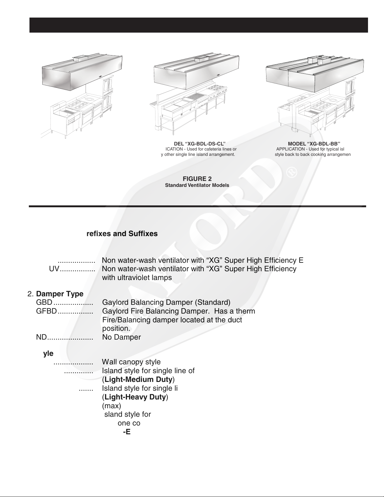
MODEL “XG-BDL-DS-CL”
APPLICATION - Used for cafeteria lines or
any other single line island arrangement.
FIGURE 2
Standard Ventilator Models
MODEL “XG-BDL-BB”
APPLICATION - Used for typical island
style back to back cooking arrangement.
2

MAINTENANCE AND CLEANING INSTRUCTIONS
ELUDEHCSNOITCEPSNIMETSYSTSUAHXE
snoitarepognikoocleufdilosgnivressmetsySylhtnoM
snoitarepognikoocemulov-hgihgnivressmetsys
kowrogniliorbrahc,gnikoocruoh-42sahcus
gnikooc
ylretrauQ
gnikoocemulov-etaredomgnivressmetsys
snoitarepo
yllaunna-imes
,snoitarepognikoocemulov-wolgnivressmetsys
lanosaes,spmacyad,sehcruhcsahcus
sretnecroinesro,sessenisub
yllaunna
At the end of each cooking day, the exposed interior surfaces of the hood
should be wiped down and the grease cup emptied. During the course of
operation, grease particles are gradually collecting inside the cartridge
extractors. Daily, or at periodic intervals, depending on the type of cooking, the cartridge extractors must be removed and cleaned. To clean,
proceed as follows:
1. Remove lters. CAUTION: Care should be taken when removing
lters, especially over fryers. It is recommended that the cooking
equipment be cooled down and the fryers be covered prior to removing
lters. To remove, lift up slightly on lters and pull out at the bottom,
then straight down.
2. Filters may be cleaned either by using a dishwasher or by soaking in
deep well sink using hot water with a degreasing detergent, scrubbed
and rinsed. Prior to cleaning, open the XG extractor to gain access
to the lters interior. Formula G-510 is highly recommended for this
application. For information contact:
20/10 Products
P.O. Box 7609
Salem, Oregon 97303
Phone: 800-286-2010
Fax: 503-363-4296
email: twentyten@juno.com
3. With extractors removed, wipe and clean the back wall and top of the
plenum area and the grease gutter with hot detergent water. NOTE: If
steam or hot water pressure wash is used for periodic cleaning of the
interior, remove the grease drawer and connect a hose to the gutter
drain and lead it to a oor sink or large bucket to drain off water.
4. Replace extractors. Be sure to replace extractors with bafes running
vertical as shown in Fig. 5.
IMPORTANT NOTE: In the event of a re the thermostat must be replaced.
(Applicable to GFBD models only.)
FIGURE 4
NOTE: NEVER OPERATE THE HOOD
IF THE FILTERS ARE NOT IN PLACE.
INSPECTION AND CLEANING REQUIREMENTS
The 1998 edition of NFPA-96 (Standard for Ventilation Control and Fire
Protection of Commercial Cooking Operations) require that hoods, ducts
and exhaust fans be inspected by a properly trained, qualied and certied
company or person(s) in accordance with the following table.
Upon inspection, if found to be contaminated with deposits from grease-
laden vapors, the entire exhaust system shall be cleaned by a properly
trained, qualied, and certied company or person(s) acceptable to the
authority having jurisdiction in accordance.
When a vent cleaning service is used, a certicate showing date of in-
spection or cleaning shall be maintained on the premises. After cleaning
is completed, the vent cleaning contractor shall place or display within
the kitchen area a label indicating the date cleaned and the name of the
servicing company. It shall also indicate areas not cleaned.
Facto r y tr a ined ser vi c e agenci e s ar e cer tified by Gayl o r d
Industries to perform these inspections. For the name and phone
number of your nearest agent, call 1-800-547-9696 or send an e-mail to
info@gaylordusa.com.
FIGURE 5
NOTE: EXTRACTORS MUST BE INSTALLED WITH
BAFFLES RUNNING VERTICAL AS SHOWN.
CAUTION: Care should be taken when removing
extractors, especially over fryers. It is recommended that the cooking equipment be cooled down and
the fryers be covered prior to removing lters.
FIGURE 6
NOTE: FILTERS SHOULD BE OPENED PRIOR TO
CLEANING.
3

MOTPMYSMELBORPELBISSOPNOITCAEVITCERROC
SSOLEKOMS
.1 otnsidooH-ssoLekomS
.ylreporpgnitsuahxe
.A
.B
.C
.D
.E
tsuahxenwostievahtsumdoohehT
sahcus,tsuahxerehtoondnametsys
.tiotnideitebdluohs,sdoohrehsawhsid
.sresuffidriapu-ekamdecalpylreporpmI
.riapu-ekametauqedanI
.egrahcsidnaftsuahxE
.1
.2
.3
.4
.5
.1
.1
.2
.3
.1
.1
.2
.naftsuahxeehtnotlebgnippilsronekorB
.leehwnaftsuahxeehtfonoitatorreporP
tsumnaf(naftsuahxefoezisreporP
.)gnitareta
lpemanreviled
.nepotfellenapnoitcepsnikrowtcuD
nironepotonrepmaderiftcudtsuahxE
.noitisopreporp
erehttahtyfirevdnametsystcudtcepsnI
fI.nideitsmetsysdoohnonrehtoonera
.devomerebtsumyehtos
ylekillliwdoohehttadetceridriapu-ekaM
wolfriaehtgnitpursidstfardssorcetaerc
tceridotsrevuolehttsujdA.doohehtotni
.doohehtmorfyawariapu-ekameht
hguorhtdereviledebdluohsriapu-ekaM
detubirtsiddna,thgiehgniliectasretsiger
.aeraneh
ctikehttuohguorht
ehtraendetacolsretsigerriapu-ekaM
otdetsujdaebdluohssrevuoleht,dooh
.doohehtmorfyawariaehttcerid
ehttariapu-ekamgnicrofrognitceriD
stfardssorcsetaercyllacipytdooh
.ssolekomsnignitluser
rofdeilppusebtsumriapu-ekaM
llahguorhtdetsuahxeriafotnemecalper
elur"larenegA.smetsystsuahxenehctik
ehtfo%06ot%55tahtsi"bmuhtfo
,hserfebdluohsriatnemecalper
ria)deloocrodetaeh(,denoitidnoc
ehthtiw,aeranehctikeh
totnithguorb
otniwolfotdewolla%54ot%04gniniamer
.saeratnecajdamorfnehctikeht
ehtrevoneercsonebdluohserehT
ebdluohsti,dnuofsienofI.egrahcsid
.devomer
ebtondluohsegrahcsidfonoitceridehT
drawnwodronsdniwgniliaverpehtotni
ylhgihsiegrahcsidlacitrevA.foorehtotno
.dednemmocer
NOITCARTXEESAERG
.1
2
ABHoods with too much air being pulled
through them can have grease pull through.
Hoods pulling too much air through the
extractor can cause excessive noise.
.12To see if you are pulling the proper amount
of air through the system. See pg. 6 & 7.
Adjust motor / fan speed down to eliminate
excessive noise. After doing so, verify the
hood is properly capturing all smoke.
Low Airow - Static pressure at the hoods
static tap should be in accordance with
charts pg. 6 & 7
Poor Grease Extraction.
Noise.
TROUBLE-SHOOTING
4

3130583-421
TROUBLE-SHOOTING
MOTPMYSMELBORPELBISSOPNOITCAEVITCERROC
NAFTSUAHXE
.1
.2
ehtotnodenrutsihctiwsnafehtnehwfI
naftsuahxeehttubnoitsoptsuahxe
.noemoctonseod
ehtotnodenrutsihctiwsnafehtnehwfI
dellupgniebtonsiria,noitisoptsuahxe
ehtraehnacuoytubdoohehthguorht
.gninnurnaf
.A
.B
.C
.D
.E
.A
citengamehtnorotcetorpdaolrevO
.deppirtretrats
epyt)citamotuA/ffOdnaH(AOHnafI
eht,desusihctiwsretratscitengam
devomneebevahyamhctiwsrotceles
.noitisopcitamot
uaehtmorf
.deppirtrekaerbtiucricnaftsuahxE
desufahtiwdeppiuqesimetsysehtfI
a,naftsuahxeehtrofhctiwstcennocsid
.tuonwolbevahyamsesufroesuf
deriwneebtonsahhctiwsffo/nonaF
.ylreporp
fi,ralloctcudtsuahxetarepmaderiF
.desolcsah,deppiuqe
.1
.1
ehtnonottub"teseR"ehthsuP
nafehtnrutdnaretratscitengam
.noitisop"nO"ehtothctiws
ehtotrotcelesnrutdnahctiwskcehC
.noitisopcitamotua
.rekaerbtiucrictes-eR
dnasesuffoytiunitnockcehC
.yrassecenfiecalper
sihtnimargaidgniriwotrefeR
.eriw-erdnalaunam
otslenapsseccayrassecennepO
ekatdnatcepsni,ralloctcud
.noitcaevitcerroc
2. Verify damper motor proper operation
and that it is getting its requirement of
power.
TOTAL EXHAUST
CFM HERE
5
FIGURE 7
ETL Listed Nameplate
The total minimum required exhaust
volume can be found stamped on
the ETL nameplate located on each
hood section. Minimum listed values
do not always correspond to the
design requirements for each hood
section.

MEASURING AIRFLOW
Measuring Airflow
The XG hood has been designed to give you
an approximate airflow per linear foot of hood
based on the static pressure measured at a
particular location on you XG hood section.
The method will require the balancer to have a
manometer, (Dwyer 475-00 FM
recommended), which he/she will use to get a
static pressure measurement for every hood
section. The static tap, as seen in fig. 8, will be
located behind a small 4 to 6 screw access
cover, located directly above your f
ilters.
Instructions:
1. Turn on the exhaust fan to the hood
section you intend to measure the
exhaust airflow.
2. Remove access cover as seen in fig. 8.
3. Locate the static tap, and remove the
sealing boot.
4. Zero you Dwyer 475-00 Digital
Manometer.
5. Take the 1/8” vinyl tube attached to your
Dwyer 475-00 Digital Manometer and
attach it to the static tap.
6. Record the value indicated on your
meter.
7. Compare your recorded values to Fig. 9,
Airflow vs. Static Tap Chart to determine
your rate of
flow
for the hood per unit length
of the hood. Total flow will be the CFM/LF
obtained from Fig. 9 multiplied by the
length of the ventilator section.
8. Design values will be noted on the
listing label attached to the inside of the
ventilator, or sticker attached to the
inside of the access cover.
Fig. 9, Airflow vs. Static Tap Chart
Balancing
Hood system flow rates are to be adjusted to
obtain the correct pressures noted above. Flow
adjustment for the XG ventilator is to be done by
either manipulation of the Gaylord Industries
GBD, or GFBD balancing dampers, or by fan
pulley adjustment. Reference your GBD/GFBD
technical manual for more details
Consult the Gaylord Industries factory for Listed,
and recommended airflow rates over particular
equipment line up, as well as best practice
system balancing, and
equipment place.
BDL Hood DS-CL Hood
SP Tap CFM/LF SP Tap CFM/LF
0.07 100 0.10 200
0.10 120 0.12 240
0.15 150 0.15 280
0.19 170 0.17 300
0.23 190 0.21 340
0.28 210 0.25 380
0.30 220 0.34 440
0.36 240 0.37 460
0.43 265
* Values need to be
multiplied by the
hood sections overall
length to get the total
CFM.
0.55 300
0.63 320
0.75 350
Figure 8
6

ONTRAPNOITPIRCSEDNOITARTSULLI
75963 XG Extractor
XG-DS Extractor
10307
91110 edtsorF-ebolGthgiL
41318 chtiwSpotS/tratS051-C
GX Handle
19350
Static Pressure Tap
18400
Extractor Removal Tool
(For 250 - 400 CFM/Lin. Ft. Extractors)
Kason
INCANDESCENT LIGHT LENS & FRAME
12” x 12” Recessed Light Lens & Retainer
FLUORESCENT LIGHT LENS & FRAME
2 Ft. Recessed Light Lens & Retainer
3 Ft. Recessed Light Lens & Retainer
4 Ft. Recessed Light Lens & Retainer
13211
13210
10111
10112
19872
EXHAUST DUCT THERMOSTATS
6” NC 325° F
19176
Damper Control Motor (24 volt)
For GFBD Model Dampers
Control
GAYLORD
75964
PARTS LIST
7

120 VOLT HOLDING
COIL IN MAGNETIC
starTER SWITCH
TYPICAL FAN SWITCH WIRING
H
N
FAN
SWITCH
ELECTRICAL SERVICE
BY OTHERS
INSTALLATION REQUIREMENTS
H
N
LIGHT
SWITCH
LIGHT
FIXTURES
INTERCONNECTING WIRING
BETWEEN HOOD SECTIONS
BY ELECTRICAL CONTRACTOR
HOOD WIRING
ELECTRICAL SERVICE
BY OTHERS
tUOMMUMINIMDeDNeMMOCerseCIveDGNI
HtGNeLNOItCessDOrGNIGNaHStLOBteKCarB
"0-"7NaHtsseL22
retaerGDNa"0-"733
ELECTRICAL
1. If hoods are equipped with light xtures, provide a separate 120 volt or 220 volt
lighting circuit to light J-box on the hood. Hood may be equipped with built-in
light switch.
2. If hood is provided with a built-in fan switch provide a separate 120 volt or 220
volt circuit to the fan switch J-box mounted on top of the hood. Fan switch is rated
for 20 amps, 277 volts, 1 h.p. at 120 volts, 2 h.p. at 220 volts, 16 amps max.
INSTALLATION
2. Hood to be installed in accordance with NFPA-96 Standard for Ventilation Control
and Fire Protection of Commercial Cooking Operations and all other local ap-
plicable codes. Contractors must review applicable codes with code authorities
before approving drawings for fabrication. Special attention must be given to
code regulations relative to clearances from surrounding combustible construc-
tions (walls, ceilings, etc.).
3. If the hood is manufactured in multiple sections and include light xtures, the
electrical contractor is responsible for inter-wiring the lights between hood sec-
tions.
4. Exhaust duct must be continuously welded to the hood duct collar. All ductwork
beyond the hood duct take-off collar must be installed, in accordance with ap-
plicable codes. Exhaust ducts must be grease and water tight with continuous
external welds.
5. All hoods are equipped with continuous hanging anges. Hanging rods to be
supplied by hood installer. Hanging weight of the hood(s) is noted on the sub-
mittal drawing.
6. Hoods are manufactured in strict accordance with Gaylord specications and
the Gaylord UL Procedure Manual.
7. Hoods are constructed of 18 Ga. stainless steel, Type 304, No. 4 nish unless
otherwise noted on drawings.
AIR FLOW RATES
8. The exhaust air ow rates (and supply if part of the hood) must be set at the
rate stamped on the hood nameplate. The exhaust volumes (and supply when
provided) were established under controlled laboratory conditions and greater
exhaust and/or lesser supply may be required for complete vapor and smoke
removal in specic situations.
FIRE EXTINGUISHING SYSTEM
9. Fire extinguishing system furnished and installed by contractor must be in accordance with the terms of it’s listing and the applicable NFPA codes.
10.Caution: Fire extinguishing system piping installed on the hood at job site
should be coordinated with the Gaylord Manufacturer to ensure piping does not
interfere with hood’s operation/performance. Improper installation may void UL
Listings of the hood.
11. IMPORTANT NOTE: NFPA-96 requires that all gas cooking equipment and
electric cooking equipment, that is protected by surface re protection, must
automatically shut off upon activation of the re extinguishing system.
12. IMPORTANT NOTE: Most building departments require separate hood and
re protection permits prior to installation. The hood permit is typically obtained
through the plan review department and the re protection permit from the re
prevention bureau. It is the responsibility of the installing contractor to check
with local building departments for their requirements and to obtain necessary
permits.
8

________________________________________________ Date ________________________
ELECTRIC DAMPER TEST (If equipped):
1. Remove one or more lters or cartridge extractors so the damper is visible. Turn on the exhaust fan.
A. The damper should move to the fully opened position in approx. 1 minute 15 seconds.
_____Yes ___No
B. The exhaust fan came on ___Yes ___No
2. Turn off the exhaust fan.
A. The damper should move to the fully closed position in approx. 15 seconds_____Yes_____No
B. The exhaust fan shut off ___Yes ___No
INSTALLATION INCLUDES THE FOLLOWING:
Gaylord Auto Start Controller
Gaylord Clearair Pollution Control Unit (RSPC) The Gaylord “Quencher” Fire Protection System
Gaylord Distributor (UDS) Wet Chemical Fire Protection System
Personnel provided with ventilator technical manual________Yes________No
Inspection Witnessed By (Print Name)_________________________________________________________
Signature
Comments ____________________________________________________________________________
______________________________________________________________________________________
______________________________________________________________________________________
______________________________________________________________________________________
______________________________________________________________________________________
______________________________________________________________________________________
______________________________________________________________________________________
______________________________________________________________________________________
Distribution: WHITE-Gaylord Industries YELLOW-Customer PINK-Dealer GOLDENROD-Sales Rep
GAYLORD INDUSTRIES • 10900 S.W. Avery Street • Tualatin, OR 97062 USA
PHONE:1-503-691-2010 • FAX: 1-503-692-6048 • email:info@gaylordusa.com
For Model “XG” Series Hoods
* GBD - Manual set Balancing Damper
HOOD START-UP INSPECTION REPORT
City/State Zip
City / State Zip
__________________________________________ Phone # _____________________ CSA Contacted ________________________________________________________________________
Job Name ___________________________________________________ ________________________ Gaylord Representative ____________________________________________________________
Address _____________________________________________________ _______________________ Representative Company Name _____________________________________________________
____________________________________________________________ _______________________ File Number ________________________________________________Date ________________
Facility Contact Name
MAKE-UP AIR
1. Kitchen make-up air supply is turned on______Yes______No
2. Type of make-up air
Ceiling Registers Built into Hood
Ceiling Linear Diffusers Other
3. If ceiling register or linear diffusers, note approximate distance from face of hood
_____________________________________________________________
** GFBD - Electric Balancing / Fire Damper
HOOD SERIES
XG-GBD-BDL (GBD*)
XG-GFBD-BDL (GFBD**)
*** ND - No Damper
XG-ND-BDL (ND***)
XG-GBD-BDL-DS-CL
XG-GFBD-BDL-DS-CL
XG-ND-BDL-DS-CL
AIR VOLUME READINGS
10
Turn on exhaust fan and record inlet velocities in accordance with the instructions in the “XG” Series Installation,
Operation and Maintanence manual.
ITEM NO. HOOD SERIAL NO. STATIC PRESSURE PLENUM CFM / LF
Form No. XGSUR 0508

LIMITED WARRANTY
LIMITED WARRANTY
For “XG” Series Ventilators
May 2008
The Gaylord “XG” Series hood and component parts furnished with the hood by Gaylord Industries or the
Licensed Gaylord Manufacturer are warranted by Gaylord Industries or the Licensed Gaylord Manufacturer
producing ventilator to be free from defects of material and workmanship under normal use when installed,
operated and serviced in accordance with factory recommendations.
Gaylord Industries or the Licensed Gaylord Manufacturer’s obligation under this warranty and any warran-
ties implied in law shall be limited to repairing or replacing at its option any part of said equipment when
Gaylord Industries or the Licensed Gaylord Manufacturer’s examination shall disclose to its satisfaction to
be thus defective, for a period of one (1) year from date of benecial use, or eighteen months from date
of shipment, whichever occurs rst, provided proper and acceptable evidence of such is recorder at the
factory. GAYLORD INDUSTRIES OR THE LICENSED GAYLORD MANUFACTURER SHALL NOT BE
RESPONSIBLE FOR INCIDENTAL OR CONSEQUENTIAL DAMAGES RESULTING FROM A BREACH
OF THIS WARRANTY.
In the United States the labor required to make repairs and replacements under this warranty shall be
furnished by Gaylord Industries or the Licensed Gaylord Manufacturer or its authorized representative.
Such labor shall only be provided Mondays through Fridays between the hours of 8 a.m. and 4 p.m. Re-
quests for repairs or replacement parts should be made to GAYLORD INDUSTRIES, 10900 SW Avery
Street, Tualatin, Oregon 97062.
Outside the United States, all replacement parts furnished under this warranty shall be F.O.B. Gaylord
Industries, Tualatin, Oregon U.S.A. The owner shall pay the necessary freight delivery charges, and the
necessary labor for removal and installation of parts, and any tariffs, duties or taxes.
This warranty does not cover routine maintenance or malfunctions or improper operation caused by
uctuating electrical power or power surges, and improper exhaust fan operation.
This is the sole warranty with respect to the aforesaid items. NEITHER GAYLORD INDUSTRIES NOR
THE GAYLORD LICENSEE NOR ANY OTHER PARTY MAKES ANY OTHER WARRANTY OF ANY KIND
WHATSOEVER, EXPRESSED OR IMPLIED, AND ALL IMPLIED WARRANTIES OF MERCHANTABILITY
AND FITNESS FOR A PARTICULAR PURPOSE WHICH EXCEED THE AFORESAID OBLIGATIONS ARE
HEREBY DISCLAIMED AND EXCLUDED FROM THIS AGREEMENT.

WORLDWIDE SALES, MANUFACTURING AND SERVICE
FOR THE NAME AND LOCATION OF THE NEAREST
CERTIFIED SERVICE AGENCY, CALL OR WRITE TO:
GAYLORD INDUSTRIES
10900 s.w. avery street
TUALATIN, OREGON 97062 U.S.A
Call: 503-691-2010
1-800-547-9696
Fax: 503-692-6048
email: info@gaylordusa.com
LOCAL SERVICE AGENCY
FORM NO. TM-XG 0508 © COPYRIGHT 2008, GAYLORD INDUSTRIES LITHO IN U.S.A.
 Loading...