

THE
GAYLORD VENTILATOR
EFFECTIVE DA TE 4-05
TECHNICAL MANUAL
FOR THE Ultima VentTM “GX2-UV” SERIES
NON WATER-WASH VENTILATORS
GAYLORD INDUSTRIES
10900 S.W. AVERY STREET • TUALATIN, OREGON 97062-1149 U.S.A.
800-547-9696 • 503-691-2010 • FAX: 503-692-6048 • email: info@gaylordusa.com
“Undisputed World Leader in
Engineered Systems for
Commercial Kitchens”
tm
GAYLORD INDUSTRIES
World Headquarters: 10900 S.W . Avery Street • T ualatin, Oregon 97062-1149 U .S .A .
To Our Customers. . .
Congratulations on your recent purchase of a Gaylord
kitchen exhaust hood system. We are proud to be ab le
to provide you with a quality product that incorporates
the latest engineering concepts and is a result of over
50 years of experience in the foodservice kitchen
exhaust industry.
If you have other Gaylord equipment such as a Gaylord
Utility Distribution System, Quencher Fire Protection Sys-
tem, or Roof Top Air Handling Equipment, etc., please
refer to the corresponding supplementary equipment
manuals.
If you have further questions, please call us toll free at
1-800-547-9696 or email:info@gaylordusa.com. We are
more than happy to help.
Sincerely,
Gaylord Industries
PHONE: 503-691-2010 • 800-547-9696 • FAX: 503-692-6048 • email: gaylord@gaylordusa.com • www.gaylordusa.com
COMMERCIAL KITCHEN EXHAUST SYSTEMS • FIRE PROTECTION • UTILITY DISTRIBUTION • ROOF TOP UNITS • POLLUTION CONTROL
STREET ADDRESS: 10900 S.W. Avery Street, Tualatin, Oregon 97062-8549 U.S.A.
2
TABLE OF CONTENTS
“GX2-UV” VENTILA TOR MODEL DESCRIPTION“ ..............................................................4
“GX2-UV” SERIES PRINCIPLE OF OPERA TION.......................................................... 5 – 7
MAINTENANCE AND CLEANING INSTRUCTIONS ............................................................. 8
UV PREVENTIVE MAINTENANCE .......................................................................................9
SAFETY CONCERNS WITH UV........................................................................................ 10
START-UP PROCEDURES .............................................................................................. 11
MEASURING INLET SLOT VELOCITY ....................................................................... 12 –14
TROUBLESHOOTING ............................................................................................... 15 – 20
MODEL CUV-100 SERIES CONTROL CABINET .............................................................21
MODEL CUV-100 SERIES CONTROL.............................................................................. 22
P ARTS LIST...................................................................................................................... 23
UV MODULE P ARTS ......................................................................................................... 24
GEM SYSTEM DIAGRAM...................................................................................................25
UV HOOD WIRING ............................................................................................................26
WIRING DIAGRAMS................................................................................................... 27 – 28
ST ANDARD VENTILA TOR MODELS.................................................................................29
METRIC CONVERSION CHART ....................................................................................... 30
START-UP INSPECTION REPORT ..................................................................................31
WARRANTY ............................................................................................... Inside back cover
PATENT NUMBERS
U.S.A.: 4,266,529
4,281,635
4,356,870
CANADA: 1,139,151
1,155,366
GERMANY: 8,034,240
ALL RIGHTS RESERVED. NO PART OF THIS BOOK MAY BE REPRODUCED, STORED
IN A RETRIEVAL SYSTEM, OR TRANSMITTED IN ANY FORM BY AN ELECTRIC, MECHANICAL, PHOTOCOPYING, RECORDING MEANS OR O THERWISE WITHOUT PRIOR
WRITTEN PERMISSION OF GAYLORD INDUSTRIES COPYRIGHT 2004.
© Copyright 2005, Gaylord Industries
The manufacturer reserves the right to modify the materials and
specifications resulting from a continuing program of product improvement or the availability of new materials.
ADDITIONAL COPIES $10.00
3
“GX2-UV” VENTILATOR MODEL DESCRIPTION
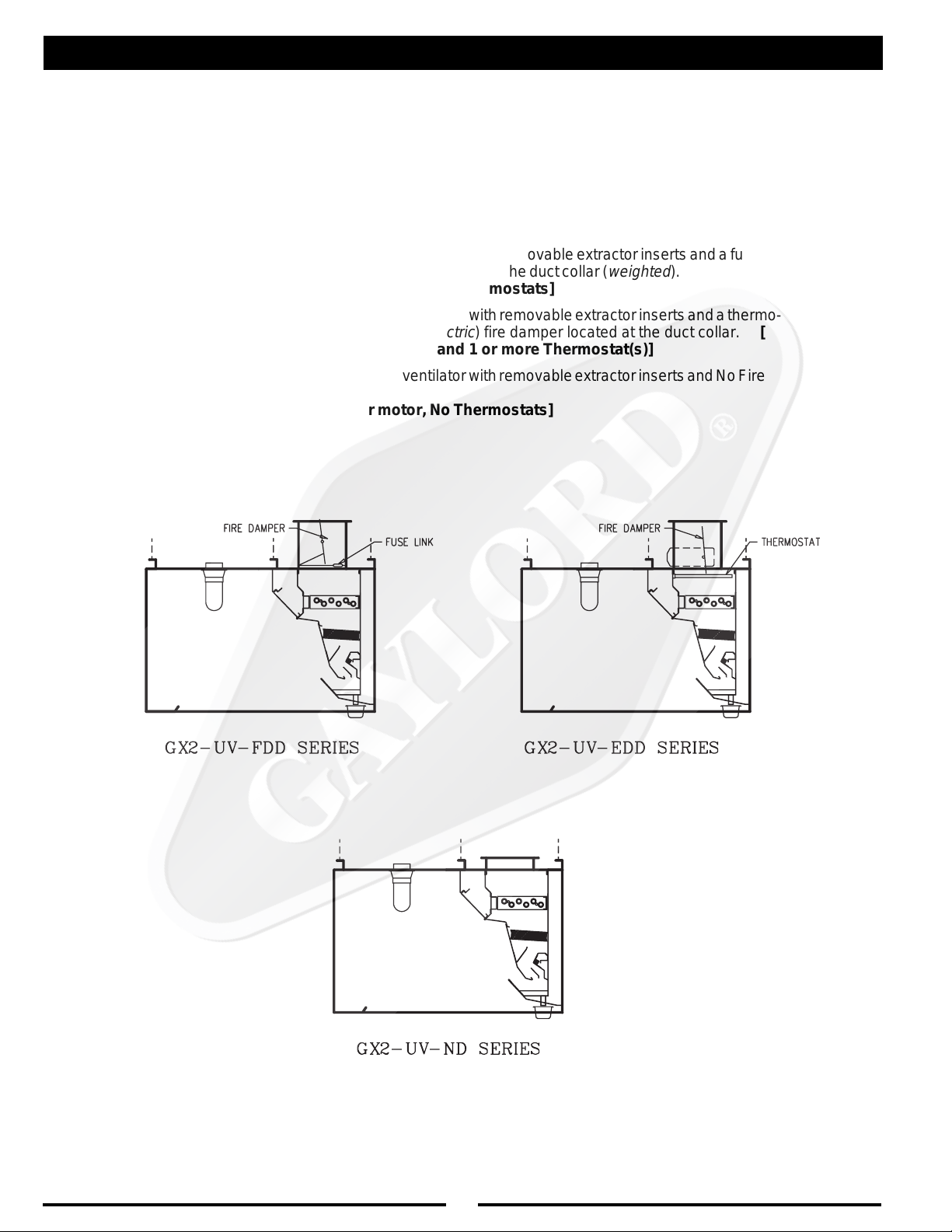
There are 3 different types of “GX2-UV” “Grand Gaylord” non water-wash ventilators. The differences
involve the type and location of fire damper and whether the ventilator has a fire damper. The first part
of the model number indicates the type of ventilator, see below:
Explanation of Prefixes:
GX2-UV-FDD Non water-wash ventilator with removable extractor inserts and a fuse link
activated fire damper located at the duct collar (
[No Damper motor, No Thermostats]
GX2-UV-EDD Non water-wash ventilator with removable extractor inserts and a thermo-
statically activated (
With Damper motor and 1 or more Thermostat(s)]
GX2-UV-ND Non water-wash ventilator with removable extractor inserts and No Fire
Damper.
[No damper motor, No Thermostats]
electric
) fire damper located at the duct collar. [
weighted
).
4
“GX2-UV” SERIES PRINCIPLE OF OPERATION
The Gaylord “GX2-UV” Series Non Water-Wash Ventilator
offers simplicity, economy and performance that no other
ventilator can offer. The unique “extractor insert” gives a
grease extraction efficiency far superior to that of a typical
baffle filter. The Gaylord “GX2-UV” Series Ventilators are UL
Listed and meet all the requirements of NFPA #96 and the
International Mechanical Code.
EXHAUST FAN OPERATION
The exhaust fan is controlled by the Gaylord CUV-100 Control
Cabinet. The cabinet is usually located on a wall near the
ventilator. When the control is turned on, the exhaust fan and
UV Lamps will come on.
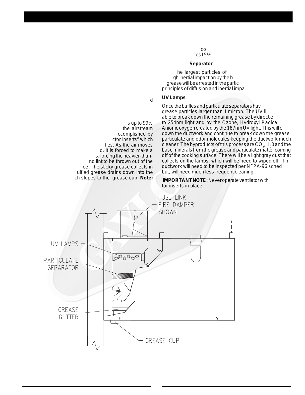
GREASE EXTRACTION
The Gaylord “GX2-UV” Series Ventilator extracts up to 99%
of the grease, dust, and lint particles from the airstream
passing through it. Grease extraction is accomplished by
unique, removable stainless steel “extractor inserts” which
incorporate a series of horizontal baffles. As the air moves
through the extractor at high speed, it is forced to make a
series of turns around these baffles, forcing the heavier-than-
air particles of grease, dust, and lint to be thrown out of the
airstream by centrifugal force. The sticky grease collects in
the extractor and the liquified grease drains down into the
main grease gutter which slopes to the grease cup. Note:
Some ventilators may be equipped with optional “Custom Air”
baffles (shown dotted) to reduce the exhaust volume over
specific light duty cooking appliances. The extractor inserts
come in two sizes15½" (5.6 lbs.) and 19½" (6.75 lbs.).
Particulate Separator
Once the largest particles of grease have been captured
through inertial impaction by the baffles. The smaller particles
of grease will be arrested in the particulate separator using the
principles of diffusion and inertial impaction.
UV Lamps
Once the baffles and particulate separators have collected the
grease particles larger than 1 micron. The UV lights will be
able to break down the remaining grease by direct exposure
to 254nm light and by the Ozone, Hydroxyl Radicals and
Anionic oxygen created by the 187nm UV light. This will carry
down the ductwork and continue to break down the grease,
particulate and odor molecules keeping the ductwork much
cleaner. The byproducts of this process are CO2, H20 and the
base minerals from the grease and particulate matter coming
off of the cooking surface. There will be a light gray dust that
collects on the lamps, which will be need to wiped off. The
ductwork will need to be inspected per NFPA-96 schedules
but, will need much less frequent cleaning.
IMPORTANT NOTE: Never operate ventilator without extractor inserts in place.
GREASE EXTRACTION
FIG. 1
5
“GX2-UV” SERIES PRINCIPLE OF OPERATION
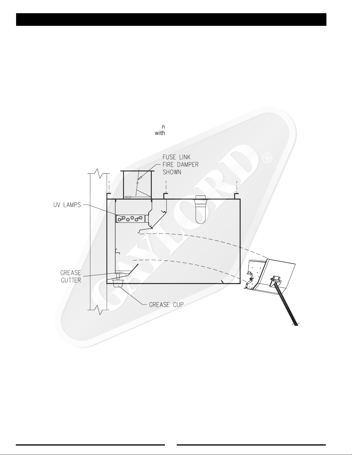
CLEANING
At the end of the cooking day the exhaust fan is turned off at
the CUV-100 control. After the fan has been turned off, the
extractor inserts and particulate separators are removed and
can be washed either in a dishwasher or soaked and rinsed
off. The grease cup is also removed and emptied at this time.
To ease in the removal of the extractor inserts, an “Extractor
Removal Tool” is available which eliminates the need for
kitchen personnel to climb up on the cooking equipment, or
up a ladder.
The UV lamps will develop a coating of dust. This coating must
be removed for optimum performance. Therefore, once a week
while the cartridges are removed, inspect the lamps and clean
as needed. Use a clean dry cloth and if necessary wash with
mild detergent and water first.
FIG. 2
6
“GX2-UV” SERIES PRINCIPLE OF OPERATION
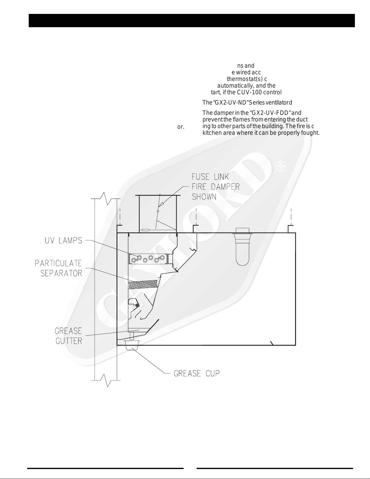
FIRE PROTECTION
NFPA-96 requires the use of Surface Fire Protection (Duct,
Plenum, Surface/Appliance) on all hoods. It is these systems
that are the first line of defense against equipment fires.
The “GX2-UV-FDD” Series ventilator incorporates a fuse link
damper at the duct collar. In the event of a fire, should the
fuse link at the duct collar reach 280°F, the fuse link melts
allowing the damper to close. (See Fig. 3) After the fire is
extinguished the fuse link(s) in the duct collar needs to be
replaced and the damper reset.
The “GX2-UV-EDD” Series ventilator incorporates an Electric
Damper at the Duct collar and thermostat(s), which are
located at the point where the ductwork joins the ventilator.
When the temperature of the conveying airstream, which
must pass over the thermostat(s), reaches 250°F, the
Electric Damper at the Duct collar closes and the Exhaust
and Supply fans and UV Lamps shut off, when the ventilator
and fans are wired according to Gaylord’s wiring diagram.
After the thermostat(s) cool below 250°F the damper will
reset automatically, and the Exhaust and Supply fans will
restart, if the CUV-100 control is turned “ON”.
The “GX2-UV-ND” Series ventilator does NOT have a damper.
The damper in the “GX2-UV-FDD” and the “GX2-UV-EDD”
prevent the flames from entering the ductwork and spreading to other parts of the building. The fire is contained in the
kitchen area where it can be properly fought.
FIG. 3
7
MAINTENANCE AND CLEANING INSTRUCTIONS
CLEANING
At the end of each cooking day, the exposed interior
surfaces of the ventilator should be wiped down and the
grease cup emptied. During the course of operation, grease
particles are gradually collecting inside the extractor inserts
and particulate separator. Daily, or at periodic intervals,
depending on the type of cooking, the extractor inserts and
particulate separators, must be removed and cleaned. To
clean, proceed as follows:
1. Remove extractor inserts by hand or by using the
extractor removal tool. CAUTION: Care should be
taken when removing extractors, especially over fryers.
It is recommended that the cooking equipment be
cooled down and the fryers be covered prior to removing
extractors. To remove, lift up slightly on extractor insert
and pull straight out.
2. Extractor inserts may be cleaned either by using a
dishwasher or by washing in a sink using hot water and
a degreasing detergent. Formula G-510 is highly
recommended for this application. For information
contact:
20/10 Products Inc.
P.O. Box 7609
Salem, OR 97303
Phone: 800-286-2010
Fax: 503-363-4296
E-mail: twentyten@juno.com
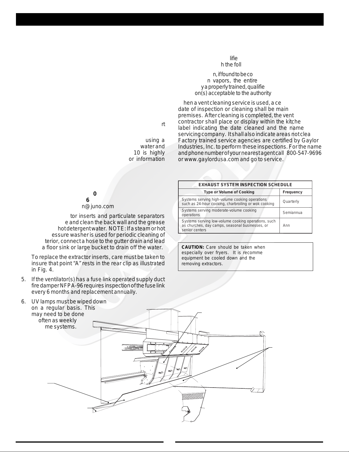
3. With the extractor inserts and particulate separators
removed, wipe and clean the back wall and the grease
gutter with hot detergent water. NOTE: If a steam or hot
water pressure washer is used for periodic cleaning of
the interior, connect a hose to the gutter drain and lead
it to a floor sink or large bucket to drain off the water.
4. To replace the extractor inserts, care must be taken to
insure that point “A” rests in the rear clip as illustrated
in Fig. 4.
5. If the ventilator(s) has a fuse link operated supply duct
fire damper NFPA-96 requires inspection of the fuse link
every 6 months and replacement annually.
6. UV lamps must be wiped down
on a regular basis. This
may need to be done
as often as weekly
on some systems.
INSPECTION AND CLEANING REQUIREMENTS
The 2001 edition of NFPA-96 (Standard for Ventilation Control
and Fire Protection of Commercial Cooking Operations)
require that hoods, ducts and exhaust fans be inspected by
a properly trained, qualified and certified company or person(s)
in accordance with the following table.
Upon inspection, if found to be contaminated with deposits from
grease-laden vapors, the entire exhaust system shall be
cleaned by a properly trained, qualified, and certified company
or person(s) acceptable to the authority having jurisdiction.
When a vent cleaning service is used, a certificate showing
date of inspection or cleaning shall be maintained on the
premises. After cleaning is completed, the vent cleaning
contractor shall place or display within the kitchen area a
label indicating the date cleaned and the name of the
servicing company. It shall also indicate areas not cleaned.
Factory trained service agencies are certified by Gaylord
Industries, Inc. to perform these inspections. For the name
and phone number of your nearest agent call 800-547-9696
or www.gaylordusa.com and go to service.
ELUDEHCSNOITCEPSNIMETSYSTSUAHXE
gnikooCfoemuloVroepyTycneuqerF
snoitarepognikoocemulov-hgihgnivressmetsyS
gnikoockowrogniliorbrahc,gnikoocruoh-42sahcus
snoitarepo
sretnecroines
CAUTION: Care should be taken when removing extractors,
especially over fryers. It is recommended that the cooking
equipment be cooled down and the fryers be covered prior to
removing extractors.
EXTRACTOR INSERTS
gnikoocemulov-etaredomgnivressmetsyS
hcus,snoitarepognikoocemulov-wolgnivressmetsyS
ro,sessenisublanosaes,spmacyad,sehcruhcsa
ylretrauQ
yllaunnaimeS
yllaunnA
MAIN GREASE
GUTTER
DURING CLEAN-UP PROCEDURES AT
THE END OF THE COOKING PERIOD
SPECIAL ATTENTION SHOULD BE
GIVEN TO WIPING CLEAN THE AIR
INLET OF THE VENITLATOR
DURING CLEAN-UP PROCEDURES
AT THE END OF THE COOKING
PERIOD THESE AREAS SHOULD
NORMALLY BE WIPED DOWN.
FIG. 4
8
UV PREVENTIVE MAINTENANCE
CERTIFIED SERVICE AGENT MAINTENACE WARNING!
Warning: Do NOT defeat the purpose of the interlocks during cleaning and maintenance!
These items will need to be performed by a trained and qualified
Certified Service Agency (CSA) on the same schedule as the
exhaust system inspection schedule described in NFPA-96 and
on the previous page in this tech manual. These tasks involve
potential exposure to high doses of UV light and live electrical
components. There is risk of injury to skin and eyes and in the case
of electrical shock, injury or death! For a list of CSAs go to
www.gaylordusa.com and go to "Service Agencies" for a list of
companies nearest you.
1. Inspection of the Lamps and Ballasts
a. Check the lamps for proper operation
1. Turn on the fan and look for the green "UV System
On" light on each hood section
a. If it is not on refer to "UV Troubleshooting",
pages 17, 18 and 20.
2. Open the UV Access door with the key
3. Turn on fan
4. Verify all of the Extractor Inserts are installed.
5. Depress the UV Access door safety switch
6. Check all indicator LEDs, 6 green and 3 red, to
ensure that they are all on. If they are not all on go
to "UV Troubleshooting", pages 17, 18 and 20.
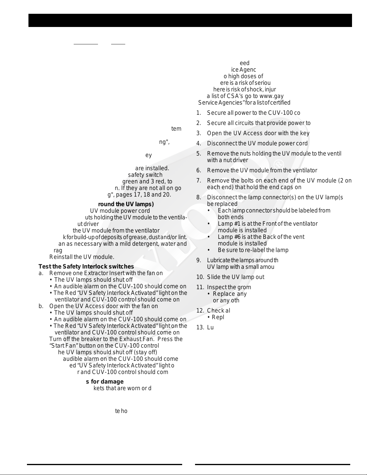
2. Inspect the Plenum (around the UV lamps)
a. Disconnect the UV module power cord
b. Remove the nuts holding the UV module to the ventila-
tor with a nut driver
c. Remove the UV module from the ventilator
d. Check for build-up of deposits of grease, dust and/or lint.
e. Clean as necessary with a mild detergent, water and
a rag
f. Reinstall the UV module.
3. Test the Safety Interlock switches
a. Remove one Extractor Insert with the fan on
• The UV lamps should shut off
• An audible alarm on the CUV-100 should come on
• The Red “UV Safety Interlock Activated” light on the
ventilator and CUV-100 control should come on
b. Open the UV Access door with the fan on
• The UV lamps should shut off
• An audible alarm on the CUV-100 should come on
• The Red “UV Safety Interlock Activated” light on the
ventilator and CUV-100 control should come on
c. Turn off the breaker to the Exhaust Fan. Press the
“Start Fan” button on the CUV-100 control
• The UV lamps should shut off (stay off)
• An audible alarm on the CUV-100 should come on
• The Red “UV Safety Interlock Activated” light on the
ventilator and CUV-100 control should come on
4. Check all gaskets for damage
a. Replace any gaskets that are worn or damaged
5. Check the Hour Meter
a. Record the hours
b. Determine the approximate hours between inspection
intervals.
c. Determine when the 8000-hour life of the lamps will
occur and inform the operator of the approximate date
when the lamps will need to be replaced
Replacing UV Lamps
Danger!
These items will need to be performed by a trained and qualified
Certified Service Agency (CSA). These tasks involve potential
exposure to high doses of UV light and live electrical components. There is a risk of serious injury to skin and eyes from UV
light. There is risk of shock, injury, and/or death from electrical.
For a list of CSA’s go to www.gaylordusa.com and go to the
“Service Agencies” for a list of certified companies nearest you.
1. Secure all power to the CUV-100 control
2. Secure all circuits that provide power to the UV lamps
3. Open the UV Access door with the key
4. Disconnect the UV module power cord
5. Remove the nuts holding the UV module to the ventilator
with a nut driver
6. Remove the UV module from the ventilator
7. Remove the bolts on each end of the UV module (2 on
each end) that hold the end caps on
8. Disconnect the lamp connector(s) on the UV lamp(s) to
be replaced
• Each lamp connector should be labeled from 1 to 6 on
both ends
• Lamp #1 is at the Front of the ventilator when the UV
module is installed
• Lamp #6 is at the Back of the ventilator when the UV
module is installed
• Be sure to re-label the lamp connectors if necessary
9. Lubricate the lamps around the grommets on each end of the
UV lamp with a small amount of G-510 or similar detergent
10. Slide the UV lamp out one end, CAREFULLY!
11. Inspect the grommets around the lamps
• Replace any grommets that show cracks, checking,
or any other damage
12. Check all wires for damage
• Replace any wires showing damage
13. Lubricate each of the new UV lamp(s) before installing
with a small amount of G-510 or similar detergent
14. Re-connect the lamp connectors on both ends of the UV lamps
• Each lamp connector should be labeled from 1 to 6) on
both ends
• Lamp #1 is at the Front of the ventilator when the UV
module is installed
• Lamp #6 is at the Back of the ventilator when the UV
module is installed
15. Re-install the UV module end caps and torque the bolts
to 7-10 in-lbs.
16. Re-install the UV module in the ventilator
17. Tighten all nuts holding the UV module to the ventilator
18. Re-connect the UV module power cord
19. Check for proper operation of UV lamps
9
SAFETY CONCERNS WITH UVC
As with many types of technology if it is not used properly and/
or proper precautions are not taken there is the potential for
injury or harm. This is especially true with UVC light due to
the fact that it does not physically hurt at the time of exposure.
While UVC is very effective at breaking down grease molecules, direct exposure to large amounts is harmful to skin
and eyes. The amount of UVC generated in these hoods is
greater than that what results from direct exposure to the sun.
Under no circumstances is it acceptable to view the lighted
lamps without proper eye protection or expose bare skin
directly to the light. All interlocks and safety precautions
called for in this manual must be followed to avoid the potential
for harm to service personnel and/or operators. In addition,
only trained and authorized personnel may perform some
maintenance See previous page for details.
Personal Protective Equipment
1. Eye protection that prevents 100% of UVC being trans-
mitted through the lens must be worn at all times when
performing service work on any Ultima Vent that is
energized and/or has the potential to be energized and
expose personnel to UVC light.
2. Whenever service work is performed it is recommended
that long sleeve pants and shirts be worn to minimize the
potential for inadvertent exposure of the skin to UVC.
Safety Interlocks
This product comes equipped with the following sensors to
verify that all access doors are in place and that the exhaust
fan is running:
1. Mechanical door switch on the UV Access door to ensure
that the door is closed
2. Gaylord Extractor Monitor (GEM) that ensures all of the
Extractor Inserts are installed.
3. Air Pressure switch to verify air flow and exhaust fan
operation
All of these devices must be working and/or adjusted properly
in order for the system to operate properly.
10
START-UP PROCEDURES
Before using the Ultima Vent a complete and thorough start-up of the Ultima Vent system must be performed by a qualified, and
authorized service technician. Because of this the UV modules will be shipped separate from the hood to an Certified Service
Agent(CSA). Contact Gaylord Industries to arrange for this service. It is normally included in the purchase price of the hoods.
Start-up requirements and activities
At the time of shipment a Certified Service Agent (CSA)will be
selected to perform the installation of the UV modules and the
start-up for the Ultima Vent system.
The Service agent should confirm the following prior to going
to the job site:
1. The Exhaust and Supply fan(s) are connected to the
ductwork
2. The fans have electricity and will run
3. The CUV-100 control panel is mounted and has the
following:
a. Power to the CUV -100
b. All necessary electrical connections between the CUV-
100 and the hood, surface fire protection system, and
fans.
4. All lighting wiring is connected to the hoods and light
switch
5. There is a 120 Volt, 20 Amp power circuit going to each
hood section, for UV lamps
6. Any personnel (Fire Marshal, owners rep., GC, FP
contractor, air balancer, etc) required to witness the start
up would need to be notified of time and date for start-up.
Field Start up directions
Allow about 1 hour per hood section, at the job site, for the
activities described below:
1. Check for power to the CUV-100 and wiring between the
CU V-100 and the hoods
2. Check that all Extractor Inserts are properly installed
3. Start the exhaust fan by turning the CU V-100 control on.
Both supply and exhaust fans should start. The green “UV
System On ” light should be on. If this does not occur refer
to "UV Troubleshooting" on pages 17, 18 and 20.
4. Turn CUV-100 control off. This will shut off the fans.
5. Open the UV Access door and remove the blank plate
from the UV light opening.
6. Install the UV light modules in the hood. Connect the plug
on the UV module to the hood.
7. Start the exhaust fan and check for the green “UV
System On” light at the hood(s) and control panel. Make
sure that all access doors are closed.
8. Check the air velocity at the inlet slot
9. Record the data on the start up form. Determine the
correct inlet slot velocity and record that in the design
velocity location. Then determine the percentage of design that the actual air velocity represents
11. Remove an Extractor Insert
a. The red “Safety Interlock Activated” lamp should come on
and an audible alarm sound.
12. Check the UV Access door interlock
a. Open the UV Access door with the fan on.The red
“Safety Interlock Activated” lamp should come on and
an audible alarm sound.
Caution: Before any Fire tests are performed, check with
the building superintendent to see if the Surface Fire
Protection system is wired to the building alarm, monitor-
ing system, and/or fire department.
13. If the FP contractor is there have them trip the micro
switches on the FP system to verify that the Exhaust
Fan(s) starts and supply Fan(s) shut off.
14. Once all is working correctly demonstrate the following to
the end user
a. If the hood is interlocked with the FP system. Have the
FP contractor test it and confirm that the External fire
mode works properly.
b. Instruct them that if for any reason they can see the UV
light directly they must shut off the hood immediately
and call a CSA.
c. Check for proper damper operation if this hood has a
damper
d. How to remove, clean and replace the Extractor Inserts
e. That they need to perform the required end user main-
tenance described in the tech manual and hire CSA to
perform the UV maintenance as described in the tech
manual and have the duct system inspected/or cleaned
per the requirements of NFPA-96.
f. The frequency will need to be adjusted based on the
type, amount and duration of cooking done at this site.
q. Fill out the start up form completely with comments
r. Notify the Dealer/customer if the air volumes are more
than 5% low or 10% high and give the dealer and GC
a copy of the Start-up report.
g. Send a copy of the Start-up report to Gaylord and keep
a copy for your records.
11

MEASURING INLET SLOT VELOCITY
MEASURING INLET SLOT VELOCITY
Smoke capture and grease extraction efficiency are dependent upon the proper air velocity at the inlet slot of the
ventilator.The required average slot velocities are shown
on the “Air Velocity Chart” below. If the slot velocity is
below the required average, the exhaust fan must be
adjusted accordingly.
NOTE: The height of the inlet slot can vary depending
upon the design of the ventilator. It is, therefore, important
to first measure the inlet slot and compare it to the chart
below to determine the required average inlet slot velocity. The designed CFM per lineal foot is related to the
velocity as shown on the chart below. The total CFM for
the ventilator can be found on the ventilator nameplate.
(See Figure 6).
TRAHCYTICOLEVRIA
SEIRES"SD"TPECXESEIRES"2XG"LLAROF
motsuCtuohtiW
lanimoN
thgieH
fo
tolStelnI
dengiseD
repMFC
.tFlaeniL
selffaBriA
.niM mumitpO .xaM
telnIegarevA
)MPF(yticoleVtolS
dengiseD
repMFC
.tFlaeniL
motsuChtiW
selffaBriA
.niM mumitpO .xaM
telnIegarevA
)MPF(yticoleVtolS
"3
"4
052
)dtS(
072
582
003
004
)lnE(
0031
0631
5241
5641
0961
0541
051
0831
0051
5341
5751
0051
5261
5451
0781
0871
067
061
097
071
018
081
548
052
0401
088
008
078
038
009
558
539
088
0511
5901
*SROTALITNEVSEIRES"SD"ROF
rePMFCdengiseD
.tFlaeniL
latoT
tnorF
htoB
tolS
stolS
003
051
004
052
raeR
tolS
051
051
.niM mumitpO .xaM
067
5731
tolStnorF
088
008
0251
0541
telnIegarevAderiuqeR
)MPF(yticoleVtolS
tolSraeR
.niM mumitpO .xaM
595
526
595
526
556
556
Air velocity readings less than what is specified on the “Air
Velocity Chart” may allow smoke and grease to escape
the confines of the ventilator and/or reduce grease extrac-
tion efficiency. This can result in grease deposits which
lead to sanitation problems or fire hazards if left uncorrected. If air velocity readings are higher than those
specified, it will require more energy to operate the
exhaust fan and excessive noise levels will result. Higher
or lower velocities than the required average will normally
put the entire heating and ventilating system out of balance. When measuring the air velocity it is very important
to take an average reading across the inlet slot plane as
described on Page 13. Positioning the sensing head
incorrectly will give velocity readings that cannot be compared to the “Air Velocity Chart”.
12

FIG. 5A
FIG. 5B
MEASURING INLET SLOT VELOCITY
The standard instrument used for measuring the inlet velocities on a Gaylord
Ventilator is a Pacer, Model DA40 or DA4000 Digital Anemometer. This
instrument is the easiest, most accurate and the best suited for measuring
ventilator inlet slot velocities. To take accurate air velocity readings, follow
the instructions below.
Instructions
1. It is first necessary to determine if the ventilator includes Custom Air baffles
as shown in Fig. 5B. If shop drawings are available, and if equipped, the
custom baffles and their location will be noted on the front elevation. If not
available, to determine if Custom Air baffles are provided run your hand along
the bottom inlet slot and feel for the Custom Air baffle as illustrated in Fig. 5B.
2. If the ventilator includes Custom Air baffles, it will be necessary to take two
sets of readings - one for the section of ventilator that includes Custom Air baffles
and one where it does not.
3. Attached the sensing head guide bracket, Gaylord Part Number 18408, to
the sensing head.
4. Attach the cable from the sensing head to the meter and the handle
sections to the sensing head.
5. Place the sensing head guide bracket against the lower lip of the inlet slot
as illustrated.
6. Using the 16 second averaging feature on the meter, slide the sensing head along
the slot, back and forth, for a 3'-0" to 4'-0" distance, and record the velocity at the end
of the 16 second mark. Continue this process for the full length of the ventilator.
Important Note: If the ventilator includes custom air baffles as illustrated in Fig.
5B, always take separate readings on the section of the ventilator that includes
custom air from the section that does not have the baffles. Non custom air and
custom air readings must be recorded separately. Do not average them together.
Important Note: On the rear slot of a Model BDL-DS Series, do not use the
guide bracket. Refer to Figure 5C.
7. Record the velocity (fpm) on the start up inspection report form. A sample
report form, which can be photocopied, is provided on page 16.
8. The designed, or optimum velocity, is noted on the shop drawings and
the Air Velocity Chart on page 12. Two velocities will be noted if the ventilator
includes custom air baffles.
9. Compare the recorded air velocity to the designed air velocity shown on the
shop drawings or the Air Velocity Chart on page 12. The recorded velocity may
be slightly lower or higher providing that it is within the minimum and maximum
range as shown on the Air Velocity Chart .
If the air velocity is outside the minimum/maximum range, the performance of
the ventilator will be affected and therefore the exhaust fan must be adjusted.
FIG. 5C
CROSS SECTION OF TYPICAL
VENTILATOR INLET SLOTS
13

LISTED
370Y
EXHAUST HOOD WITH
EXHAUST DAMPER
THIS EXHAUST HOOD HAS BEEN TESTED
TO STANDARD UL 710 "EXHAUST HOODS
FOR COMMERCIAL COOKING
EQUIPMENT"
THIS EXHAUST HOOD IS LISTED UNDER UL
FILE NUMBER 11403
THIS EXHAUST HOOD MEETS ALL REQUIRE-
MENTS OF THE LATEST EDITION OF NFPA-
96 AND THE IMC (INTERNATIONAL MECHANI-
CAL CODE)
o SUPPLIED WITH FACTORY INSTALLED UL LISTED
GRINNELL CORP. EA-1, 1/4" ORIFICE, 65 DEGREE
DEFLECTOR SPRINKLER(S) FOR THE PROTEC-
TION OF UNLIMITED LENGTH OF GREASE DUCT
HAVING A MAXIMUM DUCT PERIMETER OF 50
INCHES PER SPRINKLER. CONNECT TO NFPA 13
SPRINKLER SYSTEM WATER SUPPLY ONLY.
PATENT PENDING
MEASURING INLET SLOT VELOCITY
ENGINEERING DATA
1. MINIMUM TOTAL EXHAUST
VOLUME FOR THIS HOOD SECTION
2. MAXIMUM TOTAL SUPPLY
VOLUME FOR THIS HOOD SECTION
3. EXHAUST STATIC PRESSURE AT
DUCT COLLAR
4. SUPPLY STATIC PRESSURE AT
DUCT COLLAR
5. THIS HOOD SECTION SUITABLE FOR APPLIANCES WITH MAXIMUM COOKING
SURFACE TEMPERATURE OF:
˚F FOR LINEAL FT. OF HOOD
˚F FOR LINEAL FT. OF HOOD
6. REFER TO GAYLORD VENTILATOR TECHNICAL MANUAL FOR INLET
VELOCITY REQUIREMENTS AND METHOD OF CHECKING VELOCITY
7. ELECTRICAL RATING OF LIGHT FIXTURES: 120 VOLT, 60 HZ. OR 220 VOLT,
50 HZ. OVERALL RATING - 12 AMPS OR LESS
8. ON "GX2" and "PG" SERIES VENTILATORS EQUIPPED WITH FUSE LINK
OPERATED EXHAUST FIRE DAMPER USE ONLY 280˚ F , RATED 30 LBS. MIN. UL
LISTED FUSIBLE LINK FOR REPLACEMENT
9
. IF HOOD IS EQUIPPED WITH INTEGRAL MAKE-UP AIR WITH FUSE LINK OPER-
ATED FIRE DAMPER USE ONLY 165˚ F, RATED 30 LBS. MIN. UL LISTED FUSIBLE
LINKS FOR REPLACEMENT
10.DUCTWORK AND EXHAUST FAN
A. STATIC PRESSURE OF DUCT SYSTEM MUST BE ADDED TO VENTILATOR
STATIC FOR TOTAL SYSTEM STATIC
B. ALL DUCTWORK MUST BE WELDED LIQUIDTIGHT
HOOD MOUNTING REQUIREMENTS
MINIMUM DISTANCE FROM COOKING SURFACE TO FRONT
LOWER EDGE OF HOOD
MAXIMUM DISTANCE FROM COOKING SURFACE TO FRONT
LOWER EDGE OF HOOD
MINIMUM OVERHANG FROM FRONT OF HOOD CAVITY TO
FRONT OF COOKING SURFACE
MAXIMUM SETBACK FROM FRONT OF HOOD CAVITY TO
FRONT OF COOKING SURFACE
MINIMUM OVERHANG FROM SIDE OF HOOD TO EDGE OF
COOKING SURFACE
SERIAL NO:
MODEL NO:
C.F.M.
C.F.M.
W.G.
W.G.
TOTAL EXHAUST CFM HERE
TOTAL SUPPLY CFM HERE
FIGURE 6
The total required exhaust volume can be
found stamped on the UL nameplate located
on each hood section.
WORLD HEADQUARTERS
GAYLORD INDUSTRIES, INC.
10900 S.W. AVERY STREET
TUALATIN, OR 97062-8549 USA
PHONE: 1-503-691-2010
FAX: 1-503-692-6048
EMAIL: info@gaylordusa.com
UL-GX2/PG 1000
MAINTENANCE INSTRUCTIONS
1. REMOVE, INSPECT AND CLEAN FILTERS OR GAYLORD EXTRACTOR
CARTRIDGES AS REQUIRED
2. REMOVE AND EMPTY GREASE CUP AS REQUIRED
3. CAUTION - DO NOT OPERATE VENTILATOR WITHOUT FILTERS OR EXTRACTOR
CARTRIDGES IN PLACE
4. REPLACE FILTERS IN "PG" SERIES ONLY WITH UL CLASSIFIED GREASE FILTERS.
IN "PGX" AND "GX2" SERIES REPLACE WITH GAYLORD INDUSTRIES
EXTRACTOR CARTRIDGES.
5. IF THE VENTILATOR(S) HAS A FUSE LINK OPERATED EXHAUST OR SUPPLY
DUCT FIRE DAMPER THE NATIONAL FIRE PROTECTION ASSOCIATION'S
PAMPHLET NFPA-96 REQUIRES INSPECTION OF THE FUSE LINK EVERY 6
MONTHS AND REPLACED ANNUALLY. REFER TO THE GAYLORD VENTILATOR
TECHNICAL MANUAL FOR DETAILS.
14

.1tonsirotalitneV-ssoLekomS
TROUBLE-SHOOTING
MOTPMYSMELBORPELBISSOPNOITCAEVITCERROC
SSOLEKOMS
.ylreporpgnitsuahxe
.A
.gniwollofehtkcehcwolsiyticolev
yticolevriaegarevA-yticolevriawoL
.1
niebdluohstolsyrtneriaehthguorht
notrahCyticoleVriAehthtiwecnadrocca
.2
gnirusaemfodohtemreporproF.21egap
ehtfI.31egapotrefer,yticolevriaeht
.3
.naftsuahxeehtnotlebgnippilsronekorB
.leehwnaftsuahxeehtfonoitatorreporP
reviledtsumnaf(naftsuahxefoezisreporP
.)gnitaretalpeman
.4
.5
.B
.C
.D
.riapu-ekametauqedanI
nwostievahtsumrotalitneVdrolyaGehT
.1
hcus,tsuahxerehtoondnametsystsuahxe
.tiotnideitebdluohs,sdoohrehsawhsidsa
.sresuffidriapu-ekamdecalpylreporpmI
.1
.2
.3
.1
epytoneraIIfI.nideitsmetsysrotalitnev
.devomerebtsumyehtos
.rotalitnev
.aeranehctik
.ssolekomsnignitluser
.smetsystsuahxenehctik
.nepotfellenapnoitcepsnikrowtcuD
.noitisopreporpnironepotonrepmaD
erehttahtyfirevdnametsystcudtcepsnI
lliwrotalitnevehttadetceridriapu-ekaM
riaehtgnitpursidstfardssorcetaercylekil
srevuolehttsujdA.rotalitnevehtotniwolf
ehtmorfyawariapu-ekamehttceridot
hguorhtdereviledebdluohsriapu-ekaM
sretsigerrosresuffiddetarofrephtgnellluf
ehttuohguorhtdetubirtsidthgiehgniliecta
ehtraendetacolsretsigerriapu-ekaM
otdetsujdaebdluohssrevuoleht,rotalitnev
.rotalitnevehtmorfyawariaehttcerid
ehttariapu-ekamgnicrofrognitceriD
stfardssorcsetaercyllacipytrotalitnev
rofdeilppusebtsumriapu-ekaM
llahguorhtdetsuahxeriafotnemecalper
.E
NOITCARTXEESAERG
.1.noitcartxEesaerGrooP.ArotalitneVseireS"VU-2XG"drolyaGehT
.2
.saeratnecajdamorf
.egrahcsidnaftsuahxE
.wolsiemulov
.1
.devomer
.2
.dednemmocer
.1nodebircsedsayticolevtolstelniehtkcehC
dnatsud,esaergehtfo%99otpustcartxe
gnissapmaertsriaehtmorfselcitraptnil
deniatniamdnadetareponehw,tihguorht
fI.snoitacificepsngisedhtiwecnadroccani
tonsirotalitnevehttahtsraeppati
tsuahxeehtyllacipyt,ylreporpgnitcartxe
.deriuqersadeepsnafehtecuder
ot%57tahtsi"bmuhtfoelur"larenegA
,hserfebdluohsriatnemecalperehtfo%08
thguorbria)deloocrodetaeh(,denoitidnoc
gniniamerehthtiw,aeranehctikehtotni
nehctikehtotniwolfotdewolla%52ot%02
ehtrevoneercsonebdluohserehT
ebdluohsti,dnuofsienofI.egrahcsid
ebtondluohsegrahcsidfonoitceridehT
drawnwodronsdniwgniliaverpehtotni
ylhgihsiegrahcsidlacitrevA.foorehtotno
tonsiyticolevehtfI.31hguorht21segap
roesaercni,egnarderiuqerehtnihtiw
15

.1ehtnodenrutsihctiwsnafehtnehwfI
TROUBLE-SHOOTING
MOTPMYSMELBORPELBISSOPNOITCAEVITCERROC
NAFTSUAHXE
.noemoctonseodnaftsuahxe
.A
.B
.deppirt
Iepyt)citamotuA/nOsdnaH(AOHnaf
noitisopcitamotuaehtmorf
retratscitengamnorotcetorpdaolrevO
.1
.retnecdnammoc
.1
eht,desusihctiwsretratscitengam
devomneebevahyamhctiwsrotceles
.noitisopcitamotuaeht
ehtnonottub"teseR"ehthsuP
hsupehtdnaretratscitengam
ehtnonottub"naFtratS"eht
otrotcelesnrutdnahctiwskcehC
.C
.D
.deppirtrekaerbtiucricnaftsuahxE
.1
nahtiwdeppiuqesimetsysehtfI
.1
,naftsuahxeehtrofhctiwstcennocsid
.tuonwolbevahyamsesufroesufa
rekaerbtiucrictes-eR
dnasesuffoytiunitnockcehC
.yrassecenfiecalper
16

TROUBLESHOOTING UV SYSTEM
Danger!
These items will need to be performed by a trained, qualified
and Certified Service Agency (CSA). These tasks involve
potential exposure to UV light and live electrical components.
SYMPTOM POSSIBLE PROBLEM CORRECTIVE ACTION
1. After CUV-100 is turned on, fan starts:
* Yellow "UV Lamp Failure" light is on
* Audible Alarm is on
A. No power to t he vent i l ator section(s). 1. Check for 120 Volts on between L1 & L 2 at
There is risk of injury to skin and eyes and in the case of
electrical shock, injury or death! For a list of CSA’s Go to
www.gaylordusa.com and go to Service for a list of companies nearest you.
ventilator. If there is no power at L1 and L2
coming to this ventilator section identify the
circuit breaker, correc t and re-check.
B. Loose wire between CUV-100 and
ventilator.
C. No s tart signal from CUV-100 to ventilator
section(s).
D. Fuse i s blown on UV Controller in ventilator. 1. Check Fuse F2 on t he UV Controller.
E. The contactor has failed (CR20). 1. If there is power to L1 and L2. Check for
F. Green "UV S ystem On" light has failed. 1. Check for power to the Green " UV System
2. * Yellow "UV Lamp Failure" light is on
* Green "UV System On" light i s on
* Audible Alarm is on 2. With fan running, Open UV Access door
3. Yellow "UV Lamp Failure" light is on
ONLY at CUV-100 control NOT on any of
the ventilator sections.
A. UV Lamp or UV Ballast has failed. 1. Identify ventilator section with Yellow “UV
B. The contacts on the UV Controller have
closed permanently.
C. Relay CR22 i n ventilator has failed. 1. With Exhaust fan on, check for continuity
D. Relay CR12 i n CUV-100 has failed. 1. Check CR12 for proper operation, replace if
A. Yellow "UV Lamp Failure" light on ventilator
has failed.
1. Check for 120 Volts between 6U and 5U in
the ventilator. If none c hec k CR13 in the
CUV-100 for power and operation. If there
is power there check for 120 volts between
1U and 5U. If there is power, check t he
green lamps for proper operation.
1. Check Fuse F7 in CUV-100.
power to the contactor coil (CR20). Correct
lack of power.
On" light
a. If no power, Check the circ ui t and
locate problem.
b. If there is power the Green "UV
System On" light has failed and needs
to be replaced.
Lamp Failure” light on.
3. Depress the UV Access door switch and
identify which Lamp/Ball ast’s green light is
not on
4. Switch the pin connector on that Ballast with
another Ballast and check agai n
a. If the alternate Ball ast’s green light
comes on, replace the Ballast
b. If the alternate Ball ast’s green light
does not come on, replace the Lamp
1. Check for continuity between 2A and 3A in
ventilator. If there is continuity AND all of
the UV lamps are working, (6) green a nd
(3) red lights on at the UV Control l e r, the UV
Controller needs to be replaced.
across the N.O. cont acts of CR22 in the
ventilator. If there is continuity AND all of
the UV lamps are working, repl ace relay
CR22.
necessary.
1. Check the Yellow "UV Lamp Failure" li ght
and see if it is receiving power.
a. If no, the problem i s in the wiring.
Locate and correct the problem
b. If yes, replace the l amp.
17

SYMPTOM POSSIBLE PROBLEM CORRECTIVE ACTION
4. During t he l amp inspection one of the UV
Controllers does not have (6) Green & (3)
Red indicator lights on and there is no
Yellow "UV Lamp Failure” lamp on.
5. Red “UV Safety Interlock Activated” light
on AND Audible Alarm on.
TROUBLESHOOTING UV SYSTEM
A. The Yellow "UV Lamp Failure" light has
failed.
B. The Connection from the 2A on the UV
Controller and the terminal blocks is broken
or loose.
C. The contacts on the UV Controller has failed
to close.
A. UV Access Door Switch (DS) has failed or
needs to adjusted.
B. An Extractor Insert has been removed or is
not properly inserted
C. Gaylord E xtractor Monitor (GEM) has failed 1. Check for continuity between G1 and G2.
1. Check the Yellow "UV Lamp Failure" light and
see if it is receiving power.
a. If no, the problem i s in the wiring.
Locate and correct the problem
b. If yes, replace the l amp.
2. If the Yellow "UV Lamp Failure" light has power,
replace the light.
1. It may be the contacts on the ballast
a. Check for power coming out of
terminal 2A in the ventilator
1. Check for continuity between 2A and 3A at
ventilator. If a UV lamp has failed and there are
(6) green and (3) red lights on on the UV
Controller, the UV Controller needs t o be
replaced.
1. Check for continuity between D1 & D2 and D3 &
D4 with the door switches depressed. I f there is
2. If there is continuity check the UV Pressure
Switch and UV Proximity S wit ch.
1 Remove and re-insert Extrac t or Insert
6. Pres sing "Cancel Audible Alarm" button
on CUV-100 does NOT silence alarm.
D. Pressure switch (PS) has failed or needs
adjusting.
D. Pi l ot tube to sense air pressure is plugged. 1. Check the Pi tot tube for blockage. Clear and
E. Rel ay CR23 i n ventilator has failed. 1. With Exhaust fan on, close Inspection (wash
F. Relay CR11 i n CUV -100 has failed. 1. Check CR11 for proper operation, replace if
A. Ti ming Relay TR1 in CUV-100 is not set
correctly or has failed.
B. Relay CR10 in CUV-100 has failed. 1. Check Yellow “UV Lamp Failu re” l i ghts. Identify
1. Check for power to the UV Pressure Switch with
the fan on.
2. Check for continuity between P1 and P2. It
should be closed with the fan on
3. With the fan on turn the pressure switch
adjustment screw Clockwise until there is
continuity between P1 and P2.
4. If there is continuity, check the UV Access Door
Switch and the UV Proximit y Switch
check again.
2. Check all tubing connections to make sure they
are tight.
access) doors and depress UV A ccess Door
switches. Check for c ontinuity across the N.O.
contacts of CR23 in the ventilator. If there is
continuity, replace rel ay CR23.
necessary.
1. Check TR1 for proper operation and verify it is
set for 1 second.
which ventilator section(s) has the same light
on. If it is on, s ee above f or solution.
7. Audi bl e al arm comes on for
approximately 60 Seconds each day
when "Start Fan" button is press ed.
A. Ti ming Relay TR2 in CUV-100 is not set
correctly or has failed.
18
1. Check TR2 for proper operation and verify it is
set for 60 seconds.

TROUBLESHOOTING
CUV-100 TERMINAL VOLTAGES
TERMINAL DESCRIPTION FAN OFF FAN ON EXT. FIRE
TROUBLESHOOTING UV SYSTEM
L1 Main Power Connection : Hot 120 VAC 120 VAC 120 VAC
L2 Main Power Connection : Neutral
1 Output to Supply Fan Motor Starter 0 VAC 120 VAC 0 VAC
5 120 VAC Neutral Leg
8 Output to Exhaust Fan Motor Starter 0 VAC 120 VAC 120 VAC
FS1
FS2
FS3
FS4
1U Input from "UV System On" (Green) 0 VAC * *
2U Input from "UV Lamp Failure" (Amber) 0 VAC * *
3U
5U 120 VAC Neutral Leg
6U Output to UV Lamps Contactor 0 VAC 120 VAC 120 VAC
Supply Fan Fire Switch Connections
N.C. Contacts
Exhaust Fan Fire Switch Connections
N.O. Contacts
Input from "UV Safety Interlock Activated"
(Red)
Closed Closed Open
Open Open Closed
0 VAC * *
Common
High Voltage Common
High Voltage Common
120 VAC - when UV lights should be on
0 VAC - when UV lights should be off
(Refer to UV Status Light Chart on following page)
19

TROUBLESHOOTING
g
UV Status Lights
UV Status Li
Green
UV System Mode
All UV Lamps ON "Normal"
One or more UV Lamps
not working
UV Module un-plugged
No power to the UV Module
(All Doors closed)
UV Access Door Open
Inspection (Wash Access) Door
Open
Exhaust Fan is not running at full
speed
The UV System is designed to run whenever the Exhaust Fan is running.
The UV Status Lights will only activate when the UV System should be on. (Exhaust Fan Running)
"UV System On" (Green) Light
* ON when UV System is energized
"UV Lamp Failure" (Yellow) Light
* ON whenever UV System is energized and one or more of the UV Lamps and/or UV
Ballasts have failed or if the UV Lamps do not have power
* The rest of the UV Lamps will continue to run - call a Certified Service Agent for service
"UV System On"
light on
X
XX
XX
Yellow
"UV Lamp Failure"
light on
X
hts
Red
"UV Safety Interlock
Activated"
light on
X
X
X
"UV Safety Interlock Activated" (Red) Light
* ON when a UV Access Door is open
* ON when a Inspection (Wash Access) Door is open
* ON when UV Pressure Switch detects that the static pressure is too low
* All UV Lamps will shut off immediately
, whenever any of the above happens
UV Controller Status Lights
Normal Operation
• 3 Red lights on
• 6 Green lights on
UV Lamp Failure
• "Summary Alarm" light is OFF
• The Green light for the UV Lamp/Ballast
that has failed will be OFF
NOTE:
• UV Lamps are numbered 1 to 6 from
Front-to-Back
• UV Ballasts are numbered 1 to 6 from
Left-to-Right
• The TOP of the UV Module has several
long slots cut-out for ventilation
20

MODEL CUV-100 CONTROL CABINET
1
2
3
4
5
6
7
8
9
PC.
NO.
1 UV Status Light Label 19397
2 Indicator Light - Red 19162
3 Indicator Light - Yellow 12510
4 Indicator Light - Green 12512
5 Cancel Switch 19076
6 Hour Meter 19164
7 C-150 Label 18644
8 C-150 Switch 18314
DESCRIPTION
GAYLORD PART
NO.
21
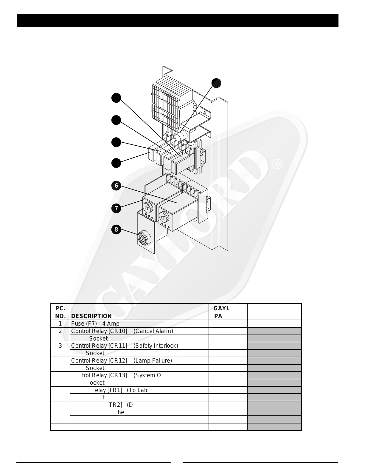
MODEL CUV-100 SERIES CONTROL
1
2
3
4
5
6
7
8
PC.
NO. DESCRIPTION
1 Fuse (F7) - 4 Amp 10039 BUSS AGC-4
2 Control Relay [CR10] (Cancel Alarm) 11399
Socket 11413
3 Control Relay [CR11] (Safety Interlock) 11399
Socket 11413
4 Control Relay [CR12] (Lamp Failure) 11399
Socket 11413
5 Control Relay [CR13] (System On) 11399
Socket 11413
6 Timing Relay [TR1] (To Latch the Audible Alarm) 30375
Socket 30376
Timing Relay [TR2] (Delays Audible Alarm until
7
Exhaust Fan reaches operating speed)
Socket 30376
8 Sonalert 30528
GAYLORD
PART NO. MFG PART NO.
30375
22

PARTS LIST
DROLYAG
.ONTRAP
09857
19857
69857
79857
29857
39857
49857
59857
12301
32301
00481
NOITPIRCSEDNOITARTSULLI
)lagartsAtfeL(tresnIrotcartxE"2/1-51
lagartsAtfeL(tresnIrotcartxE"2/1-91
)srotcartxE.tF.niL/MFC052-dtS(
tresnIrotcartxE"2/1-51lagartsAtfeL(
tresnIrotcartxE"2/1-91lagartsAtfeL(
)srotcartxE.tF.niL/MFC004-lnE(
)lagartsAthgiR(tresnIrotcartxE"2/1-51
lagartsAthgiR(tresnIrotcartxE"2/1-91
)srotcartxE.tF.niL/MFC052-dtS(
tresnIrotcartxE"2/1-51lagartsAthgiR(
tresnIrotcartxE"2/1-91lagartsAthgiR(
)srotcartxE.tF.niL/MFC004-lnE(
stcuDylppuSrofkniLesuFF°561
stcuDtsuahxErofkniLesuFF°082
looTlavomeRrotcartxE
)srotcartxE.tF.niL/MFC004+052roF(
91101
11231
01231
11101
21101
57031
15391
ebolGthgiL
emarF&sneLthgiLtnecsednacnI
reniateR&sneLthgiLdesseceR"21x"21
emarF&sneLthgiLtnecseroulF
reniateR&sneLthgiLdesseceR.tF2
reniateR&sneLthgiLdesseceR.tF3
reniateR&sneLthgiLdesseceR.tF4
puCesaerG "4x"6x"4/1-3
ctaLrooDsseccAVU h
56391
hctiwSerusserPVU
23

UV MODULE PARTS
)
1
2
16
3
15
11
4
14
5
8
10
9
NOTE:
7
• UV Lamps are numbered 1 to 6 from Front-to-Back
• UV Ballasts are numbered 1 to 6 from Left-to-Right
• The TOP of the UV Module has several long slots cut-out
for ventilation
PC.
NO.
1 UV Light Grommet 19312
UV Lamp - 3 Foot 19296
2
UV Lamp - 5 Foot 19301
3 UV Lamp Holder 19313
4 1/4" Nylon Washer 19357
5 1/4"-20 x 2-1/2" Bolt 19356
6 1/4" Retaining Clip (Not Shown) 19358
7 UV Light Ballast 19237
8 Circuit Board Stand-off 19308
9 Fuse (F1) - 500mAmp UV Controller 18153
10 Fuse (F2) - 8 Amp UV Controller - Main 19424
UV Light Controller (includes status lights circuit
11
board - not shown)
12 UV Wiring Harness (Not Shown) 19349
UV-3 Gasket Kit
1) UV-3 Frame Gasket
2) UV-3 Access Door Gasket
3) Left & Right UV Chase Gaskets for End Caps
Plenum Access Gasket
4
13
UV-5 Gasket Kit - includes:
1) UV-5 Frame Gasket
2) UV-5 Access Door Gasket
3) Left & Right UV Chase Gaskets for End Caps
4) Plenum Acce ss Gasket
DESCRIPTION
- includes:
GAYLORD
PART NO.
19236
75878
75879
PC.
NO.
14 UV Chase Cover - Left 19290
UV-3 Ballast Cover 19300
15
UV-5 Ballast Cover 19305
16 UV Chase Cover - Right 19291
UV-3 Light Module Frame - ALL Sheet Metal parts
* Includes: Bolts, Washers, & Retaing Clip
* Does NOT include Gaskets or Grommets
17
UV-5 Light Module Frame - ALL Sheet Metal parts
* Includes: Bolts, Washers, & Retaing Clip
* Does NOT include Gaskets or Grommets
UV-3 Light Module (Complete)
- Complete with UV Controller, Ballasts, & UV Lamps, UV
Wiring Harness, & Frame Gask et s
18
UV-5 Light Module (Complete)
- Complete with UV Controller, Ballasts, & UV Lamps, UV
Wiring Harness, & Frame Gask et s
DESCRIPTION
GAYLORD
PART NO.
19307
19306
75876
75877
24
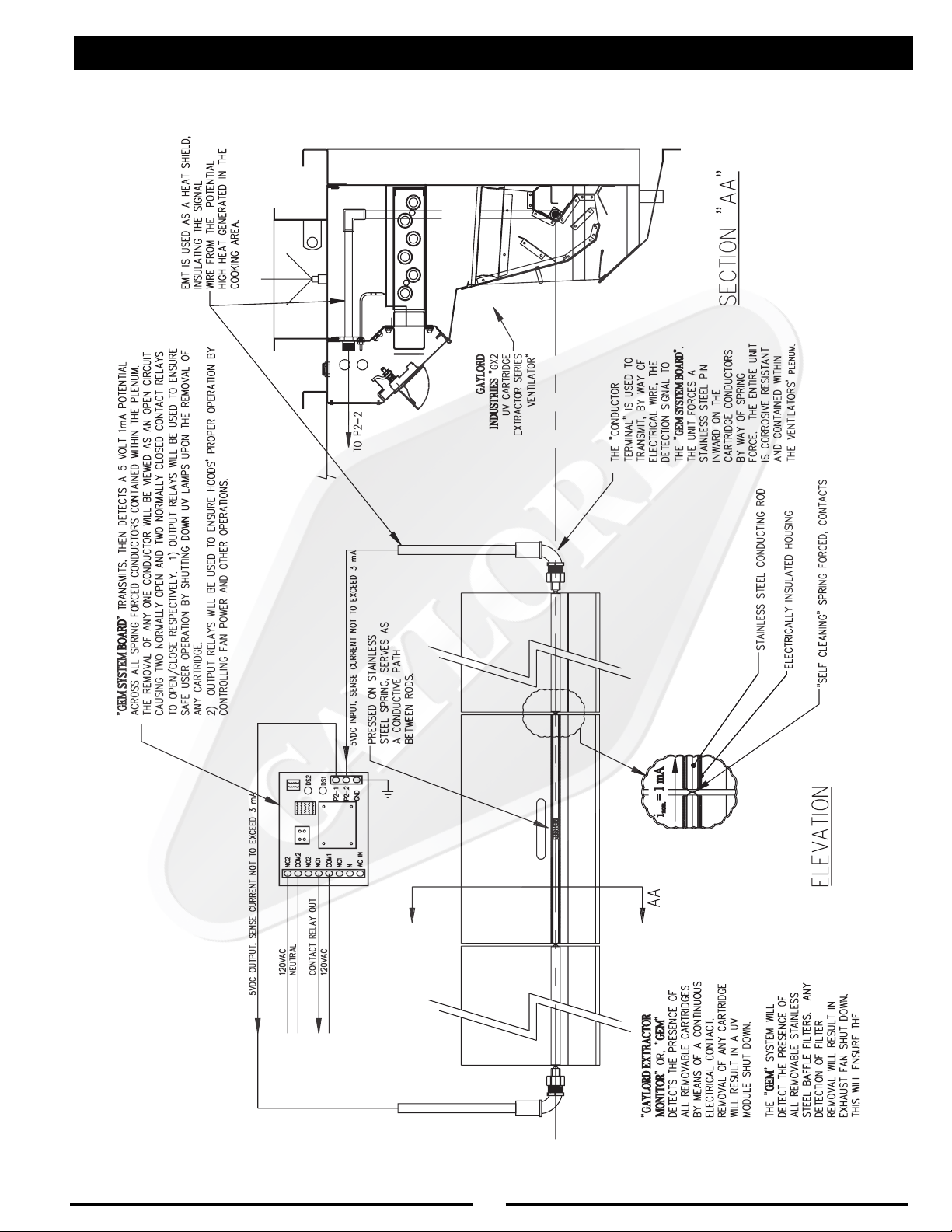
GEM SYSTEM DIAGRAM
25

UV HOOD WIRING
g
PC.
NO.
CR20 Contactor 30529
CR21,
Control Relay 11399
23,24
Soc k et 11413
Control Relay 10283
CR22
Soc k et 10295
LT1 Indicator Light - Green 12512
LT2 Indicator Light - Y ellow 19162
LT3 Indicator Light - Red 12510
DS UV A ccess Door S witc h 19355
PS UV P res s ure Swit c h 19365
GEM Gaylord Ex trac tor M onitor 19427
UVP UV P lug - Fem ale 16903
CF Cooling F an 30424
DESCRIPTION
GAYLORD
PART NO.
20 21 22 23 24
GEM
UV Hood T erminal Schedule
Terminal Description Type
L1 Main P ower Connec tion : Hot 120VA C
L2 Main P ower Connec tion : Neutral 0 V
1U O utput - "UV S y s te m O n" (Green) 120V AC
2U O utput - "UV Lam p F ailure (Yellow) 120V A C
3U O utput - "UV S afety Interlock A ct ivated" (Red) 120V A C
5U 120V A C Neutral Le
6U S wit c hed Pow er for UV Lamp Circ uit 120VA C
P1,P2 Terminals for Pres sure Switc h #1 120VA C
D1,D2 Terminals for UV A ccess Door Switch #1 120VA C
G1,G 2 Terminals for Gaylord Ex trac to r Monit or (GEM ) 120VA C
D3,D4 Terminals for UV A ccess Door Switch #2 120VA C
1A UV Cont roller - Sum mary Alarm - N/ C 120V A C
3A UV Cont roller - Sum mary Alarm - Com m o n 120VA C
4A UV Controller - Input Power - Ground 0 V
5A UV Controller - Input Power - Hot 120VA C
6A UV Cont roller - Input Power - Neutral 0 V
0 V
26

WIRING DIAGRAM FOR MODEL CUV-100 WITH GX2-UV-FDD AND GX2-UV-ND HOODS
27

WIRING DIAGRAM FOR MODEL CUV-100 WITH GX2-UV-EDD STANDARD VENTILATOR
28

STANDARD VENTILATOR MODELS
Model GX2-UV-FDD-BDL
Application - Wall mounted canopy
style for all types of equipment.
Model GX2-UV-FDD-BDL-DS
Application - For island style
cooking arrangements where one side
of the cooking line is light duty equipment
and the other side medium duty equipment.
Model GX2-UV-FDD-BDL-CL
Application - For single island
arrangements
Model GX2-UV-FDD-BDL-BB
Application - For island style
cooking arrangements over all duties
of equipment.
MODEL “MAW” SERIES
FRONT FACE DISCHARGE
This method of introducing make-up air into the
kitchen is flexible and has many advantages.
Make-up air is discharged through stainless steel
perforated panels as illustrated (MAW Series) or
optional registers (MAR Series). Typical supply
volume is 80% of the exhaust or more, depending on air balance desired. Supply air temperatures should range from 60 to 65°F (16 to 18°C),
but may be as low as 50°F (10°C) depending on
air volume, distribution, and internal heat load.
MODEL “MAI” SERIES
INTERNAL DISCHARGE
This method of introducing air into the hood is
typically referred to as the “short circuit” method.
This design has very limited applications and
the amount of supply air able to be introduced
varies considerably with the type of cooking
equipment. This air may be untempered air in
most areas depending upon climatic conditions
and the type of cooking equipment. The difference between the quantity of air being introduced and the amount of air being exhausted
must be supplied through a traditional make-up
air system.
29

METRIC CONVERSION CHART
DIMENSIONS (Feet and Inches)
TO CONVERT TO MULTIPL Y BY
in ............................ mm .............. 25.4
in ............................ c m ................. 2.54
mm.......................... in ................... 0.03937
cm .......................... in ................... 0.3937
ft ............................. cm ............... 30.48
ft ............................. m................... 0.3048
cm .......................... ft ................... 0.0328
m ............................ ft ................... 3.2808
STAND ARD CONVERSIONS
One meter = 10 dm one in. = 25.40 mm
One meter = 100 cm one ft. = 304.80 mm
One meter = 1000 mm
AIR VELOCITY
TO CONVERT TO MULTIPL Y BY
F P M ........................ m/s .................... 0.00508
m/s ......................... F P M............... 196.85
AIR VOLUME
TO CONVERT TO MULTIPL Y BY
C FM ........................ m3/sec .............. 0.000472
CFM ........................ m3/min............... 0.02832
CFM ........................ m3/hr................. 1.70
CFM ........................ Ltrs/sec............. 0.472
m3/sec ................... CFM............. 2118.88
m3/min .................... CFM................. 35.31
m3/hr ...................... CFM ................... 0.5886
ST A TIC PRESSURE
TO CONVERT TO MULTIPL Y BY
in. W .G.................... N/m2.............. 248.84
N/m2....................... in. W.G. ............. 0.004
STAND ARD CONVERSIONS
1.00" W.G. = 248.84 N/m
or 248.84 Pascals (Pa)
or 2.49 Millibars
1.33" W.G. = 331 N/m2 or 331 Pa
1.50" W.G. = 373 N/m2 or 373 Pa
1.65" W.G. = 411 N/m2 or 411 Pa
1.70" W.G. = 423 N/m2 or 423 Pa
2
WA TER FLO W/V OLUME
TO CONVERT TO MULTIPL Y BY
U.S. ounce.............. Liters ................... .02958
U.S. gal................... Liters ................. 3.785
Liters ...................... U.S. gal ............. 0.2642
GP M ....................... L/s.....................0.0631
L/s .......................... G P M ................ 15.850
STAND ARD CONVERSIONS
one U.S. gal............ =............... 3.785 Liters
one Liter ................. =...............0.2642 U.S. Gal.
one GPM/ft............. = ............... 0.063 L/s/ft.
one U.S. gal............ = ............... 0.833 Imperial Gal.
one Imperial Gal. .... = ............... 4.546 Liters
or..............0.207 L/s/m
WATER PRESSURE
TO CONVERT TO MULTIPL Y BY
psi .......................... kg/m2............ 703.1
psi .......................... kg/cm2.............. 0.0703
kg/m2..................... psi ..................... 0.0014
kg/cm2................... psi ................... 14.223
STAND ARD CONVERSIONS
40 psi = 2.8 kg/cm2 80 psi= 5.6 kg/cm
= 275.8 Kpa = 551.6 Kpa
= 2.758 BAR = 5.516 BAR
TEMPERA TURE
TO CONVERT TO USE FORMULA
°
C..........................°F............°F = (°C • 1.8) + 32
°
F ..........................°C ...........°C = (
STAND ARD CONVERSIONS
140°F. to 180°F. = 60°C. to 82°C.
°
F - 32
1.8
WEIGHT
TO CONVERT TO MULTIPL Y BY
lbs. ......................... N ....................... 4.448
lbs. ......................... kg...................... 0.4536
N............................. lbs ..................... 0.2248
kg ........................... lbs ..................... 2.2046
PIPE SIZE
U.S. STANDARD STAND ARD METRIC
PIPE SIZES EQUIVALENT PIPE SIZE
1/2" ................ = ...................... 15 mm
3/4" ................ = ...................... 20 mm
1" ........................ =...................... 25 mm
1-1/4" .................. = ...................... 32 m m
1-1/2" .................. = ...................... 40 m m
2" ........................ =...................... 50 mm
2
)
LEGEND
in. = inches Pa. = Pascals F PM = feet per minute
ft. = feet U.S. gal. = U.S. gallon m/s = meters per second
mm = milimeters GP M = gallons per minute in. W .G. = inches water gauge
cm = centimeters L/s = liters per second N = Newtons
d m = decimeters Kpa = 1000 Pascals N/m
CFM = cubic feet per minute psi = pounds per square inch
m3/s = cubic meters per second kg/m
L = Liters
2
°
F. = degrees Fahrenheit (1000 millibars = 14.7 psi)
= kilograms per square meter BAR = one atmospheric pressure meter
2
°
C. = degrees Celsius
= Newtons per square meter
30

31
VENTILA TOR ST ART -UP INSPECTION REPORT
For Model “GX2-UV” Series Ventilator s
Job Name ______________________________________________________________________________ Gaylord Representative ____________________________________________________________
Address ________________________________________________________________________________ Representative Company Name______________________________________________________
______________________________________________________________________________________ File Number _______________________________________________ Date _________________
Facility Contact Name _________________________________________ Phone # ____________________ CSA Contacted __________________________________________________________________
MAKE-UP AIR
1. Kitchen make-up air supply is turned on______Yes______No
2. Type of make-up air
¨ Ceiling Registers ¨ Built into Hood
¨ Ceiling Linear Diffusers ¨ Other
3. If ceiling register or linear diffusers approximate distance from face of hood
_____________________________________________________________
FIRE DAMPER INFORMATION
¨ V entilator has electric fire damper (GX2 Series)
¨ V entilator has fuse link fire damper (GX2-FDD Series)
¨ V entilator does not hav e a fire damper (GX2-ND Series)
AIR VOLUME READINGS
Push “Start Fan” and take velocities . Record as follows: Exhaust record in the “EX” row, Exhaust at Custom
Air baffles (if applicable) record in the “CA” row, and Make-up Air record in the “MA” ro w.
.ONMETI.ONLAIRESDOOH
ELECTRIC DAMPER TEST (If equipped):
1. Remove one or more extractors so damper is visible. Push the “START FAN” button.
A. The damper should move to the fully opened position in approx. 1 minute 15 seconds . _____Yes ___No
B. The exhaust fan came on ___Yes ___No
2. Push “STOP FAN” button.
A. The damper should move to the fully closed position in approx. 15 seconds_____Yes_____No
B. The exhaust fan shut off ___Yes ___No
City/State Zip
THGIROTTFELMORF)MPF(SEITICOLEVRIA
EGRAHCSIDRIAPU-EKAMROTOLSDOOH
XE
AC
AM
XE
AC
AM
XE
AC
AM
3. If the “GX2” Series ventilator(s) is interconnected with any “CG3” water wash series, perform the following
test:
A. With the exhaust fan on, open the electrical compartment on the control cabinet and push the “FIRE
TEST” button. The following should occur:
1. Exhaust fan shut off ___Yes ___No
2. Damper fully closed ___Yes ___No
B. At conclusion of the test push the “CANCEL” button. The following should occur:
1. The damper stayed closed ___Yes ___No
2. Fan stayed off ___Yes ___No
C. Push the “START FAN” button. The following should occur:
1. Damper moves to the fully open position ___Yes ___No
2. Exhaust fan comes on ___Yes ___No
INST ALLA TIONINCLUDES THE FOLLOWING:
¨ Gaylord Rooftop Unit (GRT)
EGAREVA
¨ Gaylord Clearair Pollution Control Unit (RSPC) ¨ The Gaylord “Quencher” Fire Protection System
¨ Gaylord Distributor (UDS) ¨ Wet Chemical Fire Protection System
Personnel provided with ventilator technical man ual________Yes________No
Inspection Witnessed By (Print Name) ______________________________________________________
Signature ________________________________________________ Date _______________________
Comments____________________________________________________________________________
____________________________________________________________________________________
____________________________________________________________________________________
____________________________________________________________________________________
____________________________________________________________________________________
__________________________________________________________________________________________________
__________________________________________________________________________________________________
Distribution: WHITE-Gaylord Industries, Inc. YELLOW-Customer PINK-Dealer GOLDENROD-Sales Rep Litho U.S.A.
GAYLORD INDUSTRIES 0900 S.W . A very Street • Tualatin, OR 97062-1149
PHONE:1-503-691-2010 • FAX: 1-503-692-6048 •
email:info@gaylordusa.com
Form No. GX2SUR200

32
LIMITED WARRANTY
THE GAYLORD NON WATER-WASH VENTILATOR
LIMITED W ARRANTY
December 2004
The Gaylord Ventilator and component parts furnished with The Gaylord Ventilator by the
Licensed Gaylord Manufacturer are warrantied by the Licensed Gaylord Manufacturer
producing the ventilator to be free from defects of material and workmanship under normal
use when installed, operated and serviced in accordance with factory recommendations.
The Licensed Gaylord Manufacturer's obligation under this warranty and any warranties
implied by law shall be limited to repairing or replacing at its option any part of said
equipment when the Licensed Gaylord Manufacturer's examination shall disclose to its
satisfaction to be thus defective, for a period of one (1) year from the date of beneficial use,
or eighteen months from date of shipment, whichever occurs first, provided proper and
acceptable evidence of such is recorded at the f actory . THE LICENSED GA YLORD MANU-
F ACTURER SHALL NOT BE RESPONSIBLE FOR INCIDENTAL OR CONSEQUENTIAL
DAMAGES RESULTING FROM A BREACH OF THIS WARRANTY.
In the United States the labor required to make repairs and replacements under this war-
ranty shall be furnished by Gaylord Industries Inc. or the Licensed Gaylord Manufacturer or
its authorized representative. Such labor shall only be provided Mondays through Fridays
between the hours of 8 a.m. and 4 p.m. Requests for repairs or replacement parts should
be made to GA YLORD INDUSTRIES, P.O. Bo x 1149, Tualatin, Oregon 97062-1149.
Outside the United States, all replacement parts furnished under this warranty shall be
F . O.B. Gaylord Industries, Tualatin, Oregon U.S.A. The owner shall pay the necessary freight
delivery charges, and the necessary labor for removal and installation of parts, and any
tariffs, duties or taxes.
This warranty does not cover routine maintenance or malfunctions or improper operation
caused by fluctuating electrical power or power surges, and improper exhaust fan operation.
This is the sole warranty with respect to the aforesaid items. NEITHER THE GAYLORD
LICENSEE NOR ANY OTHER PARTY MAKES ANY O THER WARRANTY OF ANY KIND
WHATSOEVER, EXPRESSED OR IMPLIED, AND ALL IMPLIED WARRANTIES OF
MERCHANTABILITY AND FITNESS FOR A PARTICULAR PURPOSE WHICH EXCEED
THE AFORESAID OBLIGA TIONS ARE HEREBY DISCLAIMED AND EXCLUDED FR OM
THIS AGREEMENT.
Service and Warranty Policies
1. No warranty work shall be performed on the product without a PO from Gaylord Industries,
if financial reimbursement to be requested.
2. No warranty shall be provided on equipment that has been started up and in operation
for more than 90 days unless, a product maintenance schedule has been created and
performed per the requirements of this technical manual.
3. Any, and all, wearable parts are not to be considered warranty items, regardless of
installation date, unless previously authorized by the factory.
33

WORLDWIDE SALES, MANUFACTURING AND SERVICE
FOR THE NAME AND LOCATION OF THE NEAREST
CERTIFIED SERVICE AGENCY, VISIT OUR WEB SITE:
WWW.GAYLORDUSA.COM
OR CONTACT US AT:
GAYLORD INDUSTRIES
10900 S.W . AVERY STREET
TUALATIN, OREGON 97062-1149 U. S.A
Phone: 503-691-2010
1-800-547-9696
Fax: 503-692-6048
email: info@gaylordusa.com
LOCAL SERVICE AGENCY
FORM NO. TM-GX2-UV-1204/____ © COPYRIGHT 2005, GAYLORD INDUSTRIES LITHO IN U.S.A.
34
 Loading...