

Gaylord GX2-UV-BDL-DS-CL Specifications
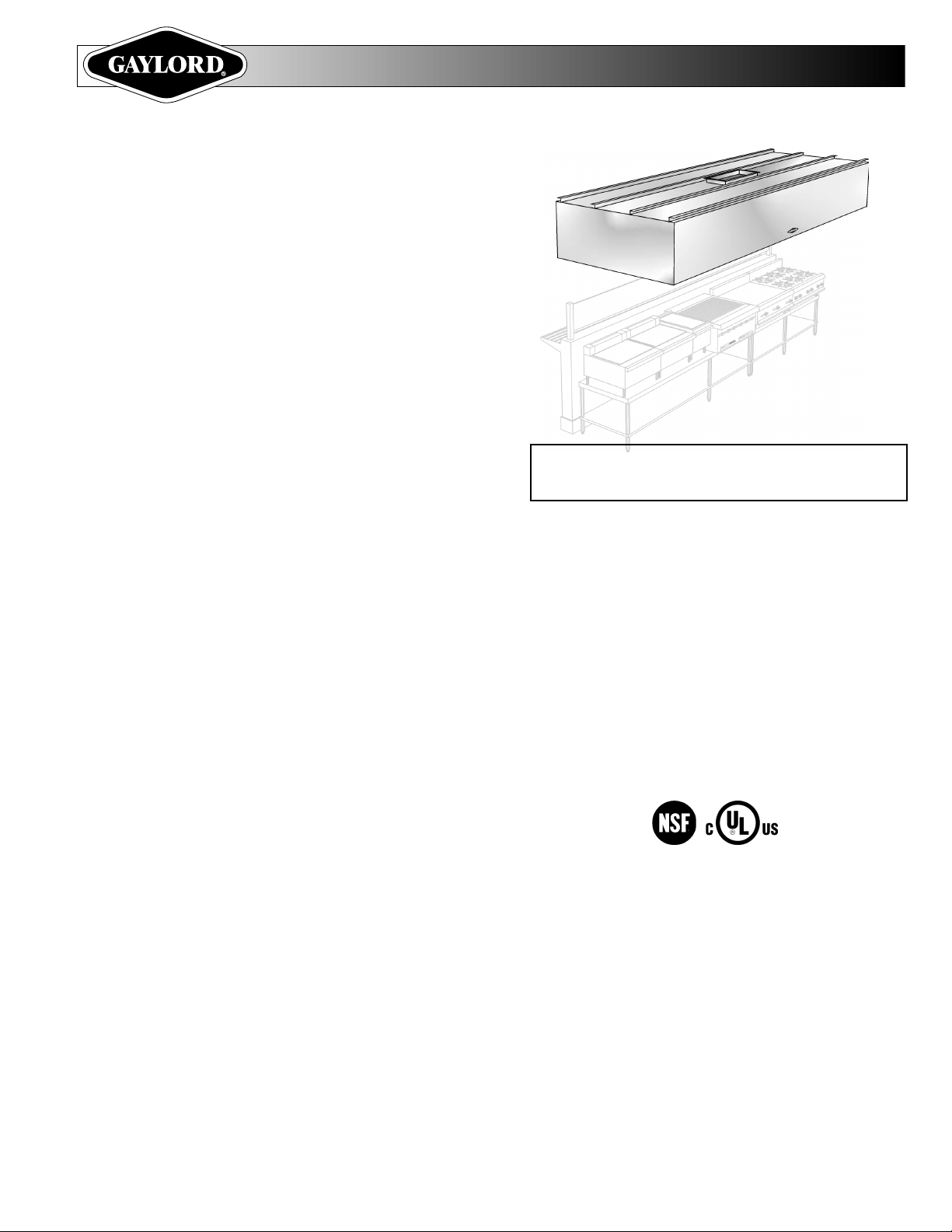
Ultima VentTM with UV Technology
MODEL “GX2-UV-BDL-DS-CL”
CARTRIDGE EXTRACTOR VENTILATOR WITH UV
GENERAL SPECIFICATIONS
Furnish Gaylord Ventilator Model “GX2-UV-___-BDL-DS-CL____________”
as shown on plans and in accordance with the following specifications:
GENERAL: Each ventilator shall have one high-velocity centrifugal
grease extractor with two air inlet slots, one on each side of the extractor.
One slot shall have an adjustable baffle to regulate the ration of exhaust
volume between the two slots. The extraction chamber shall contain one
or more removable “extractor inserts” with a grease extraction efficiency
of 90% of the mechanically extractable grease particulate. The extractor
insert shall include a built-in particulate separator creating one integral
extractor unit to remove for cleaning. Each extractor includes a Gaylord
Extractor Monitor ("GEM") to ensure that all cartridges are in place before
the UV lamps can operate. It shall also include ultraviolet lamps to remove
a majority of the remaining particulate for a total grease extraction
efficiency of up to 99% when operated and maintained in accordance with
the Gaylord Technical Manual and design specificiations. Extractor
inserts shall be constructed of stainless steel and contain full-length, selfdraining baffles. Extractors shall be easily removable, for periodic cleaning, from the floor area immediately in front of the equipment by utilizing an
extractor removal tool. The grease collecting gutter at the bottom of the
extractor housing shall slope to a drain at one end of the ventilator to a
removable stainless steel grease cup. The sloped gutter shall be
concealed by an apron which extends the full length of the hood. The
Ventilator shall include a "Super Capture"TM lip on the front panel for
enhancement of smoke and grease capture. Continuous brackets shall
be provided to facilitate hanging from the overhead building structure.
❏ (Optional) The ventilator shall include “Custom Air” baffles to reduce the
exhaust volume over specific cooking equipment as indicated on the plans
(add suffix “CA” to model number). The ventilator shall operate at air
quantities and static pressure as indicated on plans.
❏ Fuse Link Activated Fire Damper Option (series prefix “GX2-UVFDD”) The damper shall be activated by fuse link(s) located at the duct
collar. The ventilator shall be UL listed under the category “Exhaust Hood
with Exhaust Damper”.
❏ Ventilator without Fire Damper Option - (series prefix “GX2-UVND”) The ventilator shall be UL listed under the category “Exhaust Hood
without Exhaust Damper”.
ULTRAVIOLET LIGHT SECTION: The ventilator shall include ultraviolet
lamps mounted in modules located in the plenum section. There shall be
one or more UV modules, as dictated by the ventilator length, and each
module shall be on a slide track for easy removal. Access to the modules
shall be through keyed hinged doors, and shall include an interlock switch
to shut off the lamps in the event the doors are opened during operation.
A pressure switch shall be provided to monitor the airflow to prevent
operation of the lamps when the airflow is inadequate. A Gaylord Extractor
Monitor (“GEM”) shall be provided to shut off the lamps when a cartridge
is removed. Mounted on the face of the plenum of each ventilator section
shall be indicator lights to monitor “UV System On”, “UV Lamp Failure” and
“UV Safety Interlock Activated”. A duplicate set of these lights shall be
mounted on the ventilator control cabinet, Model CUV-100. The control
panel shall be equipped with an audible alarm indicating there is a lamp
failure or one of the safety interlock switches has been activated.
ITEM NO. _______________
APPLICATION
Used for cafeteria lines or single line island arrangement.
CONSTRUCTION: The ventilator shall be of all stainless steel
construction, not less than 18 gauge, type 300 series. All exposed
surfaces shall be a number 4 finish. The use of aluminized steel,
galvanized steel, or 430 stainless steel is not acceptable.
ELECTRICAL: The ventilator shall be factory pre-wired to single
connection points. On multiple section ventilators power for the UV
lamps must be supplied to each section. Wiring for controls and light
fixtures shall be furnished with coiled flex conduit for interconnecting
sections by applicable trades.
LIGHT FIXTURES: The ventilator shall be equipped with ❏ 100 watt
surface mounted incandescent, ❏ 150 watt recessed incandescent,
❏ recessed fluorescent, light fixtures. Light fixtures shall be factory
pre-wired to a single connection point. Ventilators built in multiple
sections shall be furnished with coiled flex conduit for interconnecting
sections.
ACCEPTANCE & APPROVALS: The ventilator shall be UL, CUL
and NSF listed. The ventilator shall comply with all requirements of
NFPA-96, IMC, UMC, BOCA and SBCCI model codes.
Patent Pending
GAYLORD INDUSTRIES
10900 SW AVERY ST. • TUALATIN, OREGON 97062 U.S.A.
PHONE: 800-547-9696 • FAX: 503-692-6048 • email: info@gaylordusa.com
www.gaylordusa.com
Ultima VentTM with UV Technology
ALL STAINLES STEEL
UV STATUS LIGHTS
AUDIBLE ALARM
CANCEL BUTTON
HOUR METER
MODEL “GX2-UV-___-BDL-DS-CL-____”
**
DAMPER OPTION
FDD = Fuse link damper at the duct collar
**
ND = No damper
DEPTH OF
VENTILATOR
For exact model designation add depth
following the letters “GX2-UV-ND-BDL-DS-CL”.
Example: “GX2-UV-ND-BDL-DS-CL-60”
34"
EXHAUST FAN/
SYSTEM ON/OFF
SWITCH
7" DEEP
8"
CUV-100
CONTROL CABINET
The manufacturer reserves the right to modify the materials and specifications resulting
from a continuing program of product improvement or the availability of new materials.
ITEM NO. _____________________ EST. WT. ________________________
LENGTH _____________ WIDTH ______________ HEIGHT ______________
LIGHTS ____________
qq
q
100W SURFACE INCANDESCENT
qq
qq
q
150W RECESSED INCANDESCENT
qq
q q
q
RECESSED FLUORESCENT
q q
ENGINEERING DATA
Mechanical Requirements
Exhaust volume depends upon the type of cooking equipment and the type and volume
of cooking. Refer to the Master Engineering Data Sheet in the Engineering Data section
of the Gaylord catalog for the charts to determine exhaust and supply volume, S.P.,
duct, hot water, and drain sizes. The standard “GX2-UV-BDL-DS-CL” ventilator
operates at 250 CFM/lin. ft. on the heavy side and 150 CFM/lin. ft. on the light side
for a total of 400 CFM/Lin. ft. If the cooking equipment requires more exhaust, as
determined by the Master Engineering Data Sheet, it may be necessary to use backto-back ventilator model “GX2-UV-BDL-BB” series (consult factory).
Electrical
o Provide 120 volt 20 amp, o 220/240 volt, 50-60 Hz., 24 hour service to
Gaylord CUV-100 Control Cabinet (refer to illustration above). To be fused
separately. Provide a separate 120 volt 20 amp service to each ventilator
section to power UV lamps. Ventilator lights to be on separate circuit, 120
volt standard, 220/240 volt optional.
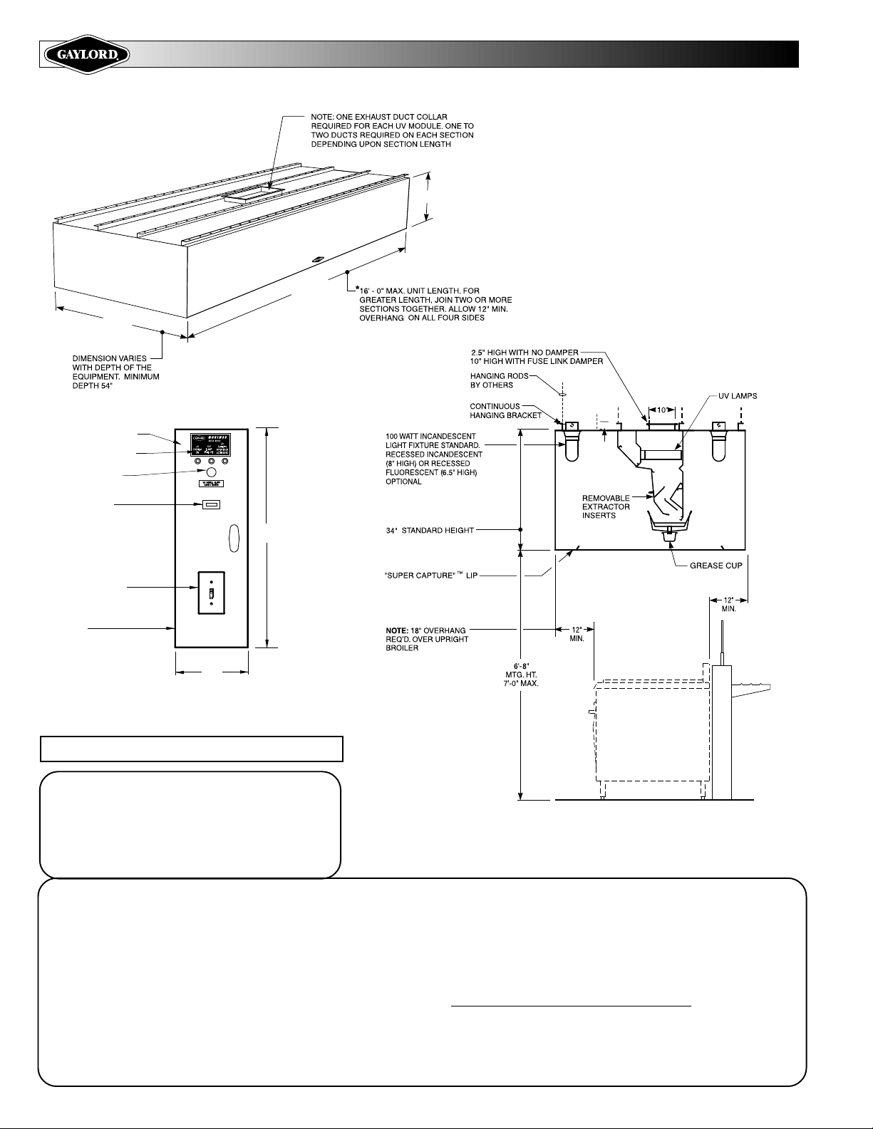
TYPICAL SECTION VIEW
Ventilator Lengths
Maximum unit length 16'-0" . For greater lengths, join two or more sections
together. Check to ensure that there is adequate access into building and kitchen
area.
Note: Ventilators manufactured outside North America; maximum unit length
*
10'-0".
Hanging Weight
Ventilator Width 4'-6" 5'-0" 5'-6"
Wt. / lineal ft. lbs. 120 125 130
Form No. GX2-UV-BDL-DS-CL 706-30817 © Copyright 2006, Gaylord Industries Litho USA
 Loading...