


EFFECTIVE DATE 5-14-03
THE
GAYLORD VENTILATOR
TECHNICAL MANUAL
FOR THE GRAND “GX2-FDD” SERIES
NON WATER-WASH VENTILATORS
GAYLORD INDUSTRIES
10900 S.W. AVERY STREET • P.O. BOX 1149 • TUALATIN, OREGON 97062-1149 U.S.A.
800-547-9696 • 503-691-2010 • FAX: 503-692-6048 • email: info@gaylordusa.com
“Undisputed World Leader in
Engineered Systems for
Commercial Kitchens”
tm
GAYLORD INDUSTRIES
World Headquarters: P.O . Bo x 1149 • T ualatin, Oregon 97062-1149 U .S .A.
To Our Customers. . .
Congratulations on your recent purchase of a Gaylord
kitchen exhaust hood system. W e are proud to be ab le
to provide you with a quality product that incorporates
the latest engineering concepts and is a result of over
50 years of experience in the foodservice kitchen
exhaust industry.
If you have other Gaylord equipment such as a Gaylord
Utility Distribution System, Quencher Fire Protection Sys-
tem, or Roof Top Air Handling Equipment, etc., please
refer to the corresponding supplementary equipment
manuals.
If you have further questions, please call us toll free at
1-800-547-9696 or email:info@gaylordusa.com. We are
more than happy to help.
Sincerely,
Gaylord Industries
PHONE: 503-691-2010 • 800-547-9696 • FAX: 503-692-6048 • email: gaylord@gaylordusa.com • www.gaylordusa.com
COMMERCIAL KITCHEN EXHAUST SYSTEMS • FIRE PROTECTION • UTILITY DISTRIBUTION • ROOF TOP UNITS • POLLUTION CONTROL
STREET ADDRESS: 10900 S.W. Avery Street, Tualatin, Oregon 97062-8549 U.S.A.
TABLE OF CONTENTS
“GX2-FDD” SERIES PRINCIPLE OF OPERATION ............................................... 3
STANDARD MODELS ............................................................................................ 6
MAINTENANCE AND CLEANING INSTRUCTIONS.............................................. 7
TROUBLESHOOTING ........................................................................................... 8
MEASURING INLET SLOT VELOCITY ................................................................. 10
WIRING DIAGRAM ................................................................................................ 13
PARTS LIST ........................................................................................................... 14
START-UP INSPECTION REPORT ....................................................................... 15
WARRANTY................................................................................. Inside back cover
PATENT NUMBERS
U.S.A.: 4,266,529
4,281,635
4,356,870
CANADA: 1,139,151
1,155,366
GERMANY: 8,034,240
ALL RIGHTS RESERVED. NO PART OF THIS BOOK MAY BE REPRODUCED, STORED
IN A RETRIEVAL SYSTEM, OR TRANSMITTED IN ANY FORM BY AN ELECTRIC, MECHANICAL, PHOTOCOPYING, RECORDING MEANS OR O THERWISE WITHOUT PRIOR
WRITTEN PERMISSION OF GAYLORD INDUSTRIES, INC. COPYRIGHT 2003.
© Copyright 2003, Gaylord Industries
The manufacturer reserves the right to modify the materials and
specifications resulting from a continuing program of product improvement or the availability of new materials.
ADDITIONAL COPIES $10.00
“GX2-FDD” SERIES PRINCIPLE OF OPERATION
The Gaylord “GX2-FDD” Series Non Water-Wash Ventilator
offers simplicity, economy and performance that no other
ventilator can offer. The unique “extractor insert” gives a
grease extraction efficiency far superior to that of a typical
baffle filter. The Gaylord “GX2-FDD” Series Ventilators are
UL Listed and meet all the requirements of NFPA #96 and the
International Mechanical Code.
EXHAUST FAN OPERATION
The exhaust fan is controlled by the Gaylord C-150 “Exhaust
Fan Start/Stop Switch”, an optional switch, or a standard wall
switch. The switch is usually located on a wall near the
ventilator. When the switch is flipped up to the on position,
the exhaust fan will come on.
GREASE EXTRACTION
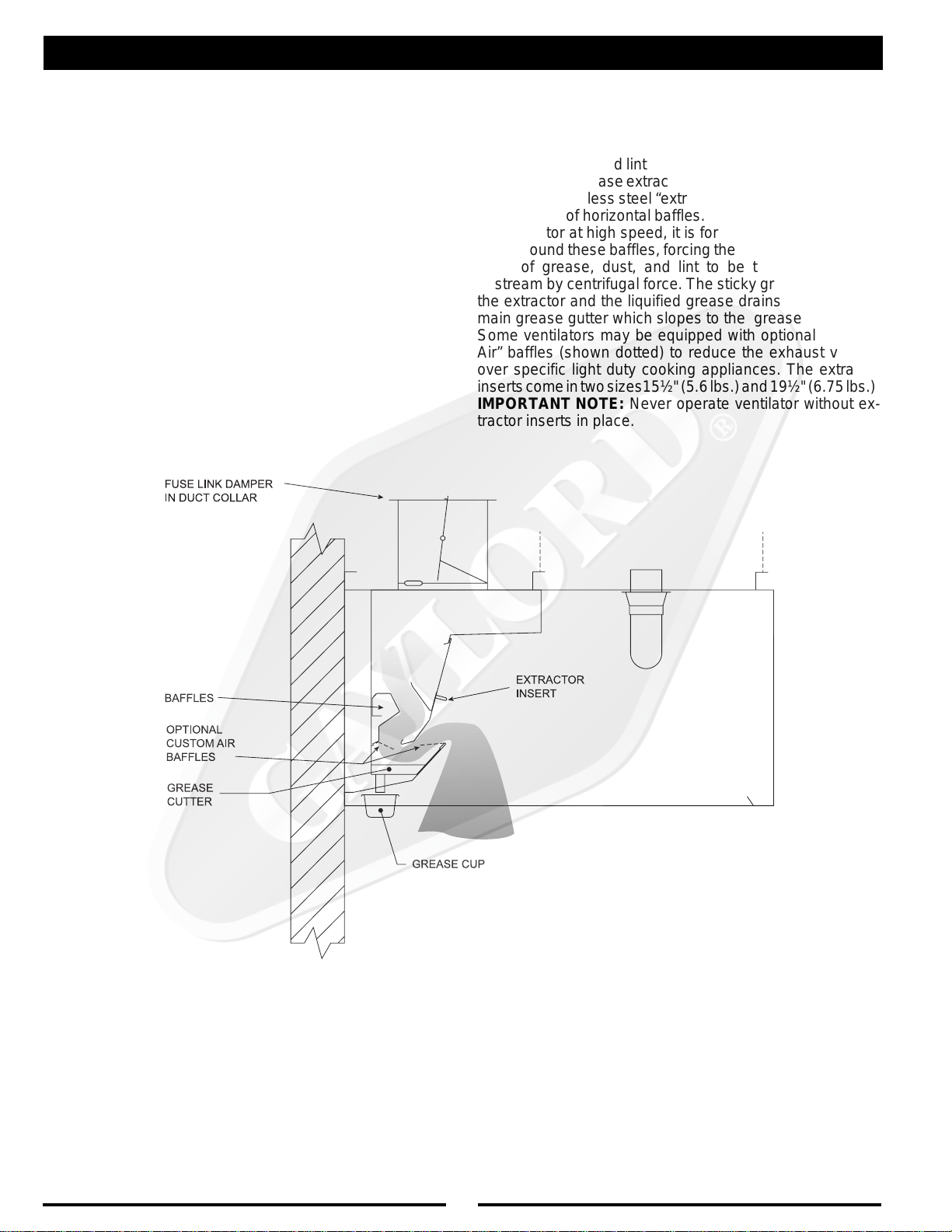
The Gaylord “GX2-FDD” Series Ventilator extracts 90% of
the grease, dust, and lint particles from the airstream passing through it. Grease extraction is accomplished by unique,
removable stainless steel “extractor inserts” which incorporate a series of horizontal baffles. As the air moves through
the extractor at high speed, it is forced to make a series of
turns around these baffles, forcing the heavier-than-air particles of grease, dust, and lint to be thrown out of the
airstream by centrifugal force. The sticky grease collects in
the extractor and the liquified grease drains down into the
main grease gutter which slopes to the grease cup. Note:
Some ventilators may be equipped with optional “Custom
Air” baffles (shown dotted) to reduce the exhaust volume
over specific light duty cooking appliances. The extractor
inserts come in two sizes15½" (5.6 lbs.) and 19½" (6.75 lbs.).
IMPORTANT NOTE: Never operate ventilator without ex-
tractor inserts in place.
GREASE EXTRACTION
FIG. 1
3
“GX2-FDD” SERIES PRINCIPLE OF OPERATION
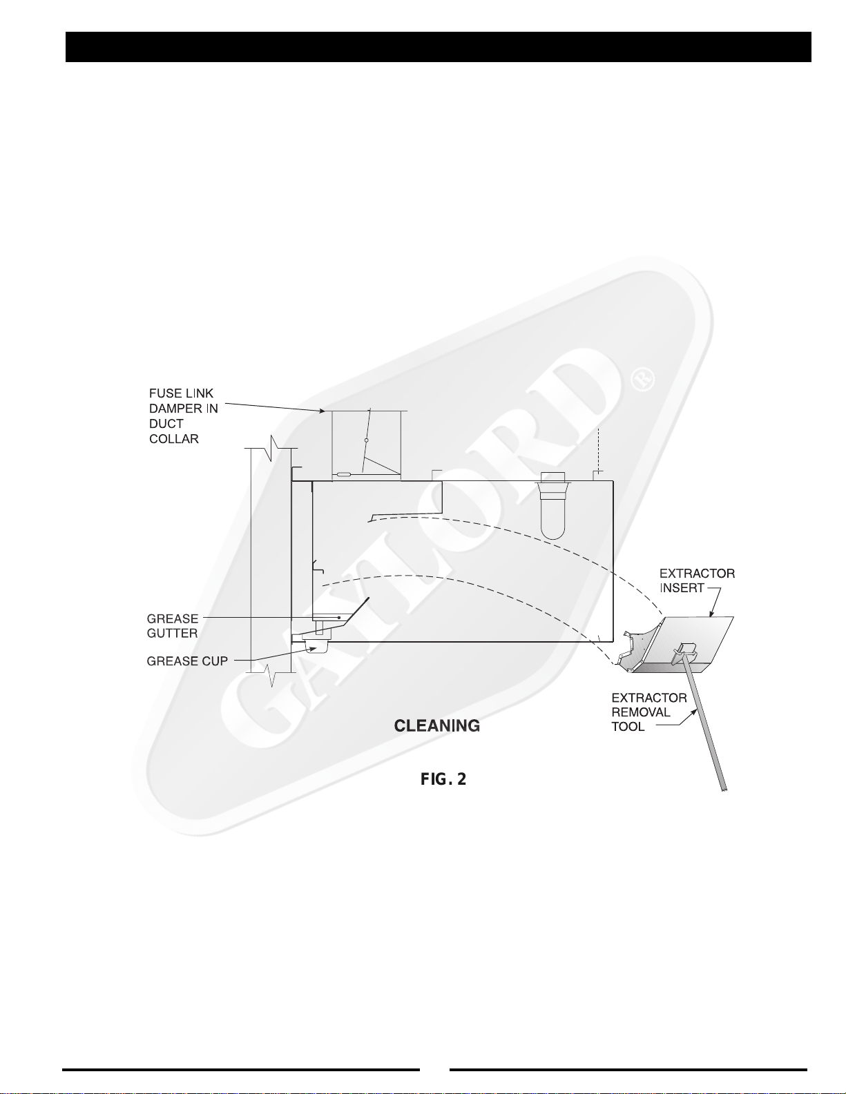
CLEANING
At the end of the cooking day the exhaust fan is turned off by
the “Exhaust Fan Start/ Stop Switch.” After the fan has been
turned off, the extractor inserts are removed and can be
washed either in a dishwasher or soaked and rinsed off. The
grease cup is also removed and emptied at this time. To ease
in the removal of the extractor inserts, an “Extractor Removal
Tool” is available which eliminates the need for kitchen
personnel to climb up on the cooking equipment, or up a
ladder.
FIG. 2
4
“GX2-FDD” SERIES PRINCIPLE OF OPERATION
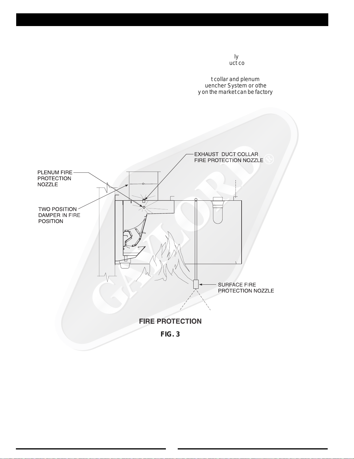
FIRE PROTECTION
NFPA #96 requires the use of surface, duct and plenum
protection on all hoods. It is these systems that are the first
line of defense against equipment fires.
The “GX2-FDD” Series ventilator incorporates a fuse link
damper at the duct collar. In the event of a fire, should the
fuse link at the duct collar reach 280°F, the fuse link melts
allowing the damper to close. (See Fig. 3) This prevents the
flames from entering the ductwork and spreading to other
parts of the building. The fire is contained in the kitchen area
where it can be properly fought. After the fire is extinguished
the fuse link in the duct collar needs to be replaced and the
damper reset.
Surface, duct collar and plenum fire protection utilizing The
Gaylord Quencher System or other fire protection systems
currently on the market can be factory installed as an option.
FIG. 3
5

STANDARD VENTILATOR MODELS
Model GX2-FDD-BDL
Application - Wall mounted canopy
style for all types of equipment.
Model GX2-FDD-BDL-DS
Application - For island style
cooking arrangements where one side
of the cooking line is light duty equipment
and the other side medium duty equipment.
ST ANDARD MAKE-UP AIR OPTIONS
The make-up air options shown below are available on all BDL Series Ventilators
except the MAI Series is not available on the GX2-FDD-BDL-CL.
Model GX2-FDD-BDL-CL
Application - For single island
arrangements
Model GX2-FDD-BDL-BB
Application - For island style
cooking arrangements over all duties
of equipment.
MODEL “MAW” SERIES
FRONT FACE DISCHARGE
This method of introducing make-up air into the
kitchen is flexible and has many advantages.
Make-up air is discharged through stainless steel
perforated panels as illustrated (MAW Series) or
optional registers (MAR Series). Typical supply
volume is 80% of the exhaust or more, depending on air balance desired. Supply air temperatures should range from 60 to 65°F (16 to 18°C),
but may be as low as 50°F (10°C) depending on
air volume, distribution, and internal heat load.
MODEL “MAI” SERIES
INTERNAL DISCHARGE
This method of introducing air into the hood is
typically referred to as the “short circuit” method.
This design has very limited applications and the
amount of supply air able to be introduced varies
considerably with the type of cooking equipment.
This air may be untempered air in most areas
depending upon climatic conditions and the type
of cooking equipment. The difference between
the quantity of air being introduced and the
amount of air being exhausted must be supplied
through a traditional make-up air system.
6

MAINTENANCE AND CLEANING INSTRUCTIONS
CLEANING
At the end of each cooking day, the exposed interior
surfaces of the ventilator should be wiped down and the
grease cup emptied. During the course of operation, grease
particles are gradually collecting inside the extractor inserts.
Daily , or at periodic intervals, depending on the type of cooking, the extractor inserts must be removed and cleaned.
To clean, proceed as follows:
1.Remove extractor inserts by hand or by using the
extractor removal tool. CAUTION: Care should be
taken when removing extractors, especially over fryers. It is recommended that the cooking equipment be
cooled down and the fryers be covered prior to removing
extractors. To remove, lift up slightly on e xtractor insert
and pull straight out.
2.Extractor inserts may be cleaned either by using a dish-
washer or by washing in a sink using hot water and a
degreasing detergent. Formula G-510 is highly
recommended for this application. For information
contact:
20/10 Products Inc.
P.O. Box 7609
Salem, OR 97303
Phone: 800-286-2010
Fax: 503-363-4296
E-mail: twentyten@juno.com
3.With the extractor inserts removed, wipe and clean the
back wall and the grease gutter with hot detergent wa-
ter. NOTE: If a steam or hot w ater pressure washer is
used for periodic cleaning of the interior, connect a hose
to the gutter drain and lead it to a floor sink or large
buck et to drain off the water.
4.T o replace the extractor inserts, care must be taken to
insure that point “A” rests in the rear clip as illustrated
in Fig. 4.
5.If the ventilator(s) has a fuse link operated supply duct
fire damper NFPA-96 requires inspection of the fuse
link every 6 months and replacement annually.
INSPECTION AND CLEANING REQUIREMENTS
The 2001 edition of NFP A-96 (Standard for V entilation Control and Fire Protection of Commercial Cooking Operations)
require that hoods, ducts and exhaust fans be inspected
by a properly trained, qualified and certified company or
person(s) in accordance with the following table.
Upon inspection, if found to be contaminated with deposits
from grease- laden vapors, the entire exhaust system shall
be cleaned by a properly trained, qualified, and certified
company or person(s) acceptable to the authority having
jurisdiction.
When a vent cleaning service is used, a certificate showing date of inspection or cleaning shall be maintained on
the premises. After cleaning is completed, the vent
cleaning contractor shall place or display within the kitchen
area a label indicating the date cleaned and the name of
the servicing company. It shall also indicate areas not
cleaned. Factory trained service agencies are certified by
Gaylord Industries, Inc. to perform these inspections. For
the name and phone number of your nearest agent call
800-547-9696 or www.ga ylordusa.com and go to service.
ELUDEHCSNOITCEPSNIMETSYSTSUAHXE
gnikooCfoemuloVroepyTycneuqerF
snoitarepognikoocleufdilosgnivressmetsySylhtnoM
snoitarepognikoocemulov-hgihgnivressmetsyS
gnikoockowrogniliorbrahc,gnikoocruoh-42sahcus
gnikoocemulov-etaredomgnivressmetsyS
snoitarepo
hcus,snoitarepognikoocemulov-wolgnivressmetsyS
ro,sessenisublanosaes,spmacyad,sehcruhcsa
sretnecroines
CAUTION: Care should be taken when removing extractors,
especially over fryers. It is recommended that the cooking
equipment be cooled down and the fryers be covered prior to
removing extractors.
ylretrauQ
yllaunnaimeS
yllaunnA
FIG. 4
7

.1tonsirotalitneV-ssoLekomS
TROUBLE-SHOOTING
MOTPMYSMELBORPELBISSOPNOITCAEVITCERROC
SSOLEKOMS
.ylreporpgnitsuahxe
.A
.gniwollofehtkcehcwolsiyticolev
yticolevriaegarevA-yticolevriawoL
.1
niebdluohstolsyrtneriaehthguorht
notrahCyticoleVriAehthtiwecnadrocca
.2
gnirusaemfodohtemreporproF.01egap
ehtfI.11egapotrefer,yticolevriaeht
.3
.naftsuahxeehtnotlebgnippilsronekorB
.leehwnaftsuahxeehtfonoitatorreporP
reviledtsumnaf(naftsuahxefoezisreporP
.)gnitaretalpeman
.4
.5
.B
.C
.D
.riapu-ekametauqedanI
nwostievahtsumrotalitneVdrolyaGehT
.1
hcus,tsuahxerehtoondnametsystsuahxe
.tiotnideitebdluohs,sdoohrehsawhsidsa
.sresuffidriapu-ekamdecalpylreporpmI
.1
.2
.3
.1
epytoneraIIfI.nideitsmetsysrotalitnev
.devomerebtsumyehtos
.rotalitnev
.aeranehctik
.ssolekomsnignitluser
.smetsystsuahxenehctik
.nepotfellenapnoitcepsnikrowtcuD
.noitisopreporpnironepotonrepmaD
erehttahtyfirevdnametsystcudtcepsnI
lliwrotalitnevehttadetceridriapu-ekaM
riaehtgnitpursidstfardssorcetaercylekil
srevuolehttsujdA.rotalitnevehtotniwolf
ehtmorfyawariapu-ekamehttceridot
hguorhtdereviledebdluohsriapu-ekaM
sretsigerrosresuffiddetarofrephtgnellluf
ehttuohguorhtdetubirtsidthgiehgniliecta
ehtraendetacolsretsigerriapu-ekaM
otdetsujdaebdluohssrevuoleht,rotalitnev
.rotalitnevehtmorfyawariaehttcerid
ehttariapu-ekamgnicrofrognitceriD
stfardssorcsetaercyllacipytrotalitnev
rofdeilppusebtsumriapu-ekaM
llahguorhtdetsuahxeriafotnemecalper
.E
NOITCARTXEESAERG
.1.noitcartxEesaerGrooP.ArotalitneVseireS"DDF-2XG"drolyaGehT
.2
.saeratnecajdamorf
.egrahcsidnaftsuahxE
.wolsiemulov
.1
.devomer
.2
.dednemmocer
.1debircsedsayticolevtolstelniehtkcehC
dnatsud,esaergehtfo%09otpustcartxe
gnissapmaertsriaehtmorfselcitraptnil
deniatniamdnadetareponehw,tihguorht
.snoitacificepsngisedhtiwecnadroccani
tonsirotalitnevehttahtsraeppatifI
tsuahxeehtyllacipyt,ylreporpgnitcartxe
ot%57tahtsi"bmuhtfoelur"larenegA
,hserfebdluohsriatnemecalperehtfo%08
thguorbria)deloocrodetaeh(,denoitidnoc
gniniamerehthtiw,aeranehctikehtotni
nehctikehtotniwolfotdewolla%52ot%02
ehtrevoneercsonebdluohserehT
ebdluohsti,dnuofsienofI.egrahcsid
ebtondluohsegrahcsidfonoitceridehT
drawnwodronsdniwgniliaverpehtotni
ylhgihsiegrahcsidlacitrevA.foorehtotno
siyticolevehtfI.21hguorht01segapno
roesaercni,egnarderiuqerehtnihtiwton
.deriuqersadeepsnafehtecuder
8

.1ehtnodenrutsihctiwsnafehtnehwfI
TROUBLE-SHOOTING
MOTPMYSMELBORPELBISSOPNOITCAEVITCERROC
NAFTSUAHXE
.noemoctonseodnaftsuahxe
.A
.B
.deppirt
Iepyt)citamotuA/nOsdnaH(AOHnaf
noitisopcitamotuaehtmorf
retratscitengamnorotcetorpdaolrevO
.1
.retnecdnammoc
.1
eht,desusihctiwsretratscitengam
devomneebevahyamhctiwsrotceles
.noitisopcitamotuaeht
ehtnonottub"teseR"ehthsuP
hsupehtdnaretratscitengam
ehtnonottub"naFtratS"eht
otrotcelesnrutdnahctiwskcehC
.C
.D
.deppirtrekaerbtiucricnaftsuahxE
.1
nahtiwdeppiuqesimetsysehtfI
.1
,naftsuahxeehtrofhctiwstcennocsid
.tuonwolbevahyamsesufroesufa
rekaerbtiucrictes-eR
dnasesuffoytiunitnockcehC
.yrassecenfiecalper
9

MEASURING INLET SLOT VELOCITY
MEASURING INLET SLOT VELOCITY
Smoke capture and grease extraction efficiency are de-
pendent upon the proper air velocity at the inlet slot of the
ventilator.The required average slot velocities are shown
on the “Air Velocity Chart” below. If the slot velocity is
below the required average, the exhaust fan must be
adjusted accordingly.
NOTE: The height of the inlet slot can vary depending
upon the design of the ventilator. It is, therefore, important
to first measure the inlet slot and compare it to the chart
below to determine the required average inlet slot velocity. The designed CFM per lineal foot is related to the
velocity as shown on the chart below. The total CFM for
the ventilator can be found on the ventilator nameplate.
(See Figure 6).
TRAHCYTICOLEVRIA
SEIRES"SD"TPECXESEIRES"2XG"LLAROF
motsuCtuohtiW
lanimoN
thgieH
fo
tolStelnI
dengiseD
repMFC
.tFlaeniL
selffaBriA
.niM mumitpO .xaM
telnIegarevA
)MPF(yticoleVtolS
dengiseD
repMFC
.tFlaeniL
motsuChtiW
selffaBriA
.niM mumitpO .xaM
telnIegarevA
)MPF(yticoleVtolS
"3
"4
052
072
582
003
004
0031
0631
5241
5641
0961
0541
051
0831
0051
5341
5751
0051
5261
5451
0781
0871
067
061
097
071
018
081
548
052
0401
088
008
078
038
009
558
539
088
0511
5901
*SROTALITNEVSEIRES"SD"ROF
rePMFCdengiseD
.tFlaeniL
latoT
tnorF
htoB
tolS
stolS
003
051
004
052
raeR
tolS
051
051
.niM mumitpO .xaM
067
5731
tolStnorF
088
008
0251
0541
telnIegarevAderiuqeR
)MPF(yticoleVtolS
tolSraeR
.niM mumitpO .xaM
595
526
595
526
556
556
Air velocity readings less than what is specified on the “Air
Velocity Chart” may allow smoke and grease to escape
the confines of the ventilator and/or reduce grease extraction efficiency. This can result in grease deposits which
lead to sanitation problems or fire hazards if left uncorrected. If air velocity readings are higher than those
specified, it will require more energy to operate the
exhaust fan and excessive noise levels will result. Higher
or lower velocities than the required average will normally
put the entire heating and ventilating system out of balance. When measuring the air velocity it is very important
to take an average reading across the inlet slot plane as
described on Page 11. Positioning the sensing head
incorrectly will give velocity readings that cannot be compared to the “Air Velocity Chart”.
10

FIG. 5A
FIG. 5B
MEASURING INLET SLOT VELOCITY
The standard instrument used for measuring the inlet velocities on a Gaylord
Ventilator is a Pacer, Model DA40 or DA4000 Digital Anemometer. This
instrument is the easiest, most accurate and the best suited for measuring
ventilator inlet slot velocities. To take accurate air velocity readings, follow
the instructions below.
Instructions
1. It is first necessary to determine if the ventilator includes Custom Air baffles
as shown in Fig. 5B. If shop drawings are available, and if equipped, the
custom baffles and their location will be noted on the front elevation. If not
available, to determine if Custom Air baffles are provided run your hand along
the bottom inlet slot and feel for the Custom Air baffle as illustrated in Fig. 5B.
2. If the ventilator includes Custom Air baffles, it will be necessary to take two
sets of readings - one for the section of ventilator that includes Custom Air baffles
and one where it does not.
3. Attached the sensing head guide bracket, Gaylord Part Number 18408, to
the sensing head.
4. Attach the cable from the sensing head to the meter and the handle
sections to the sensing head.
5. Place the sensing head guide bracket against the lower lip of the inlet slot
as illustrated.
6. Using the 16 second averaging feature on the meter, slide the sensing head along
the slot, back and forth, for a 3'-0" to 4'-0" distance, and record the velocity at the end
of the 16 second mark. Continue this process for the full length of the ventilator.
Important Note: If the ventilator includes custom air baffles as illustrated in Fig.
5B, always take separate readings on the section of the ventilator that includes
custom air from the section that does not have the baffles. Non custom air and
custom air readings must be recorded separately. Do not average them together.
Important Note: On the rear slot of a Model BDL-DS Series, do not use the
guide bracket. Refer to Figure 5C.
7. Record the velocity (fpm) on the start up inspection report form. A sample
report form, which can be photocopied, is provided on page 16.
8. The designed, or optimum velocity, is noted on the shop drawings and
the Air Velocity Chart on page 10. Two velocities will be noted if the ventilator
includes custom air baffles.
9. Compare the recorded air velocity to the designed air velocity shown on the
shop drawings or the Air Velocity Chart on page 10. The recorded velocity may
be slightly lower or higher providing that it is within the minimum and maximum
range as shown on the Air Velocity Chart .
If the air velocity is outside the minimum/maximum range, the performance of
the ventilator will be affected and therefore the exhaust fan must be adjusted.
FIG. 5C
CROSS SECTION OF TYPICAL
VENTILATOR INLET SLOTS
11

LISTED
370Y
EXHAUST HOOD WITH
EXHAUST DAMPER
THIS EXHAUST HOOD HAS BEEN TESTED
TO STANDARD UL 710 "EXHAUST HOODS
FOR COMMERCIAL COOKING
EQUIPMENT"
THIS EXHAUST HOOD IS LISTED UNDER UL
FILE NUMBER 11403
THIS EXHAUST HOOD MEETS ALL REQUIRE-
MENTS OF THE LATEST EDITION OF NFPA-
96 AND THE IMC (INTERNATIONAL MECHANI-
CAL CODE)
o
SUPPLIED WITH FACTORY INSTALLED UL LISTED
GRINNELL CORP. EA-1, 1/4" ORIFICE, 65 DEGREE
DEFLECTOR SPRINKLER(S) FOR THE PROTEC-
TION OF UNLIMITED LENGTH OF GREASE DUCT
HAVING A MAXIMUM DUCT PERIMETER OF 50
INCHES PER SPRINKLER. CONNECT TO NFPA 13
SPRINKLER SYSTEM WATER SUPPLY ONLY.
PATENT PENDING
MEASURING INLET SLOT VELOCITY
ENGINEERING DATA
1. MINIMUM TOTAL EXHAUST
VOLUME FOR THIS HOOD SECTION
2. MAXIMUM TOTAL SUPPLY
VOLUME FOR THIS HOOD SECTION
3. EXHAUST STATIC PRESSURE AT
DUCT COLLAR
4. SUPPLY STATIC PRESSURE AT
DUCT COLLAR
5. THIS HOOD SECTION SUITABLE FOR APPLIANCES WITH MAXIMUM COOKING
SURFACE TEMPERATURE OF:
˚F FOR LINEAL FT. OF HOOD
˚F FOR LINEAL FT. OF HOOD
6. REFER TO GAYLORD VENTILATOR TECHNICAL MANUAL FOR INLET
VELOCITY REQUIREMENTS AND METHOD OF CHECKING VELOCITY
7. ELECTRICAL RATING OF LIGHT FIXTURES: 120 VOLT, 60 HZ. OR 220 VOLT,
50 HZ. OVERALL RATING - 12 AMPS OR LESS
8. ON "GX2" and "PG" SERIES VENTILATORS EQUIPPED WITH FUSE LINK
OPERATED EXHAUST FIRE DAMPER USE ONLY 280˚ F , RATED 30 LBS. MIN. UL
LISTED FUSIBLE LINK FOR REPLACEMENT
9
. IF HOOD IS EQUIPPED WITH INTEGRAL MAKE-UP AIR WITH FUSE LINK OPER-
ATED FIRE DAMPER USE ONLY 165˚ F, RATED 30 LBS. MIN. UL LISTED FUSIBLE
LINKS FOR REPLACEMENT
10.DUCTWORK AND EXHAUST FAN
A. STATIC PRESSURE OF DUCT SYSTEM MUST BE ADDED TO VENTILATOR
STATIC FOR TOTAL SYSTEM STATIC
B. ALL DUCTWORK MUST BE WELDED LIQUIDTIGHT
HOOD MOUNTING REQUIREMENTS
MINIMUM DISTANCE FROM COOKING SURFACE TO FRONT
LOWER EDGE OF HOOD
MAXIMUM DISTANCE FROM COOKING SURFACE TO FRONT
LOWER EDGE OF HOOD
MINIMUM OVERHANG FROM FRONT OF HOOD CAVITY TO
FRONT OF COOKING SURFACE
MAXIMUM SETBACK FROM FRONT OF HOOD CAVITY TO
FRONT OF COOKING SURFACE
MINIMUM OVERHANG FROM SIDE OF HOOD TO EDGE OF
COOKING SURFACE
SERIAL NO:
MODEL NO:
C.F.M.
C.F.M.
W.G.
W.G.
TOTAL EXHAUST CFM HERE
TOTAL SUPPLY CFM HERE
FIGURE 6
The total required exhaust volume can be
found stamped on the UL nameplate located
on each hood section.
WORLD HEADQUARTERS
GAYLORD INDUSTRIES, INC.
10900 S.W. AVERY STREET
TUALATIN, OR 97062-8549 USA
PHONE: 1-503-691-2010
FAX: 1-503-692-6048
EMAIL: info@gaylordusa.com
UL-GX2/PG 1000
MAINTENANCE INSTRUCTIONS
1. REMOVE, INSPECT AND CLEAN FILTERS OR GAYLORD EXTRACTOR
CARTRIDGES AS REQUIRED
2. REMOVE AND EMPTY GREASE CUP AS REQUIRED
3. CAUTION - DO NOT OPERATE VENTILATOR WITHOUT FILTERS OR EXTRACTOR
CARTRIDGES IN PLACE
4. REPLACE FILTERS IN "PG" SERIES ONLY WITH UL CLASSIFIED GREASE FILTERS.
IN "PGX" AND "GX2" SERIES REPLACE WITH GAYLORD INDUSTRIES
EXTRACTOR CARTRIDGES.
5. IF THE VENTILATOR(S) HAS A FUSE LINK OPERATED EXHAUST OR SUPPLY
DUCT FIRE DAMPER THE NATIONAL FIRE PROTECTION ASSOCIATION'S
PAMPHLET NFPA-96 REQUIRES INSPECTION OF THE FUSE LINK EVERY 6
MONTHS AND REPLACED ANNUALLY. REFER TO THE GAYLORD VENTILATOR
TECHNICAL MANUAL FOR DETAILS.
12

WIRING DIAGRAM
13

PARTS LIST
DROLYAG
.ONTRAP
08381
58381
54781
64781
12301
32301
00481
91101raelC-ebolGthgiL
NOITPIRCSEDNOITARTSULLI
tresnIrotcartxE"2/1-51
tresnIrotcartxE"2/1-91
)srotcartxE.tF.niL/MFC052(
tresnIrotcartxE"2/1-51
tresnIrotcartxE"2/1-91
)srotcartxE.tF.niL/MFC004(
stcuDylppuSrofkniLesuFF°561
stcuDtsuahxErofkniLesuFF°082
looTlavomeRrotcartxE
)srotcartxE.tF.niL/MFC004+052roF(
11231
01231
11101
21101
57031"4x"6x"4/1-3puCesaerG
41381lortnoChctiwSpotS/tratS051-C
emarF&sneLthgiLtnecsednacnI
reniateR&sneLthgiLdesseceR"21x"21
emarF&sneLthgiLtnecseroulF
reniateR&sneLthgiLdesseceR.tF2
reniateR&sneLthgiLdesseceR.tF3
reniateR&sneLthgiLdesseceR.tF4
14

VENTILATOR START-UP INSPECTION REPORT
For Model “GX2-FDD” Series Ventilators
Job Name ______________________________________________________________________________ Gaylord Representative___________________________________________________________
Address ________________________________________________________________________________ Representative Company Name ____________________________________________________
______________________________________________________________________________________ File Number_____________________________________ Date__________________________
City/State Zip
MAKE-UP AIR
1. Kitchen make-up air supply is turned on______Yes______No
2. Type of make-up air
¨ Ceiling Registers ¨ Built into Hood
¨ Ceiling Linear Diffusers ¨ Other
3. If ceiling register or linear diffusers approximate distance from face of hood
_____________________________________________________________
FIRE DAMPER INFORMATION
¨ V entilator has electric fire damper (GX2 Series)
¨ V entilator has fuse link fire damper (GX2-FDD Series)
¨ V entilator does not ha v e a fire damper (GX2-ND Series)
AIR VOLUME READINGS
Push “Start Fan” and take velocities. Record as follows: Exhaust record in the “EX” row, Exhaust at Custom
Air baffles (if applicable) record in the “CA” row, and Make-up Air record in the “MA” ro w.
.ONMETI.ONLAIRESDOOH
XE
AC
AM
XE
AC
AM
XE
AC
AM
THGIROTTFELMORF)MPF(SEITICOLEVRIA
EGRAHCSIDRIAPU-EKAMROTOLSDOOH
EGAREVA
ELECTRIC DAMPER TEST (If equipped):
1. Remove one or more extractors so damper is visible. Push the “START FAN” button.
A. The damper should move to the fully opened position in approx. 1 minute 15 seconds. _____Yes ___No
B. The exhaust fan came on ___Yes ___No
2. Push “STOP FAN” button.
A. The damper should move to the fully closed position in approx. 15 seconds_____Yes_____No
B. The exhaust fan shut off ___Yes ___No
3. If the “GX2” Series ventilator(s) is interconnected with any “CG3” water wash series, perform the following
test:
A. With the exhaust fan on, open the electrical compartment on the control cabinet and push the “FIRE
TEST” button. The following should occur:
1. Exhaust fan shut off ___Yes ___No
2. Damper fully closed ___Yes ___No
B. At conclusion of the test push the “CANCEL” button. The following should occur:
1. The damper stayed closed ___Yes ___No
2. Fan stay ed off ___Yes ___No
C. Push the “START FAN” button. The following should occur:
1. Damper moves to the fully open position ___Yes ___No
2. Exhaust fan comes on ___Yes ___No
INST ALLA TIONINCLUDES THE FOLLOWING:
¨ Gaylord Rooftop Unit (GRT)
¨ Gaylord Clearair Pollution Control Unit (RSPC) ¨ The Gaylord “Quencher” Fire Protection System
¨ Gaylord Distributor (UDS) ¨ Wet Chemical Fire Protection System
Personnel provided with ventilator technical man ual________Yes________No
Inspection Witnessed By (Print Name) ______________________________________________________
Signature ________________________________________________ Date _______________________
Comments____________________________________________________________________________
____________________________________________________________________________________
____________________________________________________________________________________
____________________________________________________________________________________
____________________________________________________________________________________
__________________________________________________________________________________________________
__________________________________________________________________________________________________
Distribution: WHITE-Gaylord Industries, Inc. YELLOW-Customer PINK-Dealer GOLDENROD-Sales Rep Litho U.S.A.
GAYLORD INDUSTRIES P.O. BOX 1149 •10900 S. W . A very Street • Tualatin, OR 97062-1149
PHONE:1-503-691-2010 • FAX: 1-503-692-6048 •
email:info@gaylordusa.com
Form No. GX2SUR200

LIMITED WARRANTY
THE GAYLORD NON WATER-WASH VENTILATOR
LIMITED WARRANTY
August 2000
The Gaylord Ventilator and component parts furnished with The Gaylord Ventilator by the
Licensed Gaylord Manufacturer are warrantied by the Licensed Gaylord Manufacturer
producing the ventilator to be free from defects of material and workmanship under normal
use when installed, operated and serviced in accordance with factory recommendations.
The Licensed Gaylord Manufacturer's obligation under this warranty and any warranties
implied by law shall be limited to repairing or replacing at its option any part of said
equipment when the Licensed Gaylord Manufacturer's examination shall disclose to its
satisfaction to be thus defective, for a period of one (1) year from the date of beneficial use,
or eighteen months from date of shipment, whichever occurs first, provided proper and
acceptable evidence of such is recorded at the f actory . THE LICENSED GA YLORD MANU-
F ACTURER SHALL NOT BE RESPONSIBLE FOR INCIDENTAL OR CONSEQUENTIAL
DAMAGES RESULTING FROM A BREACH OF THIS WARRANTY.
In the United States the labor required to make repairs and replacements under this war-
ranty shall be furnished by Gaylord Industries Inc. or the Licensed Gaylord Manufacturer or
its authorized representative. Such labor shall only be provided Mondays through Fridays
between the hours of 8 a.m. and 4 p.m. Requests for repairs or replacement parts should
be made to GA YLORD INDUSTRIES, P.O. Bo x 1149, Tualatin, Oregon 97062-1149.
Outside the United States, all replacement parts furnished under this warranty shall be
F . O.B. Gaylord Industries, Tualatin, Oregon U.S.A. The owner shall pa y the necessary freight
delivery charges, and the necessary labor for removal and installation of parts, and any
tariffs, duties or taxes.
This warranty does not cover routine maintenance or malfunctions or improper operation
caused by fluctuating electrical power or power surges, and improper exhaust fan operation.
This is the sole warranty with respect to the aforesaid items. NEITHER THE GAYLORD
LICENSEE NOR ANY OTHER PARTY MAKES ANY OTHER WARRANTY OF ANY KIND
WHATSOEVER, EXPRESSED OR IMPLIED, AND ALL IMPLIED WARRANTIES OF
MERCHANTABILITY AND FITNESS FOR A PARTICULAR PURPOSE WHICH EXCEED
THE AFORESAID OBLIGA TIONS ARE HEREBY DISCLAIMED AND EXCLUDED FR OM
THIS AGREEMENT.

WORLDWIDE SALES, MANUFACTURING AND SERVICE
FOR THE NAME AND LOCATION OF THE NEAREST
CERTIFIED SERVICE AGENCY, VISIT OUR WEB SITE:
WWW.GAYLORDUSA.COM
OR CONTACT US AT:
GAYLORD INDUSTRIES
P.O. BOX 1149 • 10900 S.W. AVERY STREET
TUALATIN, OREGON 97062-1149 U.S.A
Phone: 503-691-2010
1-800-547-9696
Fax: 503-692-6048
email: info@gaylordusa.com
LOCAL SERVICE AGENCY
FORM NO. TM-GX2-FDD-501/30649 © COPYRIGHT 2003, GAYLORD INDUSTRIES LITHO IN U.S.A.
 Loading...