

Gateway NV42 Series Service Manual

Gateway NV42 Series
Service Guide
PRINTED IN TAIWAN
Service guide files and updates are available
on the ACER/CSD web; for more information,
please refer to http://csd.acer.com.tw

II
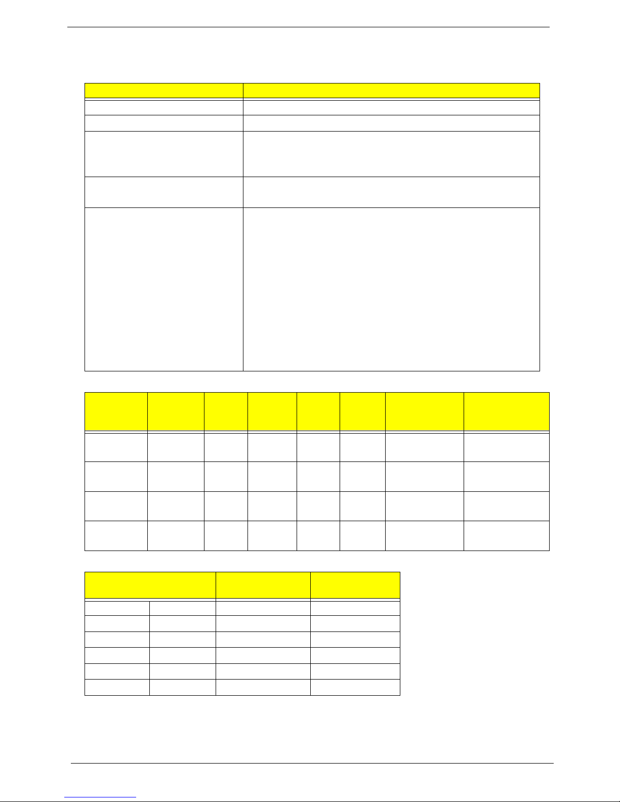
Revision History
Please refer to the table below for the updates made on this service guide.
Date Chapter Updates

III
Copyright
Copyright © 2009 by Acer Incorporated. All rights reserved. No part of this publication may be reproduced,
transmitted, transcribed, stored in a retrieval system, or translated into any language or computer language, in
any form or by any means, electronic, mechanical, magnetic, optical, chemical, manual or otherwise, without
the prior written permission of Acer Incorporated.
Disclaimer
The information in this guide is subject to change without notice.
Acer Incorporated makes no representations or warranties, either expressed or implied, with respect to the
contents hereof and specifically disclaims any warranties of merchantability or fitness for any particular
purpose. Any Acer Incorporated software described in this manual is sold or licensed "as is". Should the
programs prove defective following their purchase, the buyer (and not Acer Incorporated, its distributor, or its
dealer) assumes the entire cost of all necessary servicing, repair, and any incidental or consequential
damages resulting from any defect in the software.
Acer is a registered trademark of Acer Corporation.
Intel is a registered trademark of Intel Corporation.
Pentium and Pentium II/III are trademarks of Intel Corporation.
Other brand and product names are trademarks and/or registered trademarks of their respective holders.
IV
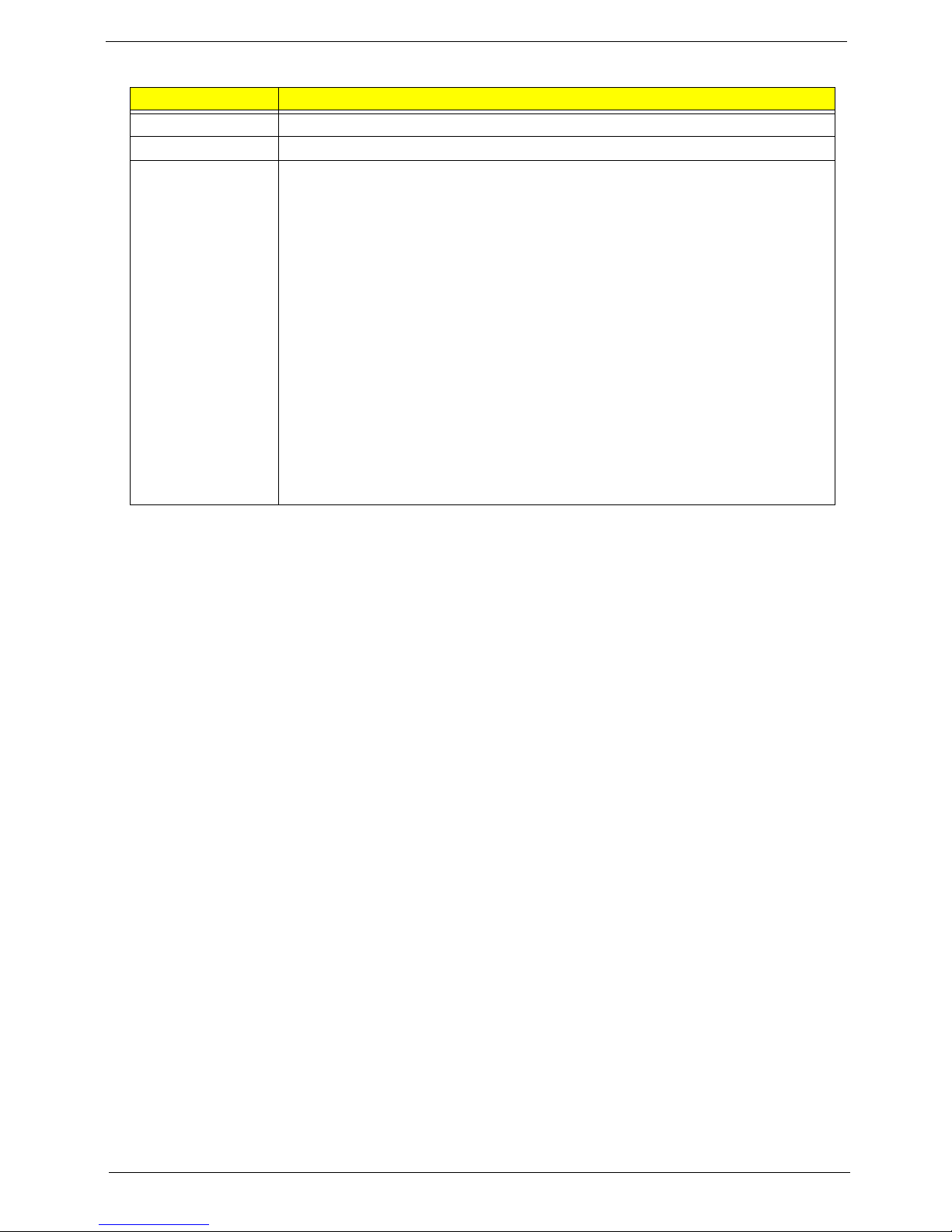
Conventions
The following conventions are used in this manual:
SCREEN MESSAGES Denotes actual messages that
appear on screen.
NOTE Gives bits and pieces of additional
information related to the current
topic.
WARNING Alerts you to any damage that might
result from doing or not doing
specific actions.
CAUTION Gives precautionary measures to
avoid possible hardware or software
problems.
IMPORTANT Reminds you to do specific actions
relevant to the accomplishment of
procedures.

V
Preface
Before using this information and the product it supports, please read the following general information.
1. This Service Guide provides you with all technical information relating to the BASIC CONFIGURATION
decided for Acer's "global" product offering. To better fit local market requirements and enhance product
competitiveness, your regional office MAY have decided to extend the functionality of a machine (e.g.
add-on card, modem, or extra memory capability). These LOCALIZED FEATURES will NOT be covered
in this generic service guide. In such cases, please contact your regional offices or the responsible
personnel/channel to provide you with further technical details.
2. Please note WHEN ORDERING FRU PARTS, that you should check the most up-to-date information
available on your regional web or channel. If, for whatever reason, a part number change is made, it will
not be noted in the printed Service Guide. For ACER-AUTHORIZED SERVICE PROVIDERS, your Acer
office may have a DIFFERENT part number code to those given in the FRU list of this printed Service
Guide. You MUST use the list provided by your regional Acer office to order FRU parts for repair and
service of customer machines.

VI

VII
Table of Contents
System Specifications 1
Features . . . . . . . . . . . . . . . . . . . . . . . . . . . . . . . . . . . . . . . . . . . . . . . . . . . . . . . . . . . .1
System Block Diagram . . . . . . . . . . . . . . . . . . . . . . . . . . . . . . . . . . . . . . . . . . . . . . . . .4
Gateway Notebook tour . . . . . . . . . . . . . . . . . . . . . . . . . . . . . . . . . . . . . . . . . . . . . . . .5
Front View . . . . . . . . . . . . . . . . . . . . . . . . . . . . . . . . . . . . . . . . . . . . . . . . . . . . . . .5
Left View . . . . . . . . . . . . . . . . . . . . . . . . . . . . . . . . . . . . . . . . . . . . . . . . . . . . . . . .6
Right View . . . . . . . . . . . . . . . . . . . . . . . . . . . . . . . . . . . . . . . . . . . . . . . . . . . . . . .7
Rear View . . . . . . . . . . . . . . . . . . . . . . . . . . . . . . . . . . . . . . . . . . . . . . . . . . . . . . .7
Bottom View . . . . . . . . . . . . . . . . . . . . . . . . . . . . . . . . . . . . . . . . . . . . . . . . . . . . .8
Keyboard Area (selected models) . . . . . . . . . . . . . . . . . . . . . . . . . . . . . . . . . . . . .9
LCD Panel . . . . . . . . . . . . . . . . . . . . . . . . . . . . . . . . . . . . . . . . . . . . . . . . . . . . . .10
Status Indicators . . . . . . . . . . . . . . . . . . . . . . . . . . . . . . . . . . . . . . . . . . . . . . . . .11
TouchPad Basics . . . . . . . . . . . . . . . . . . . . . . . . . . . . . . . . . . . . . . . . . . . . . . . .12
Using the Keyboard . . . . . . . . . . . . . . . . . . . . . . . . . . . . . . . . . . . . . . . . . . . . . . . . . .13
Key Types . . . . . . . . . . . . . . . . . . . . . . . . . . . . . . . . . . . . . . . . . . . . . . . . . . . . . .13
Windows Keys . . . . . . . . . . . . . . . . . . . . . . . . . . . . . . . . . . . . . . . . . . . . . . . . . .14
System Keys . . . . . . . . . . . . . . . . . . . . . . . . . . . . . . . . . . . . . . . . . . . . . . . . . . . .15
Hardware Specifications and Configurations . . . . . . . . . . . . . . . . . . . . . . . . . . . . . . .16
System Utilities 25
BIOS Setup Utility . . . . . . . . . . . . . . . . . . . . . . . . . . . . . . . . . . . . . . . . . . . . . . . . . . . .25
Navigating the BIOS Utility . . . . . . . . . . . . . . . . . . . . . . . . . . . . . . . . . . . . . . . . .25
Gateway NV42 AMD BIOS . . . . . . . . . . . . . . . . . . . . . . . . . . . . . . . . . . . . . . . . . . . . .26
Information . . . . . . . . . . . . . . . . . . . . . . . . . . . . . . . . . . . . . . . . . . . . . . . . . . . . .26
Main . . . . . . . . . . . . . . . . . . . . . . . . . . . . . . . . . . . . . . . . . . . . . . . . . . . . . . . . . .28
Advanced . . . . . . . . . . . . . . . . . . . . . . . . . . . . . . . . . . . . . . . . . . . . . . . . . . . . . .29
Security . . . . . . . . . . . . . . . . . . . . . . . . . . . . . . . . . . . . . . . . . . . . . . . . . . . . . . . .30
Boot . . . . . . . . . . . . . . . . . . . . . . . . . . . . . . . . . . . . . . . . . . . . . . . . . . . . . . . . . . .33
Exit . . . . . . . . . . . . . . . . . . . . . . . . . . . . . . . . . . . . . . . . . . . . . . . . . . . . . . . . . . .34
BIOS Flash Utility . . . . . . . . . . . . . . . . . . . . . . . . . . . . . . . . . . . . . . . . . . . . . . . . . . . .35
Using the Flash16 Utility to Update the BIOS . . . . . . . . . . . . . . . . . . . . . . . . . . .35
WinFlash Utility . . . . . . . . . . . . . . . . . . . . . . . . . . . . . . . . . . . . . . . . . . . . . . . . . .35
Remove HDD/BIOS Password Utilities . . . . . . . . . . . . . . . . . . . . . . . . . . . . . . . . . . . .36
Machine Disassembly and Replacement 43
Disassembly Requirements . . . . . . . . . . . . . . . . . . . . . . . . . . . . . . . . . . . . . . . . . . . .43
Related Information . . . . . . . . . . . . . . . . . . . . . . . . . . . . . . . . . . . . . . . . . . . . . . .43
General Information . . . . . . . . . . . . . . . . . . . . . . . . . . . . . . . . . . . . . . . . . . . . . . . . . .44
Pre-disassembly Instructions . . . . . . . . . . . . . . . . . . . . . . . . . . . . . . . . . . . . . . .44
Disassembly Process . . . . . . . . . . . . . . . . . . . . . . . . . . . . . . . . . . . . . . . . . . . . .44
External Module Disassembly Process . . . . . . . . . . . . . . . . . . . . . . . . . . . . . . . . . . .45
External Modules Disassembly Flowchart . . . . . . . . . . . . . . . . . . . . . . . . . . . . .45
Removing the Battery Pack . . . . . . . . . . . . . . . . . . . . . . . . . . . . . . . . . . . . . . . .46
Removing the Lower Covers . . . . . . . . . . . . . . . . . . . . . . . . . . . . . . . . . . . . . . . .47
Removing the ODD Module . . . . . . . . . . . . . . . . . . . . . . . . . . . . . . . . . . . . . . . .48
Removing the DIMM Modules . . . . . . . . . . . . . . . . . . . . . . . . . . . . . . . . . . . . . . .50
Removing the WLAN Module . . . . . . . . . . . . . . . . . . . . . . . . . . . . . . . . . . . . . . .51
Removing the HDD Module . . . . . . . . . . . . . . . . . . . . . . . . . . . . . . . . . . . . . . . .53
Main Unit Disassembly Process . . . . . . . . . . . . . . . . . . . . . . . . . . . . . . . . . . . . . . . . .55
Main Unit Disassembly Flowchart . . . . . . . . . . . . . . . . . . . . . . . . . . . . . . . . . . . .55
Removing the Switch Cover . . . . . . . . . . . . . . . . . . . . . . . . . . . . . . . . . . . . . . . .56
Removing the Keyboard . . . . . . . . . . . . . . . . . . . . . . . . . . . . . . . . . . . . . . . . . . .58
Removing the LCD Module . . . . . . . . . . . . . . . . . . . . . . . . . . . . . . . . . . . . . . . . .60
Removing the Upper Cover . . . . . . . . . . . . . . . . . . . . . . . . . . . . . . . . . . . . . . . .64

VIII
Table of Contents
Removing the Speaker Modules . . . . . . . . . . . . . . . . . . . . . . . . . . . . . . . . . . . . .67
Removing the TouchPad FFC . . . . . . . . . . . . . . . . . . . . . . . . . . . . . . . . . . . . . .71
Removing the Modem Board . . . . . . . . . . . . . . . . . . . . . . . . . . . . . . . . . . . . . . .72
Removing the Bluetooth Module . . . . . . . . . . . . . . . . . . . . . . . . . . . . . . . . . . . . .74
Removing the USB Board . . . . . . . . . . . . . . . . . . . . . . . . . . . . . . . . . . . . . . . . . .76
Removing the Mainboard . . . . . . . . . . . . . . . . . . . . . . . . . . . . . . . . . . . . . . . . . .78
Removing the RTC Battery . . . . . . . . . . . . . . . . . . . . . . . . . . . . . . . . . . . . . . . . .80
Removing the Thermal Module . . . . . . . . . . . . . . . . . . . . . . . . . . . . . . . . . . . . . .81
Removing the CPU . . . . . . . . . . . . . . . . . . . . . . . . . . . . . . . . . . . . . . . . . . . . . . .82
LCD Module Disassembly Process . . . . . . . . . . . . . . . . . . . . . . . . . . . . . . . . . . . . . .83
LCD Module Disassembly Flowchart . . . . . . . . . . . . . . . . . . . . . . . . . . . . . . . . .83
Removing the LCD Bezel . . . . . . . . . . . . . . . . . . . . . . . . . . . . . . . . . . . . . . . . . .84
Removing the Camera Board . . . . . . . . . . . . . . . . . . . . . . . . . . . . . . . . . . . . . . .86
Removing the LCD Panel . . . . . . . . . . . . . . . . . . . . . . . . . . . . . . . . . . . . . . . . . .87
Removing the LCD Brackets and FPC Cable . . . . . . . . . . . . . . . . . . . . . . . . . . .89
Removing the Power Board . . . . . . . . . . . . . . . . . . . . . . . . . . . . . . . . . . . . . . . .91
Removing the Microphone Module . . . . . . . . . . . . . . . . . . . . . . . . . . . . . . . . . . .92
Removing the Antennas . . . . . . . . . . . . . . . . . . . . . . . . . . . . . . . . . . . . . . . . . . .93
LCD Module Reassembly Procedure . . . . . . . . . . . . . . . . . . . . . . . . . . . . . . . . . . . . .95
Replacing the Antennas . . . . . . . . . . . . . . . . . . . . . . . . . . . . . . . . . . . . . . . . . . .95
Replacing the Microphone Board . . . . . . . . . . . . . . . . . . . . . . . . . . . . . . . . . . . .96
Replacing the Power Board . . . . . . . . . . . . . . . . . . . . . . . . . . . . . . . . . . . . . . . .97
Replacing the LCD Brackets and FPC Cable . . . . . . . . . . . . . . . . . . . . . . . . . .98
Replacing the LCD Panel . . . . . . . . . . . . . . . . . . . . . . . . . . . . . . . . . . . . . . . . .100
Replacing the Camera Board . . . . . . . . . . . . . . . . . . . . . . . . . . . . . . . . . . . . . .101
Replacing the LCD Bezel . . . . . . . . . . . . . . . . . . . . . . . . . . . . . . . . . . . . . . . . .102
Main Unit Reassembly Procedure . . . . . . . . . . . . . . . . . . . . . . . . . . . . . . . . . . . . . .104
Replacing the CPU . . . . . . . . . . . . . . . . . . . . . . . . . . . . . . . . . . . . . . . . . . . . . .104
Replacing the Thermal Module . . . . . . . . . . . . . . . . . . . . . . . . . . . . . . . . . . . . .105
Replacing the RTC Battery . . . . . . . . . . . . . . . . . . . . . . . . . . . . . . . . . . . . . . . .106
Replacing the Mainboard . . . . . . . . . . . . . . . . . . . . . . . . . . . . . . . . . . . . . . . . .107
Replacing the USB Board . . . . . . . . . . . . . . . . . . . . . . . . . . . . . . . . . . . . . . . . .108
Replacing the Bluetooth Module . . . . . . . . . . . . . . . . . . . . . . . . . . . . . . . . . . . .110
Replacing the Modem Board . . . . . . . . . . . . . . . . . . . . . . . . . . . . . . . . . . . . . .111
Replacing the TouchPad FFC . . . . . . . . . . . . . . . . . . . . . . . . . . . . . . . . . . . . . .112
Replacing the Speaker Modules . . . . . . . . . . . . . . . . . . . . . . . . . . . . . . . . . . . .113
Replacing the Upper Cover . . . . . . . . . . . . . . . . . . . . . . . . . . . . . . . . . . . . . . . .116
Replacing the LCD Module . . . . . . . . . . . . . . . . . . . . . . . . . . . . . . . . . . . . . . . .119
Replacing the Keyboard . . . . . . . . . . . . . . . . . . . . . . . . . . . . . . . . . . . . . . . . . .123
Replacing the Switch Cover . . . . . . . . . . . . . . . . . . . . . . . . . . . . . . . . . . . . . . .124
External Module Reassembly . . . . . . . . . . . . . . . . . . . . . . . . . . . . . . . . . . . . . . . . . .126
Replacing the HDD Module . . . . . . . . . . . . . . . . . . . . . . . . . . . . . . . . . . . . . . .126
Replacing the WLAN Module . . . . . . . . . . . . . . . . . . . . . . . . . . . . . . . . . . . . . .128
Replacing the DIMM Module . . . . . . . . . . . . . . . . . . . . . . . . . . . . . . . . . . . . . . .130
Replacing the ODD module . . . . . . . . . . . . . . . . . . . . . . . . . . . . . . . . . . . . . . .130
Replacing the Lower Covers . . . . . . . . . . . . . . . . . . . . . . . . . . . . . . . . . . . . . . .133
Replacing the Battery . . . . . . . . . . . . . . . . . . . . . . . . . . . . . . . . . . . . . . . . . . . .133
Troubleshooting 135
Common Problems . . . . . . . . . . . . . . . . . . . . . . . . . . . . . . . . . . . . . . . . . . . . . . . . . .135
Power On Issue . . . . . . . . . . . . . . . . . . . . . . . . . . . . . . . . . . . . . . . . . . . . . . . .136
No Display Issue . . . . . . . . . . . . . . . . . . . . . . . . . . . . . . . . . . . . . . . . . . . . . . . .137
Random Loss of BIOS Settings . . . . . . . . . . . . . . . . . . . . . . . . . . . . . . . . . . . .139
LCD Failure . . . . . . . . . . . . . . . . . . . . . . . . . . . . . . . . . . . . . . . . . . . . . . . . . . . .139
Built-In Keyboard Failure . . . . . . . . . . . . . . . . . . . . . . . . . . . . . . . . . . . . . . . . .140

IX
Table of Contents
TouchPad Failure . . . . . . . . . . . . . . . . . . . . . . . . . . . . . . . . . . . . . . . . . . . . . . .140
Internal Speaker Failure . . . . . . . . . . . . . . . . . . . . . . . . . . . . . . . . . . . . . . . . . .141
Internal Microphone Failure . . . . . . . . . . . . . . . . . . . . . . . . . . . . . . . . . . . . . . .142
HDD Not Operating Correctly . . . . . . . . . . . . . . . . . . . . . . . . . . . . . . . . . . . . . .143
USB Failure (Rightside) . . . . . . . . . . . . . . . . . . . . . . . . . . . . . . . . . . . . . . . . . .144
Power Button Failure . . . . . . . . . . . . . . . . . . . . . . . . . . . . . . . . . . . . . . . . . . . .144
External Mouse Failure . . . . . . . . . . . . . . . . . . . . . . . . . . . . . . . . . . . . . . . . . . .145
Other Failures . . . . . . . . . . . . . . . . . . . . . . . . . . . . . . . . . . . . . . . . . . . . . . . . . .145
Intermittent Problems . . . . . . . . . . . . . . . . . . . . . . . . . . . . . . . . . . . . . . . . . . . . . . . .146
Undetermined Problems . . . . . . . . . . . . . . . . . . . . . . . . . . . . . . . . . . . . . . . . . . . . . .146
POST Code Reference Tables . . . . . . . . . . . . . . . . . . . . . . . . . . . . . . . . . . . . . . . . .147
Chipset POST Codes . . . . . . . . . . . . . . . . . . . . . . . . . . . . . . . . . . . . . . . . . . . .147
Jumper and Connector Locations 151
Top View . . . . . . . . . . . . . . . . . . . . . . . . . . . . . . . . . . . . . . . . . . . . . . . . . . . . . . . . . .151
Bottom View . . . . . . . . . . . . . . . . . . . . . . . . . . . . . . . . . . . . . . . . . . . . . . . . . . . . . . .152
Clearing Password Check and BIOS Recovery . . . . . . . . . . . . . . . . . . . . . . . . . . . .153
Clearing Password Check . . . . . . . . . . . . . . . . . . . . . . . . . . . . . . . . . . . . . . . . .153
BIOS Recovery by Crisis Disk . . . . . . . . . . . . . . . . . . . . . . . . . . . . . . . . . . . . .154
FRU (Field Replaceable Unit) List 155
Gateway NV42 Exploded Diagrams . . . . . . . . . . . . . . . . . . . . . . . . . . . . . . . . . . . . .156
Main Assembly . . . . . . . . . . . . . . . . . . . . . . . . . . . . . . . . . . . . . . . . . . . . . . . . .156
LCD Assembly . . . . . . . . . . . . . . . . . . . . . . . . . . . . . . . . . . . . . . . . . . . . . . . . .157
Gateway N
V42 FRU List . . . . . . . . . . . . . . . . . . . . . . . . . . . . . . . . . . . . . . . . . .158
Screw List . . . . . . . . . . . . . . . . . . . . . . . . . . . . . . . . . . . . . . . . . . . . . . . . . . . . .164
Model Definition and Configuration 166
Gateway NV42 Series . . . . . . . . . . . . . . . . . . . . . . . . . . . . . . . . . . . . . . . . . . . . . . . .166
Test Compatible Components 169
Windows XP Environment Test . . . . . . . . . . . . . . . . . . . . . . . . . . . . . . . . . . . . . . . .170
Online Support Information 185
Index 187

X
Table of Contents

Chapter 1 1
System Specifications
Features
Below is a brief summary of the computer’s many features:
Operating System
• Genuine Windows® 7 Home Premium 64 bit
• Genuine Windows® 7 Home Basic 64 bit
Platform
• AMD Athlon™ 64 X2 dual-core processor TK-42
• AMD Athlon™ 64 single-core processor TF-20
• Chipset: RS780MN, SB710
System Memory
• Dual-Channel DDR2 SDRAM support
• Up to 2 GB of DDR2 667 MHz memory, upgradeable to 4 GB using two soDIMM modules
Display
• 14" HD 1366 x 768 pixel resolution, high-brightness (220-nit) Gateway Ultrabright™ TFT LCD,
supporting simultaneous multi-window viewing
• 16:9 aspect ratio
• 8 ms response time
Storage subsystem
• 120/160/250/320/500 GB or larger hard disk drive
• Media card reader, supporting:
• Secure Digital™ (SD) Card
• MultiMediaCard (MMC)
• Reduced-Size Multimedia Card (RS-MMC)
• Memory Stick® (MS)
• Memory Stick PRO™ (MS PRO)
Audio
• Optimized 2nd Generation Dolby® Sound Room®9 audio enhancement, featuring Dolby®
Headphone, Dolby® Natural Bass, Dolby® Sound Space Expander
• High-definition audio support
• S/PDIF (Sony/Philips Digital Interface)8 support for digital speakers
Chapter 1

2 Chapter 1
• MS-Sound compatible
• Built-in microphone
Dimensions and Weight
• 342 x 241 x 39.3 mm
• Weight: ~2.4 kg (including 6-cell Li-Ion cylindrical battery pack)
Communication
• Gateway Video Conference, featuring:
• Integrated high-def webcam with 640 x 480 @ 30 fps resolution image capture1
• WLAN1, 2: Intel® Wireless WiFi Link 5100/5300 (dual-band quad-mode 802.11a/b/g/Draft-N) WiFi CERTIFIED® wireless LAN card
• WPAN1: Bluetooth® 2.0+EDR (Enhanced Data Rate)
• LAN: Gigabit Ethernet, Wake-on-LAN ready
• Modem: 56K ITU V.92 with PTT approval10
Power subsystem
• ACPI 3.0 CPU power management standard: supports Standby and Hibernation power-saving
modes
• 48.8 W 4400 mAh 6-cell Li-ion battery pack:
• Up to 3-hour battery life
• 3-pin 65 W AC adapter
• ENERGY STAR® compliant
Privacy control
• BIOS user, supervisor, HDD passwords
• Kensington lock slot
Special keys and controls
• 86-/87-/91-key keyboard
• Gateway EZ Pad™ touchpad pointing device
• 9 function keys, four cursor keys, Windows® key, international language support
• Capacitive-touch launch keys: Gateway PowerSave, Gateway MyBackup, touchpad lock, Wi-Fi®,
volume up/down/mute
I/O interface
• Media card reader
• Three USB 2.0 ports
• HDMI™ port with HDCP support
• External display (VGA) port
• Headphone/speaker/line-out jack with S/PDIF support
• Microphone-in jack
• Ethernet (RJ-45) port

Chapter 1 3
• Modem (RJ-11) port
• DC-in jack for AC adapter
Environment
• Temperature:
• Operating: 5 °C to 35 °C (41 °F to 95 °F)
• Non-operating: -20 °C to 65 °C (-4 °F to 149°F)
• Humidity (non-condensing):
• Operating: 20% to 80%
• Non-operating: 20% to 80%
4 Chapter 1
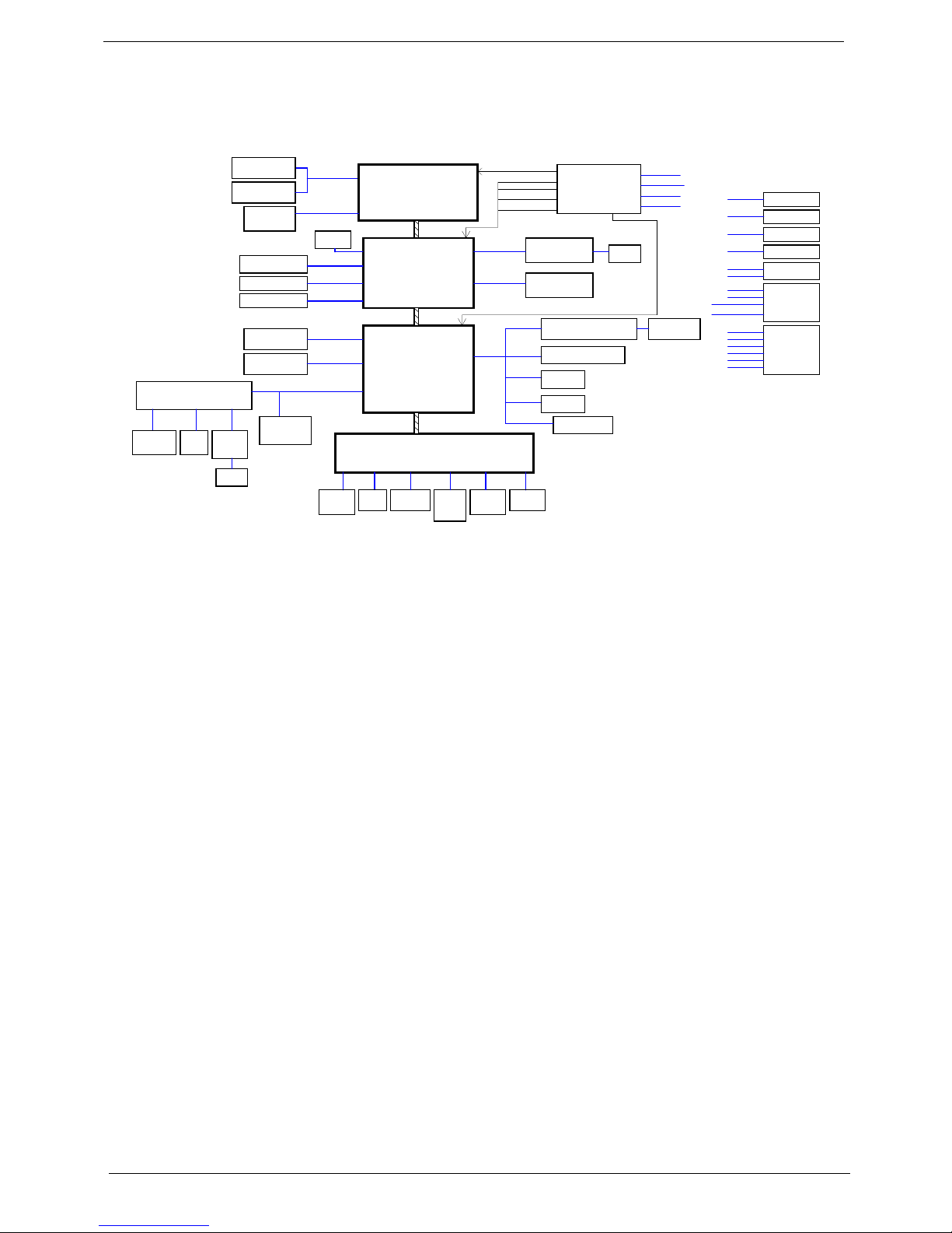
System Block Diagram
DDRII-SODIMM1
DDRII-SODIMM2
CRT
SATA- HDD
Mini Card (WLAN)
SATA0
3V/5V
AMD S1g1
Azalia
WPCE775
A_LINK (X4)
LPC
EC
+3VPCU
+3V_S5
+3V
+5VPCU
+1.8VSUS
SMDDR
+1.8VSUS
+1.8V
+SMDDR_VTERM
+1.2V
+1.2V
+1.2V_S5
CPU CORE
VCC_C ORE
Keyboard
Giga LAN
SATA- ODD
SATA4
Azal ia Aud io Code c
+3VSUS
FAN
RJ45
USB2.0
+5V
+2.5V
+1.5V
NB CORE
+1.5V
+2.5V
(1.0~1.1V)
Touch
Pad
Flash
ROM
SPI
MIC
JACK
HP+SPDF
JACK
USB2.0 I/O Ports X1
+NB_CORE
PCIE 0
Card Reader controller
Card Reader
PG 4,5,6
PG 9,10,11,12
LVDS Panel(LED)
PG 18
LVDS(1ch)
AMP
Speaker
CX20561-15z
G1441
RTS5159E
BCM5784M
PG 24
MODEM CONN.
(MDC)
+3.3V_SUS
800 MHZ
NB
SB
PG 7,8
PG 7,8
PG 18
PCIE 3
PG 13,14,15,16,17
PG 20
PG 20 PG 20 PG 20
PG 20
PG 21 PG 21
PG 22
BT CONN.
PG 22
PG 23 PG 23
PG 24
PG 24
PG 25
PG 25
PG 26
PG 25
PG 26
PG 8
+1.2V
+SMDDR_VTERM
PG 8
+3V
CPU THERMAL
SENSOR
+2.5V
VCC_CORE
+1.8VSUS
+1.8VSUS
+1.8VSUS
+1.8V
+3V
+1.2V
+NB_CORE
+1.2V
+1.8V
VCCRTC
+3V_S5
+3V
+1.2V_S5
+5V
+3V
+5V
+3V
VIN
+3V
+3V
+5V
+5V
+3V_S5
+3V
+1.5V
+3VSUS
+3V
+5V
+3V
+5V
POWER/B
PG 25
+3VPCU +5V
PG 18
WEBCAM
+5VPCU
+3V
+3VPCU
+3VPCU
+3V
PG 26
MMB/B
+3V
+SMDDR_VREF
+SMDDR_VREF
+SMDDR_VREF
Caspian Processor
(638 S1g1 socket)
SB710
RS780MN
21mm X 21mm, 528pin BGA
21mm X 21mm, 528pin BGA
Side port
PG 9
CPU_CLK
NBGFX_CLK
NBGPP_CLK
SBLINK_CLK
CLOCK GENERATOR
HOST 200MHz
PCIE 100MHz
USB 48MHz
REF 14MHz
ICS9LPRS476AKLFT
SLG8SP628VTR
RTM880N-795
PG 3
HDMI
PG 19
SBSRC_CLK
+1.1V_NB
+5V
GFX_TX0-3
USBP8
USBP4
USBP10
USBP5
DDR II 667 M HZ
HT_LINK(1.0)
HTREF_CLK
+3V
USB2.0 Board
USBP0;USBP1
Chapter 1 5
Gateway Notebook tour
This section contains information about the external features and functions of the computer.
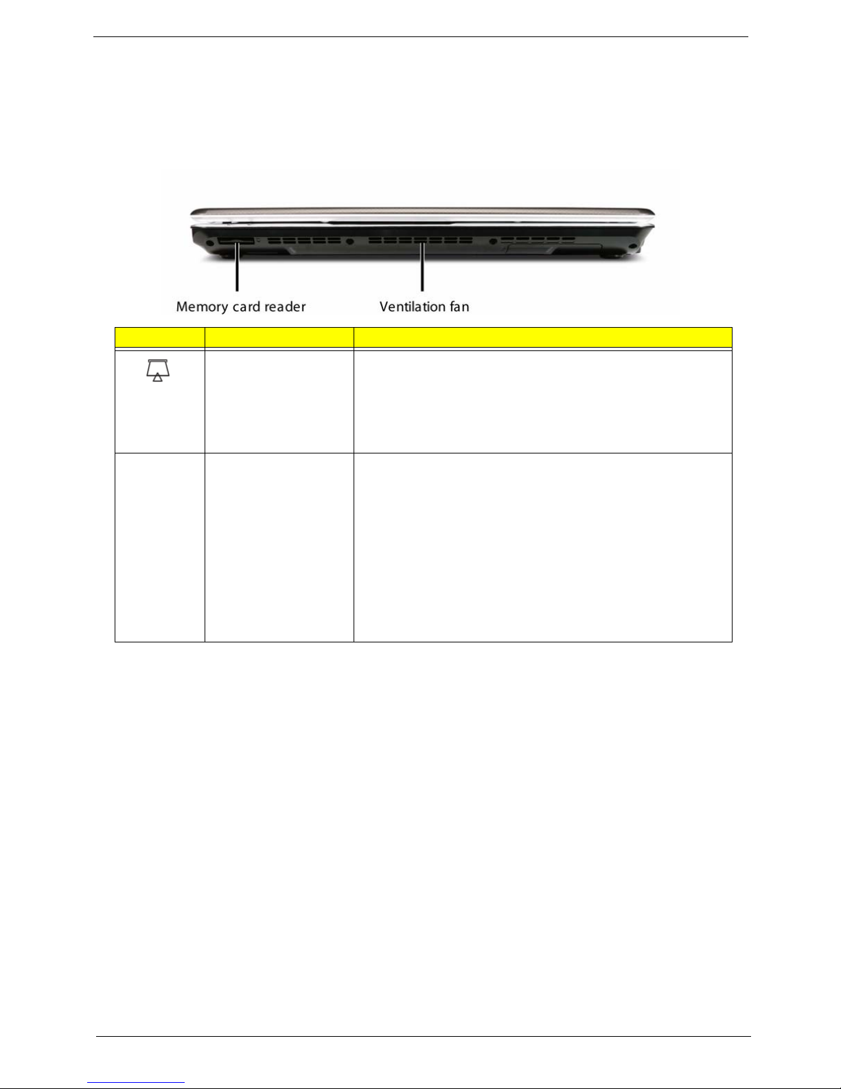
Front View
Icon Item Description
Memory card reader Insert a memory card from a digital camera, MP3 player, PDA,
or cellular telephone into the memory card reader.
The memory card reader supports Memory Stick®, Memory
Stick Pro®, Mini Secure Digital®, MultiMediaCard™, RSMultiMediaCard™, Secure Digital™, and xD-Picture Card™
cards.
Ventilation fan Helps cool internal components.
Warning: Do not work with the notebook resting on your lap. If
the air vents are blocked, the notebook may become hot
enough to harm your skin.
Caution: Do not block or insert objects into these slots. If
these slots are blocked, your notebook may overheat resulting
in unexpected shutdown or permanent damage to the
notebook.
Caution: Provide adequate space around your notebook so
air vents are not obstructed. Do not use the notebook on a
bed, sofa, rug, or other similar surface.
6 Chapter 1
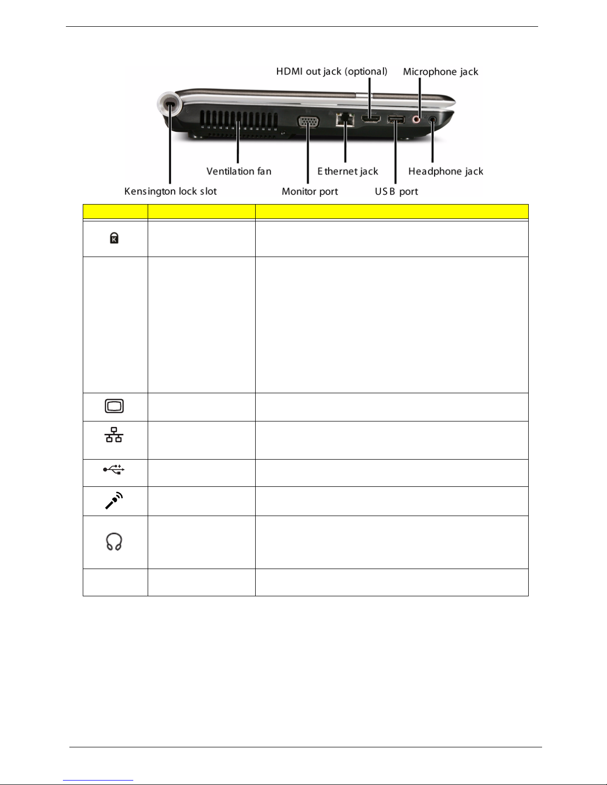
Left View
Icon Item Description
Kensington™ lock
slot
Secure your notebook to an object by connecting a
Kensington cable lock to this slot.
Ventilation fan Helps cool internal components.
Warning: Do not work with the notebook resting on your lap. If
the air vents are blocked, the notebook may become hot
enough to harm your skin.
Caution: Do not block or insert objects into these slots. If
these slots are blocked, your notebook may overheat resulting
in unexpected shutdown or permanent damage to the
notebook.
Caution: Provide adequate space around your notebook so
air vents are not obstructed. Do not use the notebook on a
bed, sofa, rug, or other similar surface.
Monitor port Plug an analog VGA monitor or projector into this port.
Ethernet jack Plug an Ethernet network cable into this jack. Plug the other
end of the cable into a cable modem, DSL modem, or an
Ethernet network jack.
USB port Plug USB devices (such as a diskette drive, flash drive, printer,
scanner, camera, keyboard, or mouse) into this port.
Microphone jack Plug a microphone into this jack.
Headphone jack Plug amplified speakers or headphones into this jack. The
built-in speakers are turned off when speakers or headphones
are plugged into this jacks.
• Headphone with SPDIF support
HDMI HDMI out jack
(optional)
Plug an HDMI device, such as a high definition television, into
this optional jack.

Chapter 1 7
Right View
Rear View
Icon Item Description
DVD drive Insert CDs or DVDs into this drive.
USB ports Plug USB devices (such as a diskette drive, flash drive, printer,
scanner, camera, keyboard, or mouse) into these ports.
Power indicator Press to turn the power on or off. You can also configure the
power button for Sleep/Resume mode.
Icon Item Description
Battery Provides power when the notebook is not plugged into AC
power.
Modem jack (optional) Plug a dial-up modem cable into this optional jack.
Power connector Plug the AC adapter cable into this connector.
8 Chapter 1
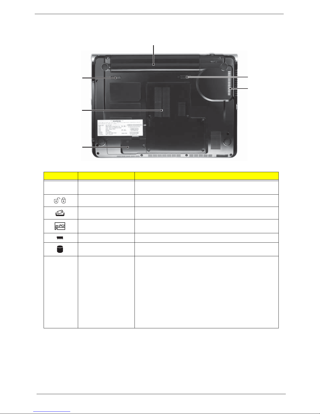
Bottom View
Icon Item Description
Battery Provides power when the notebook is not plugged into AC
power.
Battery lock Slide to unlock the battery.
Battery latch Slide to release the battery.
MicroPCI bay MicroPCI modules are located in this bay.
Memory bay Memory modules are located in this bay.
Hard drive bay The hard drive is located in this bay.
Ventilation slots and
cooling fan
Helps cool internal components.
Warning: Do not work with the notebook resting on your lap. If
the air vents are blocked, the notebook may become hot
enough to harm your skin.
Caution: Do not block or insert objects into these slots. If
these slots are blocked, your notebook may overheat resulting
in unexpected shutdown or permanent damage to the
notebook.
Caution: Provide adequate space around your notebook so
air vents are not obstructed. Do not use the notebook on a
bed, sofa, rug, or other similar surface.
Ventilation
slots and
cooling fan
Battery
Battery
latch
Battery
lock
Memory/
Hard drive bay
MicroPCI
bay
Chapter 1 9
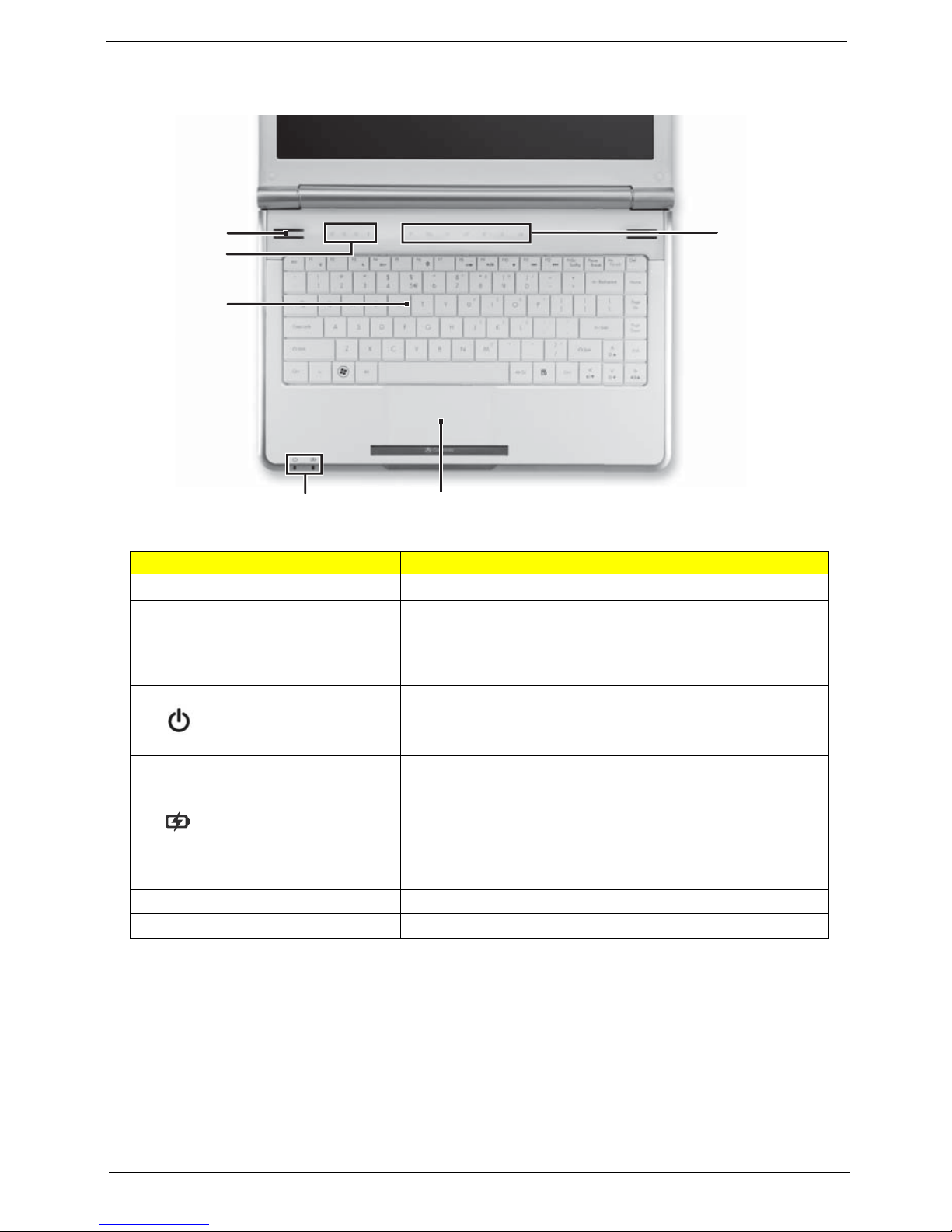
Keyboard Area (selected models)
Icon Item Description
Speakers Left and right speaker deliver stereo output.
Status indicators Inform you when a drive is in use or when a button has been
pressed that affects how the keyboard is used. See “Status
Indicators” on page 11.
Keyboard Provides all the features of a full-sized, computer keyboard.
Power indicator • LED on - Notebook is on.
• LED blinking - Notebook is in Sleep or Hybrid Sleep mode.
• LED off - Notebook is off.
Battery charge
indicator
• LED orange - Battery is fully charged.
• LED blinking orange - Battery is charging.
• LED blinking red - Battery charge is very low.
• LED solid red - Battery is malfunctioning.
Important: This LED only lights up when your notebook is
connected to AC power or the battery charge is very low.
TouchPad Provides all the functionality of a mouse.
Capacitive touch keys Press to access capacitive touch key function.
Keyboard
Capacitive
touch keys
Status
indicators
Speakers
Touchpad
Power/Battery
indicators
10 Chapter 1
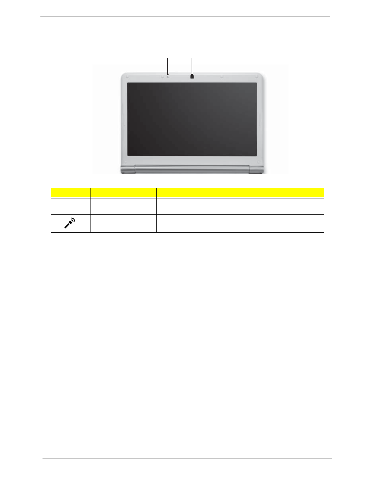
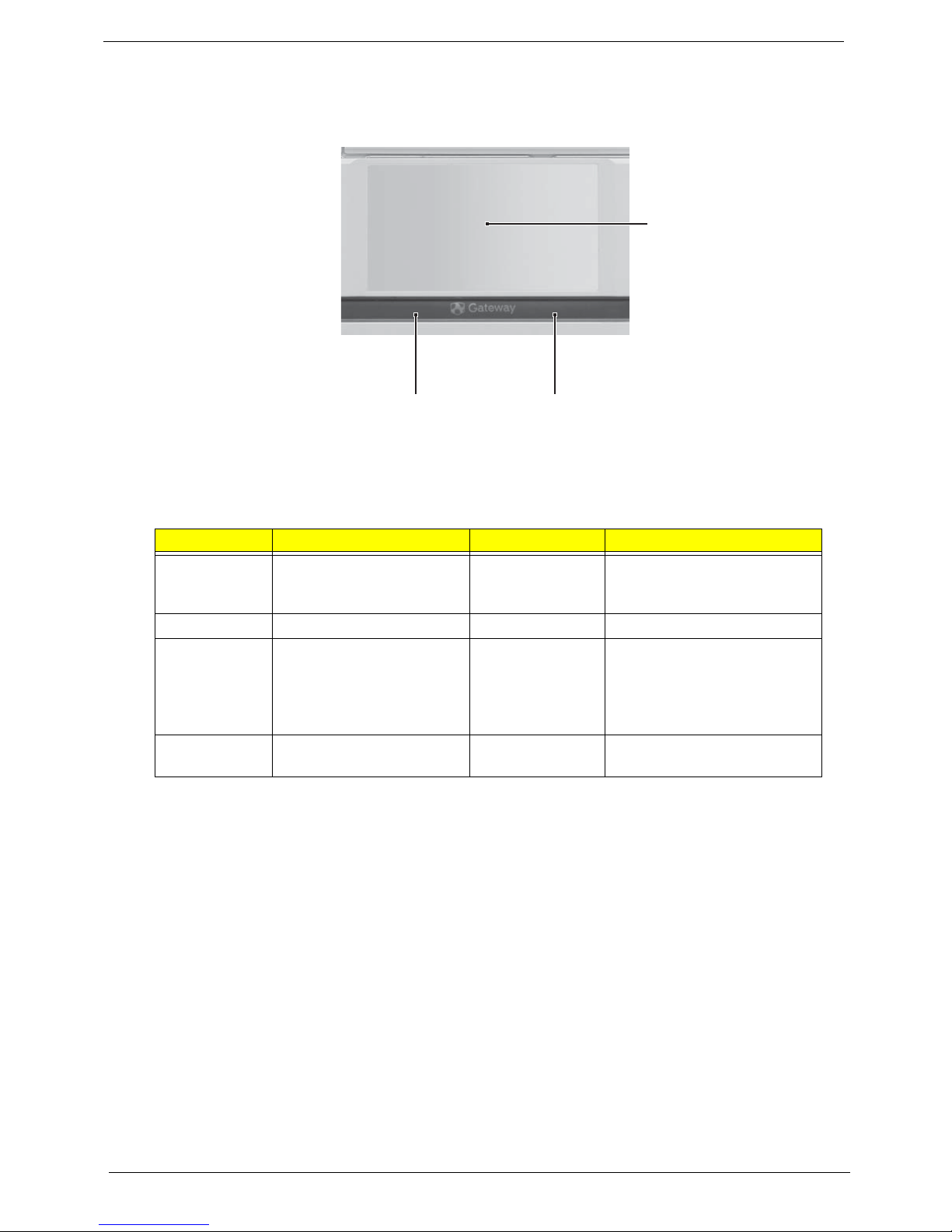
LCD Panel
Icon Item Description
Webcam Use to let others see who they are communicating with when
making VoIP calls.
Microphone Use to talk through when making Voice over Internet Protocol
(VoIP) calls.
Webcam
Microphone
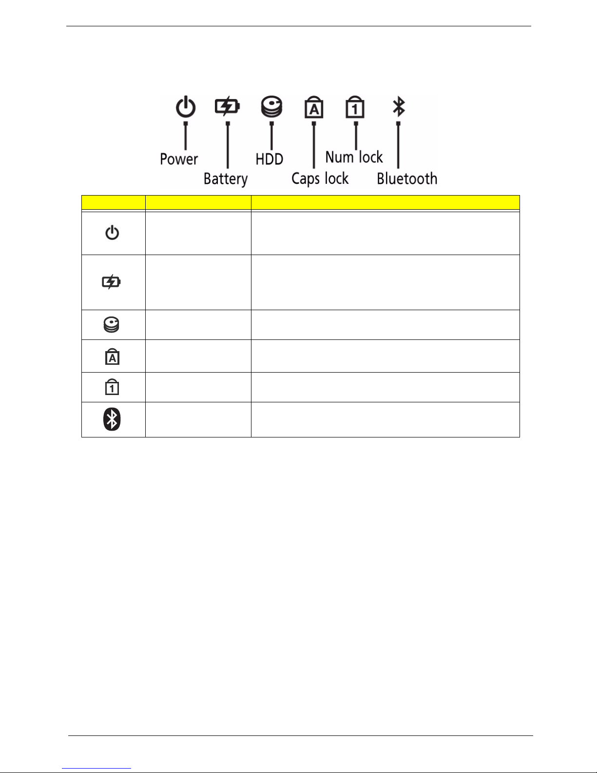
Chapter 1 11
Status Indicators
The computer has several easy-to-read status indicators. The front panel indicators are visible even when the
computer cover is closed.
Icon Item Description
Power indicator • LED on - Notebook is on.
• LED blinking - Notebook is in Sleep or Hybrid Sleep mode.
• LED off - Notebook is off.
Battery charge
indicator
• LED blue - Battery is fully charged.
• LED red - Battery is charging.
Important: This LED only lights up when your notebook is
connected to AC power.
Hard drive • LED blinking - The drive is being accessed.
• LED off - The drive is not being accessed.
Caps lock • LED on - Caps lock is turned on.
• LED off - Caps lock is turned off.
Num lock • LED on - Num lock is turned on.
• LED off - Num lock is turned off.
Bluetooth • LED on - Bluetooth communication is turned on.
• LED off - Bluetooth communication is turned off.
12 Chapter 1
TouchPad Basics
The following items show you how to use the TouchPad:
• Move your finger across the TouchPad to move the cursor.
• Press the left and right buttons located beneath the TouchPad to perform selection and execution
functions. These two buttons are similar to the left and right buttons on a mouse. Tapping on the
TouchPad is the same as clicking the left button.
NOTE: When using the TouchPad, keep it - and your fingers - dry and clean. The TouchPad is sensitive to
finger movement; hence, the lighter the touch, the better the response. Tapping too hard will not
increase the TouchPad’s responsiveness.
Function Left Button Right Button Main T ouchPad
Execute Quickly click twice. Tap twice (at the same speed
as double-clicking a mouse
button).
Select Click once. Tap once.
Drag Click and hold, then use
finger on the TouchPad to
drag the cursor.
Tap twice (at the same speed
as double-clicking a mouse
button); rest your finger on
the TouchPad on the second
tap and drag the cursor.
Access
context menu
Click once.
Left button
Right button
Touchpad
Chapter 1 13
Using the Keyboard
Your Gateway NV42 has a close-to-full-sized keyboard and an embedded numeric keypad, separate cursor,
lock, function and special keys.
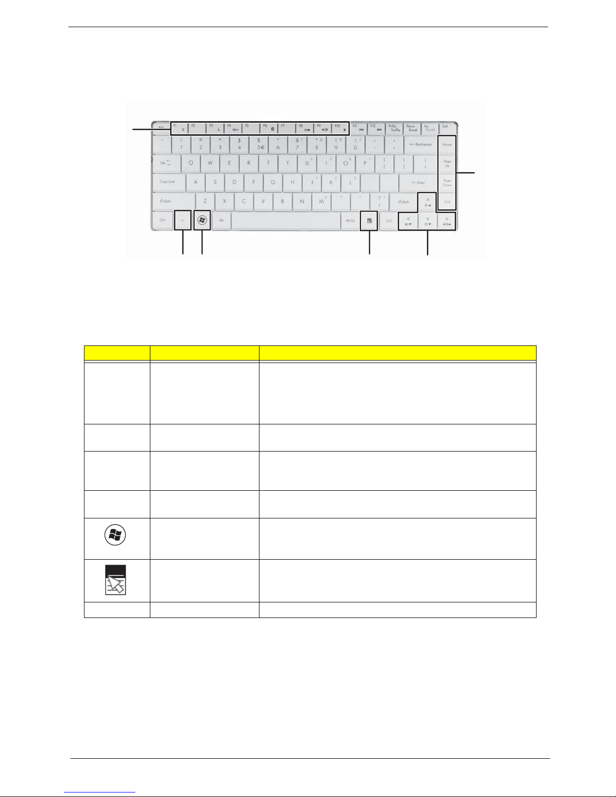
Key Types
The keyboard has several different types of keys. Some keys perform specific actions when pressed alone
and other actions when pressed in combination with another key.
Icon Key Type Description
Function keys Press these keys labeled F1 to F12 to perform actions in
programs. For example, pressing F1 may open help. Each
program uses different function keys for different purposes.
See the program documentation to find out more about the
function key actions.
System keys Press these colored keys in combination with the Fn key to
perform specific actions. See “System Keys” on page 15.
Navigation keys Press these keys to move the cursor to the beginning of a line,
to the end of a line, up the page, down the page, to the
beginning of a document, or to the end of a document.
Fn key Press the Fn key in combination with a colored system key to
perform a specific action.
Windows key Press this key to open the Windows Start menu. This key
can also be used in combination with other keys to open
utilities. See “Windows Keys” on page 14.
Application key Press this key for quick access to shortcut menus and help
assistants in Windows.
Arrow keys Press these keys to move the cursor up, down, right, or left.
Function
keys/
System
keys
FN
key
Windows key
Application key
Arrow keys
Navigation
keys
14 Chapter 1
Windows Keys
The keyboard has two keys that perform Windows-specific functions.
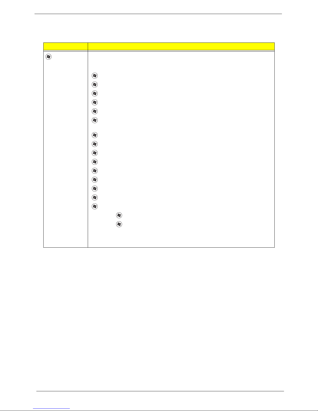
Key Description
Windows key Pressed alone, this key has the same effect as clicking on the Windows Start button;
it launches the Start menu. It can also be used with other keys to provide a variety of
functions:
<>: Open or close the Start menu
<> + <D>: Display the desktop
<> + <E>: Open Windows Explore
<> + <F>: Search for a file or folder
<> + <G>: Cycle through Sidebar gadgets
<> + <L>: Lock your computer (if you are connected to a network domain), or
switch users (if you're not connected to a network domain)
<> + <M>: Minimizes all windows
<> + <R>: Open the Run dialog box
<> + <T>: Cycle through programs on the taskbar
<> + <U>: Open Ease of Access Center
<> + <X>: Open Windows Mobility Center
<> + <BREAK>: Display the System Properties dialog box
<> + <SHIFT+M>: Restore minimized windows to the desktop
<> + <TAB>: Cycle through programs on the taskbar by using Windows Flip 3-D
<> + <SPACEBAR>: Bring all gadgets to the front and select Windows Sidebar
<CTRL> +
<> + <F>: Search for computers (if you are on a network)
<CTRL> + <> + <TAB>: Use the arrow keys to cycle through programs on the
taskbar by using Windows Flip 3-D
Note: Depending on your edition of Windows Vista, some shortcuts may not function
as described.
Chapter 1 15
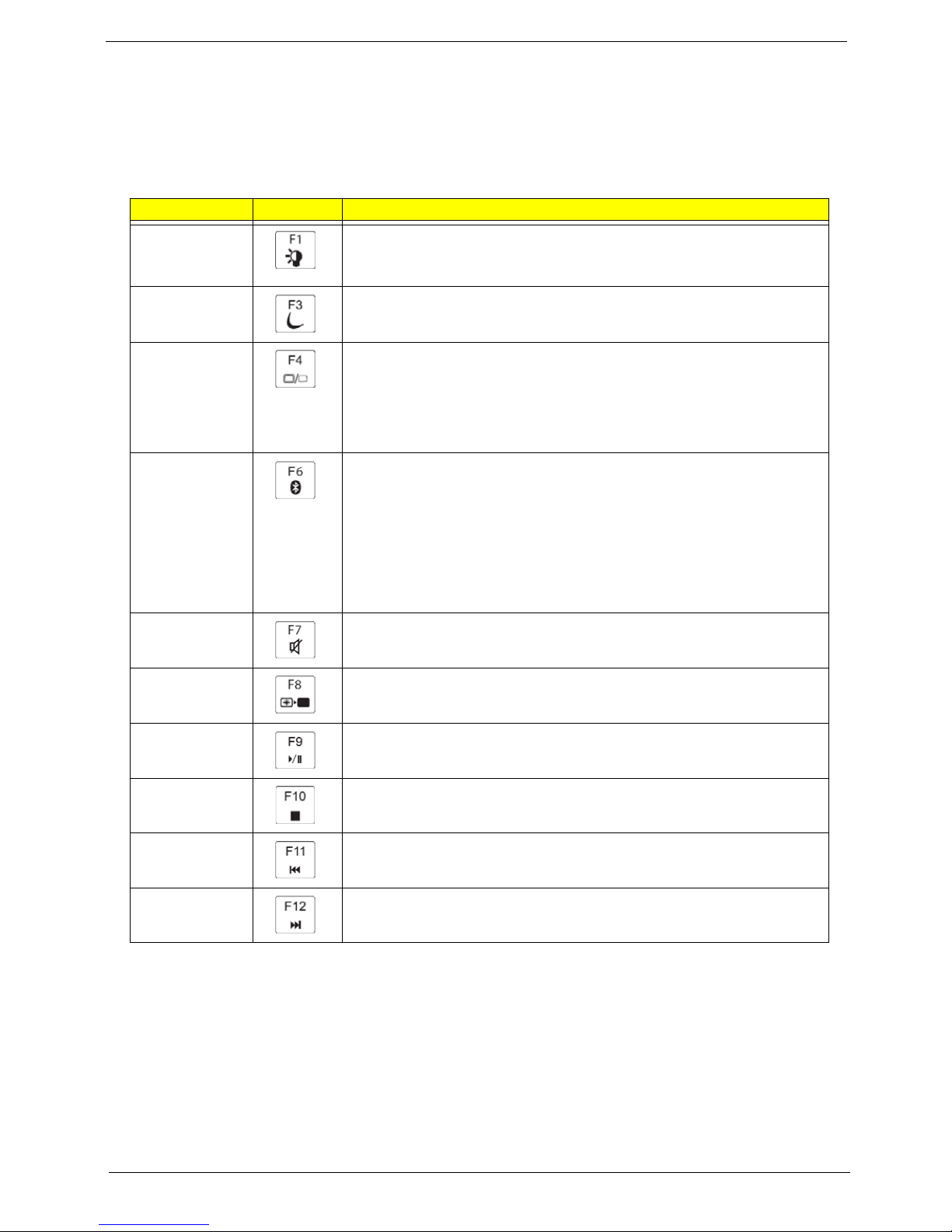
System Keys
The computer employs hotkeys or key combinations to access most of the computer’s controls like screen
brightness, Bluetooth and WiFi.
To activate hot keys, press and hold the <Fn> key before pressing the other key in the hotkey combination.
Hotkey Icon Description
Fn + F1 Turn the capacitive touch key LEDs on or off. For more information, see
“Using the status indicators” on page 24.
Fn + F3 Enter Sleep mode or Hybrid Sleep mode. Press the power button to leave
Sleep mode.
Fn + F4 Toggle the notebook display in the following order:
• The LCD
• An external monitor or projector (a monitor or projector must be
plugged into the monitor port or HDMI port on your notebook)
• Both displays at the same time
Fn + F6 Turn the optional Bluetooth radio on or off.
Warning: Radio frequency wireless communication can interfere with
equipment on commercial aircraft.
Current aviation regulations require wireless devices to be turned off
while traveling in an airplane. Bluetooth communication devices are
examples of devices that provide wireless communication.
Important: The wireless network switch must be in the ON position for
this button to work.
Fn + F7 Mute the sound. Press the key combination again to restore the sound.
Fn + F8 Turns the display screen backlight off to save power. Press any key to
return.
Fn + F9 Play/ Pause—Plays or pauses the CD or DVD.
Fn + F10 Stop—Stops playing the CD or DVD.
Fn + F11 Previous—Skips back one CD track or DVD chapter.
Fn + 12 Next—Skips ahead one CD track or DVD chapter.
16 Chapter 1
Hardware Specifications and Configurations
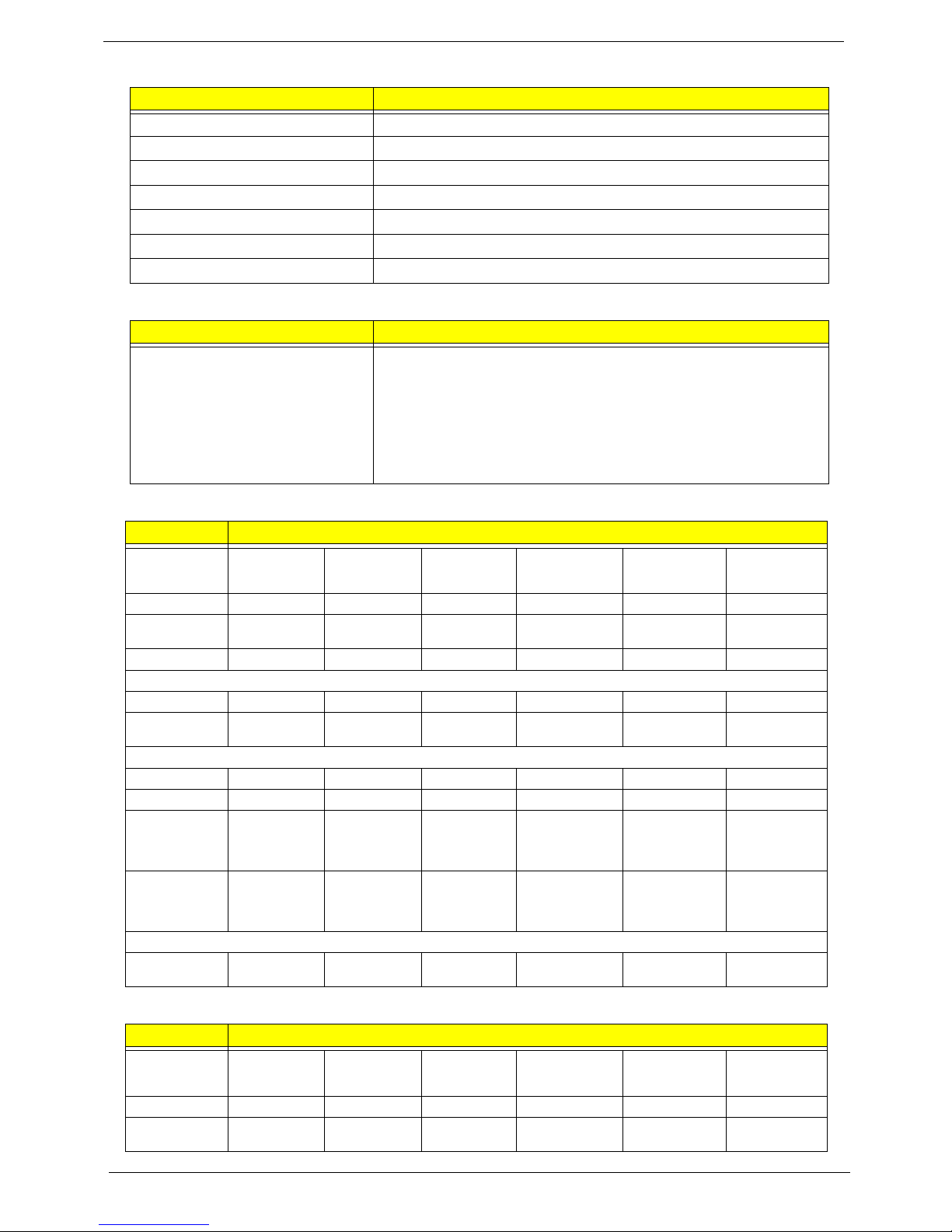
Processor
Processor Specifications
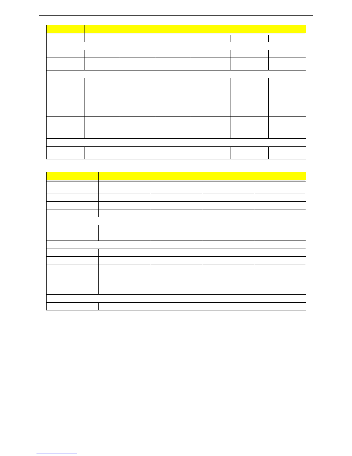
CPU Fan Tru Value Table
• Throttling 50%: On= 84°C; OFF=86°C
• OS shut down at 100°C; H/W shut down(PH1) at 110°C
Item Specification
CPU type AMD Turion/Sempron
CPU package Micro-PGA packaging, 638-pin
Core Logic • AMD Turion/Sempron CPUs
•RS780MN
• SB710
Chipset • WPCE775 integrated power controller and keyboard controller
• Integrated RS780MN VGA chip.
Features • Supports the mobile and desktop Athlon 64/Athlon 64FX/
Athlon X2/Sempron/Turion 64 processors, including S1 socket
CPUs.
• Support for DDR2 system memories up to DDR2-667, with a
maximum memory clock speed of 667MHz.
• Integrated VGA.
• One x4 A-Link Express II interface (PCI Express 1.1 compliant)
for connection to an AMD Southbridge.
• Support PCI bus at 33MHz.
• Supports four SATA ports, complying with the SATA 1.0a
specification
• 5 OHCI and 1 EHCI Host controllers to support 12 USB ports
Item
CPU
Speed
Cores
Bus
Speed
(MHz)
Mfg.
Tech
Cache
Size
Package Acer P/N
Athlon
TF20
1.6 GHz 1 65 nm 512 kB S1 KC.ATF02.200
Athlon
TF36
2.0 GHz 1 256 kB S1 KC.ATF02.360
Athlon
TF38
2.2 GHz 1 256 kB S1 KC.ATF02.380
AthlonX2
TK42
1.6 GHz 2 65 nm 1 MB S1 KC.ATK02.420
CPU Temperature at
Diode (°C)
Fan Speed (RPM) SPL Spec (dBA)
33 38 2700 28
40 45 3000 31
52 47 3300 34
60 67 3800 37
72 75 4000 40
92 89 4800
Chapter 1 17
Graphics
Item Specification
Display support Dual independent display support
Colors 16.7 million colors
External
resolution/refresh
rate
• 2048 x 1536: 75/60 Hz
• 1920 x 1440: 85/75/60 Hz
• 1920 x 1200: 75/60 Hz
• 1920 x 1080: 100/85/75/60 Hz
• 1680 x 945: 100/85/75/60 Hz
• 1600 x 1200: 120/100/85/75/60 Hz
• 1600 x 900: 120/100/85/75/60 Hz
• 1400 x 1050: 85/75/60 Hz
• 1366 x 768: 85/75/60 Hz
• 1280 x 1024: 120/100/85/75/60 Hz
• 1280 x 960: 85/75/60 Hz
• 1280 x 768: 85/75/60 Hz
• 1280 x 720: 100/85/75/60 Hz
• 1024 x 768: 120/100/85/75/60 Hz
• 800 x 600: 120/100/85/72/60 Hz
18 Chapter 1
System Memory
System Storage
Hard Disk Drive Interface
Item Specification
Memory controller Built in
Memory size N/A
DIMM socket number 2
Supports memory size per socket 2 GB
Supports maximum memory size 4 GB
Supports DIMM type DDR II 800/677Mhz SDRAM memory interface design
Supports DIMM Speed 800/677Mhz SDRAM
Item Specification
HDD • 9.5mm height, 2.5" HDD
• Easily removable with no more than four screws
• SATA bus
• 160-500GB
• 5400 rpm
• SATA connector BTO
Item Hard Disk Specification
Vendor &
Model Name
Seagate
ST9160310AS
Seagate
ST9250315AS
Seagate
ST9320320AS
Seagate
ST9500325AS
Hitachi
HTS54
3216L9A300
Hitachi
HTS545025B9
A300
Capacity (GB) 160 250 320 500 160 250
Bytes per
sector
512 512 512 512 512 512
Data heads 2 2 4 4 2 2
Drive Format
Disks 1 1 2 2 1 1
Spindle speed
(RPM)
5400 5400 5400 5400 5400 5400
Performance Specifications
Buffer size 8 MB 8 MB 8MB 8 MB 8 MB 8MB
In ter face SATA SATA S ATA SATA SATA SATA
Fast data
transfer rate
(Mbits/sec,
max)
830
1175 830 1175 845 875
Media data
transfer rate
(Mbytes/sec
max)
300 300 300 300 300 300
DC Power Requirements
Voltage
tolerance
5V ±5% 5V ±5% 5V ±5% 5V ±5% 5V ±5% 5V ±5%
Item Hard Disk Specification
Vendor &
Model Name
Hitachi
HTS545032B9
A300
Hitachi
HTS545050B9
A300
To sh i ba
MK1655GSX
To sh i ba
MK2555GSX
To sh ib a
MK3255GSX
To sh i ba
MK5055GSX
Capacity (GB) 320 500 160 250 320 500
Bytes per
sector
512 512 512 512 512 512
Chapter 1 19
Data heads 2 4 2 2 4 4
Drive Format
Disks 1 2 1 1 2 2
Spindle speed
(RPM)
5400 5400 5400 5400 5400 5400
Performance Specifications
Buffer size 8 MB 8 MB 8MB 8 MB 8 MB 8MB
In ter face SATA SATA S ATA SATA SATA SATA
Fast data
transfer rate
(Mbits/sec,
max)
875 875 363 ~ 952
typical
363 ~ 952
typical
363 ~ 952
typical
363 ~ 952
typical
Media data
transfer rate
(Mbytes/sec
max)
300 300 300 300 300 300
DC Power Requirements
Voltage
tolerance
5V ±5% 5V ±5% 5V ±5% 5V ±5% 5V ±5% 5V ±5%
Item Hard Disk Specification
Vendor & Model Name
Western Digital
WD1600BEVT-22ZCTO
Western Digital
WD2500BEVT-22ZCT0
Western Digital
WD3200BEVT-22ZCT0
Western Digital
WD5000BEVT-22ZAT0
Capacity (GB) 160 250 320 500
Bytes per sector 512 512 512 512
Data heads 2434
Drive Format
Disks1222
Spindle speed (RPM) 5400 5400 5400 5400
Performance Specifications
Buffer size 8 MB 8 MB 8MB 8 MB
In terf ace S ATA SATA S ATA SATA
Fast data transfer rate
(Mbits/sec, max)
N/A N/A N/A N/A
Media data transfer
rate
(Mbytes/sec max)
300 300 300 300
DC Power Requirements
Voltage tolerance 5V ±5% 5V ±5% 5V ±5% 5V ±5%
Item Hard Disk Specification
20 Chapter 1
Optical Disk Drive
BIOS
Item Specification
Type 8X DVD-Super Multi double-layer drive
Performance
Specification
Transfer rate (MB/
sec)
10.8
Buffer Memory 2MB
Read/write speeds ·Read: 24X CD-ROM, 24X CD-R, 24X CD-RW, 8X DVD-ROM, 8X DVD-R, 8X
DVD+R, 6X DVD-ROM DL (double-layer), 6X DVD-R DL (double-layer), 6X
DVD+R DL (double-layer), 6X DVD-RW, 6X DVD+RW, 5X DVD-RAM
·Write: 24X CD-R, 16X CD-RW, 8X DVD-R, 8X DVD+R, 4X DVD-R DL (doublelayer), 4X DVD+R DL (double-layer), 6X DVD-RW, 8X DVD+RW, 5X DVD-RAM
Interface SATA
Loading mechanism Drawer-Type
Power Requirement
Input Voltage DC 5 V +/- 5%
Item Specification
BIOS vendor Phoenix
BIOS Version 2301
BIOS ROM type Flash
BIOS ROM size 16 MB
 Loading...