

Page 1
Page 2

Page 3

Contents
Replacing Gateway Notebook Components . . . . . . . . . . . . . . . . . . . . . . . . . . . . . . 1
Identifying the notebook model . . . . . . . . . . . . . . . . . . . . . . . . . . . . . . . . . . . . . . . . . . . . . . . 2
Identifying components . . . . . . . . . . . . . . . . . . . . . . . . . . . . . . . . . . . . . . . . . . . . . . . . . . . . . 3
Preparing your work space . . . . . . . . . . . . . . . . . . . . . . . . . . . . . . . . . . . . . . . . . . . . . . . . . . 4
Preventing static electricity discharge . . . . . . . . . . . . . . . . . . . . . . . . . . . . . . . . . . . . . . . . . . 5
Preparing the notebook . . . . . . . . . . . . . . . . . . . . . . . . . . . . . . . . . . . . . . . . . . . . . . . . . . . . . 6
Removing the battery . . . . . . . . . . . . . . . . . . . . . . . . . . . . . . . . . . . . . . . . . . . . . . . . . . . 7
Replacing the memory module in the memory bay . . . . . . . . . . . . . . . . . . . . . . . . . . . . . . . 8
Replacing the IEEE 802.11 Mini PCI card . . . . . . . . . . . . . . . . . . . . . . . . . . . . . . . . . . . . . 13
Replacing the hard drive kit . . . . . . . . . . . . . . . . . . . . . . . . . . . . . . . . . . . . . . . . . . . . . . . . . 20
Replacing the hard drive in the hard drive kit . . . . . . . . . . . . . . . . . . . . . . . . . . . . . . . . . . . 23
Replacing the CD or DVD drive . . . . . . . . . . . . . . . . . . . . . . . . . . . . . . . . . . . . . . . . . . . . . 26
Replacing the keyboard cover . . . . . . . . . . . . . . . . . . . . . . . . . . . . . . . . . . . . . . . . . . . . . . . 28
Replacing the keyboard . . . . . . . . . . . . . . . . . . . . . . . . . . . . . . . . . . . . . . . . . . . . . . . . . . . . 32
Replacing the cooling assembly . . . . . . . . . . . . . . . . . . . . . . . . . . . . . . . . . . . . . . . . . . . . . 36
Replacing the processor . . . . . . . . . . . . . . . . . . . . . . . . . . . . . . . . . . . . . . . . . . . . . . . . . . . 42
Replacing the LCD panel assembly . . . . . . . . . . . . . . . . . . . . . . . . . . . . . . . . . . . . . . . . . . 45
Replacing the LCD panel inverter . . . . . . . . . . . . . . . . . . . . . . . . . . . . . . . . . . . . . . . . . . . . 52
Replacing the LCD panel or LCD panel lid . . . . . . . . . . . . . . . . . . . . . . . . . . . . . . . . . . . . . 57
Replacing the palm rest assembly . . . . . . . . . . . . . . . . . . . . . . . . . . . . . . . . . . . . . . . . . . . 60
Replacing the CMOS battery . . . . . . . . . . . . . . . . . . . . . . . . . . . . . . . . . . . . . . . . . . . . . . . . 64
Replacing the modem . . . . . . . . . . . . . . . . . . . . . . . . . . . . . . . . . . . . . . . . . . . . . . . . . . . . . 67
Replacing the speakers . . . . . . . . . . . . . . . . . . . . . . . . . . . . . . . . . . . . . . . . . . . . . . . . . . . . 71
Replacing the memory card reader . . . . . . . . . . . . . . . . . . . . . . . . . . . . . . . . . . . . . . . . . . . 75
Replacing the memory module under the palm rest . . . . . . . . . . . . . . . . . . . . . . . . . . . . . . 80
Replacing the system board . . . . . . . . . . . . . . . . . . . . . . . . . . . . . . . . . . . . . . . . . . . . . . . . 84
www.gateway.com
i
Page 4

ii
www.gateway.com
Page 5

Replacing Gateway Notebook Components
Important This service guide is not intended to be
provided to individual users or consumers.
It cannot be provided to anyone other than
an authorized service provider.
Use this service guide to help plan maintenance tasks for
the Gateway 7000 series, M520, MX7000, and NX700
notebook. All tasks covered in this guide can be
performed by an authorized field technician without
jeopardizing the notebook’s warranty.
Important For information on the notebook’s general
maintenance, technical support, safety
notices, and regulatory notices, see the
Gateway user guide.
Important If you have suggestions regarding the
content of this guide, send an e-mail with
the subject “Service Guide Comments” to
channel.services@gateway.com
.
1
Page 6
Replacing Gateway Notebook Components
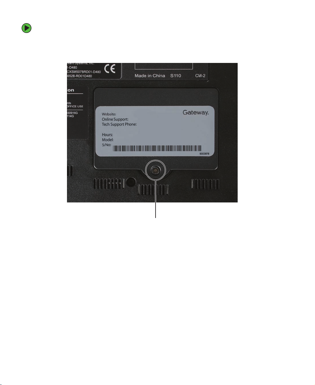
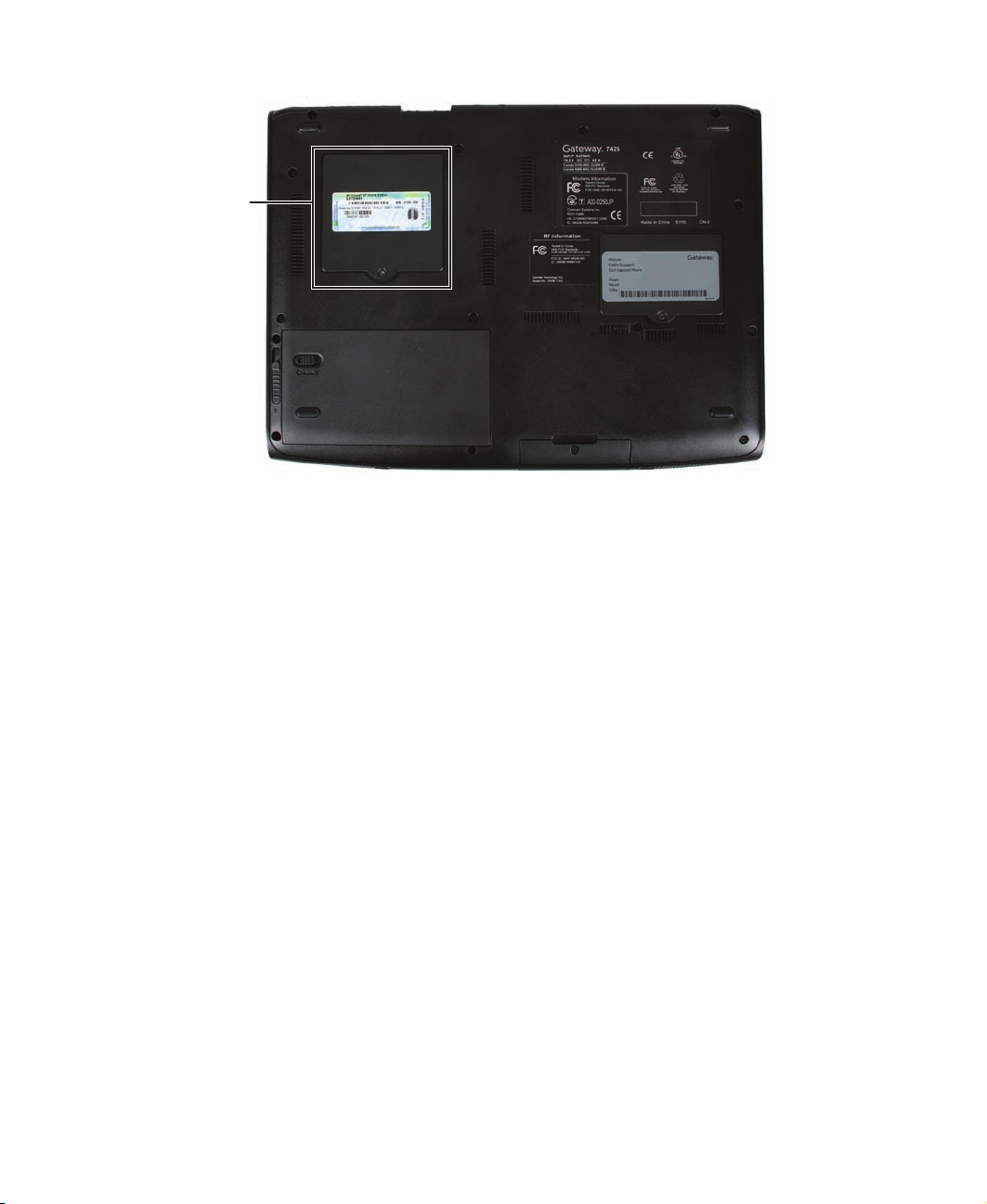
Identifying the notebook model
The label on the bottom of the notebook contains information that identifies the notebook
model and its features.
Caution It is important that you use the correct service guide for the notebook.
Failure to follow the approved tasks for the notebook model may result
in damage to the notebook.
2
www.gateway.com
Page 7
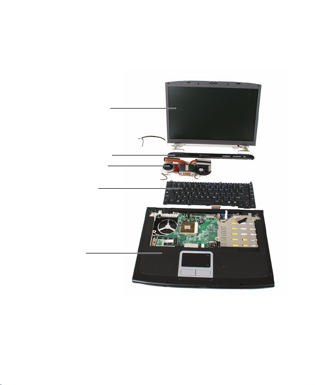
Identifying components
Identifying components
Use this chart to identify the main components of the notebook. For a complete list of
replaceable parts, see “Contents” on page i.
LCD panel assembly
(see page 45)
Keyboard cover
(see page 28)
Cooling assembly
(see page 36)
Keyboard
(see page 32)
Palm rest assembly
(see page 60)
www.gateway.com
3
Page 8

Replacing Gateway Notebook Components
Preparing your work space
Before performing maintenance on the notebook, make sure that your work space and
the notebook are correctly prepared.
■ Wear a grounding (ESD) wrist strap, and use a grounded or dissipative work mat.
■ Use a stable and strong table, and make sure that the table top is large enough to
hold each component as you remove it.
■ Use bright lighting to make part identification easier.
■ Keep your work surface free from clutter and dust that may damage components.
■ Use a magnetized screwdriver for removing screws.
■ When removing components that are attached to the notebook by a cable, unplug
the cable before removing the screws, when possible, to avoid damaging the cable.
■ As you remove components and screws, lay them toward the rear of your work
surface (behind the notebook) or far enough to the side that your arms do not
accidentally brush them onto the floor.
■ To help keep track of screws, try the following:
■ Place each component’s screws in their own section of a parts sorter.
■ Place each component’s screws next to the component on your work surface.
■ Print the first page of each task, then place the page toward the rear of your
work surface. As you remove screws, place the screws in their respective boxes
on the page. Where screw measurements are shown, the first number indicates
screw head width, and the second number indicates screw length.
■ After loosening screws that are deeply recessed in a hole (for example, on the
bottom of the base assembly), you can leave the screws in the holes if you place
small pieces of masking tape over the hole openings. When reassembling the
component, just remove the tape and tighten the screws.
■ When you place flat-headed screws on your work surface, stand them on their
heads to prevent the screws from rolling off the table.
4
www.gateway.com
Page 9
Preventing static electricity discharge
Preventing static electricity discharge
Important Before performing maintenance on the notebook, you should read
and understand the information in this section.
The components inside your notebook are extremely sensitive to static electricity, also
known as electrostatic discharge (ESD).
Warning To avoid exposure to dangerous electrical voltages and moving parts,
turn off your notebook and unplug the power cord, modem cable, and
network cable before opening the case.
Warning To prevent risk of electric shock, do not insert any object into the vent
holes of the notebook.
Before performing maintenance on the notebook, follow these guidelines:
■ Avoid static-causing surfaces such as carpeted floors, plastic, and packing foam.
■ Remove components from their antistatic bags only when you are ready to use
them. Do not lay components on the outside of antistatic bags because only the
inside of the bags provide electrostatic protection.
■ Always hold components by their edges. Avoid touching the edge connectors.
Never slide components over any surface.
■ Wear a grounding wrist strap (available at most electronics stores) and attach it to
a bare metal part of your workbench or other grounded connection.
■ Touch a bare metal surface on your workbench or other grounded object.
Caution Some of the procedures in this guide involve removing tape that holds
wires or components. Two types of tape are used in this Gateway
notebook:
■
Mylar, non-conductive tape is typically transparent, with a red or
brown tint.
■
Conductive tape is typically grey or silver.
If the existing tape cannot be reused, replace it with the same type
(conductivity) of tape. Both types of replacement tape should be
non-ESD generating tape.
Do not use cellophane tape.
www.gateway.com
5
Page 10

Replacing Gateway Notebook Components
Preparing the notebook
Warning To avoid exposure to dangerous electrical voltages and moving parts,
turn off the notebook, remove the battery, and unplug the power cord,
modem cable, and network cable before opening the case. Replace
the cover before you restore power or reconnect the modem and
network cables.
To prepare the notebook for maintenance:
1 Make sure that the CD or DVD drive is empty.
2 Remove any memory cards from the memory card reader.
3 Turn off the notebook and unplug the power cord, modem cable, and network cable.
4 Close the LCD panel.
5 Disconnect all peripheral devices and remove any PC Cards.
6 Remove the battery. For more information, see “Removing the battery” on page 7.
6
www.gateway.com
Page 11
Preparing the notebook
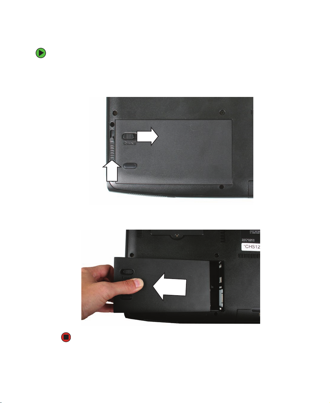
Removing the battery
To remove the battery:
1 Turn the notebook over so the bottom is facing up.
2 Slide the battery lock to the unlocked position, then slide and hold the battery release
latch.
3 Lift the battery out of the bay.
www.gateway.com
7
Page 12
Replacing Gateway Notebook Components
Replacing the memory module in the memory bay
Important Use only memory modules designed for the Gateway 7000 series,
M520, MX7000, or NX700.
Important This notebook has two memory modules. One is located in the
memory bay. The other is accessible only after removing the palm
rest. For more information, see “Replacing the memory module under
the palm rest” on page 80.
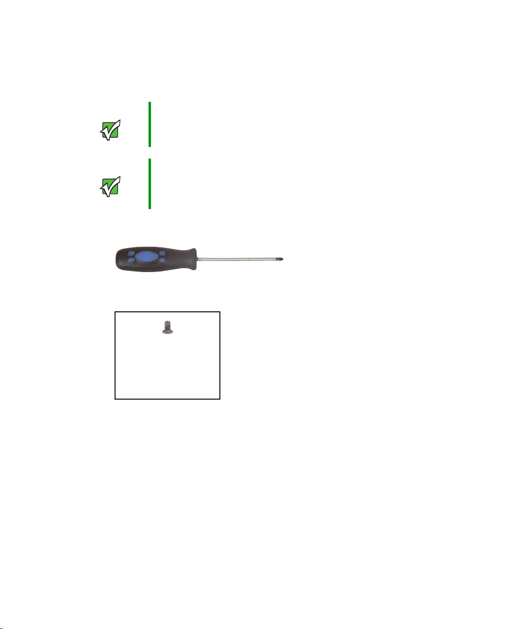
Tools you need to complete this task:
Phillips #0 screwdriver
Screws removed during this task:
1 black (memory bay
cover)
8
www.gateway.com
Page 13

Replacing the memory module in the memory bay
Memory bay
www.gateway.com
9
Page 14
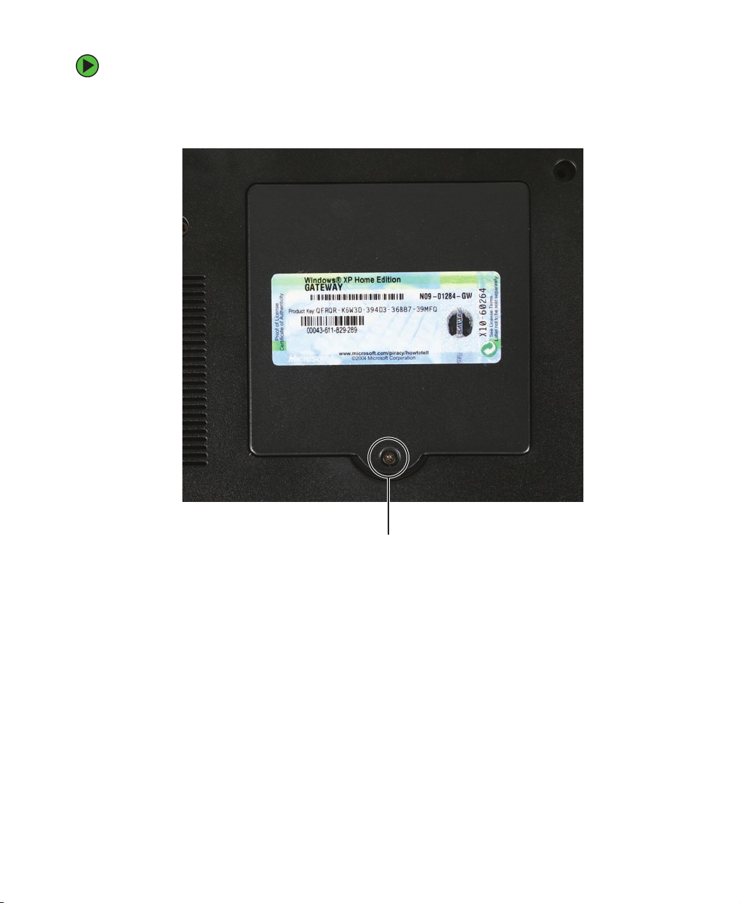
Replacing Gateway Notebook Components
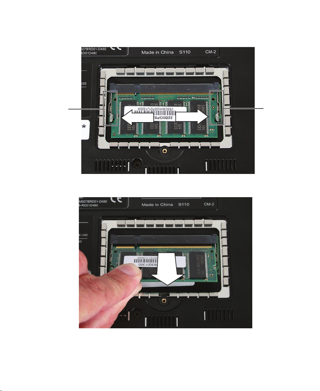
To replace the memory module:
1 Complete the steps in “Preparing the notebook” on page 6.
2 Remove the memory bay cover screw.
3 Open the memory bay cover, then remove it.
10
www.gateway.com
Screw
Page 15
Replacing the memory module in the memory bay
4 Gently press outward on the clip at each end of the memory module until the module
tilts upward.
Clip
5 Pull the memory module out of the slot.
Clip
www.gateway.com
11
Page 16

Replacing Gateway Notebook Components
6 Hold the replacement module at a 30-degree angle and press it into the empty memory
slot. This module is keyed so it can only be inserted in one direction. If the module
does not fit, make sure that the notch in the module lines up with the tab in the
memory bay.
Important Use only memory modules designed for the Gateway 7000 series,
M520, MX7000, or NX700.
7 Gently push the module down until it clicks in place.
8 Replace the memory bay cover, then replace the cover screw.
12
www.gateway.com
Page 17
Replacing the IEEE 802.11 Mini PCI card
Replacing the IEEE 802.11 Mini PCI card
Caution By law, only approved wireless modules provided by Gateway, or a
Gateway authorized representative, explicitly for the Gateway 7000
series, M520, MX7000, or NX700 may be installed in this notebook.
Caution Legal requirements dictate the mini PCI cover plate be in place during
any and all operation of the notebook’s wireless feature.
Tools you need to complete this task:
Phillips #0 screwdriver
Screws removed during this task:
1 black (mini PCI bay
cover)
www.gateway.com
13
Page 18
Replacing Gateway Notebook Components
Mini PCI
bay
14
www.gateway.com
Page 19
Replacing the IEEE 802.11 Mini PCI card
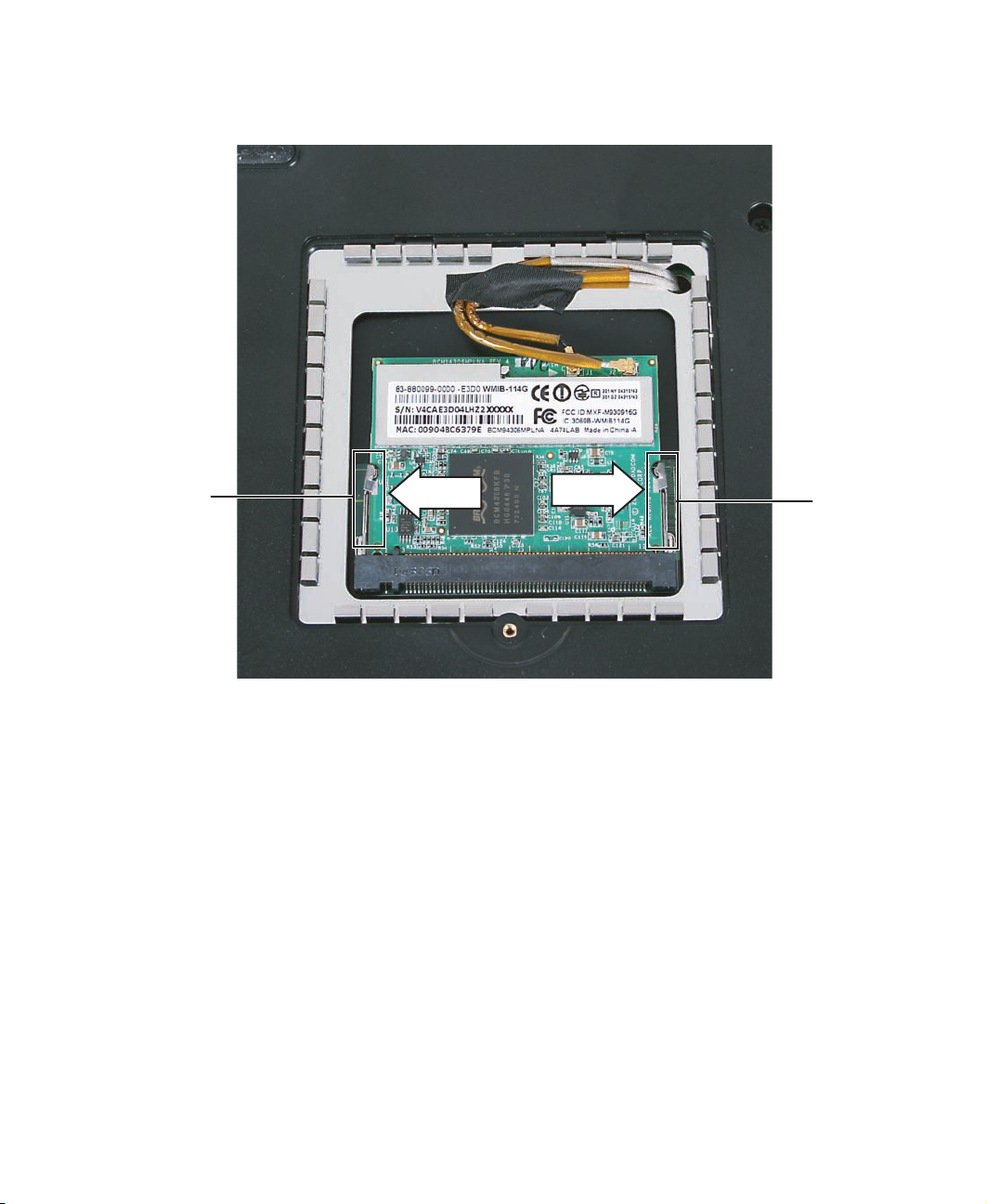
To replace the IEEE 802.11 Mini PCI card:
1 Complete the steps in “Preparing the notebook” on page 6.
2 Remove the mini PCI bay cover screw.
Screw
3 Open the mini PCI bay cover, then remove it.
www.gateway.com
15
Page 20

Replacing Gateway Notebook Components
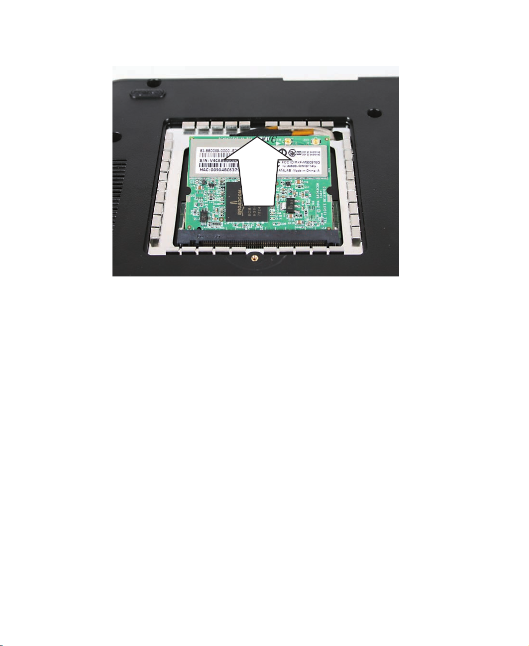
4 Note which antenna cable is attached to the connector labelled MAIN or M, and which
antenna cable is attached to the connector labelled AUX or A.
Tips & Tricks Wrap one of the wires with a piece of tape to help remind you.
5 Unplug the two antenna cables.
16
www.gateway.com
Page 21
Replacing the IEEE 802.11 Mini PCI card
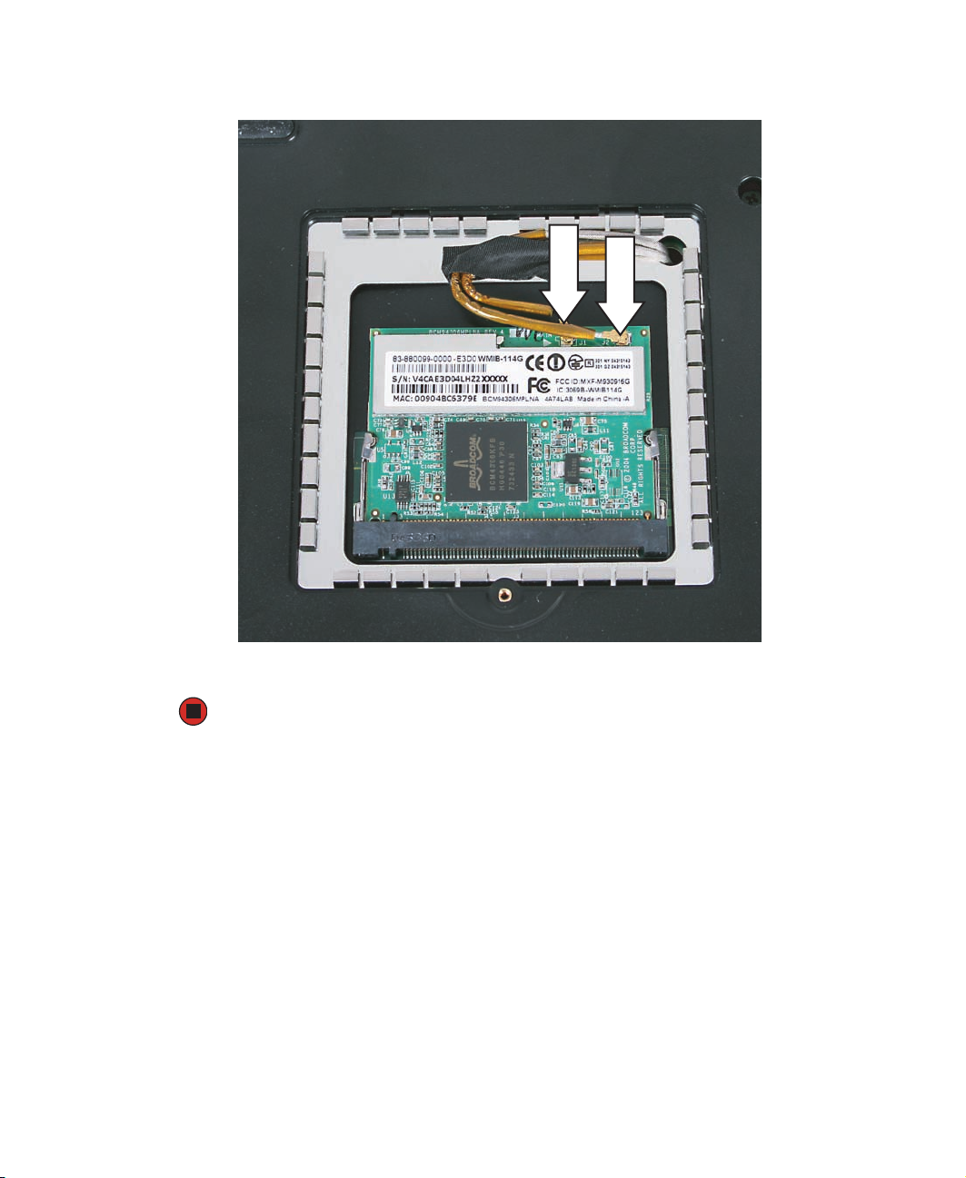
6 Move the antenna cables out of the way, then press outward on the clip at each side
of the module until the module tilts upward.
Clip
Clip
www.gateway.com
17
Page 22
Replacing Gateway Notebook Components
7 Pull the module out of the slot.
8 Hold the new module at a 30-degree angle and press it into the empty slot. This
module is keyed so it can only be inserted in one direction. If the module does not
fit, make sure that the notch in the module lines up with the tab in the module slot.
9 Move the antenna cables out of the way, then press the module down until it clicks
into place.
18
www.gateway.com
Page 23
Replacing the IEEE 802.11 Mini PCI card
10 Reattach the antenna cable to the connectors noted in Step 4.
11 Replace the wireless network bay cover, then replace the cover screw.
www.gateway.com
19
Page 24
Replacing Gateway Notebook Components
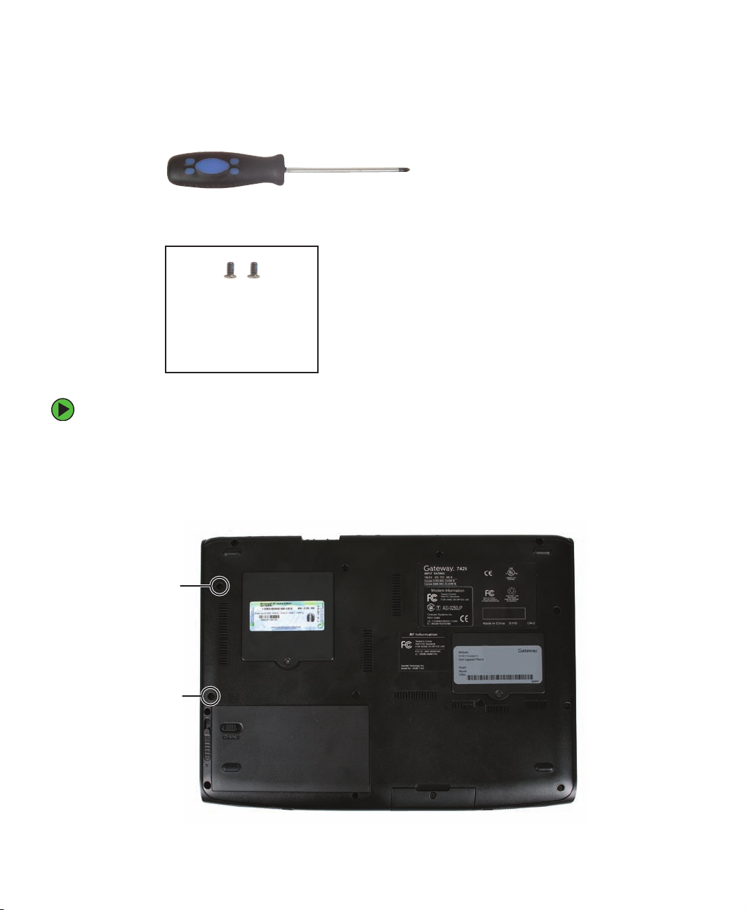
Replacing the hard drive kit
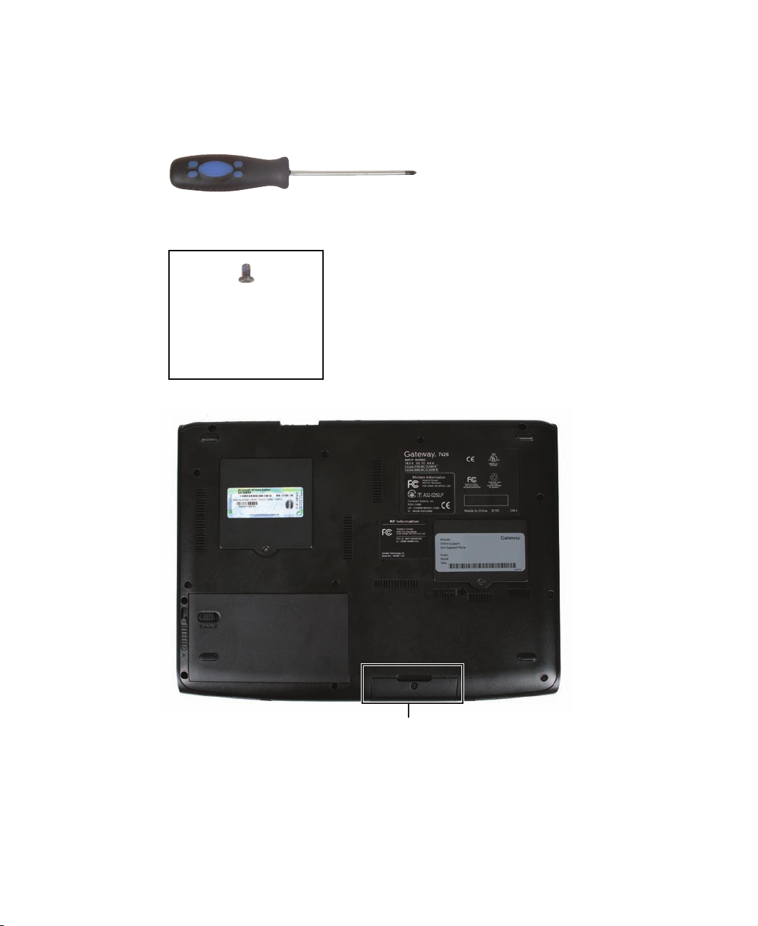
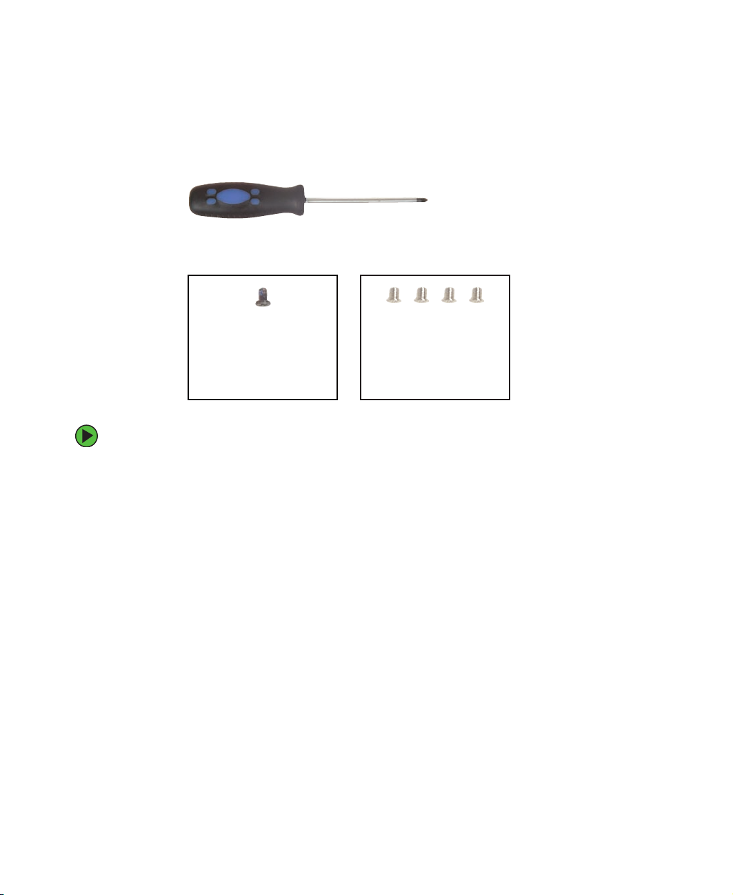
Tools you need to complete this task:
Phillips #0 screwdriver
Screws removed during this task:
1 black (hard drive kit)
20
Hard drive bay
www.gateway.com
Page 25
Replacing the hard drive kit
To replace the hard drive kit:
1 Create a Drivers and Applications Recovery disc using the procedure found in the Using
Gateway System Recovery online guide. To access this guide, click
System Recovery, then click Recovery Help Manual.
Start, All Programs,
2 Print the Using Gateway System Recovery online guide for use in Step 8.
3 Back up any data you want to transfer to the new hard drive. For more information,
see “Backing up files” in Using Your Computer which has been included on your hard
drive. To access this guide, click
Start, All Programs, then click Gateway Documentation.
4 Complete the steps in “Preparing the notebook” on page 6.
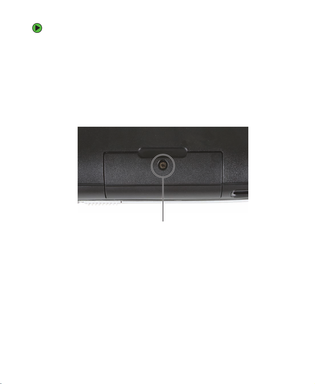
5 Remove the hard drive kit screw.
Screw
www.gateway.com
21
Page 26
Replacing Gateway Notebook Components
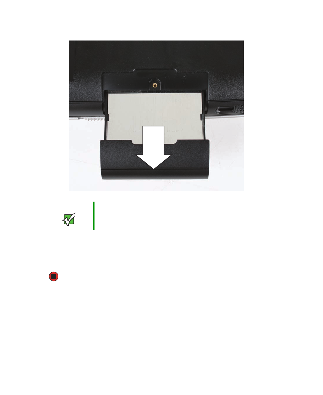
6 Slide the hard drive bay kit to remove it.
Important If your new hard drive does not include the hard drive kit bracket,
complete the steps in “Replacing the hard drive in the hard drive kit”
on page 23 before proceeding.
7 Slide the new hard drive kit into your notebook, then replace the screw that secures
the hard drive kit to your notebook.
8 For instructions on installing Windows, your drivers, and your applications, see the
Using Gateway System Recovery online guide you printed in Step 2.
22
www.gateway.com
Page 27
Replacing the hard drive in the hard drive kit
Replacing the hard drive in the hard drive
kit
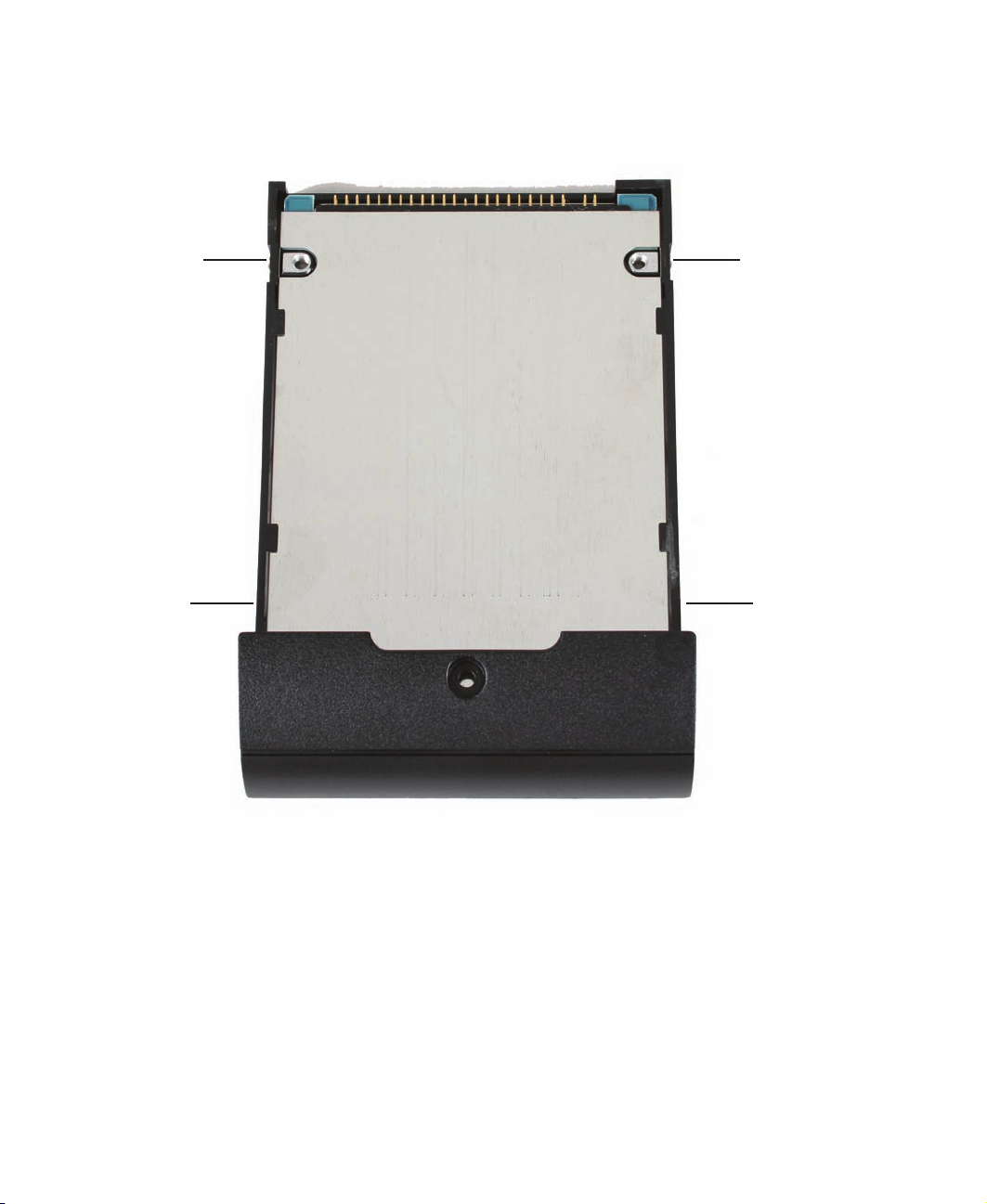
Tools you need to complete this task:
Phillips #0 screwdriver
Screws removed during this task:
1 black (hard drive kit)
To replace the hard drive in the hard drive kit:
4 chrome (hard drive)
1 Complete the steps in “Preparing the notebook” on page 6.
2 Remove the hard drive kit by following the instructions in “Replacing the hard drive
kit” on page 20.
www.gateway.com
23
Page 28
Replacing Gateway Notebook Components
3 Remove the four screws that secure the hard drive to the hard drive kit bracket.
Screw
Screw
Screw
Screw
24
www.gateway.com
Page 29
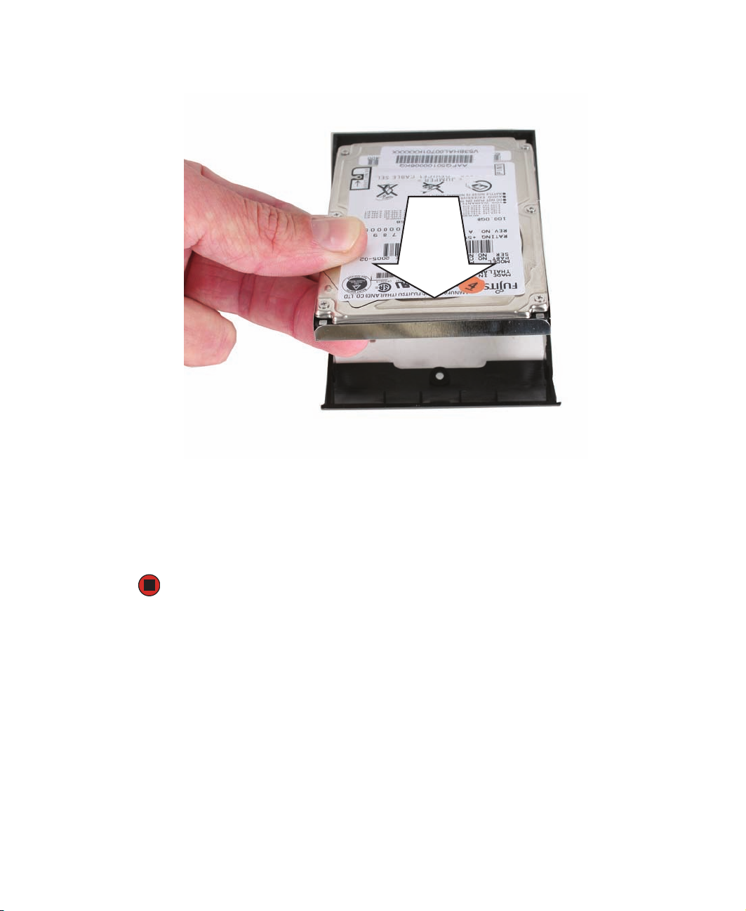
4 Remove the bracket from the old drive.
Replacing the hard drive in the hard drive kit
5 Insert the new drive into the bracket with the label side up and so the screw holes
line up.
6 Replace the four screws that secure the bracket to the drive.
7 Reassemble the notebook.
www.gateway.com
25
Page 30
Replacing Gateway Notebook Components
Replacing the CD or DVD drive
Tools you need to complete this task:
Phillips #0 screwdriver
Screws removed during this task:
2 black (CD or DVD
drive)
To replace the CD or DVD drive:
1 Complete the steps in “Preparing the notebook” on page 6.
2 Turn the notebook over so the bottom is facing up.
3 Remove the two CD or DVD drive screws.
Screw
Screw
26
www.gateway.com
Page 31

Replacing the CD or DVD drive
4 Insert a straightened paper clip into the CD or DVD drive’s manual eject hole, push
in the paper clip to eject the drive tray, then pull the drive tray open.
5 Carefully slide the drive out of the drive bay.
6 Slide the new CD or DVD drive into the drive bay. Make sure that the drive fits securely
in the bay.
7 Secure the CD or DVD drive with the two screws removed in Step 3.
www.gateway.com
27
Page 32

Replacing Gateway Notebook Components
Replacing the keyboard cover
Tools you need to complete this task:
Flat-blade driver Scribe or non-marring tool
Phillips #0 screwdriver
Screws removed during this task:
2 black (keyboard cover)
- OR -
28
www.gateway.com
Page 33

Replacing the keyboard cover
To replace the keyboard cover:
1 Complete the steps in “Preparing the notebook” on page 6.
2 Remove the two keyboard cover screws.
Screw Screw
3 Turn the notebook over so the top is facing up.
4 Open the LCD panel to the fully open position.
5 Insert the small flat-blade screwdriver under the bottom of each hinge cover and
gently loosen them.
www.gateway.com
29
Page 34

Replacing Gateway Notebook Components
6 Insert the small flat-blade screwdriver under the bottom of the keyboard cover and
gently pry it up.
Tips & Tricks Inserting a piece of cloth between the screwdriver and keyboard will
help prevent damage to the notebook.
7 Lift the back edge of the keyboard cover, then rotate it toward you so it lies face-down
on top of the keyboard. Be careful not to damage the LCD panel.
30
www.gateway.com
Page 35

Replacing the keyboard cover
8 Slide the brown power button/multi-function buttons connector clip up, then remove
the cable. Be careful not to touch or damage any other components.
Connector
9 Lift the old keyboard cover away from the notebook. The keyboard cover is now
completely detached from the notebook.
10 Make sure that the brown power button/multi-function buttons connector clip is
pushed up, insert the cable from the new keyboard cover into the connector, then
slide the clip downward to lock the connector in place.
11 Place the new keyboard cover on the notebook. Press down on the cover in several
places until it clicks in place.
12 Press down on the hinge covers until they click in place.
The keyboard cover is correctly mounted when you can run your finger along the
cover and find no loose spots. The cover should be flat all the way across.
Caution If the cover is not correctly replaced, the notebook could be damaged
when you try to close the LCD panel.
13 Secure the keyboard cover with the two screws removed in Step 2.
www.gateway.com
31
Page 36

Replacing Gateway Notebook Components
Replacing the keyboard
Tools you need to complete this task:
Flat-blade driver Scribe or non-marring tool
Phillips #0 screwdriver
Screws removed during this task:
2 black (keyboard cover)
2 black (keyboard)
- OR -
To replace the keyboard:
1 Complete the steps in “Preparing the notebook” on page 6.
2 Open the keyboard cover by following the instructions in “Replacing the keyboard
cover” on page 28.
Important You do not need to remove the cover.
3 Remove the two keyboard screws.
Screw Screw
32
www.gateway.com
Page 37

Replacing the keyboard
4 Lift the back edge of the keyboard slightly, then carefully push it toward the LCD
panel to release the keyboard retaining tabs. Be careful not to damage the LCD panel.
5 Lay the keyboard face down on the palm rest.
www.gateway.com
33
Page 38

Replacing Gateway Notebook Components
6 Lift the brown keyboard connector clip and remove the keyboard cable. Be careful
not to touch or damage any other components.
Keyboard
connector
clip
7 Lift the old keyboard away from the notebook. The keyboard is now completely
detached from the notebook.
8 Lay the new keyboard face down on top of the palm rest.
9 Make sure that the brown keyboard connector clip is raised, insert the cable into the
connector, then slide the clip down to lock the connector in place.
Important The cable is correctly oriented if the cable is not twisted.
34
www.gateway.com
Page 39

Replacing the keyboard
10 Insert the tabs on the front edge of the keyboard into the slot under the palm rest.
It may be necessary to press down on the keyboard keys along the front edge of the
keyboard to seat the retaining tabs into their corresponding slots.
11 Gently press the keyboard down until it is flat all the way across. The keyboard should
easily fall into place. Be careful not to damage the LCD panel.
12 Secure the keyboard with the two screws removed in Step 3.
13 Reattach the keyboard cover by following the instructions in “Replacing the keyboard
cover” on page 28.
www.gateway.com
35
Page 40

Replacing Gateway Notebook Components
Replacing the cooling assembly
Tools you need to complete this task:
Phillips #0 screwdriver
Additional materials you need to complete this task:
■ X-23-7762 thermal grease
Screws removed during this task:
2 black (keyboard cover)
1 black (LCD ground
screw)
2 black (keyboard)
4 chrome (cooling
assembly)
4 black (cooling assembly
cover)
To replace the cooling assembly:
1 Complete the steps in “Preparing the notebook” on page 6.
2 Remove the keyboard cover by following the instructions in “Replacing the keyboard
cover” on page 28.
3 Remove the keyboard by following the instructions in “Replacing the keyboard” on
page 32.
36
www.gateway.com
Page 41

4 Remove the cooling assembly cover screws.
Replacing the cooling assembly
Long screw
Short screw
Short screw
Long screw
5 Lift the front of the cooling assembly cover, slide the cover to the front of the
notebook, then remove it.
www.gateway.com
37
Page 42

Replacing Gateway Notebook Components
6 Remove the screw connecting the LCD grounding wire to the top of the number 4
screw.
Grounding screw
7 Remove the four screws that are stamped with the numbers 1 through 4 next to them.
Make sure that you remove the screws in reverse numerical order.
Caution When removing the cooling assembly’s screws from the numbered
holes, remove them in reverse numerical order (4, 3, 2, then 1).
Screw
Screw
Screw
Screw
38
www.gateway.com
Page 43

8 Unplug the old cooling fans.
Connector
Replacing the cooling assembly
Connector
www.gateway.com
39
Page 44

Replacing Gateway Notebook Components
9 Remove the tape from the LCD cable that is taped to the top of the cooling assembly.
10 Lift the cooling assembly up and away from the notebook.
11 Remove any thermal grease residue from the processor using a soft cloth and isopropyl
alcohol.
12 Place new thermal grease on the processor. Use only enough to cover the CPU die.
13 Install the new cooling assembly in the notebook.
14 Plug in the new cooling fans.
15 Replace the four screws that are stamped with the numbers 1 through 4 next to them.
Make sure that you tighten the screws in numerical order.
Caution When tightening the cooling assembly’s screws into the numbered
holes, tighten them in numerical order (1, 2, 3, then 4).
16 Replace the grounding wire and screw removed in Step 6.
40
www.gateway.com
Page 45

Replacing the cooling assembly
17 Replace the LCD cable and tape that was removed in Step 9.
Caution Two types of tape are used in this Gateway notebook:
■
Mylar, non-conductive tape is typically transparent, with a red or
brown tint.
■
Conductive tape is typically grey or silver.
If the existing tape cannot be reused, replace it with the same type
(conductivity) of tape. Both types of replacement tape should be
non-ESD generating tape.
Do not use cellophane tape.
18 Replace the cooling assembly cover, then replace the cover screws.
19 Reassemble the notebook.
www.gateway.com
41
Page 46

Replacing Gateway Notebook Components
Replacing the processor
Tools you need to complete this task:
Phillips #0 screwdriver
Additional materials you need to complete this task:
■ X-23-7762 thermal grease
Screws removed during this task:
2 black (keyboard cover)
1 black (LCD ground
screw)
2 black (keyboard)
4 chrome (cooling
assembly)
4 black (cooling assembly
cover)
To replace the processor:
1 Complete the steps in “Preparing the notebook” on page 6.
2 Remove the keyboard cover by following the instructions in “Replacing the keyboard
cover” on page 28.
3 Remove the keyboard by following the instructions in “Replacing the keyboard” on
page 32.
4 Remove the cooling assembly by following the instructions in “Replacing the cooling
assembly” on page 36.
42
www.gateway.com
Page 47

Replacing the processor
5 Release the processor by pushing down on the lever and then lifting it completely up.
6 Remove the old processor from the system board.
7 Install the new processor onto the system board making sure that Pin 1 on the
processor (indicated by the silk-screened arrow on the corner of the processor) aligns
with Pin 1 on the processor socket (indicated by the absence of a pin hole in the
processor socket), then return the lever to its locked position.
www.gateway.com
43
Page 48

Replacing Gateway Notebook Components
8 Remove any thermal grease residue from the cooling assembly using a soft cloth and
isopropyl alcohol.
9 Place the thermal grease on the processor. Use only enough to cover the CPU die.
10 Reassemble the notebook.
44
www.gateway.com
Page 49

Replacing the LCD panel assembly
Replacing the LCD panel assembly
Tools you need to complete this task:
Flat-blade driver Scribe or non-marring tool- OR -
Phillips #0 screwdriver
Screws removed during this task:
1 black (mini PCI bay
cover)
4 black (cooling assembly
cover)
2 black (LCD panel)
2 black (keyboard cover)
1 black (LCD ground
screw)
2 black (LCD hinges)
2 black (keyboard)
1 black (LCD ground
screw)
www.gateway.com
45
Page 50

Replacing Gateway Notebook Components
To replace the LCD panel assembly:
1 Complete the steps in “Preparing the notebook” on page 6.
2 If the notebook has IEEE 802.11 wireless networking built in, unplug the antenna
cables from the IEEE 802.11 mini PCI card by following the instructions in “Replacing
the IEEE 802.11 Mini PCI card” on page 13.
3 Remove the keyboard cover by following the instructions in “Replacing the keyboard
cover” on page 28.
Caution Use extreme care when opening the LCD panel.
4 Remove the keyboard by following the instructions in “Replacing the keyboard” on
page 32.
5 Remove the cooling assembly cover and LCD panel grounding wire by following the
instructions in “Replacing the cooling assembly” on page 36.
6 Carefully remove the white LCD panel connector by lifting upward using a screw
driver, scribe, or non-marring tool.
46
Connector
www.gateway.com
Page 51

Replacing the LCD panel assembly
7 Remove the screw connecting the LCD grounding wire to the top of the notebook.
Grounding screw
8 Grasp the black plastic sleeve carefully and pull upward to unplug the LCD video cable
from the notebook.
Connector
www.gateway.com
47
Page 52

Replacing Gateway Notebook Components
9 Taking care to note the cables’ routing and positions as they are installed from
Gateway, pull the antenna cables out from under the system board.
Wireless
antenna
access
hole
48
www.gateway.com
Page 53

Replacing the LCD panel assembly
10 Carefully unplug the white LCD panel connector by lifting upward using a screw
driver, scribe, or non-marring tool.
Connector
www.gateway.com
49
Page 54

Replacing Gateway Notebook Components
11 Carefully close the LCD panel, then remove the two screws that secure the LCD panel
to the bottom of the notebook.
Screw
Screw
12 Open the LCD panel, then remove the two hinge screws that secure the LCD panel
to the notebook.
50
Screw
Screw
www.gateway.com
Page 55

Replacing the LCD panel assembly
13 Lift the LCD panel assembly up and away from the notebook. The LCD panel assembly
is now completely detached from the notebook.
14 Place the new LCD panel assembly onto the notebook, then replace the two hinge
screws.
15 Reattach the cable removed in Step 10 to the appropriate connector on the system
board.
16 Slide the antenna cables through the access hole, under the system board, then into
the mini-PCI card area.
17 Plug the LCD video cable removed in Step 8 into the notebook.
18 Replace the grounding wire and screw removed in Step 7.
19 Plug the LCD panel connector removed in Step 6 into the notebook.
20 Reassemble the notebook.
www.gateway.com
51
Page 56

Replacing Gateway Notebook Components
Replacing the LCD panel inverter
Tools you need to complete this task:
Flat-blade driver Scribe or non-marring tool- OR -
Phillips #0 screwdriver
Screws removed during this task:
1 black (mini PCI bay
cover)
4 black (cooling assembly
cover)
2 black (LCD panel)
2 black (keyboard cover)
1 black (LCD ground
screw)
2 black (LCD hinges)
2 black (keyboard)
1 black (LCD ground
screw)
6 black (LCD panel
assembly)
52
www.gateway.com
Page 57

Replacing the LCD panel inverter
To replace the LCD panel inverter:
1 Complete the steps in “Preparing the notebook” on page 6.
2 If the notebook has IEEE 802.11 wireless networking built in, unplug the antenna
cables from the IEEE 802.11 mini PCI card by following the instructions in “Replacing
the IEEE 802.11 Mini PCI card” on page 13.
3 Remove the keyboard cover by following the instructions in “Replacing the keyboard
cover” on page 28.
Caution Use extreme care when opening the LCD panel.
4 Remove the keyboard by following the instructions in “Replacing the keyboard” on
page 32.
5 Remove the LCD panel by following the instructions in “Replacing the LCD panel
assembly” on page 45.
6 Remove the six rubber inserts from the front of the LCD panel assembly.
Insert
InsertInsert Insert
InsertInsert
www.gateway.com
53
Page 58

Replacing Gateway Notebook Components
7 Remove the six screws from the front of the LCD panel assembly.
Screw Screw Screw
Screw Screw
Screw
8 Carefully separate the front and back of the LCD panel assembly.
54
www.gateway.com
Page 59

Replacing the LCD panel inverter
9 Disconnect the connectors from the inverter.
Connector Connector
10 Remove any tape holding the old inverter in place, then remove the inverter from
the front of the LCD panel assembly.
11 Insert the new inverter, replacing any tape that may have been holding the inverter
in place.
Caution Two types of tape are used in this Gateway notebook:
■
Mylar, non-conductive tape is typically transparent, with a red or
brown tint.
■
Conductive tape is typically grey or silver.
If the existing tape cannot be reused, replace it with the same type
(conductivity) of tape. Both types of replacement tape should be
non-ESD generating tape.
Do not use cellophane tape.
12 Reconnect the cables.
www.gateway.com
55
Page 60

Replacing Gateway Notebook Components
13 Press the LCD panel front and back together. Press the two halves together in several
places until they click in place. You should find no loose spots or spots where the
two halves do not meet.
14 Replace the six LCD panel assembly screws removed in Step 7.
15 Replace the six inserts removed in Step 6.
16 Reassemble the notebook.
56
www.gateway.com
Page 61

Replacing the LCD panel or LCD panel lid
Replacing the LCD panel or LCD panel lid
Tools you need to complete this task:
Flat-blade driver Scribe or non-marring tool- OR -
Phillips #0 screwdriver
Screws removed during this task:
1 black (mini PCI bay
cover)
4 black (cooling assembly
cover)
2 black (LCD panel)
2 black (keyboard cover)
1 black (LCD ground
screw)
2 black (LCD hinges)
2 black (keyboard)
1 black (LCD ground
screw)
6 black (LCD panel
assembly)
6 black (LCD panel)
www.gateway.com
57
Page 62

Replacing Gateway Notebook Components
To replace the LCD panel or LCD panel lid:
1 Complete the steps in “Preparing the notebook” on page 6.
2 If the notebook has IEEE 802.11 wireless networking built in, unplug the antenna
cables from the IEEE 802.11 mini PCI card by following the instructions in “Replacing
the IEEE 802.11 Mini PCI card” on page 13.
3 Remove the keyboard cover by following the instructions in “Replacing the keyboard
cover” on page 28.
4 Remove the keyboard by following the instructions in “Replacing the keyboard” on
page 32.
5 Remove the LCD panel by following the instructions in “Replacing the LCD panel
assembly” on page 45.
6 Disconnect the connectors from the inverter by following the steps in “Replacing the
LCD panel inverter” on page 52. You do not need to remove the LCD panel inverter.
7 Remove the six screws that secure the LCD panel to the LCD panel assembly.
Screw
Screw
Screw
Screw
Screw
Screw
8 Place the existing LCD panel into the new LCD panel lid, then replace the six screws.
-OR-
Place the new LCD panel into the existing LCD panel lid, then replace the six screws.
58
www.gateway.com
Page 63

Replacing the LCD panel or LCD panel lid
9 Reconnect the inverter.
10 Replace the six LCD panel assembly screws removed in Step 7.
11 Reassemble the notebook.
www.gateway.com
59
Page 64

Replacing Gateway Notebook Components
Replacing the palm rest assembly
Tools you need to complete this task:
Flat-blade driver Scribe or non-marring tool- OR -
Phillips #0 screwdriver
Screws removed during this task:
1 black (mini PCI bay
cover)
2 black (keyboard cover)
2 black (LCD panel)
1 black (hard drive kit)
2 black (keyboard)
1 black (LCD ground
screw)
2 black (CD or DVD
drive)
4 black (cooling assembly
cover)
1 black (LCD ground
screw)
60
2 black (LCD hinges)
9 black (palm restbottom)
www.gateway.com
5 black (palm rest-top)
Page 65

Replacing the palm rest assembly
To replace the palm rest assembly:
1 Complete the steps in “Preparing the notebook” on page 6.
2 If the notebook has IEEE 802.11 wireless networking built in, unplug the antenna
cables from the IEEE 802.11 mini PCI card by following the instructions in “Replacing
the IEEE 802.11 Mini PCI card” on page 13.
3 Remove the hard drive by following the instructions in “Replacing the hard drive kit”
on page 20.
4 Remove the CD or DVD drive by following the instructions in “Replacing the CD or
DVD drive” on page 26.
5 Remove the keyboard cover by following the instructions in “Replacing the keyboard
cover” on page 28.
6 Remove the keyboard by following the instructions in “Replacing the keyboard” on
page 32.
7 Remove the LCD panel by following the instructions in “Replacing the LCD panel
assembly” on page 45.
8 Remove the 9 black screws from the bottom of the notebook.
Short
screw
Short
screw
Long
screw
Short
screw
www.gateway.com
Short
screw
Long
screw
Long
screw
Long
screw
Long
screw
61
Page 66

Replacing Gateway Notebook Components
9 Remove the five black screws from the top of the notebook.
Short screwShort screw Long screw Long screw
Medium
screw
10 Slide the brown touchpad connector clip upward and remove the touchpad cable. Be
careful not to touch or damage any other components.
Touchpad
connector
62
www.gateway.com
Page 67

Replacing the palm rest assembly
11 Lift the palm rest assembly up and away from the notebook.
12 Place the new palm rest assembly onto the notebook.
13 Make sure that the brown touchpad connector clip on the system board is in the raised
position.
14 Insert the end of the touchpad cable into the connector, then slide the clip down.
15 Replace the top palm rest screws removed in Step 9.
16 Turn the notebook so the bottom is facing up.
17 Replace the black screws on the bottom of the notebook removed in Step 8.
18 Reassemble the notebook.
www.gateway.com
63
Page 68

Replacing Gateway Notebook Components
Replacing the CMOS battery
Tools you need to complete this task:
Flat-blade driver Scribe or non-marring tool- OR -
Phillips #0 screwdriver
Screws removed during this task:
1 black (mini PCI bay
cover)
2 black (keyboard cover)
1 black (LCD ground
screw)
1 black (hard drive kit)
2 black (keyboard)
1 black (LCD ground
screw)
2 black (CD or DVD
drive)
4 black (cooling assembly
cover)
2 black (LCD panel)
64
2 black (LCD hinges)
9 black (palm restbottom)
www.gateway.com
5 black (palm rest-top)
Page 69

Replacing the CMOS battery
To replace the CMOS battery:
1 Complete the steps in “Preparing the notebook” on page 6.
2 If the notebook has IEEE 802.11 wireless networking built in, unplug the antenna
cables from the IEEE 802.11 mini PCI card by following the instructions in “Replacing
the IEEE 802.11 Mini PCI card” on page 13.
3 Remove the hard drive by following the instructions in “Replacing the hard drive kit”
on page 20.
4 Remove the CD or DVD drive by following the instructions in “Replacing the CD or
DVD drive” on page 26.
5 Remove the keyboard cover by following the instructions in “Replacing the keyboard
cover” on page 28.
6 Remove the keyboard by following the instructions in “Replacing the keyboard” on
page 32.
7 Remove the LCD panel by following the instructions in “Replacing the LCD panel
assembly” on page 45.
8 Remove the palm rest by following the instructions in “Replacing the palm rest
assembly” on page 60.
9 Locate the old battery on the system board.
www.gateway.com
65
Page 70

Replacing Gateway Notebook Components
10 Insert the small flat-blade screwdriver or non-marring tool under the old battery and
gently pry it up until it pops out of the socket.
11 Make sure that the positive (+) side of the new battery is facing up, then press the
battery into the socket until it snaps into place.
12 Reassemble the notebook.
66
www.gateway.com
Page 71

Replacing the modem
Tools you need to complete this task:
Flat-blade driver Scribe or non-marring tool- OR -
Phillips #0 screwdriver
Replacing the modem
www.gateway.com
67
Page 72

Replacing Gateway Notebook Components
Screws removed during this task:
1 black (mini PCI bay
cover)
2 black (keyboard cover)
1 black (LCD ground
screw)
1 black (hard drive kit)
2 black (keyboard)
1 black (LCD ground
screw)
2 black (CD or DVD
drive)
4 black (cooling assembly
cover)
2 black (LCD panel)
68
2 black (LCD hinges)
2 black (modem)
9 black (palm restbottom)
www.gateway.com
5 black (palm rest-top)
Page 73

Replacing the modem
To replace the modem:
1 Complete the steps in “Preparing the notebook” on page 6.
2 If the notebook has IEEE 802.11 wireless networking built in, unplug the antenna
cables from the IEEE 802.11 mini PCI card by following the instructions in “Replacing
the IEEE 802.11 Mini PCI card” on page 13.
3 Remove the hard drive by following the instructions in “Replacing the hard drive kit”
on page 20.
4 Remove the CD or DVD drive by following the instructions in “Replacing the CD or
DVD drive” on page 26.
5 Remove the keyboard cover by following the instructions in “Replacing the keyboard
cover” on page 28.
6 Remove the keyboard by following the instructions in “Replacing the keyboard” on
page 32.
7 Remove the LCD panel by following the instructions in “Replacing the LCD panel
assembly” on page 45.
8 Remove the palm rest by following the instructions in “Replacing the palm rest
assembly” on page 60.
9 Remove the screws that secure the modem to the notebook.
Screw Screw
www.gateway.com
69
Page 74

Replacing Gateway Notebook Components
10 Gently lift the modem off the system board. If necessary, gently rock the modem back
and forth while lifting.
Caution Avoid using too much force when removing the modem as this could
damage the modem or system board.
11 Turn the modem over, then unplug the modem cable from the modem.
Connector
12 Install the new modem on the system board
13 Reassemble the notebook.
70
www.gateway.com
Page 75

Replacing the speakers
Tools you need to complete this task:
Flat-blade driver Scribe or non-marring tool- OR -
Phillips #0 screwdriver
Screws removed during this task:
Replacing the speakers
1 black (mini PCI bay
cover)
2 black (keyboard cover)
1 black (LCD ground
screw)
1 black (hard drive kit)
2 black (keyboard)
1 black (LCD ground
screw)
2 black (CD or DVD
drive)
4 black (cooling assembly
cover)
2 black (LCD panel)
2 black (LCD hinges)
9 black (palm restbottom)
www.gateway.com
5 black (palm rest-top)
71
Page 76

Replacing Gateway Notebook Components
To replace the speakers:
1 Complete the steps in “Preparing the notebook” on page 6.
2 If the notebook has IEEE 802.11 wireless networking built in, unplug the antenna
cables from the IEEE 802.11 mini PCI card by following the instructions in “Replacing
the IEEE 802.11 Mini PCI card” on page 13.
3 Remove the hard drive by following the instructions in “Replacing the hard drive kit”
on page 20.
4 Remove the CD or DVD drive by following the instructions in “Replacing the CD or
DVD drive” on page 26.
5 Remove the keyboard cover by following the instructions in “Replacing the keyboard
cover” on page 28.
6 Remove the keyboard by following the instructions in “Replacing the keyboard” on
page 32.
7 Remove the LCD panel by following the instructions in “Replacing the LCD panel
assembly” on page 45.
8 Remove the palm rest by following the instructions in “Replacing the palm rest
assembly” on page 60.
72
www.gateway.com
Page 77

9 Unplug the speakers (one connector) from the system board.
Connector
Replacing the speakers
10 Remove any tape holding the speakers in place, then lift the speakers from the
retaining pins.
www.gateway.com
73
Page 78

Replacing Gateway Notebook Components
11 Place the new speakers on the retaining pins, then replace the tape.
Caution Two types of tape are used in this Gateway notebook:
■
Mylar, non-conductive tape is typically transparent, with a red or
brown tint.
■
Conductive tape is typically grey or silver.
If the existing tape cannot be reused, replace it with the same type
(conductivity) of tape. Both types of replacement tape should be
non-ESD generating tape.
Do not use cellophane tape.
12 Reassemble the notebook.
74
www.gateway.com
Page 79

Replacing the memory card reader
Replacing the memory card reader
Tools you need to complete this task:
Flat-blade driver Scribe or non-marring tool- OR -
Phillips #0 screwdriver
www.gateway.com
75
Page 80

Replacing Gateway Notebook Components
Screws removed during this task:
1 black (mini PCI bay
cover)
2 black (keyboard cover)
1 black (LCD ground
screw)
1 black (hard drive kit)
2 black (keyboard)
1 black (LCD ground
screw)
2 black (CD or DVD
drive)
4 black (cooling assembly
cover)
2 black (LCD panel)
76
2 black (LCD hinges)
3 black (memory card
reader shield)
9 black (palm restbottom)
2 black (memory card
reader)
www.gateway.com
5 black (palm rest-top)
Page 81

Replacing the memory card reader
To replace the memory card reader:
1 Complete the steps in “Preparing the notebook” on page 6.
2 If the notebook has IEEE 802.11 wireless networking built in, unplug the antenna
cables from the IEEE 802.11 mini PCI card by following the instructions in “Replacing
the IEEE 802.11 Mini PCI card” on page 13.
3 Remove the hard drive by following the instructions in “Replacing the hard drive kit”
on page 20.
4 Remove the CD or DVD drive by following the instructions in “Replacing the CD or
DVD drive” on page 26.
5 Remove the keyboard cover by following the instructions in “Replacing the keyboard
cover” on page 28.
6 Remove the keyboard by following the instructions in “Replacing the keyboard” on
page 32.
7 Remove the LCD panel by following the instructions in “Replacing the LCD panel
assembly” on page 45.
8 Remove the palm rest by following the instructions in “Replacing the palm rest
assembly” on page 60.
9 Remove the three memory card reader shield screws, then remove the shield.
Screw
ScrewScrew
www.gateway.com
77
Page 82

Replacing Gateway Notebook Components
10 Remove the two memory card reader screws.
Screw
Screw
11 Carefully slide the memory card reader away from the side of the notebook, then turn
it over.
78
www.gateway.com
Page 83

Replacing the memory card reader
12 Slide the brown memory card reader connector clip upward and remove the memory
card reader cable. Be careful not to touch or damage any other components.
Connector
13 Remove the old memory card reader from the notebook.
14 Place the new memory card reader into the notebook.
15 Make sure that the brown memory card reader connector clip on the system board
is in the raised position.
16 Insert the end of the memory card reader cable into the connector, then slide the
clip down.
17 Slide the memory card reader into the notebook, then replace the two screws in the
memory card reader removed in Step 10.
18 Replace the memory card reader shield, then replace the three screws removed in
Step 9.
19 Reassemble the notebook.
www.gateway.com
79
Page 84

Replacing Gateway Notebook Components
Replacing the memory module under the palm rest
Important Use only memory modules designed for the Gateway 7000 series,
M520, MX7000, or NX700.
Important This notebook has two memory modules. One is located in the
memory bay. The other is accessible only after removing the palm
rest. For more information, “Replacing the memory module in the
memory bay” on page 8.
Tools you need to complete this task:
Flat-blade driver Scribe or non-marring tool- OR -
Phillips #0 screwdriver
80
www.gateway.com
Page 85

Screws removed during this task:
Replacing the memory module under the palm rest
1 black (mini PCI bay
cover)
2 black (keyboard cover)
1 black (LCD ground
screw)
1 black (hard drive kit)
2 black (keyboard)
1 black (LCD ground
screw)
2 black (CD or DVD
drive)
4 black (cooling assembly
cover)
2 black (LCD panel)
2 black (LCD hinges)
3 black (memory card
reader shield)
9 black (palm restbottom)
2 black (memory card
reader)
www.gateway.com
5 black (palm rest-top)
81
Page 86

Replacing Gateway Notebook Components
To replace the memory module:
1 Complete the steps in “Preparing the notebook” on page 6.
2 If the notebook has IEEE 802.11 wireless networking built in, unplug the antenna
cables from the IEEE 802.11 mini PCI card by following the instructions in “Replacing
the IEEE 802.11 Mini PCI card” on page 13.
3 Remove the hard drive by following the instructions in “Replacing the hard drive kit”
on page 20.
4 Remove the CD or DVD drive by following the instructions in “Replacing the CD or
DVD drive” on page 26.
5 Remove the keyboard cover by following the instructions in “Replacing the keyboard
cover” on page 28.
6 Remove the keyboard by following the instructions in “Replacing the keyboard” on
page 32.
7 Remove the LCD panel by following the instructions in “Replacing the LCD panel
assembly” on page 45.
8 Remove the palm rest by following the instructions in “Replacing the palm rest
assembly” on page 60.
9 Remove the memory card reader by following the instructions in “Replacing the
memory card reader” on page 75.
82
www.gateway.com
Page 87

Replacing the memory module under the palm rest
10 Gently press outward on the clip at each end of the memory module until the module
tilts upward.
Clip
Clip
11 Pull the memory module out of the slot.
12 Hold the replacement module at a 30-degree angle and press it into the empty memory
slot. This module is keyed so it can only be inserted in one direction. If the module
does not fit, make sure that the notch in the module lines up with the tab in the
memory bay.
Important Use only memory modules designed for the Gateway 7000 series,
M520, MX7000, or NX700.
13 Gently push the module down until it clicks in place.
14 Reassemble the notebook.
www.gateway.com
83
Page 88

Replacing Gateway Notebook Components
Replacing the system board
Tools you need to complete this task:
Flat-blade driver Scribe or non-marring tool- OR -
Phillips #0 screwdriver
Additional materials you need to complete this task:
■ X-23-7762 thermal grease
Screws removed during this task:
1 black (memory bay
cover)
2 black (CD or DVD
drive)
1 black (mini PCI bay
cover)
2 black (keyboard cover)
5.0 mm hex nutdriver
1 black (hard drive kit)
2 black (keyboard)
84
4 black (cooling assembly
cover)
1 black (LCD ground
screw)
www.gateway.com
1 black (LCD ground
screw)
Page 89

Replacing the system board
2 black (LCD panel)
5 black (palm rest-top)
2 black (memory card
reader)
2 black (LCD hinges)
2 black (modem)
4 black (hard drive cage)
9 black (palm restbottom)
3 black (memory card
reader shield)
2 black (optical drive
rails)
1 black (battery bay
bracket)
2 black (system board)
1 chrome hexnut (system
board)
To replace the system board:
1 Complete the steps in “Preparing the notebook” on page 6.
2 Remove the memory module by following the instructions in “Replacing the memory
module in the memory bay” on page 8.
3 If the notebook has IEEE 802.11 wireless networking built in, unplug the antenna
cables from the IEEE 802.11 mini PCI card by following the instructions in “Replacing
the IEEE 802.11 Mini PCI card” on page 13.
www.gateway.com
85
Page 90

Replacing Gateway Notebook Components
4 Remove the mini PC card by following the instructions in “Replacing the IEEE 802.11
Mini PCI card” on page 13.
5 Remove the hard drive kit by following the instructions in “Replacing the hard drive
kit” on page 20.
6 Remove the CD or DVD drive by following the instructions in “Replacing the CD or
DVD drive” on page 26.
7 Remove the keyboard cover by following the instructions in “Replacing the keyboard
cover” on page 28.
8 Remove the keyboard by following the instructions in “Replacing the keyboard” on
page 32.
9 Remove the cooling assembly by following the instructions in “Replacing the cooling
assembly” on page 36.
10 Remove the processor and install it on the new system board by following the
instructions in “Replacing the processor” on page 42.
11 Remove the LCD panel by following the instructions in “Replacing the LCD panel
assembly” on page 45.
12 Remove the palm rest by following the instructions in “Replacing the palm rest
assembly” on page 60.
13 Remove the modem by following the instructions in “Replacing the modem” on
page 67.
14 Remove the memory card reader by following the instructions in “Replacing the
memory card reader” on page 75.
15 Remove the memory module and install it on the new system board by following
the instructions in “Replacing the memory module under the palm rest” on page 80.
86
www.gateway.com
Page 91

Replacing the system board
16 Unplug the speakers (one connector) from the system board.
Connector
www.gateway.com
87
Page 92

Replacing Gateway Notebook Components
17 Remove the four screws holding the hard drive cage, then remove the cage.
Screw
Screw
Screw
Screw
18 Remove the two screws holding the optical drive rails, then remove the rails.
Screw
Screw
88
www.gateway.com
Page 93

Replacing the system board
19 Remove the screw holding the battery bay bracket, then remove the bracket.
Screw
20 Remove the two system board screws.
ScrewScrew
www.gateway.com
89
Page 94

Replacing Gateway Notebook Components
21 Remove the system board hexnut.
Hexnut
22 Carefully remove the system board.
23 Place the new system board into the notebook.
24 Replace the system board hexnut removed in Step 21.
90
www.gateway.com
Page 95

Replacing the system board
25 Replace the two system board screws removed in Step 20.
26 Replace the battery bay bracket removed in Step 19.
27 Replace the optical drive rails removed in Step 18.
28 Replace the hard drive cage removed in Step 17.
29 Install the mini PC card removed in Step 4 on the new system board by following
the instructions in “Replacing the IEEE 802.11 Mini PCI card” on page 13.
30 Install the memory module removed in Step 2 on the new system board by following
the instructions in “Replacing the memory module in the memory bay” on page 8.
31 Reassemble the notebook.
© 2005 Gateway, Inc. All rights reserved. Gateway, Gateway Country, the Gateway stylized logo, and the
black-and-white spot design are trademarks or registered trademarks of Gateway, Inc. in the United States and
other countries. All other brands and product names are trademarks or registered trademarks of their respective
companies.
www.gateway.com
91
Page 96

Replacing Gateway Notebook Components
92
www.gateway.com
Page 97

Page 98

MAN M520 SHADOW SVC GDE R0 9/05
 Loading...