

Page 1
Product overview
GR380 F1 specifications
The Gateway GR380 F1 is a dual socket 2U server for space-conscious users who demand highest
performance and utmost expansion capability. Offering high performance, latest technology, cost-effective
growth, and comprehensive management features, Gateway GR380 F1 delivers optimized performance
per cost solution in enterprise environment deployments.
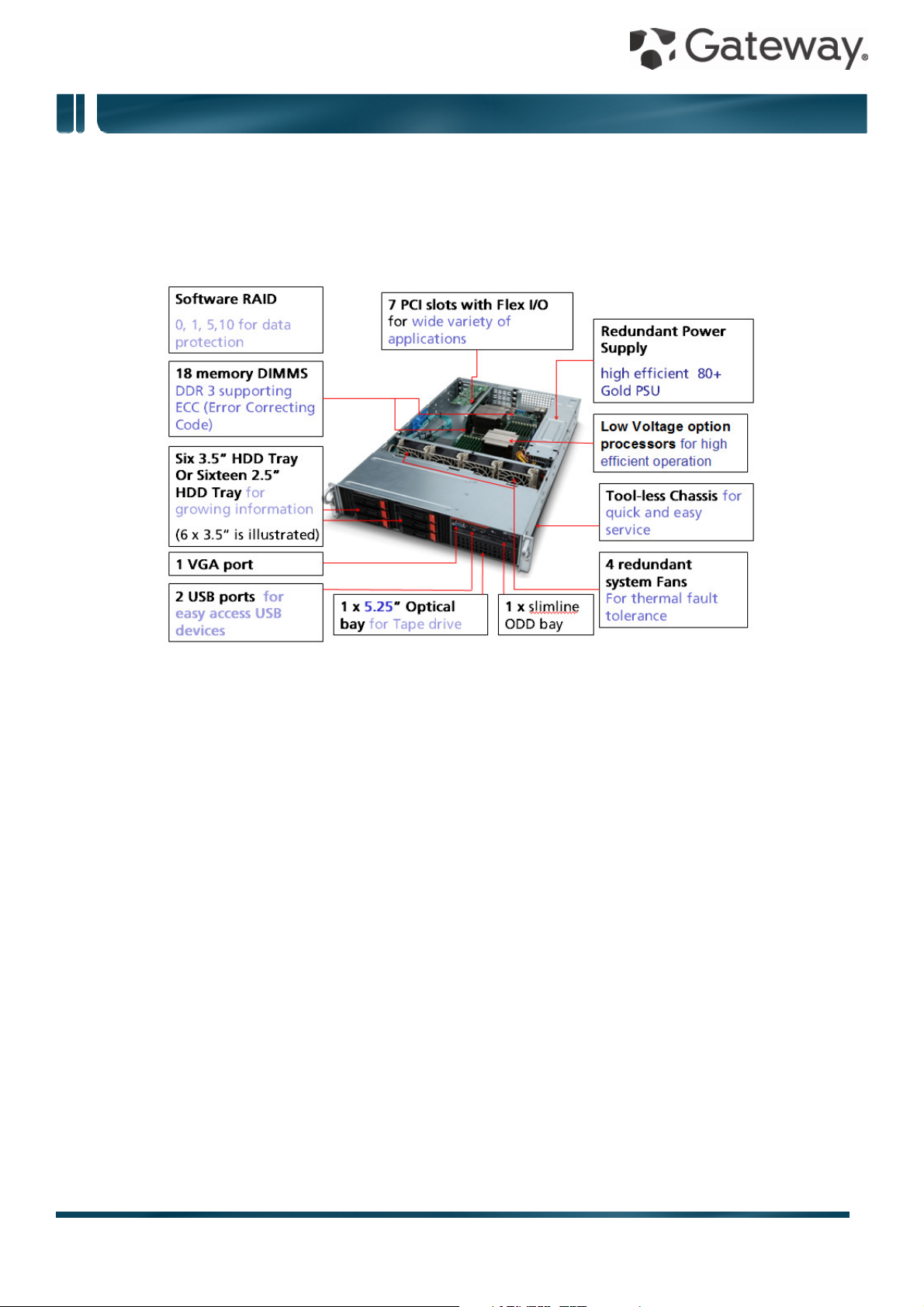
Internal view
1 2 x 720 W 80 PLUS® gold-level efficient easy-swap power supplies (1+1 redundant, hot-pluggable)
2 2 x Intel® Xeon® X5600 series processors
3 18 x DDR3 ECC registered / unbuffered DIMMs
4 3+1 redundant cooling fans
5 7 x PCIe expansion slots
6 1 x 5.25” media expansion bay
7 1 x slimline ODD bay
8 16 x 2.5” hot-swappable hard drive bays or
6 x 3.5” hot-swappable hard drive bays
Note: Availability may vary by region
1
Page 2
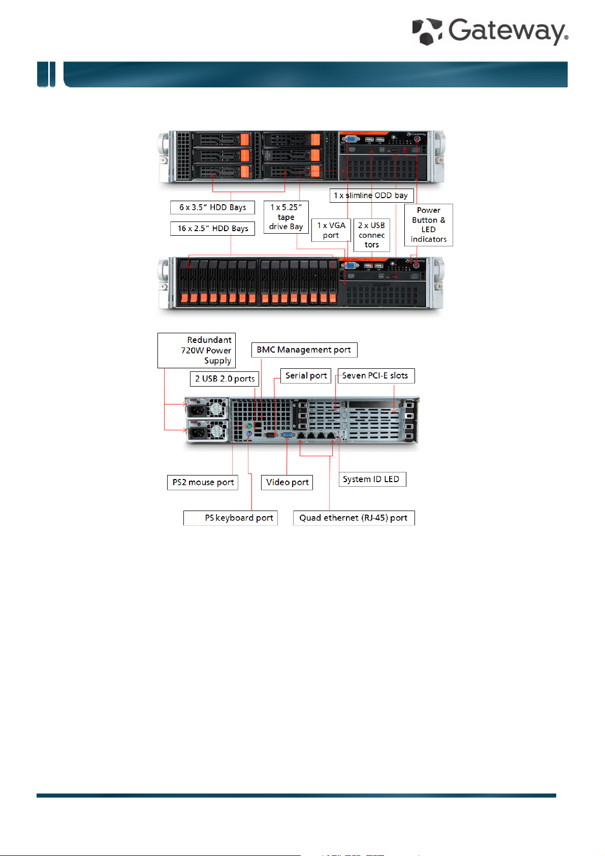
Front View
GR380 F1 specifications
Rear View
Front I/O
1 2 x USB ports
2 Video port
Note: Only one video port may be used at any given time
3 ID LED button
4 Network, hard drive and power status indicators
Rear I/O
1 PS2 mouse and keyboard ports
2 2 x USB ports
3 4 x Gigabit LAN port (RJ-45)
4 Video port
Note: Only one video port may be used at any given time
5 Serial port
6 System ID LED
7 Management port (RJ-45)
2
Page 3

What's New
GR380 F1 specifications
• New Intel® Xeon® 5600 Series processors
Intel Xeon X5675, X5672, E5649, E5645, E5607, E5606, E5603
• Hot-pluggable/redundant power supply with 80 PLUS® gold-level efficiency
• Smart Server Manager v1.1 with improved management functionality
Product Specifications
Processors and Chipset
• Up to two Intel® Xeon® 5500/5600 series processors
• Chipset: Intel® 5520
Memory
• Memory capacity:
Registered DIMM: 1, 2, 4, 8, 16 GB
Unbufferred DIMM: 1, 2, 4 GB
• Maximum capacity: up to 192 GB registered DIMMs when fully populated with 2 DIMMs per channel in
12 slots
• Maximum capacity: up to 48 GB unbuffered DIMMs when fully populated with 2 DIMMs per channel in
12 slots
Network Controllers
• Integrated dual-port Intel® 82576EB Gigabit Ethernet Controller (4 ports total)
Storage
• Hard disk form factor: 2.5” or 3.5”
• Type: SAS / SATA / SSD with hot-plug capability
• 3.5” Maximum capacity:
Up to 12 TB SATA HDD (2 TB 3.5" x 6 HDDs)
Up to 3.6 TB SAS (600 GB 3.5” x 6 HDDs)
• 2.5” Maximum capacity:
Up to 16 TB SATA HDD (1 TB 2.5" x 16 HDDs)
Up to 9.6 TB SAS (600 GB 2.5” x 16 HDDs)
Storage Controllers
• Integrated Intel® ICH10R Serial ATA host controller (six 3 Gb/s SATA ports) with software RAID 0, 1, 5,
10 support
• Optional PCIe 4-/8-/16-port SAS RAID card
Expansion slots
• One Gateway Flex I/O (PCIe® 2.0 x8) slot (left)
• Two full height PCIe® 2.0 x8 slots (with x4 link; left)
• One full height PCIe® 2.0 x16 slot (with x8 link left)
• Three low profile PCIe® 2.0 x8 slots (with x4 link; right)
Management
• Gateway Smart Server Manager
• System ID LED buttons, System Health LED
• Gateway Smart Console for server management and KVM over IP remote management
Deployment/Serviceability
3
Page 4

•
GR380 F1 specifications
Gateway Smart Setup
• BIOS Update Tool
• IPMI Firmware Update Tool
Operating Systems
• Windows Server® 2008
• Windows Server 2008 R2
• Windows Server 2003
• Red Hat Enterprise Linux 5.4
• SuSE Linux Enterprise Server 11
• VMware ESXi™ 4
• VMware ESX™ 4
Input/output interface
Front
• Two USB ports
• One VGA port
• One Power/off button
• LED indicators: Power, HDD activity, LAN port 1 through 4, ID, and System status
Rear
• PS2 keyboard port
• PS2 mouse port
• Two USB 2.0 ports
• BMC Management port
• Serial port
• Video port
• 4 x Gigabit port
• ID LED
Optical drive
• Slim-line SATA DVD Super multi
• 5.25” tape drive
Chassis/Form Factor
• 2U rack optimized
Power Supply
• 2 x 720 W 80 PLUS® gold-level efficient, easy-swap power supply (1+1 redundant, hot-pluggable)
Regulatory Compliant Standards
EMC
• FCC (Class A)
• CE (Class A)
• BSMI (Class A)
Safety
• UL/cUL
• CB
Nemko/GS
4
Page 5

GR380 F1 specifications
Environmental Specifications
Dimensions 438.4 mm (W) x 705 mm (D) x 88.1 mm (H) ( 17.3 x 27.8 x 3.5 inches)
Weight Maximum 39 kg (88.1 lbs)
Minimum (includes a single HDD, CPU and
RAM, and PSU)
System inlet
temperature
Relative
humidity
Acoustics Idle
LWAd 6.4 BA
LpAm 45.8 dBA
Operating
LWAd 7.2 BA
LpAm 53.6 dBA
Operating 10° - 35° C (50° - 95° F)
Non-operating -40° - 70° C (-40° - 158° F)
Operating 8 - 90 %
Non-operating 5 - 95 %
28.5 kg (62.8 lbs)
Power Rated Steady –state power 720 W
Maximum Peak Power 728 W
BTU rating 2456.64 BTU/hr at 100 - 240 VAC
5
Page 6

•
GR380 F1 specifications
Technical specifications
PCIe® specifications
The primary I/O bus for the main board is PCIe Gen2. The following table lists the characteristics of the
PCI-E bus segments. Details about each bus segment follow the table.
NOTE: The signaling bit rate of PCI Express is 2.5Gbit/s one direction per lane for Gen 1 and 5.0Gbit/s one
direction per lane for Gen 2.
Expansion
slot
PCIe x16 1 PCIe
PCIe x8 2 PCIe
PCIe x8 3 PCIe
Flex I/O 1 PCIe
NOTE:
Number Type Bus
width
x8 3.3V x16 Riser, left Full height
Gen2
x4 3.3V x8 Riser, left Full height
Gen2
x4 3.3V x8 Riser,
Gen2
x8 3.3V x8 Riser, left Full height
Gen2
1
Voltage Connector Location Length
low-profile
right
1. Indicates the number of physical electrical lanes running to a PCIe® connector.
2. Default bus assignment (in decimal). Inserting cards with PCI™ bridges may alter the actual bus
assignment number.
3. Slots are enumerated differently based on the operating system. Microsoft® operating systems
enumerate Device ID by bus starting from the lowest bus to the highest.
Onboard storage specifications
Item Description
Controller Intel® 82801JR (ICH10R) I/O Controller Hub
Simultaneous drive transfer channels 6 onboard SATA ports
Max throughput per channel 3 Gb/s
Data transfer method
• Non-RAID mode
• RAID mode
Drive type supported Serial ATA
RAID levels support
• RAID 0, 1, 10, 5 (Intel software RAID)
• RAID 0, 1, 10 (Adaptec software RAID)
NOTE: Intel software RAID only supports Windows OS
RAID function support
Supports multiple logical volumes
Setup through ROM based Array Configuration Utility
Installation scripting support
NOTE: This controller does not support LED functions
RAID OS support
Windows Server 2008
6
Page 7

•
®
GR380 F1 specifications
Windows Server 2008 R2
• Windows Server 2003
• Red Hat Enterprise Linux 5.4
• SuSE Linux Enterprise Server 11
Additional features
Onboard LAN specifications
Item Description
Controller 2 x Intel® 82576EB Gigabit Ethernet Controller
Network interface 10Base-T / 100Base-TX / 1000Base-T
Compatibility standards
Manageability
• NCQ (Native Command Queuing)
• AHCI (Advanced Host Controller Interface)
(4 ports total)
• IEEE 802.3 Ethernet interface for 10BASE-T
• IEEE 802.3ab Ethernet interface for 1000BASE-T,
• IEEE 802.3u Ethernet interface for 100BASE-TX
• NC-SI, SMBus
• PXE, iSCSI boot
Virtualization acceleration
Intel
Virtual Machine Device Queues (VMDq)
PCI-SIG SR-IOV implementation
I/O Acceleration Technology
Connector RJ-45
Supported cable type CAT 5e wire
Memory specifications and population
Item Description
Supported memory types
• Registered DDR3 1066 / 1333 MHz
• Unbuffered DDR3 1066 / 1333 MHz
NOTE: Gateway does not qualify mixed memory configurations of
memory type, capacity or make.
Population Gateway’s validated memory populations are listed below.
NOTE: Support for 8 / 16 GB DIMMs may vary by regional
availability.
Single processor configuration guide
NOTE: Quad Rank DIMMs and Unbuffered DIMMs can only use a maximum of 6 slots
DIMM # DIMM1C DIMM
1B
1 X
2 X X
DIMM
1A
DIMM
2C
DIMM
2B
DIMM2A DIMM3C DIMM3B DIMM3A
7
Page 8

GR380 F1 specifications
3 X X X
4 X X X X
6 X X X X X X
9 X X X X X X X X X
Dual processor configuration guide
NOTE: Quad Rank DIMMs and Unbuffered DIMMs can only use a maximum of 6 slots per CPU (12 slots
total)
DIMM
# 1C 1B 1A 2C 2B 2A 3C 3B 3A 1C 1B 1A 2C 2B 2A 3C 3B 3A
2 X X
3 X X X
4 X X X X
6 X X X X X X
8 X X X X X X X X
9 X X X X X X X X X
12 X X X X X X X X X X X X
CPU 1 CPU 2
18 X X X X X X X X X X X X X X X X X X
3 DIMM per channel configuration is only available for single/dual rank RDIMM. UDIMM and Quad rank
RDIMM can only support 2 DIMM per channel.
* support depends on 8GB/16GB DIMM available
Mirroring mode:
• For mirroring mode, the memory contains a primary image and a copy of the primary image. Therefore,
the effective size of memory is reduced by at least one-half.
• Channel 3 is no function and can’t be populated in this mode.
• Follow the population rules described in independent mode.
• Mirroring mode needs the channel 1 & channel 2 with identical DIMM. DIMM slot populations within a
channel do not have to be identical but the same DIMM slot location across channel 1 and channel 2
must be the same. DIMM1A and DIMM2A should be the same type, size and manufacturer. DIMM1B
and DIMM2B memory should be the same type, size and manufacturer. DIMM1C and DIMM2C
memory should be the same type, size and manufacturer.
• Same rule is applied to the CPU2.
• 3 DIMM per channel configuration is only available for single/dual rank RDIMM.
• Please refer to the User Guide for complete population for both single and dual processor
configurations.
Lockstep mode:
• In Lockstep Channel Mode, each memory access is a 128-bit data access that spans Channel 1 and
Channel 2. This is done to support SDDC for DRAM devices with 8-bit wide data ports. The same
8
Page 9

GR380 F1 specifications
address is used on both channels such that an address error on any channel is detectable by bad
ECC. Lockstep Channel mode is the only RAS mode that supports x8 SDDC.
• Channel 3 is no function and can’t be populated in this mode.
• Follow the population rules described in independent mode.
• Lockstep mode needs the channel 1 & channel 2 with identical DIMM. DIMM slot populations within a
channel do not have to be identical but the same DIMM slot location across channel 1 and channel 2
must be the same. DIMM1A and DIMM2A should be the same type, size and manufacturer. DIMM1B
and DIMM2B memory should be the same type, size and manufacturer. DIMM1C and DIMM2C
memory should be the same type, size and manufacturer.
• Same rule is applied to the CPU2.
• 3 DIMM per channel configuration is only available for single/dual rank RDIMM.
• Please refer to the User Guide for complete population for both single and dual processor
configurations.
.
Sparing mode:
• In this mode, if system detects degrading memory and system still not crash, the data in failed channel
will be copied to spare channel. Failed channel is then isolated and spare channel becomes active. But if
any uncorrectable error happens before the isolation, it will still cause the system stop normal operation.
• Channel 3 is the spare channel. Therefore, the effective size will be reduced by one-third.
• Follow the population rules described in independent mode.
• Sparing mode need all three channels with identical DIMMs. 1A, 2A and 3A should be the same type,
size and manufacturer. 1B, 2B and 3B memory should be the same type, size and manufacturer. 1C, 2C
and 3C memory should be the same type, size and manufacturer. Same rule is applied to CPU2.
• Memory sparing mode is only supported by Intel Xeon 5600 series processor. Intel Xeon 5500 series
processor does NOT support the memory sparing mode.
• 3 DIMM per channel configuration is only available for single/dual rank RDIMM.
• Please refer to the User Guide for complete population for both single and dual processor
configurations.
Memory Identification
Generally, there are some memory information printed on the label of DIMM, but different vendor may have
different format. For example:
4GB 2Rx4 PC3-10600R xx xx xxx
1. Density
1GB, 2GB, 4GB, 8GB, 16GB
2. Rank
1R = Single Rank
2R = Dual Rank
4R = Quad Rank
Note: if any quad rank DIMM is used, maximum only 2 DIMM per channel can be supported
9
Page 10

GR380 F1 specifications
3. Bit Organization
This platform supports x4 and x8
Note: It’s not recommend to mix DIMM with different bit organization in one system
4. Speed
PC3 – 6400 => DDR3- 800
PC3 – 8500 => DDR3- 1066
PC3 – 10600 => DDR3- 1333
10
Page 11

GR380 F1 specifications
Power specifications
720W Power Supply
Operational Input
Voltage Range
(Vrms)
Frequency
Range (Nominal)
(Hz)
Nominal Input
Voltage (Vrms)
Max. Rated
Output Wattage
Nominal Input
Current (A rms)
Max. Rated Input
Wattage Rating
(Watts)
Max. Rated VA
(Volt-Amp)
100 to 240
60/50
846.0 836.4 790.4 774.0 822.8 805.0 789.6
837.54 828.03 774.59 758.52 806.34 788.9 773.81
100 120 208 200 220 230 240
720 720 720 720 720 720 720
8.46 6.97 3.80 3.87 3.74 3.5 3.29
Efficiency (%) at
Max. Rated
Output Wattage
Power Factor 0.99 0.99 0.98 0.98 0.98 0.98 0.98
Leakage Current
(mA)
Max. Inrush
Current (A peak)
Max. Inrush
Current Duration
(mS)
Max. British
Thermal Unit
Rating (BTU/hr)
88.12 89.49 90.95 90.74 91.51 91.92 92.27
0.17 0.19 0.29 0.31 0.35 0.37 0.41
17.24 19.41 18.52 16.88 16.48 20.47 22.54
4.62 4.58 4.61 4.62 4.64 4.63 4.64
2456.64 2456.64 2456.64 2456.64 2456.64 2456.64 2456.64
11
Page 12

GR380 F1 specifications
Gateway server software utilities
Smart Setup 2.0
Smart Console
Smart Server
Manager v1.1
Easy deployment via the latest version of Gateway’s Smart Setup. Smart Setup is
available both in box as a driver packed installation DVD or a downloadable file to be
put into a USB 2.0 device, and eases the deployment of Gateway servers for any
certified OS. Through its unique interface, users may select to have all the correct
drivers be pre-deployed for the OS of their choosing, as well as setup hardware RAID
devices, BMC settings (where available), and even clone the pre-settings to a
bootable USB device to ease mass server deployments.
Web-based management utility to simplify system management with embedded
iBMC, system monitoring and alerting, event handling, remote power control and
KVM-over-IP. Smart Console is OS independent and offers virtual media through
floppy, ODD, and removable disk.
Offering 24-7 monitoring for system health and performance.
Delivers proactive event management features including system event logging,
event handling from e-mail and SNMP Trap (PET) alerting.
Monitors onboard hardware, operating systems and virtual machines
Allows remote control from KVM and Power control
Satisfies management in web-based UI, role-based administration, and automated
management scripts.
12
Page 13

GR380 F1 specifications
Available options
Processors (up to 2)
Intel® Xeon® processor (Six Core)
X5675 (12 MB L3 cache, 3.06 GHz, DDR3-1333 MHz, 95W)
X5670 (12 MB L3 cache, 2.93 GHz, DDR3-1333 MHz, 95 W)
X5660 (12 MB L3 cache, 2.80 GHz, DDR3-1333 MHz, 95 W)
X5650 (12 MB L3 cache, 2.66 GHz, DDR3-1333 MHz, 95 W)
L5640 (12 MB L3 cache, 2.26 GHz, DDR3-1333 MHz, 60 W)
E5649 (12 MB L3 cache, 2.53 GHz, DDR3-1333 MHz, 80 W)
E5645 (12 MB L3 cache, 2.40 GHz, DDR3-1333 MHz, 80W)
Intel® Xeon® processor (Quad Core)
X5672 (12 MB L3 cache, 3.20 GHz, DDR3-1333 MHz, 95W)
X5667 (12 MB L3 cache, 3.06 GHz, DDR3-1333 MHz, 95 W)
X5570 (8 MB L3 cache, 2.93 GHz, DDR3-1333 MHz, 95 W)
X5560 (8 MB L3 cache, 2.80 GHz, DDR3-1333 MHz, 95 W)
X5550 (8 MB L3 cache, 2.66 GHz, DDR3-1333 MHz, 95 W)
E5640 (12 MB L3 cache, 2.66 GHz, DDR3-1066 MHz, 80 W)
E5630 (12 MB L3 cache, 2.53 GHz, DDR3-1066 MHz, 80 W)
E5620 (12 MB L3 cache, 2.40 GHz, DDR3-1066 MHz, 80 W)
L5630 (12 MB L3 cache, 2.13 GHz, DDR3-1066 MHz, 40 W)
L5609 (12 MB L3 cache, 1.86 GHz, DDR3-1066 MHz, 40 W)
E5607 (8 MB L3 cache, 2.26 GHz, DDR3-1066 MHz, 80 W)
E5606 (8 MB L3 cache, 2.13 GHz, DDR3-1066 MHz, 80 W)
E5603 (4 MB L3 cache, 1.60 GHz, DDR3-1066 MHz, 80 W)
E5540 (8 MB L3 cache, 2.53 GHz, DDR3-1066 MHz, 80 W)
E5530 (8 MB L3 cache, 2.40 GHz, DDR3-1066 MHz, 80 W)
E5520 (8 MB L3 cache, 2.26 GHz, DDR3-1066 MHz, 80 W)
E5506 (4 MB L3 cache, 2.13 GHz, DDR3-800 MHz, 80 W)
E5504 (4 MB L3 cache, 2 GHz, DDR3-800 MHz, 80 W)
L5520 (8 MB L3 cache, 2.26 GHz, DDR3-1066 MHz, 60 W)
L5506 (4 MB L3 cache, 2.13 GHz, DDR3-800 MHz, 60 W)
Intel® Xeon® processor (Dual Core)
E5502 (4 MB L3 cache, 1.86 GHz, DDR3-800 MHz, 80 W)
13
Page 14

GR380 F1 specifications
Memory
Memory type Registered / Unbuffered DDR3 ECC memory
Capacities 1 / 2 / 4 / 8 / 16 GB DIMMs
DIMM number 18
Max memory 192 GB (48 GB unbuffered)
Hard drives
Type Interface, bandwidth Capacities (RPM)
Enterprise SATA, 2.5” 3 Gb/s 150 GB (10K)
160 GB (7.2K)
300 GB (10K)
500 GB (7.2K)
1 TB (7.2K)
Enterprise SATA, 2.5” 6 Gb/s 250 GB (7.2K)
500 GB (7.2K)
1 TB (7.2K)
Enterprise SATA, 3.5” 3 Gb/s 250 GB (7.2K)
500 GB (7.2K)
750 GB (7.2K)
1 TB (7.2K)
2 TB (7.2K)
Enterprise SAS, 2.5”
NOTE: SAS drives require an
add-on RAID card
Enterprise SAS, 3.5”
NOTE: SAS drives require an
add-on RAID card
6 Gb/s 73 GB (15K)
146 GB (15K)
300 GB (10K)
450 GB (10K)
600 GB (10K)
6 Gb/s 146 GB (15K)
300 GB (15K)
450 GB (15K)
600 GB (15K)
Optical drives
DVD-ROM
SuperMulti (DVD ± RW)
14
Page 15

GR380 F1 specifications
RAID cards
Model Port number RAID support
LSI® MegaRAID SAS 9240-4i 4 internal ports 0, 1, 5, 10
LSI® MegaRAID SAS 9260-8i* 8 internal ports 0, 1, 5, 6, 10, 50, 60
Flex I/O, LSI® SAS 2108* 8 internal ports 0, 1, 5, 6, 10, 50, 60
LSI® MegaRAID SAS 9260-16i* 16 internal ports 0, 1, 5, 6, 10, 50, 60
*Battery Backup Unit BBU07 available
RAID HBA for Tape Drive
Note: LTO tape drives require an add on card for external or internal connectivity
Model Port number RAID support
LSI® SAS3442E-R 4 internal / 4 external ports 0, 1, 10
Ethernet network cards
Model Port number Bandwidth
Intel® Gigabit CT2 desktop
adapter
Supermicro AOC-SG-i2 server
adapter
Supermicro AOC-SG-i4 server
adapter
Supermicro AOC-STGN-i2S
server adapter (DA2)*
Intel® X520-SR1 server adapter* 1 10 Gbps
Intel® X520-SR2 server adapter* 2 10 Gbps
Intel® X520-LR1 server adapter* 1 10 Gbps
*Note: Intel’s 10GbE cards vary in terms or their connecter type. The X520-DA2 is a copper connector for
lengths up to 7M, while the X520-SR1/2 is an optical connection for cables up to 550M. The X520-LR1 is
for even longer cable lengths up to 10kM.
Fibre Channel HBAs
Model Port number Bandwidth
Qlogic® QLE2460 1 4 Gb/s
1 10/100/1000 Mbps
4 10/100/1000 Mbps
4 10/100/1000 Mbps
2 10 Gbps
Qlogic® QLE2462 2 4 Gb/s
Qlogic® QLE2560 1 8 Gb/s
Qlogic® QLE2562 2 8 Gb/s
Tape Backup Unit (TBU)
15
Page 16

GR380 F1 specifications
Model Tape capacity Form factor
LTO Ultrium-3, 3Gb/s SAS 400/800 GB External 1U rack
LTO-4, 3Gb/s SAS 400/800 GB External 1U rack
DAT72 SATA/USB TBU 36 GB
72 GB
DAT160 USB TBU 160 GB Internal 5.25” half-height
TPM module
TPM module with STMicro chip
Internal 5.25” half-height
16
Page 17

GR380 F1 specifications
Service and support
Gateway Servers offer a comprehensive service suite to take care of daily IT needs. Users can select the 3year standard warranty or choose extended warranties and services.
In a continuing effort to improve the quality of our products, information in this document is subject to
change without notice. Images shown are only representations of some of the configurations available for
this model. Availability may vary depending on region.
© 2010. All rights reserved.
Microsoft and Windows are registered trademarks of Microsoft Corporation. Intel, the Intel logo, Xeon and
Xeon Inside are trademarks of Intel® Corporation.
NOTE: Extension warranty services may vary by country. Please contact Gateway authorized resellers for
more information.
17
 Loading...