


PART NO.:
Gateway GT115
Service Guide
PRINTED IN TAIWAN

Preface
1. This Service Guide provides you with all technical information relating to the BASIC CONFIGURATION
decided for Gateway's "global" product offering. To better fit local market requirements and enhance
product competitiveness, your regional office MA Y have decided to extend the functionality of a machine
(e.g. add-on card, modem, or extra memory capability). These LOCALIZED FEATURES will NOT be
covered in this generic service guide. In such cases, please contact your regional offices or the
responsible personnel/channel to provide you with further technical details.
2. Please note WHEN ORDERING FRU PARTS, that you should check the most up-to-date information
available on your regional web or channel. If, for whatever reason, a part number change is made, it will not
be noted in the printed Service Guide. For GATEWAY-AUTHORIZED SERVICE PROVIDERS, your
Gateway office may have a DIFFERENT part number code to those given in the FRU list of this printed
Service Guide. You MUST use the list provided by your regional Gateway office to order FRU parts for
repair and service of customer machines.
Revision History
Please refer to the table below for the updates made on Gateway GT115 service guide.
Date Chapter Updates
Copyright
Copyright © 2009 by Gateway Incorporated. All rights reserved. No part of this publication may be
reproduced, transmitted, transcribed, stored in a retrieval system, or translated into any language or computer
language, in any form or by any means, electronic, mechanical, magnetic, optical, chemical, manual or otherwise,
without
the prior written permission of Gateway Incorporated.
Disclaimer
The information in this guide is subject to change without notice.
Gateway Incorporated makes no representations or warranties, either expressed or implied, with respect to
the contents hereof and specifically disclaims any warrantie s of merchantability or fitness for any particular
purpose. Any Gateway Incorporated software described in this manual is sold or licensed "as is". Should
the
programs prove defective following their purchase, the buyer (and not Gateway Incorporated, its distributor, or
its dealer) assumes the entire cost of all necessary servicing, repair, and any incidental or consequential
damages resulting from any defect in the software.
Gateway is a registered trademark of Gateway
Corporation. Intel is a registered trademark of Intel
Corporation.
Pentium and Pentium II/III are trademarks of Intel Corporation.
Other brand and product names are trademarks and/or registered trademarks of their respective holders.
I

Conventions
The following conventions are used in this man ual
:
Screen messages
NOTE Gives bits and pieces of additional
WARNING Alerts you to any damage that might
CAUTION Gives precautionary measures to
IMPORTANT Reminds you to do specific actions
Denotes actual messages that appear
on screen.
information related to the current
topic.
result from doing or not doing specific
actions.
avoid possible hardware or software
problems.
relevant to the accomplishment of
procedures.
II

Safety, Care and Regulatory Information
Before installing a server, be sure that you understand the following warnings and cautions.
WARNING: To reduce the risk of electric shock or damage to the equipment:
Do not disable the power cord grounding plug. The grounding plug is an important safety feature.
Plug the power cord into a grounded (earthed) electrical outlet that is easily accessible at all times.
Unplug the power cord from the power supply to disconnect power to the equipment.
Do not route the power cord where it can be walked on or pinched by items placed against it. Pay particular
attention to the plug, electrical outlet, and the point where the cord extends from the server.
WARNING:To reduce the risk of personal injury from hot surfaces, allow the drives and the internal
system components to cool before touching them.
CAUTION: Do not operate the server for long periods with the access panel open or removed.
Operating the server in this manner results in improper airflow and improper cooling that can lead to thermal
damage.
Preventing electrostatic discharge
To prevent damaging the system, be aware of the precautions you need to follow when setting up the system
or handling parts. A discharge of static electricity from a finger or other conductor may damage system boards
or other static-sensitive devices. This type of damage may reduce the life expectancy of the device. To
prevent electrostatic damage:
Avoid hand contact by transporting and storing products in static-safe containers.
Keep electrostatic-sensitive parts in their containers until they arrive at static-free workstations.
Place parts on a grounded surface before removing them from their containers.
Avoid touching pins, leads, or circuitry.
Always be properly grounded when touching a static-sensitive co mponent or assembly.
Server warnings and cautions
Before installing a server, be sure that you understand the following warnings and cautions.
WARNING: To reduce the risk of electric shock or damage to the equipment:
1. Do not disable the power cord grounding plug. The grounding plug is an important safety feature.
2. Plug the power cord into a grounded (earthed) electrical outlet that is easily accessible at all times.
3. Unplug the power cord from the power supply to disconnect po wer to the equipmen t.
4. Do not route the power cord where it can be walked on or pinched by items placed against it. Pay
particular attention to the plug, electrical outlet, and the point where the c ord e xtends from the server.
WARNING: To reduce the risk of personal injury from hot surfaces, allow the drives and the internal
system components to cool before touching them.
CAUTION: Do not operate the server for long periods with the access panel open or removed. Operating the
server in this manner results in improper airflow and improper cooling that can lead to thermal damage.
III

Table of Contents
PREFACE I
REVISION HISTORY I
COPYRIGHT I
DISCLAIMER I
CONVENTIONS II
SAFETY, CARE AND REGULATORY INFORMATION III
PREVENTING ELECTROSTATIC DISCHARGE III
SERVER WARNINGS AND CAUTIONS III
TABLE OF CONTENTS 1
MECHANICAL COMPONENTS 4
SYSTEM FRU LIST 6
SYSTEM COMPONENTS 9
SYSTEM SPECIFICATIONS 10
Hardware specification 10
Environmental specification 12
Mechanical specification 13
Power supply specification 14
APPEARANCE OF SYSTEM 16
Front view 16
Rear view 17
Internal Component 18
Switch and LED Indicators Introduction 19
1

Front Panel LED Description 19
Hard Disk Drive Sequence & LED Description 19
LAN Port LED Description 19
System Block Diagram 21
MOTHERBOARD PLACEMENT AND JUMPER SETTING 22
Motherboard Component 22
Connector Icon Description 23
Motherboard Jumper Setting 24
INSTALLING/REMOVING SYSTEM HARDWARE 25
Chassis Cover Removal and Installation 26
Removing the side cover 26
CPU Installation / Removal 27
Cooling Fan Installation / Removal 28
Memory Installation / Removal 29
PCI Expansion Card Installation / Removal 30
Install the expansion card 30
Hard Disk Drive Installation / Removal 31
Power supply installation / Removal 32
Install a hot-swap power supply module 32
CABLE ROUTING 33
Cable Routing image 33
BIOS SETUP 34
Main Menu 36
Advanced Menu 37
Processor Configuration 38
Memory Configuration 40
SATA Controller Configuration 41
PCI Configuration 42
USB Configuration 43
Legacy Device Configuration 44
Console Redirection 45
Power Configuration 47
Hardware Monitor 48
2

Security Menu 49
Setting a System Password 50
Changing a System Password 50
Removing a System Password 50
Server Menu 51
System Information 52
Event Log Configuration 53
Boot Option Menu 54
Boot Manager Menu 56
Exit Menu 57
TROUBLESHOOTING 58
Error Symptoms List 58
BIOS BEEP CODES 61
BIOS Beep Codes Table 61
PEI Beep Codes 61
DXE Beep Codes 61
BIOS Recovery Instruction 61
BIOS POST ERROR MESSAGES LIST 64
BIOS POST error message list 64
PEI Phase 64
DXE Phase 65
UNDETERMINED PROBLEMS 67
3
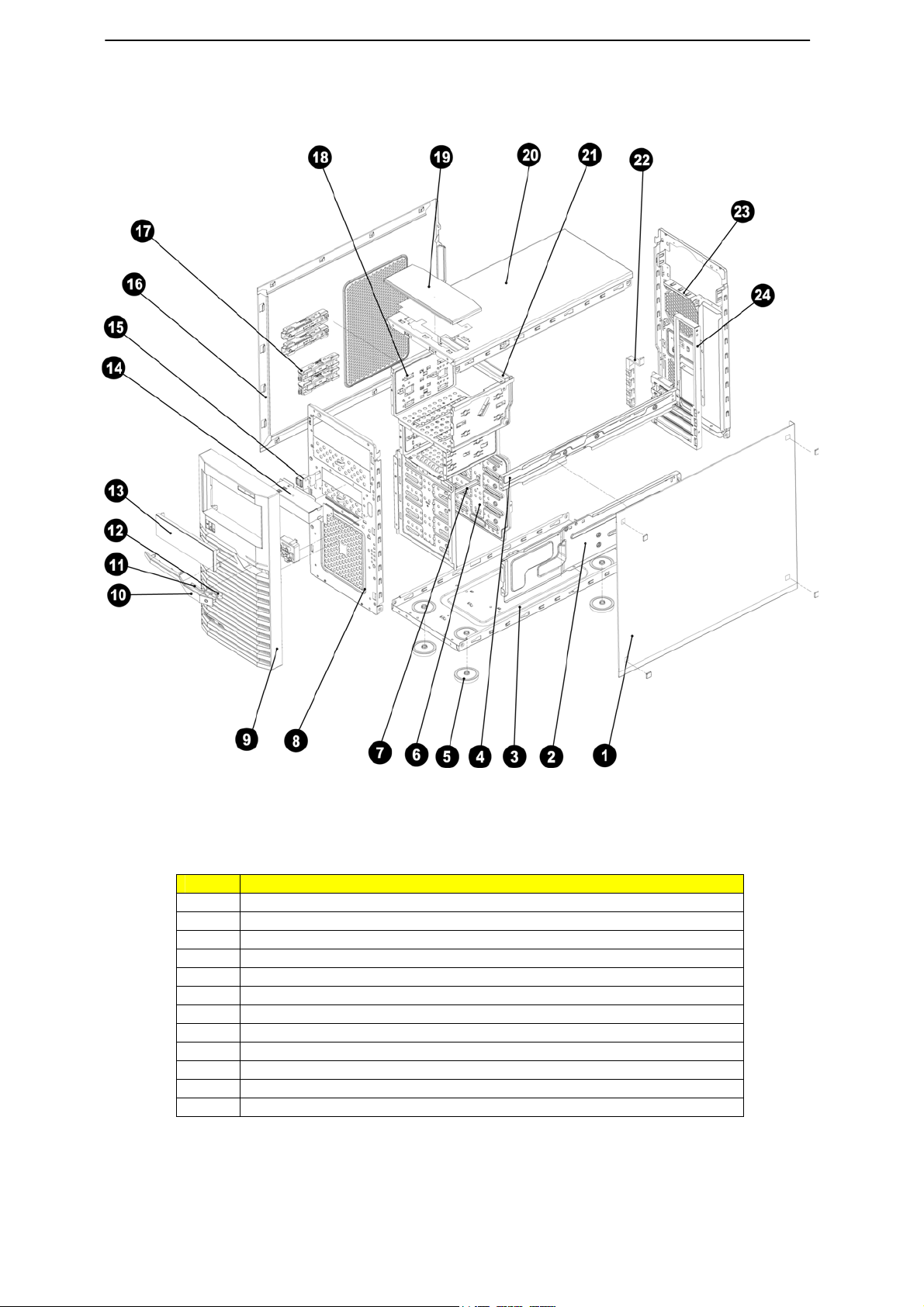
Mechanical Components
Item Description
1 Right side cover
2 System support retainer
3 System bottom plate
4 System support retainer
5 System plastic stands
6 Hard drive cage
7 Hard drive bracket
8 Front door plate
9 Front bezel
10 Power button
11 Bezel lens
12 Power lens
4

13 Optical drive cage
14 USB bracket
15 USB bracket
16 Left side cover
17 Hard drive slider
18 Hard drive cage
19 Top cover
20 System top cover
21 CD-ROM bracket patch
22 PCI retainer
23 Back cover
24 Rear window
5
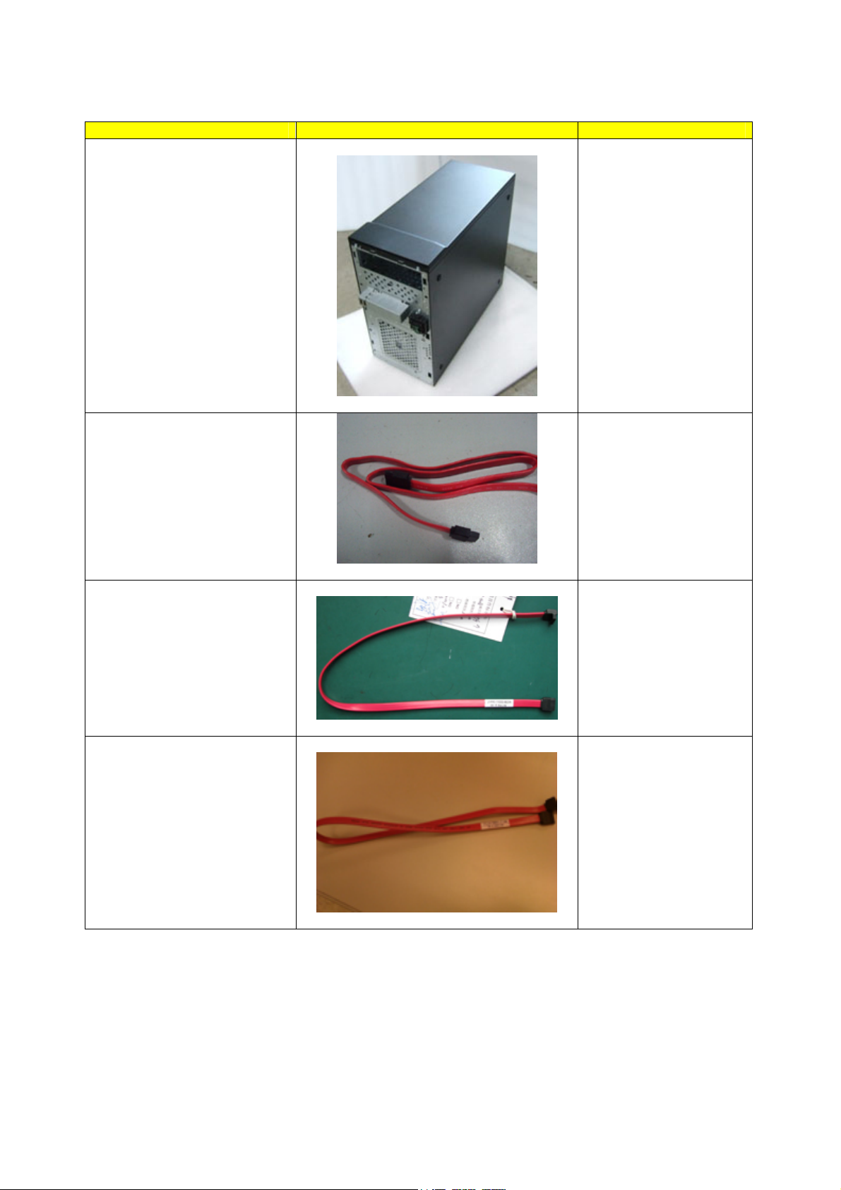
System FRU List
Item Photo Part number
Chassis
HS.31600.004
SATA ODD CABLE 7 PINS,
500MM
SATA HDD CABLE 7 PINS,
500MM
SAS HDD CABLE
CA.R4300.001
CA.R4300.002
CA.31400.030
6
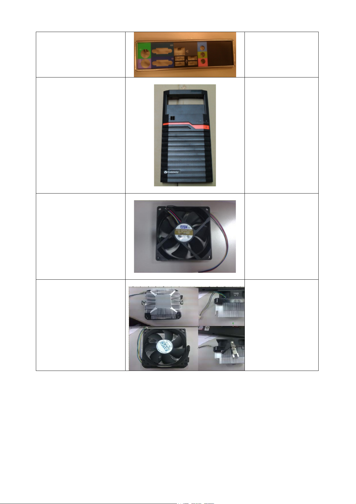
Back I/O SHIELD
33.R7F0L.001
FRONT BEZEL ASSEMBLY
SYSTEM FAN
TZ.R4300.001
HI.R4300.001
SYSTEM FAN
SINK
HI.30900.024
7

Main Board
MB.R7F0A.001
FSP FSP450-60EP 450W
POWER SUPPLY
Mylar
PY.45008.001
47.R7F0L.001
8
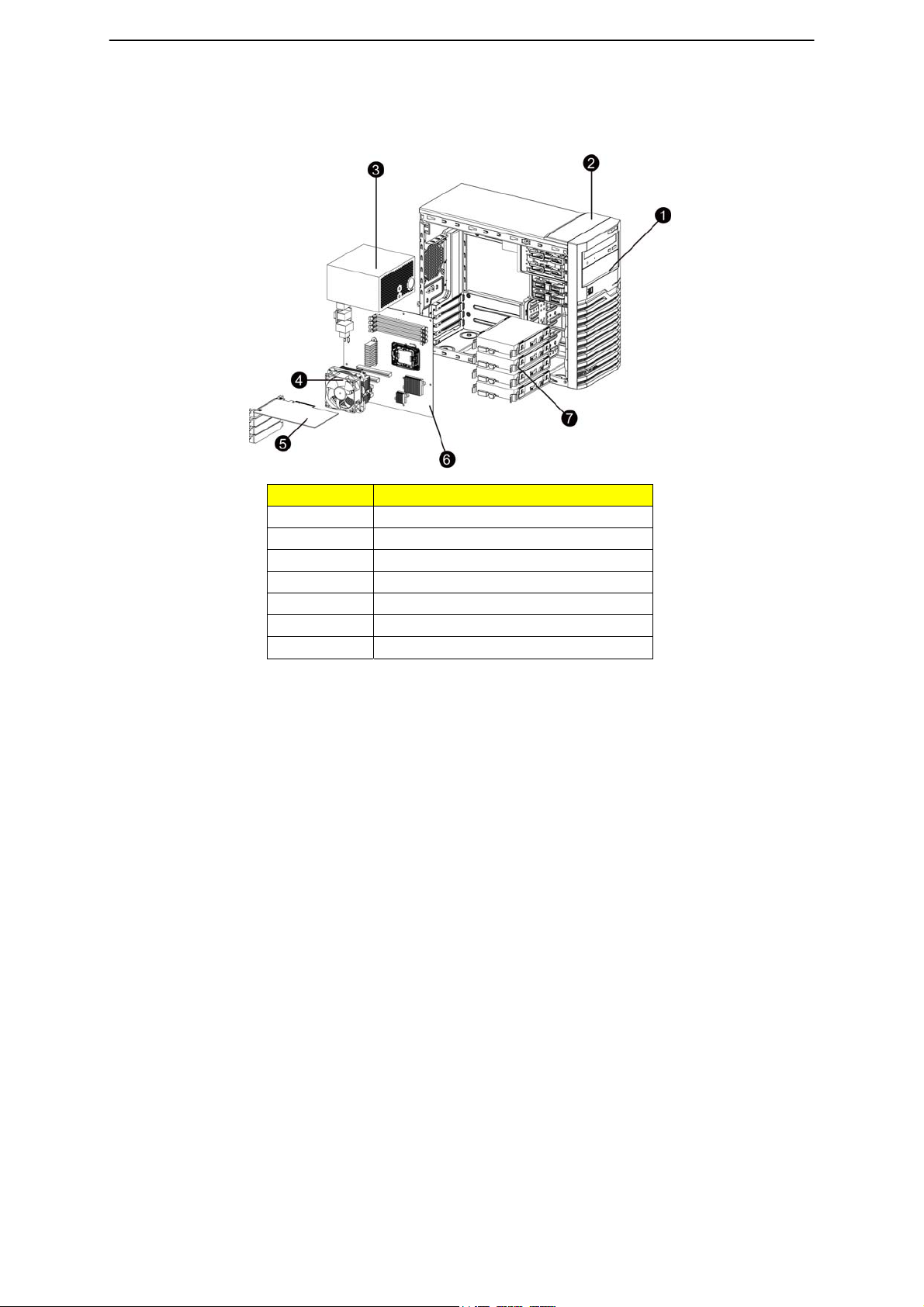
System components
Item Description
1 Front Bezel door
2 Top cover
3 Power supply cage
4 Cooling fan cage
5 PCI card
6 Main board
7 Hard drive blank
9

System Specifications
Hardware specification
System unit
Item Description
Processor socket AMD socket C32
Memory Technolo gy – Socket C32 interfaces to DDR3 SDRAM
DIMMs.
Processor support
HyperTransport™ Technology.
Thermal Monitoring and Control – The Socket C32 processor uses
Advanced Platform Management Link.
Core logic chipsets
LAN controller
Memory controller
Storage controller
VGA controller
I/O subsystem
Memory
I/O ports
AMD SR5670 – North bridge
AMD SP5100 – South bridge
INTEL 82574L
Integrated in AMD socket C32 processor.
Software RAID – Integrated in AMD SP5100.
XGI Volari – Z9S with 64 MB VRAM.
PCI-E 1 – PCI Express x16 line with x16 slot.
PCI-E 2 – PCI Express x8 line with x8 slot.
PCI-E 3 – PCI Express x4 line with x4 slot.
PCI-E 4 – PCI Express x1 line with x4 slot.
Four DDR3 (1066/1333 MHz ) slots.
Support maximum 64GB at 800MHz.
Front panel – Two USB ports.
Rear panel – PS/2 keyboard port, PS/2 mouse port, COM port, Four
USB ports, Video Port, Audio jack (Option), LAN port.
Internal – Two USB ports for tape device, USB port, I2C Connector,
TPM, Six SATA ports.
Status LED indicators
Thermal solution
Front panel – Power, Hard drive, System Status and LAN activity.
Rear panel – Activity and link status for the LAN ports.
One system fan.
One processor heat sink fan.
One front panel fan.
10

Memory
Item Description
Number of DIMM slots
Maximum memory
capacity
Memory modes Single DIMM, non-interleaving (DIMM A1)
Memory controller Integrated in the AMD socket C32 processor
DIMM specifications
Size
Speed
Type
Four
8 GB (2 GB in each of the four DIMM slots)
Two DIMMs, interleaving (DIMM A1 and DIMM B1)
Four DIMMs, full memory configuration
512 MB, 1 GB, 2GB, and 4 GB
1066/1333 MHz
DDR3 Unbuffered ECC DIMM
Processor
General processor specifications
Item Description
Manufacturing
technology
Thermal design power 95W
45nm
65nm
Socket type C32
11

Environmental specification
Item Description
Temperature range
Operating
Non-operating
Humidity (non-condensing)
Operating
Non-operating
Acoustic noise
Full Configuration
Light Configuration
* All temperature ratings shown are for sea level. An altitude derating of 1¢XC per 300 m (1.8¢XF per 1,000 ft)
to 3048 m (10,000 ft) is applicable. No direct sunlight allowed.
** Storage maximum humidity of 95% is based on a maximum temperature of 45¢XC (113¢XF). Altitude
maximum for storage corresponds to a pressure minimum of 70 KPa.
5–35°C (41–95°F)
-20–60C (-4–140°F)
30–80% RH
20–90% RH
Sound pressure level in idle mode on bystander
position <38 dBA
Sound pressure level in full loading on bystander
position <45 dBA
Sound pressure level in idel mode on bystander
position <35 dBA
Sound pressure level in full loading on bystander
position <40 dBA
12

Mechanical specification
Item Description
System board platform uATX (Micro Advanced Technology Extended)
System board dimensions
Length
Width
System Dimensions
Height
Depth
Width
Server weight (maximum
configuration, approximate)
Basic configuration (excluding the
keyboard and mouse)
Fully loaded configuration
(including the keyboard, mouse,
and kits)
304.8mm
243.84mm
358mm
180mm
450mm
8KG
12.2KG
13

Power supply specification
GT115 supports 300-watts and 450W po wer supply modules. You have the option to install
a 300-watts power supply module or 450W power supply module.
Note: If you need to install three hard disk drives, please use 300W power supply (with
three connectors). If you need to install four hard disk drives, please use 450W power
supply (with four connectors).
Item Description
Model
Type
Dimensions
Height
Depth
Width
Weight (approximate) 1.28 kg (2.82 lb)
Input requirements
Rated input voltage
Normal line voltage
Line frequency
Rated input current Load 7A at 100–127 VAC, 3.5A at 220-240 VAC
Inrush current
Power supply output power
Rated steady state power
Maximum peak power
Operating conditions
Temperature
Humidity (non-condensing)
Item Description
Model
Type
Dimensions
Height
FSP300-60EP(1)
300W
86 mm (3.38 in.)
140 mm (5.5 in.)
150 mm (5.9 in.)
100–127 VAC, 220–240 VAC
115 VAC, 230 VAC
47–63 Hz
No damage
300W
300W
5–50 C (41–122°F)
5–95% at +55 C
FSP450-60EP
450W
86 mm (3.38 in.)
14

Depth
Width
Weight (approximate) 1.43 kg (3.1 lb)
Input requirements
Rated input voltage
Normal line voltage
Line frequency
Rated input current Load 8A at 100–127 VAC, 4A at 220-240 VAC
Inrush current
Power supply output power
Rated steady state power
Maximum peak power
Operating conditions
Temperature
Humidity (non-condensing)
140 mm (5.5 in.)
150 mm (5.9 in.)
100–127 VAC, 220–240 VAC
115 VAC, 230 VAC
47–63 Hz
No damage
450W
450W
5–50 C (41–122°F)
5–95% at +55 C
15
Appearance of System
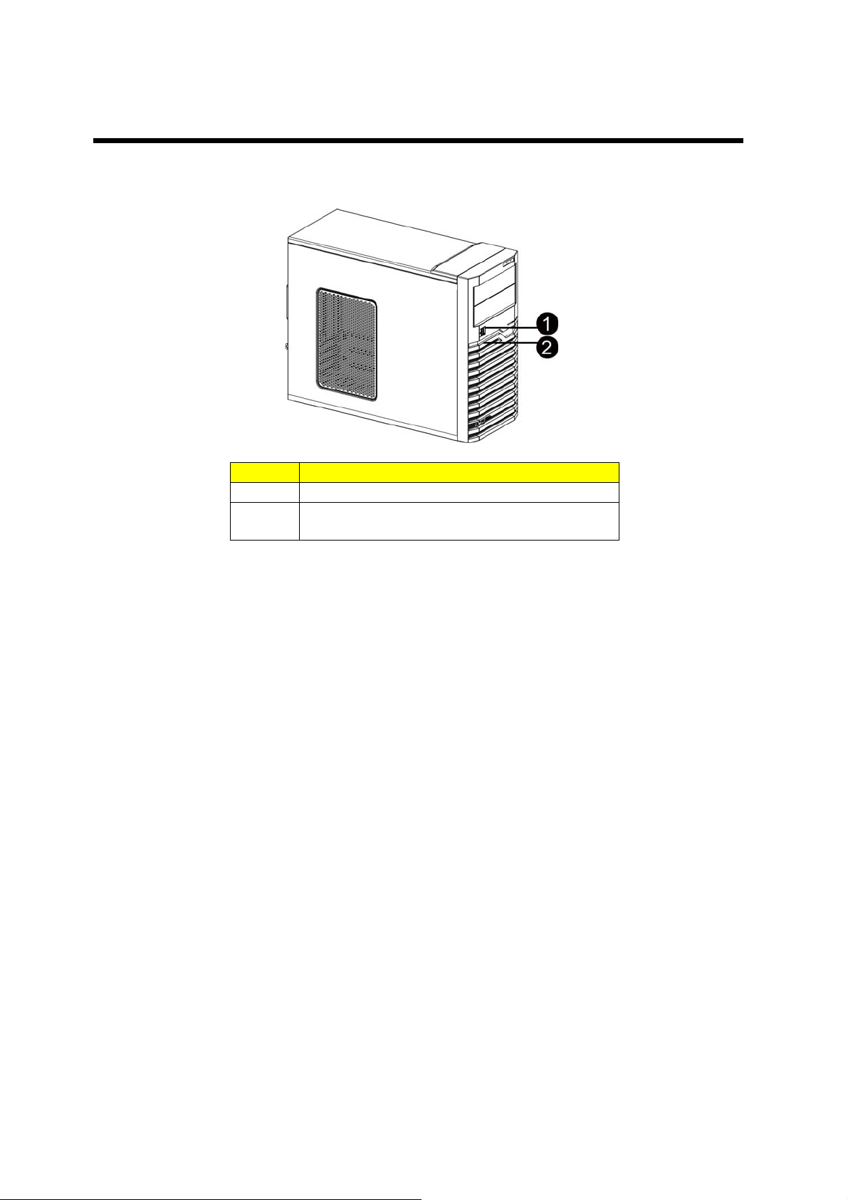
Front view
Item Component
1 USB connectors
2 LED indicator panel
16
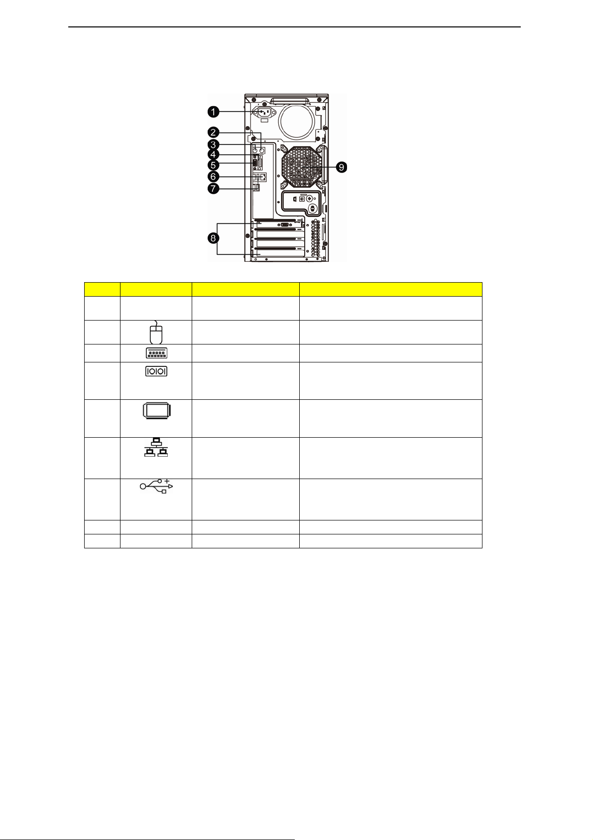
Rear view
Item
1
2
3
4
Icon
Component
Power supply module cord
socket
PS/2 mouse por
PS/2 keyboard
Serial port
t
Connect the system power cord here.
Connects to a PS/2 mouse.
Connects to a PS/2 keyboard.
Connects to serial devices.
Description
5
Monitor port
Connects to monitors
.
6
Gigabit LAN ports 1/2
Connects to an Internet or intranet network
.
7
USB 2.0 ports
Connects to USB devices.
8
9
PCI slot covers
System fan
Protects to an Internet or intranet network.
Regulates the system airflow
.
17
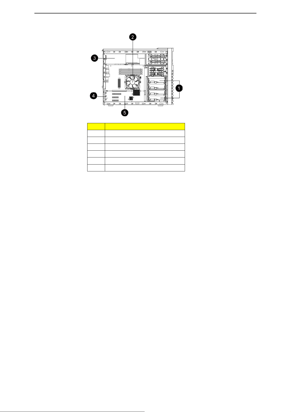
Internal Component
Item LED indicator
1 Release sliders for the HDD cages.
2 Cooing fan assemblies.
3 Power module bay
3 Cooing fan assemblies
4 PCI slot lock levers
5 Mainboard
18
Switch and LED Indicators Introduction
This section discusses the different LED indicators located on the :
Front panel
Hot-plug HDD carrier
LAN port
Knowing what each LED indicator signifies can aid in problem diagnosis and troubleshooting.
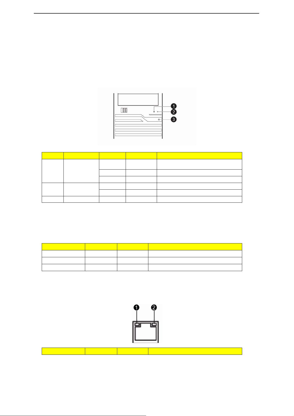
Front Panel LED Description
Number LED Color Status Description
1 LAN Activity
3 Power Green Solid On System is powered on.
Green Solid on Link between system and network or no
access
Green Blink Network access
-- Off Disconnect/Idle
Green Blink HDD access 2 HDD Activity
-- Off No HDD access
Hard Disk Drive Sequence & LED Description
A drive activity LED indicator is mounted on the hot-plug HDD carrier. The table below lists the possible drive
states.
Status Green Amber Description
HDD access Blinking -- Ongoing hot-plug HDD activity
HDD failure -- On Hot-plug HDD failure
HDD rebuild Flashing green/amber HDD is rebuilding data
LAN Port LED Description
Indicator Color Status Description
19

A
1. Network speed
(top)
2. Network
connection
(bottom)
mber On GbE link network access
Green On 100 Mbps link network access
Off 10 Mbps link network access
Green On Active network link
Green Blinking Ongoing network data activity
Off Off-line network
20
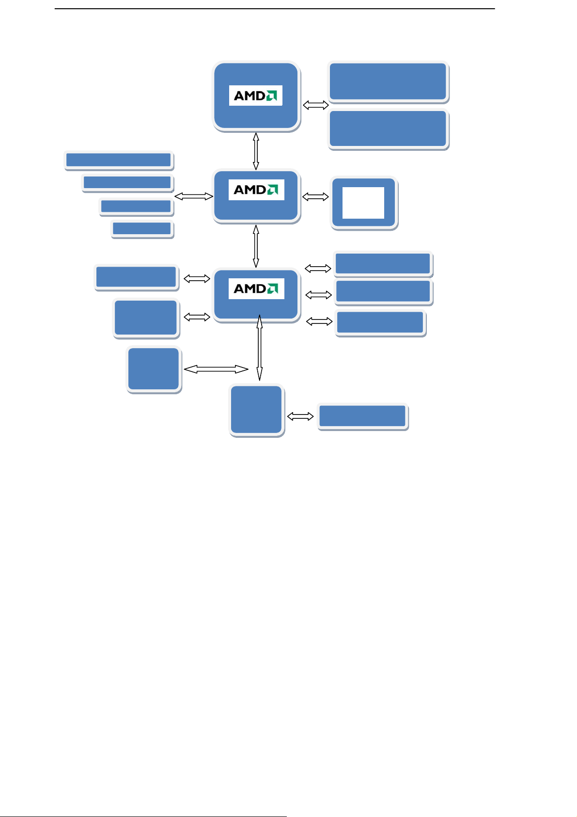
System Block Diagram
Channel A
2 DDR3 UDIMMs /
RDIMMs
PCI-E x 16 Slot1
PCI-E x 8 Slot2
PCI-E x 4 Slot3
PCI-E x 1Slot4
USB Port x 9
XGI-Z9S
(64MB DDR2)
Flash SPI
BIOS
Socket
NB: SR5670
SB: SP5100
Channel B
2 DDR3 UDIMMs /
RDIMMs
Intel®
82574L
SATA Port x 6
Audio (Option)
TPM (Option)
SIO
IT8720
Series Port x2
21

Motherboard Placement and Jumper Setting
Motherboard Component
This section provides general information on changing jumper settings as well as specific jumper
configuration for individual boards in the system.
22

Connector Icon Description
Item Code Description Item Code Description
1 PS/2 ports Connect to mouse and
keyboard.
3 VGA port Connect to monitors. 4 RJ45/USB ports The RJ45 port connects to an
5 USB ports Connect to USB devices. 6 ATX1 12-pin ATX power connector
7 DIMM_2B DIMM slot 8 DIMM_2A DIMM slot
9 DIMM_1B DIMM slot 10 DIMM_1A DIMM slot
11 CPU_FAN1 CPU fan cable connector 12 CPU Processor socket
13 SATA4 SATA cable connector 14 SATA6 SATA cable connector
15 SATA5 SATA cable connector 16 SATA3 SATA cable connector
17 SATA1 SATA cable connector 18 SATA2 SATA cable connector
19 CASE_OPEN2 Case open intrusion 20 F_Panel Front panel connector
21 CLR_CMOS1 Clear CMOS jumper 22 F_USB2 Front USB2 cable connector
23 F_USB1 Front USB1 cable connector 24 BAT1 CMOS battery
25 TPM1 TPM connector 26 USB_A1 USB type A connector
27 SMBUS_CONN SMBus connector 28 FRONT_FAN1 System fan cable connector
29 COM2 Serial port connector 30 PCI-E_4 PCI-E x4 slot (x1 signal)
31 PCI-E_3 PCI-E x4 slot (x4 signal) 32 PCI-E_2 PCI-E x8 slot (x8 signal)
33 PCI-E_1 PCI-E x16 slot (x16 signal) 34 REAR_FAN1 System fan cable connector
35 ATX_CPU1 8-pin ATX power connector
2 Serial port Connect to serial devices.
internet or intranet network.
The USB ports connect to
USB devices.
23

Motherboard Jumper Setting
Item Description
1 Clear CMOS jumper (CLR_CMOS1)
1-2 Close: Normal operation. (Default)
2-3 Close: Clear CMOS data.
24

Installing/Removing system Hardware
This chapter contains step-by-step procedures on how to disassemble the server system for maintenance
and troubleshooting.
To disassemble the Gateway GT115 Server, please pay attention to each section’s instruction and tools
needed.
NOTE: The screws for the different components vary in size. During the disassembly process, group the
screws with the corresponding components to avoid mismatch when putting back the components.
25

Chassis Cover Removal and Installation
Removing the side cover
1. Remove the two screws located on the rear edge of the side panel.
2. Press the side panel release button and slide the side panel toward the rear of the chassis to disengage it.
Removing the tower foot
1. Release the bezel door retention tabs from the chassis interior.
2. Pull the bezel away from the chassis.
26

CPU Installation / Removal
The mainboard supports one C32 processor socket with Dual/Four/Six-Core AMD Opteron™ 4100 series. You
have the option to upgrade the default processor.
Observe the following guidelines when replac ing a processor.
•
Before removing a processor, make sure to back up all important system files.
•
Handle the processor and the HSF assembly carefully. Damage to either may prevent the system
from functioning properly.
NOTE: A long-nosed screwdriver is needed to remove/install the HSF assembly.
1. Release then lift up the load lever.
2. Open the retention plate to expose the socket body.
3. Insert the CPU with the correct orientation.
4.
Close the retention plate and close the lever to the locked position.
27

Cooling Fan Installation / Removal
1. Disconnect the processor cooling fan cable from mainboard.
2. Use a long-nosed screwdriver to loosen the four cooling fan mounting pins.
3. Lift the cooling fan away from the mainboard.
4. Lay down the cooling fan in an upright position - with the thermal patch facing upward. Do not let the
thermal patch touch the work surface.
28

Memory Installation / Removal
The motherboard supports DDR3 memory modules, whereby BIOS will automatically detect memory
capacity and specifications. Memory modules are designed so that they can be inserted only in one
direction. The memory capacity used can differ with each slot.
Installation step:
1. Insert the DIMM memory module vertically into the DIMM slot, and push it down.
2. Close the plastic clip at both edges of the DIMM slots to lock the DIMM module.
NOTE! DIMM must be populated in order starting from DIMMA1/B1 socket. For dual-chann el
operation, DIMMs must be installed in matched pairs.
3. Reverse the installation steps when you wish to remove the DIMM module.
Memory Suggest Population Table:
29

PCI Expansion Card Installation / Removal
Gateway GT115 has four bus slots with of three separate bus segments:
Install the expansion card
•
PCI-E_1 -- PCI Express x16 slots
•
PCI-E_2 -- PCI Express x8 slot
•
PCI-E_3 -- PCI Express x4 slot
•
PCI-E_4 -- PCI Express x4 slot with x1 signal
1. Press the release latch of the slot cover opposite the selected expansion slot.
2. Pull out the slot cover and store it for reassembly later.
NOTE: Do not discard the slot cover. If the expansion card is removed in the future, the slot cover must be
reinstalled to maintain proper system cooling.
NOTE: Remove the expansion card from its protective packaging, handling it by the edges.
3. Insert the card into the selected slot. Make sure that the card is properly seated.
4. Press the release latch to secure the card in place.
5. Connect the necessary cables to the expansion card as required.
30

Hard Disk Drive Installation / Removal
Below is the instruction of HDD installation and removal SOP.
1. Open the side cover.
2. Press the release button and pull the blank out of the drive bay.
3. Slide hard disk into blank.
4. Make sure the HDD is seated securely in the HDD blank.
5. Connect the necessary power cable. To connect power cable. Firstly, remove the HDD carrier.
Note!! Make sure that the drive is properly inserted before pushing the handle back until it clicks into
Place.
31
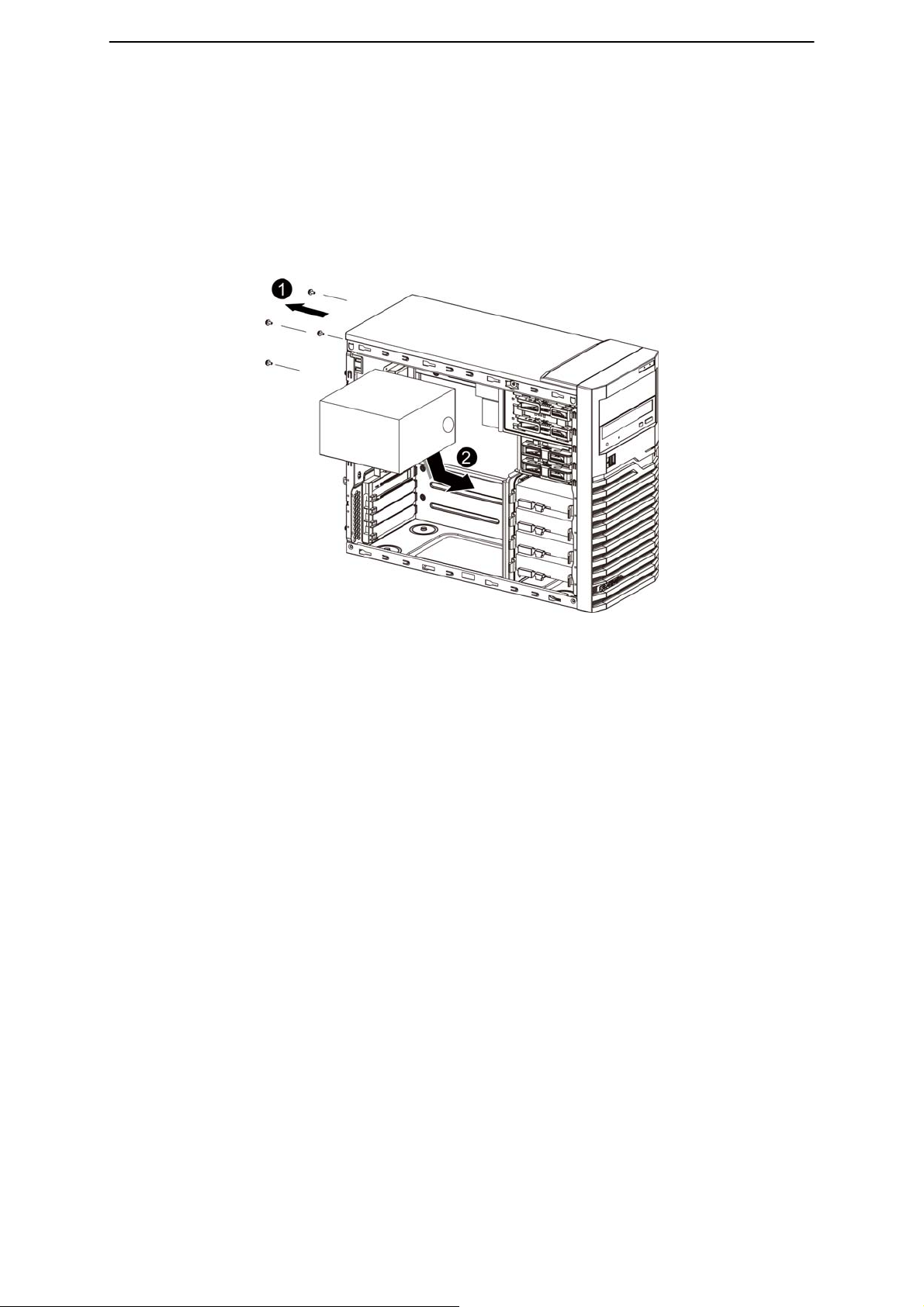
Power supply installation / Removal
The GT115 supports 300 watts and 450 watts power supply modules. The system ships out with only one
power supply module installed.
Install a hot-swap power supply module
1. Remove the four securing screws from the back of system.
2. Slide toward and lift to remove the power supply module from the system.
3. To install a new power supply module, please reverse the installation step 1and 2.
4. After replacing a power supply module, connect the necessary cables.
32
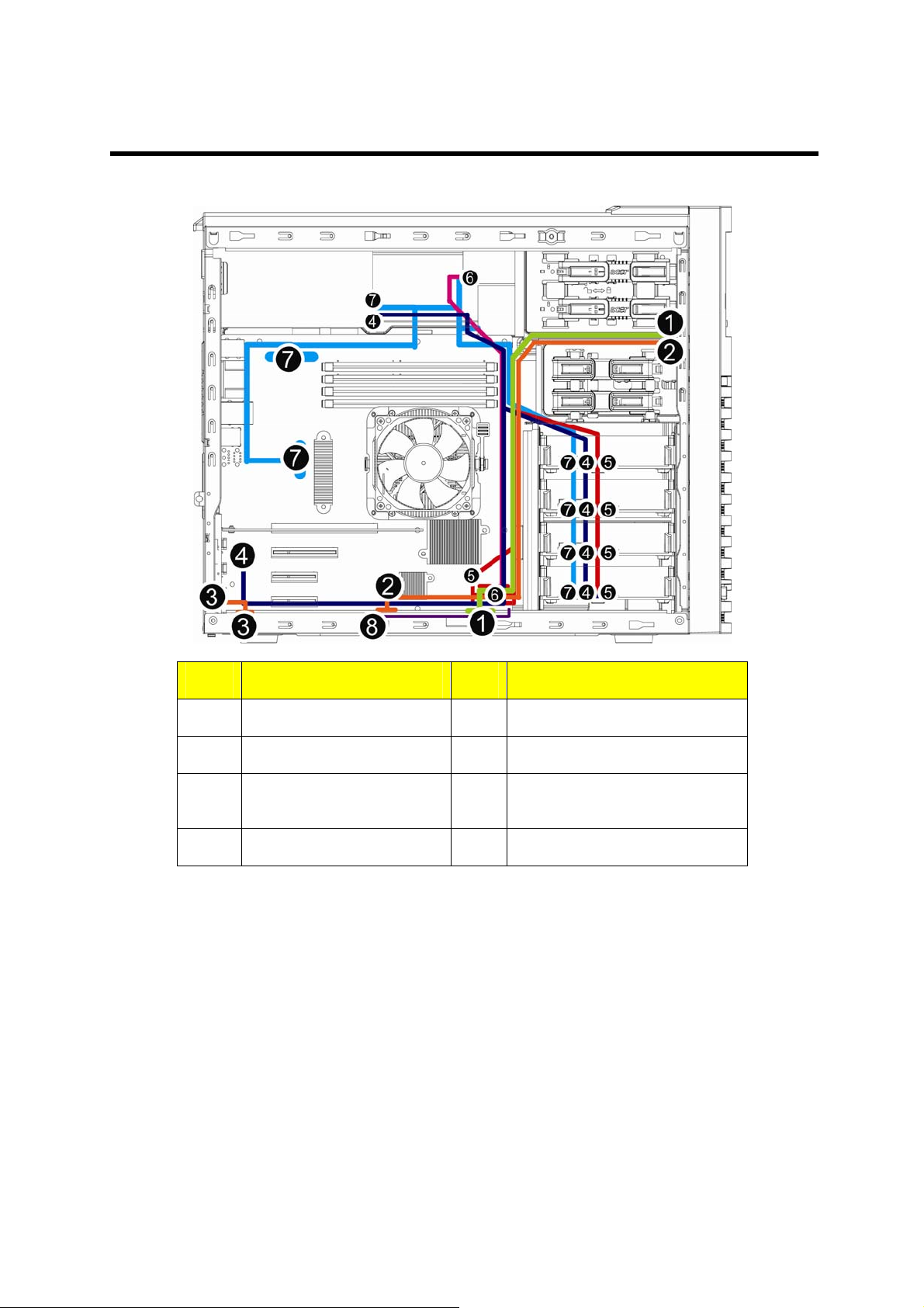
Cable Routing
Cable Routing image
Item Suggest Cable Item Suggest Cable
1 Front switch cable 2 Front USB cable
3 Serial port cable 4 Mini SAS cable
5 SATA cable (onboard SATA
to HDD)
7 Power cable 8 Case open intrusion
6 SATA cable (onboard SATA to
ODD)
33

BIOS Setup
System BIOS
BIOS setup is a hardware configuration program built into the system’s Basic Input/Output System (BIOS).
Since most systems are already properly configured and optimized, there is no need to run this utility. You will
need to run this utility under the following conditions.
NOTE: If you repeatedly receive Run Setup messages, the battery may be bad. In this case, the system
BIOS setup loads the configuration values in a battery-backed nonvolatile memory called CMOS RAM. This
memory area is not part of the system RAM which allows configuration data to be retained when power is
turned off.
Before you run the Phoenix BIOS Setup Utility, make sure that you have saved all open files. The system
reboots immediately after you close the Setup.
NOTE: Phoenix BIOS Setup Utility will be simply referred to as “Setup” or “Setup utility” in this guide.
NOTE: The screenshots used in this guide display default system values. These values may not be the same
•
When changing the system configuration settings
•
When redefining the communication ports to prevent any conflicts
•
When modifying the power management configuration
•
When changing the password or making other changes to the security setup
•
When a configuration error is detected by the system and you are prompted (“Run Setup”
message) to make changes to the BIOS setup
cannot retain configuration values in CMOS. Ask qualified technician for assistance.
those found in your system.
34

Entering BIOS Setup
1. Turn on the server and the monitor.
If the server is already turned on, close all open applications, then restart the server.
2. During POST, press F2
If you fail to press F2 before POST is completed, you will need to restart the server. The Setup Main menu
will be displayed showing the Setup’s menu bar. Use the left and right arrow keys to move between
selections on the menu bar.
BIOS Setup Primary Menus
The tabs on the Setup menu bar correspond to the six primary BIOS Setup menu, namely:
•
Main
•
Advanced
•
Security
•
Server Management
•
Boot Option
•
Boot Manager
•
Exit
In the descriptive table following each of the menu screenshots, settings in boldface are the default and
suggested settings.
BIOS Setup Navigation Keys
Use the following keys to move around the Setup utility.
•
Left and Right arrow keys - Move between selections on the menu bar.
•
Up and Down arrow keys - Move the cursor to the field you want.
•
PgUp and PgDn keys - Move the cursor to the previous and next page of a multiple page menu.
•
Home - Move the cursor to the first page of a multiple page menu.
•
End - Move the cursor the last page of a multiple page menu.
•
+ and - keys - Select a value for the currently selected field (only if it is user-configuration). Press
these keys repeatedly to display each possible, or the Enter key to choose from a pop-up menu.
NOTE: Grayed-out fields are not user-configurable.
•
Enter key - Display a submenu screen.
NOTE: Availability of submenu screen is indicated by a (>)
•
Esc - If you press this key:
q
On one of the primary menu screens, the Exit menu displ ays.
q
On a submenu screen, the previous screen displays.
q
When you are making selections from a pop-up menu, closes the pop-up without making a
selection.
•
F1 - Display the BIOS setup General Help panel.
•
F9 - Press to load default system values.
•
F10 - Save changes made the Setup and close the utility.
35

Main Menu
Parameter Description
BIOS Version Version number of the BIOS setup utility.
BIOS Build Date Date when the BIOS setup utility was created.
Processor
CPU Type CPU Core Frequency CPU
Count
System Time Set the system time following the hour-minute- second format.
Technical specifications for the installed processor.
System Date Set the date following the weekday-month-day- year format.
36

Advanced Menu
The Advanced menu di splay submenu options for configuring the function of various hardware
components. Select a submenu item, then press Enter to access the related submenu screen.
37

Processor Configuration
A
A
r
Parameter Description Option
MD PowerNow This feature will increase the system battery life, while
delivering performance on demand. It also allows the
processor to dissipate less heat under normal operating
conditions, providing a cooler and quieter-running
system.
Enabled
Disabled
MT C1E Enable this feature will let your system utilize the AMD
specific ACPI states to save power consumption.
Core Leveling Mode Select the core level mode in the system
SVM Select whether to enable the AMD virtualization
function. VT allows a single platform to run multiple
operating systems in independent partitions.
BIST Error Halt With this feature enabled, if any BIST errors are
detected, the POST will stop, display errors, and wait fo
user to press F1 to continue POST.
Socket 0 Displays the type of installed processor information.
Quad Core Running Displays the Quad-Core running speed.
CPU Speed The processor speed is the speed at which a
microprocessor executes instructions. Clock speeds are
expressed in megahertz (MHz), with
1 MHz being equal to 1 million cycles per second. The
faster the clock, the more instructions the CPU can
execute per second.
Enabled
Disabled
utomatic mode
One core per processor
Two cores per processor
Three cores per processor
Enabled
Disabled
Enabled
Disabled
Max Speed The Max speed is the speed indicates how fast the data
bits travels in the system bus.
Intended Speed The Intended speed is the speed indicates the expected
speed that the data bits travels in the system bus.
38

Microcode Patch Level Processor Microcode Patch Level.
A
A
CPUID Processor ID number.
CPU Stepping Processor stepping information.
Processor L1 Instruction Cache Processor first-level instruction cache size detected
during POST.
n Instruction: to speed up executable instruction fetch.
Processor L1 Data Cache Processor first-level data cache size detected
during POST.
Data Cache: to speed up data fetch and store.
Processor L2 Cache Processor second-level cache size detected
during POST.
Total L3 Cache per Socket Processor third-level cache size detected
during POST.
39

Memory Configuration
A
Parameter Description Option
vailable Memory T ot al size of system memory detected during POST
On-line Spare DIMM Enable this feature will reserve one rank of one
logical DIMM to be used as spare rank. This rank
will be used when any other rank no longer
functions properly.
Channel interleaving This feature provides compe nsating the relatively
slow speed of DRAM. The CPU can access
alternative sections immediately without waiting for
memory to be cached. Multiple memory banks take
turns supplying data.
Chip Select interleave Enabled
Memory Retest Select whether to delete the historical memory data
log. System memory will be retested on the next
boot-up.
DIMM Group #1A/1B/2A/2B
Status
The size of memory installed on each of the DDR3
slots.
Enabled
Disabled
Enabled
Disabled
Disabled
Yes
No
40

SATA Controller Configuration
r
A
A
Parameter Description Option
Onboard SATA Controll When enabled, the SATA controller will
function normally.
Enabled
Disabled
OnChip SATA Type Select the on chip SATA type.
IDE: When set to IDE, the SATA controller
disables its RAID and AHCI functions and
runs in the IDE emulation mode. This is not
allowed to access RAID setup utility.
RAID: When set to RAID, the SATA controlle
enables both its RAID and AHCI functions.
You will be allows access the RAID setup
utility at boot time.
CHI: When set to AHCI, the SATA controller
enables its AHCI functionality. Then the RAID
function is disabled and cannot be access
the RAID setup utility at boot time.
SATA Port 0/1/2/3/4/5 Displ ays the installed HDD devices.
IDE
RAID
CHI
41

PCI Configuration
Parameter Description Option
PCI Express Slot 1/2/3/4 When enabled, This setting will initialize the
device expansion ROM for the related PCI-E
slot.
Enabled
Disabled
Onboard Graphics Cont When enabled, the graphic controller will
function normally.
Primary Video Device Select the primary video device that that the
BIOS will use for output.
Onboard LAN Controller When enabled, the system will enable the
onboard LAN devices.
Onboard LAN I/O ROM Select whether to enable the selected
onboard LAN device. When enabled, device
expansion ROM will be initialized.
PCI ROM Priority In case of multiple Option ROMs (Legacy
and EFI Compatible) specifies what PCI
option ROM to launch.
Enabled
Disabled
Onboard Video
PCIe slot Video
Enabled
Disabled
Enabled
Disabled
Legacy ROM
EFI Compatible
42

USB Configuration
Parameter Description Option
Detected USB Devices Displays the information of installed
USB devices in the system.
USB Controller When enabled, the USB controller
will function normally.
Legacy USB Support Enables or disables support for
legacy USB devices.
Port 60/64 Emulation Enable I/O port 60h/64h emulation
support. This should be enabled for
the complete USB Keyboard Legacy
support for non-USB aware OS.
Device Reset Timeout Define USB Mass Storage Device
Start Unit command timeout.
Enabled
Disabled
Enabled
Disabled
Enabled
Disabled
10 sec
20sec
30 sec
40sec
43

Legacy Device Configuration
Parameter Description Option
Serial Port 1/2 When enabled allows you to
configure the serial port settings.
When set to Disabled, displays no
configuration for the serial port.
Device Setting
Change Settings Change Serial Port 1/2 device
Displays Serial Port 1/2 device
setting information
settings.
When set to Auto allows the server’s
BIOS or OS to select a
configuration.
Enabled
Disabled
Auto
IO=3F8; IRQ=4
IO=3F8h; IRQ=3,4,5,6,7,10,11,12
IO=2F8h; IRQ=3,4,5,6,7,10,11,12
IO=3E8h; IRQ=3,4,5,6,7,10,11,12
IO=2E8h; IRQ=3,4,5,6,7,10,11,12
44
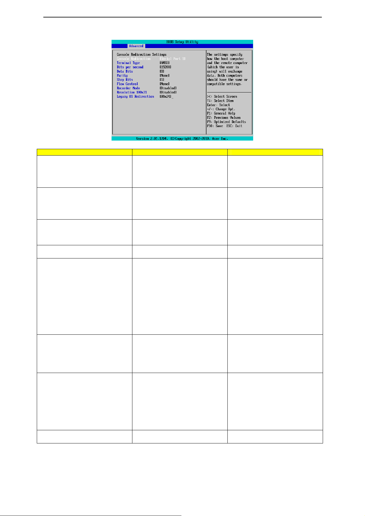
Console Redirection
Parameter Description Option
Console Redirection Select whether to enable console
redirection. Console redirection
enables users to manage the
system from a remote location.
Terminal Type
Bits per second Select the baud rate for console
Data Bits Sele ct the Data Bits. 7
Parity A parity bit can be sent with the data
Stop Bits Stop bits indicate the end of a serial
Flow Control Flow control can prevent data loss
Recorder Mode When this mode enabled, only text
Select a terminal type to be used for
console redirection.
redirection.
bits to detect some transmission
errors.
Even: parity bi is 0 if the num of 1's
in the data bits is even.
Odd: parity bit is0if num of 1's the
data bits is odd.
Mark: parity bit is always 1.
Space: Parity bit is always 0.
Mark and Space Parity do not allow
for error detection.
data packet. (A start bit indicates the
beginning).
The standard setting is 1 stop bit.
Communication with slow devices
may require more than 1 stop bit.
from buffer overflow. When sending
data, if the receiving buffers are full,
a 'stop' signal can be sent to stop
the data flow. Once the buffers are
empty, a 'start' signal can be sent to
re-start the flow. Hardware flow
control uses two wires to send
start/stop signals.
will be send. This is to capture
45
Serial Port 1
Serial Port 2
Disabled
VT100
VT100+
ANSI
VT-UTF8
9600
19200
57600
115200
8
None
Even
Odd
Mark
Space
1
2
None
Hardware RTS/CTS
Enabled
Disabled

Terminal data.
Resolution 100x31 Enables or disables extended
terminal resolution.
Legacy OS Redirection On Legacy OS, the number of Rows
and Columns supported redirection.
Enabled
Disabled
80x24
80X25
46
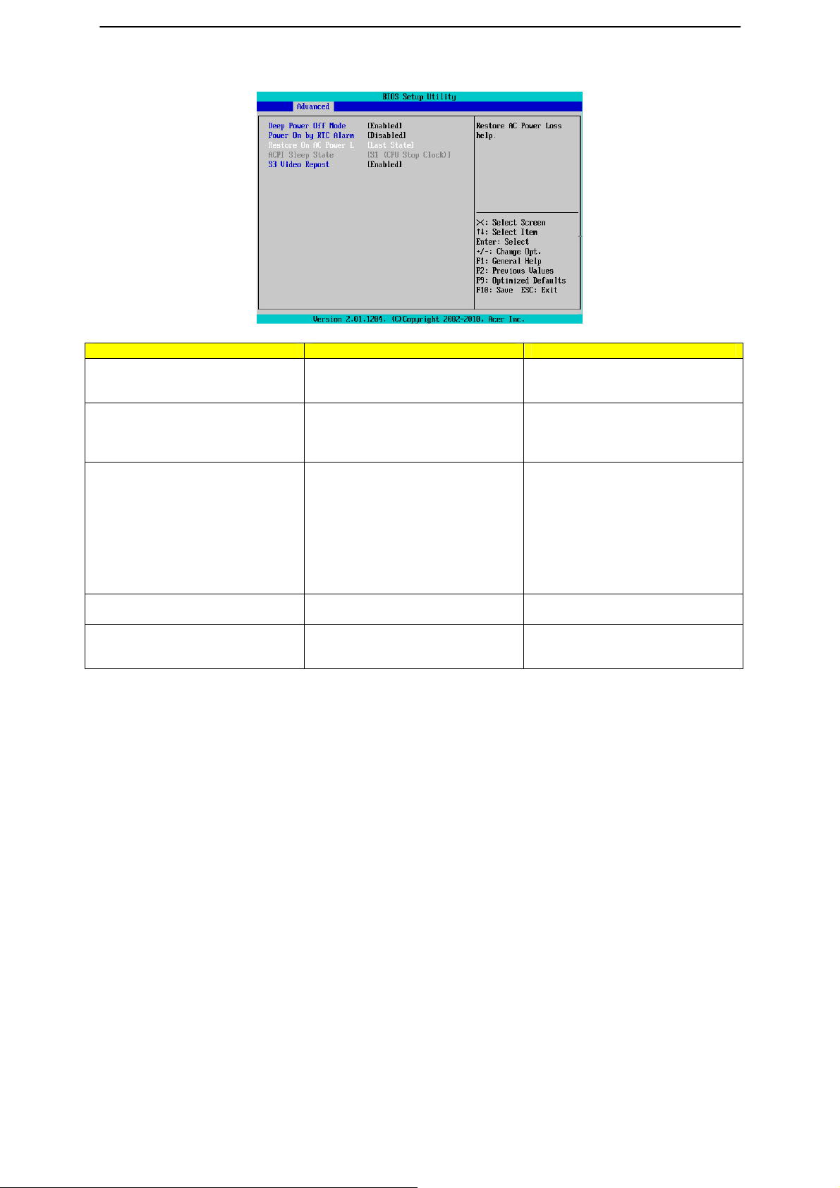
Power Configuration
Parameter Description Option
Deep Power Off Mode Enable or Disable Deep Power Off
Mode.
Power On by RTC Alarm
Restore on AC Loss Defines the power state to resume
ACPI Sleep State Displays ACPI Sleep State.
S3 Video Report Enable or Disable S3 Video Report. Enabled
Select whether to wake up the
system when an RTC alarm is
detected.
to after a sys- tem shutdown that is
due to an interruption in AC power.
When set to Last State, the system
will return to the active power state
prior to shutdown.
When set to Stay Off, the system
remains off after power shutdown.
Enabled
Disabled
Enabled
Disabled
Last State
Stay Off
Power On
Disabled
47

Hardware Monitor
Press Enter to view the Hardware Monitor screen which displays a real-time record of the CPU/system
temperature, fan speed, and voltage. Items on this window are non-configurable.
48
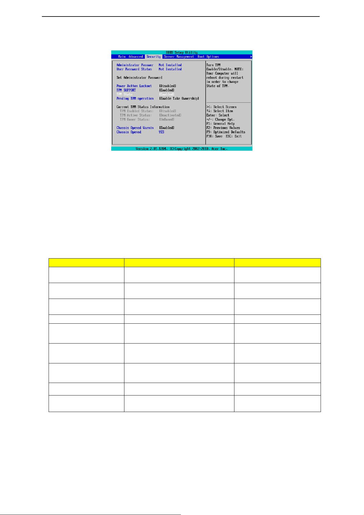
Security Menu
A
A
p
The Security menu allows you to safeguard and protect the system from unauthorized use by setting up
access passwords.
There are three types of passwords that you can set:
•
Administrator password
Entering this password will allow the user to access and change all settings in the Setup Utility.
•
User password
Entering this password will restrict a user’s access to the Setup menus. To enable or disable this
field, a Administrator Password must first be set. A user can only access and modify the System
Time, System Date, and Set User Password fields.
•
Power-on boot
When the Password on Boot fiel d i s ena bled, a password will be required to boot up th e se rver. To
enable or disable this field, a Administrator Password must first be set.
Parameter Description Option
dministrator Password
This parameter indicates whether a
dministrator Password has been assigned
User Password Status This parameter indicates whether a user
pass- word has been assigned.
Set Administrator Password Press Enter to configure the Administrator
password
Set User Password Press Enter to configure the user password.
Power Button Lockout Enable or disable Power Button Lockout Enabled
Not Installed
Enabled
Not Installed
Enabled
Disabled
TPM Support Select Enabled to activate TPM support
feature.
TPM State Select Enabled to activate TPM State
function.
Enabled
Disabled
Enabled
Disabled
Pending TPM Support Schedule TPM operation. None
Chassis Open Warning Enable or disable case open intrusion
function.
Enable Take Ownershi
Enabled
Disabled
49

Setting a System Password
1. Use the up/down keys to select a password parameter (Set Administrator Password or Set User Password),
then press Enter.
A password box will appear.
2. Type a password then press Enter.
The password may consist of up to six alphanumeric characters (A-Z, a-z, 0-9).
3. Retype the password to verify the first entry then press Enter again.
4. Press F10.
5. Select Yes to save the new password and close the Setup Utility.
Changing a System Password
1. Use the up/down keys to select a password parameter (Set Administrator Password or Set User Password),
then press Enter.
2. Type the original password then press Enter.
3. Type a new password then press Enter.
4. Retype the password to verify the first entry then press Enter again.
5. Press F10.
6. Select Yes to save the modified password and close the Setup Utility.
Removing a System Password
1. Use the up/down keys to select a password parameter (Set Administrator Password of Set User Password),
then press Enter.
2. Enter the current password then press Enter.
3. Press Enter twice without entering anything in the new and confirm password fields.
After doing this, the system automatically sets the related password parameter to Clear.
50

Server Menu
Parameter Description Option
System Information Displays basic system ID information, as well as
BIOS version.
Press Enter to access the related submenu.
Event Log Configuration Displays Event Log advanced settings.
Press Enter to access the related submenu.
51

System Information
The System Management submenu is a simple display page for basic system ID information, as well as
System product information. Items on this window are non-configurable.
52
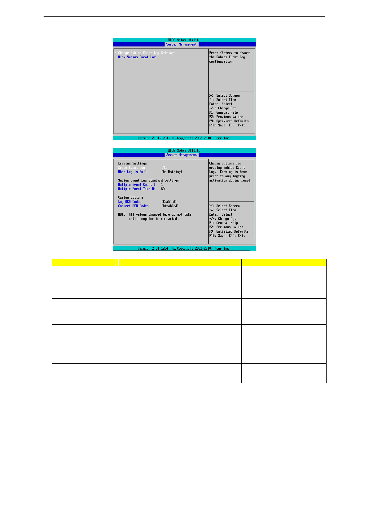
Event Log Configuration
Parameter Description Option
Change Smbios Event
Configuration
View Smbios Event Log Displ ays Smbios Event Log .
Erase Event Log Choose options for erasing Smbios Event Log
When Log is Full Choose options for reactions to a full Smbios
Log OEM Codes Enable or Disable the logging of EFI Status
Convert OEM Codes Enable or disable the converting of EFI Status
Press Enter to access the related submenu.
Press Enter to View Smbios Event Log
Erasing is done prior to any logging activation
during reset.
Event Log.
Codes as OEM Codes.
Codes to Standard Smbios Types.
No
Yes, next reset
Yes, every reset
Do Nothing
Erase immediately
Enabled
Disabled
Enabled
Disabled
NOTE: All values cha nged here do not take action until computer is resta rted.
53

Boot Option Menu
The Boot menu allows you to set the drive priority during system boot-up. BIOS setup will display an error
message if the drive(s) specified is not bootable.
By default, the server searches for boot devices in the following order:
1.
Hard drive
2. Optical disc drive
3. Removable device
4. Network device
5. UEFI device
Parameter Description Option
Hard Disk Drive Priority Press Enter to configure the boot priority.
Optical Disk Drive
Priority
Removable Disk Drive
Priority
Network Device Priority Press Enter to configure the boot priority.
UEFI Boot Device
Priority
Quiet Boot Enabled
Press Enter to configure the boot priority.
Press Enter to configure the boot priority.
Press Enter to configure the boot priority.
54
Disabled

Bootup NumLock State Enab le or Disable Bootup NumLock function. On
POST Error Pause Select whether to pause POST when a boot-up
error is detected.
Option ROM Messages Set display mode for Option ROM. Force BIOS
Watch Dog Timer Enable or d isable Watch Dog Timing function. Enabled
Off
Disabled
All, But Keyboard
All Errors
Keep Current
Disabled
55

Boot Manager Menu
The Boot manager menu allows you to specify the boot-up drive. BIOS setup will display an error
message if the drive(s) specified is not bootable.
Parameter Description Option
Built-in EFI Shell Press Enter to configure the device as the
boot-up drive.
IBA GE Slot 0100 v1350 Press Enter to configure the device as the
boot-up drive.
IBA GE Slot 0200 v1350 Press Enter to configure the device as the
boot-up drive.
56

Exit Menu
The Exit menu displays the various options to quit from the BIOS setup. Highlight any of the exit options then
press Enter.
Parameter Description Option
Save Changes and Exit Saves changes made and close the BIOS setup. Enabled
Discard Changes and Exit Discards changes made and close the BIOS
setup.
Save Changes Saves changes made in the BIOS setup. Enabled
Discard Changes Discards all changes made in the BIOS setup Enabled
Load Default Values Loads the default settings for all BIOS setup
parameters. Setup Defaults are quite demanding in
terms of resources consumption. If you are using
low-speed memory chips or other kinds of
low-performance components and you choose to load
these settings, the system might not function properly.
Save as User Default Values Saves as user default and cl ose the BIOS setup. Enabled
Load User Default Values Loads the user default settings for all BIOS setup
parameters.
Disabled
Enabled
Disabled
Disabled
Disabled
Enabled
Disabled
Disabled
Enabled
Disabled
57

Troubleshooting
Error Symptoms List
NOTE: To diagnose a problem, first find the error symptom in the left column. If directed to a check
procedure, replace the FRU indicated in the check procedure. If no check procedure is indicated, the first
Action/FRU listed in right column is the most likely cause.
Error Symptom
Processor / Processor Fan
NOTE: Normally, the processor fan should be operative, and the processor clock setting should be
exactly set to match its speed requirement before diagnosing any processor problems.
Processor fan does not run but power
supply fan runs.
Processor test failed.
Main board and Memory
NOTE: Ensure the memory modules are installed properly and the contact leads are clean before
diagnosing any system problems.
Memory test failed.
Incorrect memory size shown or repeated during
POST.
System works but fails to enter power
saving mode when the Power
Management Mode is set to Enabled.
Blinking cursor only; system does not work. 1. Diskette/IDE drive connection/cables
Hard Disk Drive
NOTE: Ensure hard disk drive is configured correctly in BIOS Setup, cable/jumper are set correctly before
diagnosing any hard disk drive problems. (If only one drive is installed, please make sure t he drive is
connected to master connector or the drive is set to master.)
Hard disk drive test failed.
Hard disk drive cannot format
completely.
1. Ensure the system is not in power saving mode.
2. With the system power on, measure the voltage
of processor fan connector. Its reading should
be +12Vdc. Its reading should be +12Vdc. If the
reading shows normal, but the fan still does not
work, then replace a good fan.
3. Main board.
1. Processor.
2. Main board.
1. See "Memory"
2. Main board
1. Insert the memory modules in the DIMM
sockets properly, then reboot the system.
2. Memory module.
3. Main board.
1. Enter BIOS Setup and load default settings.
2. Reload software from Recovery CD.
2. Diskette/IDE disk drives
3. See “Undetermined Problems”.
4. Main board
1. Enter BIOS Setup and Load default settings.
2. Hard disk drive cable.
3. Hard disk drive.
4. Main board.
1. Enter BIOS Setup and Load default settings.
2. Hard disk drive cable.
3. Hard disk drive.
Action/FRU
58

4. Main board.
Hard disk drive has write error.
Hard disk drive LED fails to light, but
system operates normally.
CD/DVD-ROM Drive
NOTE: Ensure CD/DVD-ROM drive is configured correctly in BIOS Setup, cable/jumper are set correctly
and its laser beam is clean before diagnosing any CD/DVD-ROM drive problems.
CD/DVD-ROM drive LED doesn't come
on but works normally.
CD/DVD-ROM drive LED flashes for
more than 30 seconds before LED
shutting off.
Software asks to reinstall disc.
Software displays a reading CD/DVD
error.
CD/DVD-ROM drive cannot load or eject
when the system is turned on and its
eject button is pressed and held.
CD/DVD-ROM drive does not read and
there are no messages are displayed.
CD/DVD-ROM drive can play audio CD
but no sound output.
Video and Monitor
Video memory test failed.
Video adapter failed.
Display problem:
- Incorrect colors
No high intensity
Missing, broken, or incorrect characters
Blank monitor (dark)
Blank monitor (bright)
Distorted image
Unreadable monitor
Other monitor problems
Display changing colors.
Display problem not listed above
1. Enter BIOS Setup and Load default settings.
2. Hard disk drive.
1. With the system power on, measure the voltage
of hard disk LED connector.
2. Hard drive LED cable.
1. CD/DVD-ROM drive
1. CD/DVD-ROM may have dirt or foreign material
on it.
Check with a known good disc.
2. CD/DVD-ROM is not inserted properly.
3. CD/DVD-ROM is damaged.
1. Disconnect all cables from CD/DVD-ROM drive
except power cable, then press eject button to
try to unload the disk.
2. CD/DVD-ROM drive power.
3. CD/DVD-ROM drive
1. CD may have dirt or foreign material on it.
Check with a known good disc.
2. Ensure the CD/DVD-ROM driver is installed
properly.
3. CD/DVD-ROM drive.
1. Ensure the headphone jack of the
CD/DVD-ROM has an output.
2. Turn up the sound volume.
3. Speaker power/connection/cable.
4. CD/DVD-ROM drive.
1. Remove all non-factory-installed cards.
2. Load default settings (if screen is readable).
3. Main board.
1. Monitor signal connection/cable.
2. Monitor
3. Video adapter card
4. Main board
1. Monitor signal connection/cable
2. Monitor
3. Main board
1. “Monitor"
59

(including blank or illegible monitor).
Parallel/Serial Ports
Execute “Load BIOS Default Settings” in BIOS Setup to confirm ports presence before diagnosing any
parallel/serial ports problems.
Serial or parallel port loop-back test failed. 1. Make sure that the LPT# or COM# you test is
Printing failed.
Printer problems.
Some or all keys on keyboard do not work.
Power Supply
Pressing power switch does not turn off system.
(Only unplugging the power cord from electrical
outlet can turn off the system.)
Pressing power switch does not turn on the system. 1. Ensure the power override switch (situated at
Executing software shutdown from
Windows98 Start menu does not turn off
the system. (Only pressing power switch can turn off
the system).
No system power, or power supply fan is not
running.
Other Problems
Any other problems. 1. Undetermined Problems
2. Load default settings (if screen is readable).
3. Main board
the same as the setting in BIOS Setup.
2. Loop-back.
3. Main board.
1. Ensure the printer driver is properly installed.
Refer to the printer service manual.
2. Printer.
3. Printer cable.
4. Main board.
1. Refer to the service manual for the printer.
Keyboard
1. Keyboard
1. Ensure the AC-LINK in BIOS Setup of Boot
Configuration is not set to Stay-off.
2. Power switch cable assembly
the back of the machine, just above the
connector for the power cable) is not set to
OFF.
2. Power switch cable assembly.
1. Load default settings.
2. Reload software from Recovery CD.
1. Power Supply
2. Main board
60

BIOS Beep Codes
BIOS Beep Codes Table
PEI Beep Codes
# of Beeps Description
1 Memory not Installed.
1 Memory was installed twice (InstallPeiMemory routine in PEI Core called twice)
2 Recovery started
3 DXEIPL was not found
3 DXE Core Firmware Volume was not found
4 Recovery failed
4 S3 Resume failed
7 Reset PPI is not available
DXE Beep Codes
# of Beeps Description
1
4
5
5
6
7
8
BIOS Recovery Instruction
AMI has an embedded recovery technique. In the event that the BIOS becomes corrupt the boot block can be used to
restore the BIOS to a working state. To restore your BIOS, please follow the instructions listed below:
Recovery Instruction:
Invalid password
Some of the Architectural Protocols are not available
No Console Output Devices are found
No Console Input Devices are found
Flash update is failed
Reset protocol is not available
Platform PCI resource requirements cannot be met
1 Prepare a bootable handy drive or floppy diskette
2 Copy the image file to the bootable hand drive or the bootable floppy diskette.
3 Rename the image file to "FLASHABL.ROM".
61

Figure 300-03
62

Recovery Stage
4 Connect the disk, here we use FAT disk and set recovery jumpe r. Then system would enter
BIOS Setup Menu. You may see the page as the following figures shows.
5 Enter “Proceed with flash update” page, the system would recover the BIOS image automically.
6 When recovery process is completed, reset the system.
63

BIOS POST Error Messages List
BIOS POST error message list
PEI Phase
Status Code Description
Progress Code
0x10 PEI Core is started
0x11 Pre-memory CPU initialization is started
0x12 Pre-memory CPU initialization (CPU module specific)
0x13 Pre-memory CPU initialization (CPU module specific)
0x14 Pre-memory CPU initialization (CPU module specific)
0x15 Pre-memory North Bridge initialization is started
0x16 Pre-Memory North Bridge initialization (North Bridge module specific)
0x17 Pre-Memory North Bridge initialization (North Bridge module specific)
0x18 Pre-Memory North Bridge initialization (North Bridge module specific)
0x19 Pre-memory South Bridge initializatio n is started
0x1A Pre-memory South Bridge initialization (South Bridge module specific)
0x1B Pre-memory South Bridge initialization (South Bridge module specific)
0x1C Pre-memory South Bridge initialization (South Bridge module specific)
0x1D – 0x2A OEM pre-memory initialization codes
0x2B Memory initialization. Serial Presence Detect (SPD) data reading
0x2C Memory initialization. Memory presence detection
0x2D Memory initialization. Programming memo ry timing information
0x2E Memory initialization. Configuring memory
0x2F Memory initialization (other).
0x30 Reserved for ASL (see ASL Status Codes section belo w)
0x31 Memory Installed
0x32 CPU post-memory initialization is started
0x33 CPU post-memory initialization. Cache initialization
0x34 CPU post-memory initialization. Application Processor(s) (AP) initialization
0x35 CPU post-memory initialization. Boot Strap Processor (B SP) selection
0x36 CPU post-memory initialization. System Manageme nt Mode (SMM) i nitialization
0x37 Post-Memory North Bridge initialization is started
0x38 Post-Memory North Bridge initialization (North Bridge module specific)
0x39 Post-Memory North Bridge initialization (North Bridge module specific)
0x3A Post-Memory North Bridge initialization (North Bridge module specific)
0x3B Post-Memory South Bridge initialization is started
0x3C Post-Memory South Bridge initialization (South Bridge module specific)
0x3D Post-Memory South Bridge initialization (South Bridge module specific)
0x3E Post-Memory South Bridge initialization (South Bridge module specific)
0x3F-0x4E OEM post memory initialization codes
0x4F DXE IPL is started
PEI Error Codes
0x50 Memory initialization error. Invalid memory t ype or incompatible memory speed
0x51 Memory initialization error. SPD reading h as failed
0x52 Memory initialization error. Invalid memory size or memory modules do not
match.
0x53 Memory initialization error. No usable memory detected
0x54 Unspecified memory initialization error.
0x55 Memory not installed
0x56 Invalid CPU type or Speed
0x57 CPU mismatch
0x58 CPU self test failed or possible CPU cache error
0x59 CPU micro-code is not found or micro-code update is failed
64

0x5A Internal CPU error
0x5B Reset PPI is not avai lable
0x5C-0x5F Reserved for future AMI error codes
S3 Resume Progress Codes
0xE1=0 S3 Resume is stared (S3 Resume PPI is called by the DXE IPL)
0xE1 S3 Boot Script execution
0xE2 Video repost
0xE3 OS S3 wake vector call
0xE4-0xE7 Reserved for future AMI progress codes
S3 Resume Error Codes
0xE8 S3 Resume Failed
0xE9 S3 Resume PPI not Found
0xEA S3 Resume Boot Script Error
0xEB S3 OS Wake Error
0xEC-0xEF Reserved for future AMI error codes
Recovery Progress Codes
0xF0 Recovery condition triggered by firmware (Auto recovery)
0xF1 Recovery condition triggered by user (Forced recovery)
0xF2 Recovery process started
0xF3 Recovery firmware image is found
0xF4 Recovery firmware image is loaded
0xF5-0xF7 Reserved for future AMI progress codes
Recovery Error Codes
0xF8 Recovery PPI is not available
0xF9 Recovery capsule is not found
0xFA Invalid recovery capsule
0xFB – 0xFF Reserv ed for future AMI error codes
DXE Phase
Status Code Description
0x60 DXE Core is started
0x61 NVRAM initialization
0x62 Installation of the South Bridge Runtime Services
0x63 CPU DXE initialization is started
0x64 CPU DXE initialization (CPU module specific)
0x65 CPU DXE initialization (CPU module specific)
0x66 CPU DXE initialization (CPU module specific)
0x67 CPU DXE initialization (CPU module specific)
0x68 PCI host bridge initialization
0x69 North Bridge DXE initialization is started
0x6A North Bridge DXE SMM initial ization is started
0x6B North Bridge DXE initialization (North Bridge module specific)
0x6C North Bridge DXE initialization (North Bridge module specific)
0x6D North Bridge DXE initialization (North Bridge module specific)
0x6E North Bridge DXE initialization (North Bridge module specific)
0x6F North Bridge DXE initialization (North Bridge module specific)
0x70 South Bridge DXE initialization is started
0x71 South Bridge DXE SMM initialization is started
0x72 South Bridge devices initialization
0x73 South Bridge DXE Initialization (South Bridge module specific)
0x74 South Bridge DXE Initialization (South Bridge module specific)
0x75 South Bridge DXE Initialization (South Bridge module specific)
0x76 South Bridge DXE Initialization (South Bridge module specific)
0x77 South Bridge DXE Initialization (South Bridge module specific)
0x78 ACPI module initialization
0x79 CSM initialization
65

0x7A – 0x7F Reserved for future AMI DXE codes
0x80 – 0x8F OEM DXE initialization codes
0x90 Boot Device Selection (BDS) phase is started
0x91 Driver connecting is started
0x92 PCI Bus initialization is started
0x93 PCI Bus Hot Plug Controller Initialization
0x94 PCI Bus Enumeration
0x95 PCI Bus Request Resources
0x96 PCI Bus Assign Resources
0x97 Console Output devices connect
0x98
0x99
0x9A
0x9B USB Reset
0x9C USB Detect
0x9D USB Enable
0x9E – 0x9F Reserved for future AMI code s
0xA0 IDE initialization is started
0xA1 IDE Reset
0xA2 IDE Detect
0xA3 IDE Enable
0xA4 SCSI initialization is started
0xA5 SCSI Reset
0xA6 SCSI Detect
0xA7 SCSI Enable
0xA8 Setup Verifying Password
0xA9 Start of Setup
0xAA Reserved for ASL (see ASL Status Codes section below)
0xAB Setup Input Wait
0xAC Reserved for ASL (see ASL Status Codes section below)
0xAD Ready To Boot event
0xAE Legacy Boot event
0xAF Exit Boot Services event
0xB0 Runtime Set Virtual Address MAP Begin
0xB1 Runtime Set Virtual Address MAP End
0xB2 Legacy Option ROM Initialization
0xB3 System Reset
0xB4 USB hot plu g
0xB5 PCI bus hot pl ug
0xB6 Clean-up of NVRAM
0xB7 Configuration Reset (reset of NVRAM settings)
0xB8 – 0xBF Reserved for future AMI codes
0xC0 – 0xCF OEM BDS initialization codes
DXE Error Codes
0xD0 CPU initialization error
0xD1 North Bridge initialization error
0xD2 South Bridge initialization error
0xD3 Some of the Architectural Protocols are not available
0xD4 PCI resource allocation error. Out of Resources
0xD5 No Space for Legacy Option ROM
0xD6 No Console Output Devices are found
0xD7 No Console Input Devices are found
0xD8 Invalid password
0xD9 Error loading Boot Option (LoadImage returned error)
0xDA Boot Option is failed (StartImage returned error)
0xDB Flash update is failed
0xDC Reset protocol is not available
Console input devices connect
Super IO Initialization
USB initialization is started
66

Undetermined Problems
If an error message is present, go to “POST Error Messages List” on page 64. If you did not
receive any messages, if the symptom is listed in “or “Error Symptoms List” on page 60. If you still
cannot solve the problem, continue with this check:
1. Check the power supply voltages. If the voltages are correct continue with the
following steps:
2. Power off the system unit.
3. Perform the following checks, one by one, until you have isolated the problem FRU.
4. Load default settings in setup.
5. Check all main board jumper positions and switch settings.
6. Check all adapter card jumper positions.
7. Check all device jumper positions.
8. Check all cables and connectors for proper installation.
9. If the jumpers, switches and voltage settings are correct, remove or disconnect the
following, one at a time:
10. Non-Acer devices
External devices
Any adapter card (modem card, LAN card or video card, if installed)
CD/DVD-ROM drive
Diskette drive
Hard disk drive
DIMM
Processor
Main board
11. Power on the system unit.
12. Repeat steps 2 through 5 until you find the failing device or adapter.
67
 Loading...