

Page 1

Gateway Series
G100 / G200 / G400 / G800
Administr ato r Man ual
601-00020 Rev. B
Page 2

445 Jan Davis Drive
Digium, Inc.
Huntsvil le, AL 35806
United States
Main Number: +1 (256)-428-6000
Tech Support: +1 (256)-428-6161
U.S. Toll Free: +1 (877)-344-4861
Sales: +1 (256)-428-6262
www.digium.com
www.asterisk.org
www.asterisknow.org
© Digium, Inc. 2013
All rights reserved.
No part of this publication may be copied, distributed, transmitted, transcribed, stored in a
retri eval s yst em , o r tran sl at ed int o a ny hu man or co mpu ter l angu ag e wit h ou t the p rio r wr i tte n
permission of Digium, Inc.
Digium, Inc. has made every effort to ensure that the instructions contained in this document
are ade q uate an d err o r free. The m a nu fa ct u rer will, if n ec es s ar y , ex pl ain issu es whic h m ay
not be covered by this documentation. The manufacturer’s liability for any errors in the
docume nts is limi ted to the cor rection of errors and the aforementioned advisory services.
This doc ument h as been p repar ed for us e by profe ssiona l and pr operly tr ained p ersonn el,
and the cus to m er as su m es fu ll re sp onsibi li ty w he n us in g it .
Adobe and Acrobat are registered trademarks, and Acrobat Reader is a trademark of Adobe
Systems Incorporated.
Asterisk, Digium, Switchvox, and AsteriskNOW are registered trademarks and Asterisk
Business Edition, AsteriskGUI, and Asterisk Appliance are trademarks of Digium, Inc.
Any oth er tr a dem ark s m en ti oned i n t he do cu me nt ar e t he pr op ert y of t h ei r r es pe ctiv e ow ner s.
Digium, Inc. Page 2
Page 3

Compliance Information
Compliance information for this product is available at
http://www.digium.com/compliance.
Digium, Inc. Page 3
Page 4

Introduction to Gateway Series Documentation
This manual contains product information for the Gateway Series
appliances. Be sure to refer to any supple mentary documents or release
notes that were shipped with your equipment. The manual is organized in
the following manner:
Chapter/
Appendix
1
2
3
4
A
B
C
Overview Identifies the features of your unit.
Unit Installation Provides instructions for installing the unit.
Configuration Provides instructions on how to configure the un it.
Troublesh ooting Explains resolut ions to common problems and
Pin Assignments Describes the states supported by the unit.
Specifications Details unit specifications.
Glossary and
Acronyms
Title Description
frequentl y as ked questions per taining to unit
installation and usage.
Defines terms related to this product.
Digium, Inc. Page 4
Page 5

Symbol Definitions
Caution stat emen ts in dicate a c onditio n whe r e d amage to t he un it o r
its configuration could occur if operational procedures are not
followed. To reduce the risk of damage or injury, follow all steps or
procedures as instructed.
The ESD sym b o l in d i ca t es electrostat i c s en si ti ve d e vi ces. Obser v e
prec autions for handling devices. Wear a prop er ly grounded
electrostatic discha rge (ESD) wrist strap while handling the device.
The Electrical Hazard Symbol indicates a possibility of electrical
shock when operat ing this unit in certain situations. To reduce the
risk of damage or injury, fol low all steps or proc edures as
instructed.
Digium, Inc. Page 5
Page 6

Important Safety Instructions
Servicing.
Do not attempt to service this unit. There are no user-serviceable
parts inside. Refer servicing to qualified service personnel.
Batteries.
The batteries in the unit are not user-servic eable. Refer servicing to
qualified service personnel.
CAUTION - Risk of explosion if battery is replaced by an incorrect
type. Batter ies should be disposed of according to the local laws and
regulations of your region.
ATTENT ION - II y a danger d’ex plosion s’il y a remplacement
incorrect de la batterie. Remplacer uniquement avec une batterie du
même type ou d’un type equivalent recommandé par le
constructeur.Mettre au rebut les batteries usages conformément aux
instructions du fabricant.
Water and Moisture.
Do not spill liquids on this unit. Do not operate this equipment in a
wet environmen t.
Heat.
Do not operate or store this product near heat sources such as
radiators, air ducts, areas subject to di rect, intense sunlight, or other
products that produce heat.
Caution.
To reduce the risk of fire, use only No. 26 AWG or larger
telecommunication wiring for network connections.
Static Electricity.
To reduce the risk of damaging the unit or your equipment, do not
attempt to open the e nclosure or gain access to areas w here you are
not instructed to do so. Refer servicing to qualified service personnel.
Save these instructions for future reference.
Digium, Inc. Page 6
Page 7

TABLE OF CONTENTS
Chapter 1
Overview . . . . . . . . . . . . . . . . . . . . . . . . . . . . . . . . . . . . . . . . . . . . . . .11
Chapter 2
Unit Installation . . . . . . . . . . . . . . . . . . . . . . . . . . . . . . . . . . . . . . . . . .16
Chapter 3
Configuration . . . . . . . . . . . . . . . . . . . . . . . . . . . . . . . . . . . . . . . . . . . .45
Chapter 4
Troubleshooting . . . . . . . . . . . . . . . . . . . . . . . . . . . . . . . . . . . . . . . . .77
Echo-Cancellation . . . . . . . . . . . . . . . . . . . . . . . . . . . . . . . . . . . . . .15
Unpacking the Unit . . . . . . . . . . . . . . . . . . . . . . . . . . . . . . . . . . . . .17
Shipment Inspection . . . . . . . . . . . . . . . . . . . . . . . . . . . . . . . . . . . .18
Front Panel Identification . . . . . . . . . . . . . . . . . . . . . . . . . . . . . . . .19
Unit Identification . . . . . . . . . . . . . . . . . . . . . . . . . . . . . . . . . . . . . .23
Hardware Installation . . . . . . . . . . . . . . . . . . . . . . . . . . . . . . . . . . . 24
Connecting to the Gateway S eries . . . . . . . . . . . . . . . . . . . . . . . . .33
Settings and Configuration . . . . . . . . . . . . . . . . . . . . . . . . . . . . . . .49
Logging and Reporting . . . . . . . . . . . . . . . . . . . . . . . . . . . . . . . . . .65
Status and Diagnostics . . . . . . . . . . . . . . . . . . . . . . . . . . . . . . . . . .66
Maintenance . . . . . . . . . . . . . . . . . . . . . . . . . . . . . . . . . . . . . . . . . .72
Frequently Asked Questions . . . . . . . . . . . . . . . . . . . . . . . . . . . . . .80
Free Installation Support . . . . . . . . . . . . . . . . . . . . . . . . . . . . . . . . .84
Digiu m, In c . Page 7
Page 8

Table Of Contents
Appendix A
Pin Assignments . . . . . . . . . . . . . . . . . . . . . . . . . . . . . . . . . . . . . . . . .85
Appendix B
Specifications . . . . . . . . . . . . . . . . . . . . . . . . . . . . . . . . . . . . . . . . . . .8 7
Appendix C
Glossary and Ac ronyms . . . . . . . . . . . . . . . . . . . . . . . . . . . . . . . . . . .8 9
Digium, Inc. Page 8
Page 9

List of Figures
Figure 1: TDM PBX to VoIP Scenario . . . . . . . . . . . . . . . . . . .13
Figure 2: VoIP PBX to TDM Scenario . . . . . . . . . . . . . . . . . . .13
Figure 3 : TDM PBX to TDM and VoIP Scena rio . . . . . . . . . . .14
Figure 4: G100 Single Port Appliance . . . . . . . . . . . . . . . . . . .19
Figure 5: G200 Dual Port Appliance . . . . . . . . . . . . . . . . . . . . 20
Figure 6: G800 Octal Port Appliance . . . . . . . . . . . . . . . . . . . .21
Figure 7 : Side-by-side Rack Mounting . . . . . . . . . . . . . . . . . . .29
Figure 8: Acceptable Wall Mount Orientation . . . . . . . . . . . . .30
Figure 9: IP Configuration Menu for G100 / G200 . . . . . . . . . .36
Figure 10: IP Configuration Menu fo r G400 / G800 . . . . . . . . . .40
Figure 1 1: Login Screen . . . . . . . . . . . . . . . . . . . . . . . . . . . . . . .46
Figure 12: Main Menu . . . . . . . . . . . . . . . . . . . . . . . . . . . . . . . .48
Digium, Inc. Page 9
Page 10

List of T able s
Table 1: Gateway Series Models. . . . . . . . . . . . . . . . . . . . . . 23
Table A-1: Gigabit Ethernet Port Pinouts . . . . . . . . . . . . . . . . . .85
Table A-2: RJ45 T1/E1 Port Connector . . . . . . . . . . . . . . . . . . . . 86
Digium, Inc. Page 10
Page 11

Chapter 1 Overview
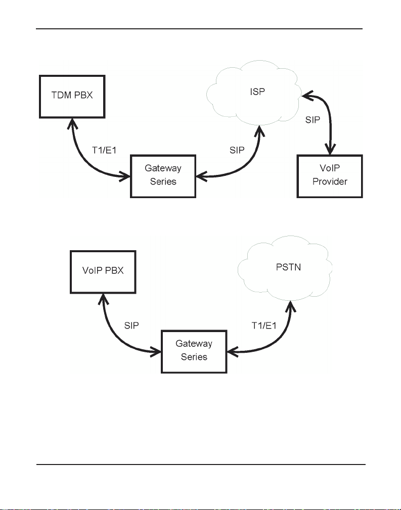
Digium's Gateway Series is a converged media gateway product line
designed to interface between TDM (T1/E1) and IP networks (SIP). The
Gateway Series connects lega cy tele phone systems to IP networks and
seamlessly integr ates VoIP PBXs with the PSTN. Powered by innovative
hardware and software solut ions, Digium’s Gateway Series are managed
by a simple, intuitive web-based interface.
Digiu m, In c . P age 1 1
Page 12

Supported V oice Modes:
Chapter 1: Overview
PRI CPE and PRI NET (T1 / E1)
– National ISDN 1 / NI1
– National ISDN 2 / NI2
– EuroISDN
– 4ESS (AT&T)
– 5ESS (Lucent)
– DMS100
– Q.SIG
E&M (T1 only)
– Wink
– Feature Group B
– Feature Group D
FXO and FXS (T1 only)
– Ground Start
– Loop Start
– Loop Start with Disconnect Detect (Kewls ta rt)
SIP
Example scenarios utiliz ing the Gateway Series are i llustrated in Figur e 1,
Figure 2, and Figure 3.
Digium, Inc. Page 12
Page 13
Chapter 1: Overview
Figure 1: TDM PBX to VoIP Scenario
Figure 2: V oIP PBX to TDM Sc en ario
Digium, Inc. Page 13
Page 14

Chapter 1: Overview
Figure 3: TDM PBX to TDM and VoIP Scenario
Digium, Inc. Page 14
Page 15

Echo-Cancellation
Chapter 1: Overview
Administrators connecting their Gateway Series appliances to the PSTN
or other devices are likely to be placing calls that will result, at some
point, in an unbalanced 4-wire/2-wire hybrid. The result of this hybrid is
the reflection of a near-end echo to the calling party. Elimination of this
echo is the responsibility of echo cancellation.
The Gateway Series appliance utilizes hardware-based voice processors
for echo cancellation an d codec tra nscoding. Its hardware echo canceller
is designed to handl e up to 128m s of e cho cancel lation ac ross a ll channe ls
and provides a G.168 compliant echo cancellation solution.
If not explicitly disable d in the Gateway Series web GUI, the hardwarebased echo canceller will automatically operate and cancel all network
echo within its tail range (1024 taps).
Digium, Inc. Page 15
Page 16

Chapter 2 Unit Installation
This chapter provides the following information:
Unpacking the Unit on page 17
Sh i pment Inspecti o n on page 18
Front Panel Identification on page 19
U nit I den ti fica ti on on page 23
Hardware Installation on page 24
Note: The Gateway Series applia nce installation instruct ions are
written so that they will apply to any model in the series. Examples
and model specific information are included as needed.
Digiu m, In c . Page 16
Page 17

Unpacking the Unit
Chapter 2: Unit Installation
When you unpack your unit, carefully inspect it for any damage that m ay
have occurred in shipment. If damage is sus pected, file a claim with the
carrier and contact the reseller from which the unit was purchased. If the
unit was purchased direct ly from Digium, contact Digium Technical
Support at +1 (256)-428-6161. Keep the original shipping container to
use for future shipment or proof of damage during shipment.
Note: Only qualified service personnel should install t he unit. Users
should not attempt to perform thi s function themselves. The installer
must ensure that the equipment is reliably earth grounded in
accordance with the National Electrical Code.
Digium, Inc. Page 17
Page 18

Chapter 2: Unit Installation
Shipment Inspection
The following items are includ ed in shipment of a Gateway Series
appliance:
Gateway Series appliance
Power cord with attached T1/E1 loopback plug
M ounting brackets (2 each)
Bracket mounting screws, #8-32 black truss head, Philli ps, 3/16”
Side-by-side mounting screws, #6-32 pan head, Phillips, 3/16” length
length (6 each)
(3 each)
Side-by-side mounting shoulder washers (3 each)
Rubber feet (4 each)
Ground nut
Double-crimp ground ring terminal
Quickstart Guide
Note: After inspecting the shipment, Digium requires that the
appliance be registere d for support eligibi lit y. Unregister ed appliances
are not eligible for Digium suppo rt. Please refer to Free Installation
Support on page 84 for additional information on how to obtain
assistance from Digium Technical Support.
Digium, Inc. Page 18
Page 19

Chapter 2: Unit Installation
USB
Recovery
T1/E1
Gigabit
Status
Ethernet
Device
Status
Ethernet
Status
T1/E1
Port
Front Panel Identification
This section describes the components on the front panel of the Gateway
Series models.
Figure 4: G100 Single Port Appliance
Digium, Inc. Page 19
Page 20

Chapter 2: Unit Installation
USB
Recovery
T1/E1
Gigabit
Status
Ethernet
Device
Status
Ethernet
T1/E1
Status
Port
Figure 5: G200 Dual Port Appliance
Digium, Inc. Page 20
Page 21

Chapter 2: Unit Installation
USB
Recovery
T1/E1
Gigabit
Status
Reset
Ethernet
Device
Status
Ethernet
T1/E1
Status
Port
Figure 6: G800 Octal Port Appliance
Device Status - This LED corresponds to the status of the Gateway
Series appliance. See Frequently Asked Questions on page 80 for
more information.
Gigabit Ethernet - The 10/100/1000BaseT Ethernet port(s) provides
the ability to connect to an int erna l or external network using an RJ45
interface and support s Auto-MDIX. It is used to pass Ethernet packetized voice and web management data between the Gateway Series
and the network. See Gigabit Ethernet Port Pinouts on page 85 for
more information.
Second Gigabit Ethernet (G400/G800 only) - The second 10/100/
1000BaseT Ethernet port(s) provides the ability to connect to an internal or external network using an RJ45 interface and supports AutoMDIX. It is used to pass Ethernet packetized voice and web management data betwe en the Gateway Series and the network. See Gigabit
Ethernet Port Pinouts on page 85 for more information.
Digium, Inc. Page 21
Page 22

Chapter 2: Unit Installation
Ethernet Stat us - The se LEDs correspond to the status of the Ethernet
connection. See Frequently Asked Questions on page 80 for more
information.
USB Recovery - This port can be used to perform a firmware recovery
and configuration reset. See Fi rmwar e Recovery and Configurat ion
Reset on page 78 for more information.
Warning! The USB Recovery port provides a limited amount of
current which is suf ficient only to power a USB flash drive. Do not
connect any other type of device to this port. The USB flash drive
should be fully USB 2.0 compliant.
T1 /E 1 Po rt(s) - These ports are used for connecting T1 or E1 cables.
See RJ45 T1/E1 Port Connector on page 86 for more informat io n.
T1 /E1 Status - These LEDs corr es po nd to the st at us of the T 1/E1
ports. See Frequently Asked Questions on page 80 for more infor-
mation.
Reset Switch (G400/G800 only) - This recessed switch is used to
restart the Gateway Serie s appliance or reset its GUI password. See
Frequently Asked Questions on page 80 for more information.
Digium, Inc. Page 22
Page 23

Chapter 2: Unit Installation
Unit Identification
The defining character istic of the Gateway Series models are the number
of T1/E1 and Ethernet ports supporte d. S ee Table 1 for a list of the
various models.
Table 1: Gateway Series Models
Model Type T1/E1 Ports Ethernet Ports
G100 T1/E1 1 1
G200 T1/E1 2 1
G400 T1/E1 4 2
G800 T1/E1 8 2
Digium, Inc. Page 23
Page 24

Hardware Installat ion
Chapter 2: Unit Installation
This sectio n describes how to properly inst all the hardware for a Gateway
Series appliance.
Caution
Only qualified service personnel should continue with
hardware installation and configuration of the Gateway Series
appliance. Users should not attempt to perform these functions
themselves.
Caution
This equ ipmen t is i nt e n d e d fo r u s e in Restricted Ac ce s s A reas
only where equipotential bonding has been applied.
Grounding
The Gateway Series appliance must be proper ly earth gr ounded for safety
reasons. If the unit is not properly earth grounded, the unit and/or other
equipment connected to the unit could be damaged. If a Gateway Series
appliance is damaged while it is imprope rly grounded, the warranty on
the Gateway Series appliance is void.
A ground lug is located on the opposite side from the front panel of a
Gateway Series a pplian ce. Atta ch an a ppropr iate l eng th and gauge of wire
to the double-crimp ground ring terminal. The wire length should be as
short as possible, and gauge should be 18 AWG or greater. Stra nded or
solid wire is acceptable . Wire is not provided with the Gateway Series
Digium, Inc. Page 24
Page 25

Chapter 2: Unit Installation
appliance. Double crimp the ground ring terminal to the wire. Next, slide
the ground ring terminal over the ground lug. Then fasten the ground ring
terminal to the ground lug using the gro und nut. The ground nut must be
turned clockwis e to tigh ten it o nto th e groun d lug. The opposite end of the
wire that is connected to the ground ring terminal should be securily
fastened to an unpainted metalic section of a properly earth grounded
equipment rack. A connector for the opposite end of the wire is not
provided with the Gateway Series appliance.
Note: Taking into considera tion the requirements of all equipment
connected to or sharing the rack, the equipment rack should be
properly earth grounde d. Ref er to the manu facturer of the rack for
instructions on how to properly e arth ground the rack.
Important
Use only a grounded electrical outlet when connecting the
Gateway Series appliance to a power sour ce. If you do not
know whether the outlet is grounded, consult wi th a qualified
electrician.
Digium, Inc. Page 25
Page 26

Chapter 2: Unit Installation
Mounting
The included hardware allows the Gate way Serie s appliance to be wall
mounted, rack mounted side-by-side with another Gateway Series
appliance, or placed flat on a leve l surface. If a single Gateway Series
appliance is to be rack mounted, the optional long mounting bracket (not
supplied, part number 3244-00042) must be used. The optional long
mounting bracket can be ordered by contacting a Digium reseller or
Digium directly.
Important
Reliable ear th grounding of ra ck-mount equipment should be
maintained. Particular atte ntion should be given to provide
connection other than direct connections to the branch circuit
(e.g., use of power strips).
Important
Mounting of the Gateway Series appliance in a rack should be
such that no hazardous condition is achieved due to uneven
mechanical loading. Do not place heavy obje cts on top of the
unit, or pull down on the mounted unit. Consider the
mechanical l oadi ng of ex terna l cable s. The wei ght of th e cable s
can pull on the unit and create unev en loading. Secure heavy
cables with external cable trays.
Important
If rack mounting, ins tall the Gateway Ser ies appliance in a rack
so that the amount of airflow r equired for safe operation is not
compromised.
Digium, Inc. Page 26
Page 27

Chapter 2: Unit Installation
Important
If the Gateway Series appliance is installed in a system that is
in turn installed in a closed or mu lti-unit rack ass embly, the
operating ambient temperature of the rack environment may be
signific antly greater t han the room ambient. Whi le the
maximum safe operat ing temperature is 50°C, consideration
should be given to ins talling the unit in an environment
compatible with the maximum recommended ambient
temperature of 45°C for long ter m reliabili ty and maximum
performance.
Single Unit Rack Mount:
In order to rack mount the Gateway Series appliance by itself, place one
of the short mounting brackets on the front of one side of the Gateway
Series appliance. Line up the hole s from the mounting bracket to the
threaded holes on the front sid e of the Gateway Ser ies appliance. Two #8
black truss head sc rews should be inserted and tur ned clockwise to fasten
the mounting bracket. Do not over-tighten. Repeat these steps when
installing the optional long mounting bracket (not supplied, part number
3244-00042) on the othe r side of the Gateway Series appl iance. Then use
another 2 #8 black truss head screws on each mounting bracket to secure
the Gateway S eries ap pl ian ce to a rack .
Digium, Inc. Page 27
Page 28

Chapter 2: Unit Installation
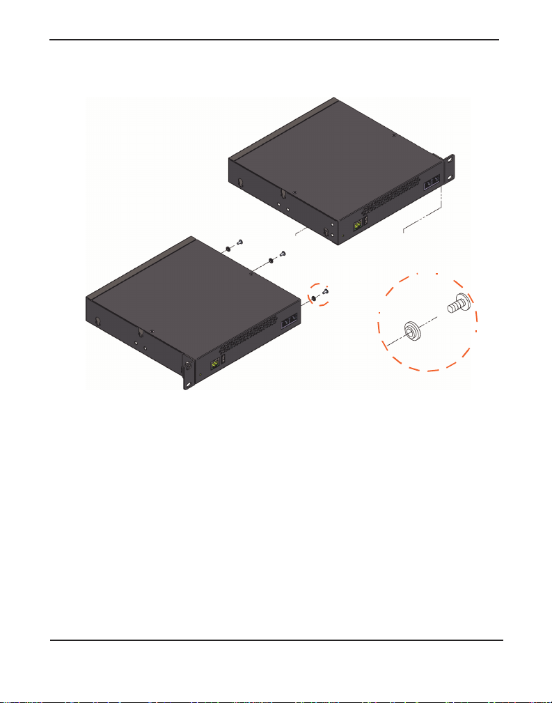
Side-by-s ide Rack Mount:
In order to rack mount the Gateway Series appliance side-by-side with
another Gateway Series appliance, place one of the short mounting
brackets on the front of the le ft side of the first Gateway Serie s appliance.
Line up the holes from the mounting bracket to the threaded holes on the
front of the left side of the first Gateway Series appliance. Two #8 black
truss head screws should be inserted and turned clockwise to fasten the
mounting bracket. Repeat these steps when installing a short mounting
bracket on the front of the right sid e of the seco nd Gateway Series
appliance.
Each of the three #6 pan head screws should be inserted into a shoulder
washer as shown in Figur e 7 on page 29. Make sur e the narr ow side of the
shoulder washer is away from the head of the screw. The three screws
should then be insert ed and turned clockwise to fasten to th e si de-by-side
holes on the right side of the first Gate way Serie s appliance. Do not
overtighten the screws or th e shoulder washers could be damaged.
Connect the first and second Gatewa y Series appliances together by
putting the heads of three screws & shoulder washers into the thre e keyed
insets. Then push down on th e second Gateway Ser ies applia nce a s sh own
in Figure 7. Make sure the units a re flat against each other before pushing
the second unit down. Otherwise the shoulder washers may be damaged.
Use two truss head screws (not supplied) on each mounting bracket to
secure both Gateway Series appl iances to a rack.
Digium, Inc. Page 28
Page 29
Chapter 2: Unit Installation
Figure 7: Side-by-side Rack Mounting
Wall M ount :
In order to wall mount the Gateway Series appliance, the short mounting
brackets should be flipped an d rotate d, a nd fastened on the middle of the
right and left sides of the Gateway Series appliance as shown in Figure 8
on page 30. The unit should be mounted at or below eye level to pr operly
view the LEDs. In addition, the Gateway Series appli ance s hould be
properly oriented as shown in Figu re 8. Ori entations other than what is
shown in Figu re 8 are not acce p ta ble .
Digium, Inc. Page 29
Page 30

Chapter 2: Unit Installation
Right side down
Front side
Back side
Left side
Right side
If the Gateway Series applian ce is pla ced in the “right side down”
orientation, the 2 remaining #8 black truss head mounting screws should
be fully inser ted into the screw hole s near the front of the right side of the
Gateway Series applianc e. In ad dition, the three #6 pan head screws
should be ful ly inserted into the side-by-side holes on the right sid e of the
first Gateway Series appl iance.
Note: The Gateway Series appliance must be properly grounded for
safety reaso ns. I f the uni t i s not prope rly groun ded, d amage coul d a rise
to the unit and/or other equipment connected to the unit.
Figure 8: Acceptable Wall Mount Orientation
Digium, Inc. Page 30
Page 31

Level Surface:
Chapter 2: Unit Installation
In order to place the Gateway Series appliance flat on a level surface, the
rubber feet should be adhered to the 4 corners of the bottom of the
Gateway Series applianc e. Thi s will help secure the Gateway Series
appliance to t he surfa ce i t is pla ced on.
Note: The Gateway Series appliance must be properly grounded for
safety reaso ns. I f the uni t i s not prope rly groun ded, d amage coul d a rise
to the unit and/or other equipment connected to the unit.
Digium, Inc. Page 31
Page 32

Connecting Ports
Chapter 2: Unit Installation
A description of each of the front panel connectors on a Gateway Series
appliance is available in the section titled Front Panel Identification on
page 19. Please refer to that section to determine what should be
connected to each connector.
Connections to a Gateway Series appl iance should be made in the
Caution
This unit must be connected to the Teleco mmunications
Network in your country using an appr oved line cord, e .g.: for
Australia us e only lin e cor ds c omplyin g with AS/CA S 008:2 010.
Caution
Connect only equipment approv ed for use in your specific
country to the telecommunications ne twork voltage circuit
ports.
following order.
1. Gigabit Ethernet Port(s)
Note: (G400/G800 only) Install a ferrite to the Ethernet cable that
connects to each Ethernet port to ensure compliance with the EMC
standards. An example of a suitable fe rrite is part number
28A2025-0A0 from Laird-Signal I ntegrity Products, available
worldwide at www.digikey.com.
2. T1/E1 Port(s )
Note: Use only shielded cables to ensure compliance with the
International EMC standar ds.
3. Power Cord
Digium, Inc. Page 32
Page 33

Connecting to the Gateway Series
Chapter 2: Unit Installation
The Gateway Series web GUI may be accessed by either its DHCP or
statically assigned IP address. The following browsers are supported:
Windows XP, Vista, 7: Chrome 8.0+, Firefox 3.5 -12.0, Internet
Explorer 8.*, Safari 5.0+
Mac OS X: Firefox 3.5 - 12.0, Safari 5.0+
Linux: Firefox 3.5 - 12.0
Connecting via DHCP assigned IP address
1. If a DHCP server exists on the network that the Gateway S eries appli-
ance will be placed on, connect one end of an Ethernet cable to the
Gateway Series applianc e's first Ethe rne t port, and the ot her end to an
Ethernet connectio n on a network switch or hub. This step will connect your Gateway Series applia nce to your networ k so that the Gateway Series web GUI may be accessed from your network.
2. Using a Gateway Series supported web browser, open a browser
window from a computer on your network and enter the IP address
for the Gateway Series applia nce using HTTPS (e.g. https://[IP]). If
you do not connect using HTTPS, a browser error will be displayed.
The IP address for the Gateway Series web GUI will be assigned by
the DHCP server on the network. The DHCP server on the network
will need to be accessed to determine the IP address assigned to the
Digium, Inc. Page 33
Page 34

Chapter 2: Unit Installation
Gateway Series appliance. The default username for the Gateway
Series web GUI is admin, and the default password is admin.
Note: The Gateway Series appliance may also be accessed by its
hostname. The hostname will be in the format of Gx00-aa-bb-cc,
where x is 1 for G100, 2 for G200, 4 for G400 or 8 for G800, aa is the
6th to last a nd 5th to la st alphanum eric of the unit’s first MAC addre ss,
bb is the 4th to last and 3rd to last alphanumeri c of the unit ’s first
MAC address, and cc is the 2nd to last and very last alphan umeric of
the unit’s first MAC address. The MAC addresses of the Gateway
Series appliance are printed on a label on the back of the unit. For
example, if the f irst MAC addr ess of a G200 Gatewa y Seri es a ppliance
is B2432B187135, the hostname will be G200-18-71-35. HTTPS (e.g.
https://[IP]) must be used. If you do not connect using HTTPS, a
browser error will be displayed.
3. It is highly recommended that the admin password be changed using
the System Admini s trators menu on the web GUI.
4. Next, the IP configuration options should be configured on the
Gateway Series app liance. See IP Configuration on page 36.
Connecting via Statically assigned IP addre ss
1. If a DHCP server does not exist on the network that the Gateway
Series appliance will be pla ced on, c onne ct one end of an Ethernet
cable to the Gateway Series appliance's first Ethernet port, and the
other end to an Ethernet connection on a computer. That computer
will need to use the networ k configur ation lis ted bel ow. This step will
Digium, Inc. Page 34
Page 35

Chapter 2: Unit Installation
connect your Gateway Series appl iance to your computer so that the
Gateway Series web GUI may be accessed from your computer.
Network settings for computer connecting to Gateway Series
IP: 192.168.69.2
Netmask: 255.255.255.0
Broadcast: 192.168.69.255
2. Using a Gateway Series supported web browser, open a browser
window and enter the IP address for the Gateway Series appliance
using HTTPS (e.g. https://[IP]). If you do not connect using HTTPS,
a browser error will be displayed. The default IP address for the
Gateway Series web GUI is 192.168.69.1. The default username for
the Gateway Series web GUI is admin, and the default password is
admin.
3. It is highly recommended that the admin password be changed using
the System Admini s trators menu on the web GUI.
4. Next, the IP configuration options should be configured on the
Gateway Series app liance. See IP Configuration on page 36.
Digium, Inc. Page 35
Page 36

IP Configuration
Chapter 2: Unit Installation
The general networking and configuration server options in the Gateway
Series web GUI s hould be configured befor e others. The IP configuration
menus for the G100 and G200 models differ from those of the G400 and
G400 models. The IP configuration menus for each are described below.
Note: Saving changes to the IP configuration requires a restart ,
resulting in all active calls being dropped. We recommend against
making these changes during busi ness hours.
Figure 9: IP Configuration Menu for G100 / G200
Digium, Inc. Page 36
Page 37

Chapter 2: Unit Installation
The General Netwo r ki ng O p ti ons for the G100 and G200 models are
described below.
Hostname - Specify the hostname of the Gate way Series appliance. If
a hostname is specified, the Gx00-aa-bb-cc hostname will no longer
be configured.
Obtain an IP Address via DHCP - If a DHCP server exi sts on t he
same network as the Gateway Series appliance, this feature may be
enabled for the IP address to be dynamically assigned via DHCP.
Note: It is recommended that this feature be disabled if the DHCP
server is not configured to alwa ys prov ide the same IP address
based on MA C add res s. If thi s is the cas e, th e Gat ew ay Series
appliance’s network settings should be manually configured. The
MAC addresses of the Gateway Series appli ance ar e printed on a
label on the back of the unit.
System IP Address - If Obtain an IP Addre ss v ia DHCP is disable d,
specify the sta tic IP add re s s for the Gat e w ay Seri es app lian c e.
Note: If a static IP address is assigned using this feature, the
Gateway Series applianc e will immediately be unresponsive from
its old IP address. It may take up to 15 seconds for the new IP
address to be assigned and functiona l. The new IP address of the
Gateway Series applianc e must be entere d into the browser and
HTTPS (e.g. https://[IP]) must be used. If you do not connect using
HTTPS, a browser error will be displayed.
Network Mask - If Obtain an IP Address via DHCP is disabled,
specify the network mask for the Gateway Series appliance.
Gateway Address - If Obtain an IP Address via DHCP is disabled,
specify the gat eway address for the G atew a y Se ri es ap pli ance. The
gateway address is usually the addr ess of the router on the network.
Digium, Inc. Page 37
Page 38

Chapter 2: Unit Installation
DNS Addresses - If Obtain an IP Address via DHCP is disabled,
specify up to 3 DNS servers to be used by the Gateway Series appliance. A DNS ser ve r may al so be referred to as a nameserver.
Also Continue Using Default Install IP Address - Leaving this
option enabled will allow the Gateway Series appliance to listen for
network requests on its factory default IP address.
Note: For security purposes, it is recommended that this feature be
disabled after initial IP configuration is complete. After this feature is
disabled, the Gateway Series ap pliance will be accessible only from
the IP address that is assigned by the DHCP server or statically
configured.
– Factory Default IP Address - Displays the factory default IP
address assigned to the Gateway Series appliance.
– Default Install Mask - Displays the factory default network mask
of the Gateway Series applianc e.
The Gateway Se ries a pplianc e is capabl e of loadi ng i ts con figur ation from
a configuration serve r on reboot. This allows Gateway Series appliances
to be quickly and easily deployed at multiple locations with minimal
interaction fro m an administrator.
In order to generate a configuration to place on a configuration server,
configure a Gateway Series appliance, generate a backup from the web
GUI as described i n Backups on p age 73, a nd place t he backup file on the
configuration ser ver at the path described below.
Note: The format of the path to the configur ation server is protocol://
[user:password@]hostname_or_ip[/path]. The protocol may be either
Digium, Inc. Page 38
Page 39

Chapter 2: Unit Installation
tftp, ftp, o r http. The Gatew ay Seri es ap p lia n ce will r eq ues t a
configuration data base with the filename of xxxxxxxxx xxx.tgz , where
xxxxxxxxxxxx is th e unit’s first MAC address, from the configuration
server. The MAC addresses of the Gateway Series appliance are
printed on a label on the back of the uni t. F TP and HTTP normally do
not require a username and password.
The Configuration Server options for the G100 and G200 models are
specified be low.
Reload Remote Config on Reboot - Leaving this option enabled will
allow the Gateway Series a ppliance to re quest that its c onfigu rati on be
reloaded from a configuration server on every reboot.
Note: If this feature will not be used, it is recommended that it be
disabled.
Get Config Server from Option 66 via DHCP - If Obtain an IP
Address via DHCP is enabled and the DHCP server specifies the path
and configuration database file on the configuration server using
Option 66, this feature may be enabled f or all Gateway Series c onfiguration settings to be automatically configured using a configura tion
server. The Reload Remote Config on Reboot option must be
enabled in order to activate this feature. Refer to the note on page 38
for proper syntax when specif ying the path a nd configur ation da tabase
file.
C onfiguratio n Ser v er - If Obtain an IP Address via DHCP is
enabled and Get Config Server from Option 66 via DHCP is dis-
abled, the path to the configuration server may be statically defined
using this option . The Reload Remote Config on Rebo ot op tion must
be enabled in order to activate this feature. Refer to the note on
page 38 for proper syntax when specifying the path and c onfiguration
database file.
Digium, Inc. Page 39
Page 40

Chapter 2: Unit Installation
Figure 10: IP Configuration Menu for G400 / G800
The General Netwo rking Opti on s for the G400 and G800 models are
described below.
Hostname - Specify the hostname of the Gate way Series appliance. If
a hostname is specified, the Gx00-aa-bb-cc hostname will no longer
be configured.
Digium, Inc. Page 40
Page 41

Chapter 2: Unit Installation
Also Continue Using Default Install IP Address - Leaving this
option enabled will allow the Gateway Series appliance to listen for
network requests on its factory default IP address.
Note: For security purposes, it is recommended that this feature be
disabled after initial IP configuration is complete. After this feature is
disabled, the Gateway Series ap pliance will be accessible only from
the IP address that is assigned by the DHCP server or statically
configured.
– Factory Default IP Address - Displays the factory default IP
address assigned to the Gateway Series appliance. This address is
accessible only on the firs t physic al interface for untagged traf fic.
Default Install Mask - Displays the factory default network mask of
the Gateway Series appliance.
DNS Addresses - Specify up to 3 DNS servers to be used by the Gate-
way Series appliance. A DNS server may also be referred to as a nameserver.
IP for SSL Ce rtificate - Take the IP address for SSL certificate used
to secure the admin interface from a specified Interface #.
The Gateway Se ries a pplianc e is cap able of loadi ng i ts con figur ation from
a configuration serve r on reboot. This allows Gateway Series appliances
to be quickly and easily deployed at multiple locations with minimal
interaction fro m an administrator.
In order to generate a configuration to place on a configuration server,
configure a Gateway Series appliance, generate a backup from the web
Digium, Inc. Page 41
Page 42

Chapter 2: Unit Installation
GUI as described i n Backups on p age 73, a nd place t he backup file on the
configuration ser ver at the path described below.
Note: The format of the path to the configur ation server is protocol://
[user:password@]hostname_or_ip[/path]. The protocol may be either
tftp, ftp, o r http. The Gatew ay Seri es ap p lia n ce will r eq ues t a
configuration data base with the filename of xxxxxxxxx xxx.tgz , where
xxxxxxxxxxxx is th e unit’s first MAC address, from the configuration
server. The MAC addresses of the Gateway Series appliance are
printed on a label on the back of the uni t. F TP and HTTP normally do
not require a username and password.
The Configuration Server options for the G400 and G800 models are
specified be low.
Reload Remote Config on Reboot - Leaving this option enabled will
allow the Gateway Series a ppliance to re quest that its c onfigu rati on be
reloaded from a configuration server on every reboot.
Note: If this feature will not be used, it is recommended that it be
disabled.
Get Config Server from Option 66 via DHCP - If Obtain an IP
Address via DHCP is enabled on an Interface tab and a DHCP server
specifies the path and configuration database file on the configuration
server using Option 66, this feature may be enabled for all Gateway
Series configurat ion settings to be automatically configured using a
configuration ser ver. The Reload Remote Config on Reboot option
must be enabled in order to activate this feature. Refer to the note on
page 38 for proper syntax when specifying the path and c onfiguration
database file.
Digium, Inc. Page 42
Page 43

Chapter 2: Unit Installation
Configu rati o n Ser v er - If Obtain an IP Address via DHCP is enabled
on an Inter face tab and Get Config S erver from Opt ion 66 via DHCP is
disabled, the path to the configuration server may be statically defined
using this o ption. The Reload Remote Config on Reboot option must be
enabled in order to activate this feature. Refer to the note on page 38 for
proper syntax when specifying the path and configuration database file.
The Interface options for the G400 and G800 models are spec ified below.
Enable Untagged Traffic - If di sabled, this option will prevent traf fic
which is not VLAN tagged from passing over this inte rface.
Obtain an IP Address via DHCP - If a DHCP server exi sts on t he
same network as the Gateway Series appliance, this feature may be
enabled for the IP address to be dynamically assigned via DHCP.
Note: It is recommended that this feature be disabled if the DHCP
server is not configured to alwa ys prov ide the same IP address
based on MA C add res s. If thi s is the cas e, th e Gat ew ay Series
appliance’s network settings should be manually configured. The
MAC addresses of the Gateway Series appli ance ar e printed on a
label on the back of the unit.
System IP Address - If Obtain an IP Addre ss v ia DHCP is disable d,
specify the sta tic IP add re s s for the Gat e w ay Seri es app lian c e.
Note: If a static IP address is assigned using this feature, the
Gateway Series applianc e will immediately be unresponsive from
its old IP address. It may take up to 15 seconds for the new IP
address to be assigned and functiona l. The new IP address of the
Gateway Series applianc e must be entere d into the browser and
Digium, Inc. Page 43
Page 44

Chapter 2: Unit Installation
HTTPS (e.g. https://[IP]) must be used. If you do not connect using
HTTPS, a browser error will be displayed.
Network Mask - If Obtain an IP Address via DHCP is disabled,
specify the network mask for the Gateway Series appliance.
Gateway Address - If Obtain an IP Address via DHCP is disabled,
specify the gat eway address for the G atew a y Se ri es ap pli ance. The
gateway address is usually the addr ess of the router on the network.
Static Routes - This option can be used to force the Gateway Series
appliance to use a specific gateway interface to reach specific networks or group of networks.
VLAN Networks Enabled - If enabled, this option allows you to
define a VLAN interface to be associated with the physical interface.
For each VLAN, you may select the VLAN ID and IP for the VLAN
either statical ly or via DHCP. Each VLAN has all the capabilities
available for untagged interfaces. There can be 2 VLANs configured
for each physical interface.
Digium, Inc. Page 44
Page 45

Chapter 3 Configuration
The Gateway Series appliances have a variety of configuration options.
This chapter provide s information on how to use the Gateway Series web
GUI to configure an appliance without the need of command-line tools
and an overview of the available configuration sections.
Context-sensitive help buttons are provided above most sections of the
Gateway Series web GUI. Clicking on a help button will open a new
window which contains a detailed description of the options available for
that section. The help buttons appear as
.
Digiu m, In c . Page 45
Page 46

Chapter 3: Configuration
The Gateway Series appliance sho uld already be connected to your
network or computer , as described in Connecting to the Gateway Series
on page 33. Using a Gateway Series supported web browser, open a
browser window and enter the IP address for the Gateway Series
appliance using HTTPS (e.g. https://[IP]). If you do not connect using
HTTPS, a browser error will be displayed. The login screen will be
displayed. An administrator username and password must be entered to
proceed. The default username for the Gateway Series web GUI is
admin, and the default password is admin.
Figure 11: Login Screen
Digium, Inc. Page 46
Page 47

Chapter 3: Configuration
It is highly recommended that the admin password be changed using the
System Administrators menu on the web GUI. In addition, it is highly
recommended that the softwa re on a Gateway Series appli ance be u pdat ed
to the latest version before proceeding with configuration. See Software
Updates on page 74.
Digium, Inc. Page 47
Page 48

Chapter 3: Configuration
The Gateway Series web GUI is div ided into the following main sections.
Settings and Configuration on page 49
Logging and Reporting on page 65
Status and Diagnostics on page 66
Maintenance on page 72
Figure 12: Main Menu
Digium, Inc. Page 48
Page 49

Settings and Configuration
Chapter 3: Configuration
This section provides the ability to configure SIP and TDM settings,
create call routing groups and rules, manage system administrators, and
set up networking. Included are the following sections.
SI P Endpoints on page 50
Global SIP Settings on page 53
T1/E1 on page 56
Call Routing Groups on page 59
Call Routing Rules on page 60
Digium, Inc. Page 49
Page 50

Chapter 3: Configuration
SIP Endpoi n ts
This section provides the abi lity to add and modify SIP endpoints, and
configure call , media, and fax settings. A SIP endpoint will typicall y be a
SIP PBX or SIP provider connected to the Gateway Serie s appliance.
Included are the following sections.
Main - Primary options for SIP endpoint confi gurat ion. The foll owing
settings are available.
– Enable Advanced Options
– Name
– Username
– Password
– Registration
– Destination Number
– Hostname or IP address
– Use UDP
– Use TCP
– NAT Traversal
– Authentication User
– From U ser
– From D omai n
– Remo te Secret
– Port
– Qualify
– Qualify Frequency
C al l Se tting s ( Adv a nc ed) - DTMF, Cal ler ID, signaling, au thentica-
tion, and advanced timer settings. The following settings are av ailable.
Digium, Inc. Page 50
Page 51

Chapter 3: Configuration
– DTMF Mode
– Trust Remote-Party-ID
– Sen d Remo t e- Party-ID
– Caller ID Presentation
– Progress Inband
– Allow Overlap Dialing
– Append user=phone to URI
– Add Q.850 Reason Headers
– Honor SDP Version
– Allow Transfers
– Authenticate Incoming Calls
– Allow Promiscuous Redirects
– Max Forwards
– Send TRYING on REGISTER
– Outbound Proxy
– Default T1 Timer
– Call Setup Timer
– Session Timers
– Mini m um S ess i on Re fre sh In terv al
– Maximum Session Refresh Interval
– Session Refresher
M ed ia Se tti ngs (A dva n ced) - Media types and priorities, codecs set-
tings. The following settings are available.
– ULAW
– ALAW
– G.722
Digium, Inc. Page 51
Page 52

Chapter 3: Configuration
– G.726
– G.729
– GSM
– Codec Priority
– ALAW Packetiz ation Rate
– ULAW Packetiz ation Rate
– GSM Pac k etiz at ion Rat e
– G.722 Packetization Rate
– G.726 Packetization Rate
– G.726 Nonstandard
– G.729 Packetization Rate
– Use Pre ferred Codec On ly
Fax Settings (Advanced) - Fax relate d settings. The following set-
tings are available.
– Fax Mode
– T.38 Error Correction
– Enable Error Correction Mode
– Force Local TCF Mode
Digium, Inc. Page 52
Page 53

Global SIP Settings
Chapter 3: Configuration
This section provides the ability to add and modify global SIP settings.
These settings are for experienced administrators only. Please take care
when modifying any of these setting s. The default values should be
sufficie nt for most applications. Included are the following sections.
Networking - General, NAT, RTP, R TCP, and DTMF settings. The
following setting s are available.
– UDP Bind Port
– Enable TCP
– TCP Bind Port
– TCP Authentication Timeout
– TCP Authentication Limit
– Enable Hostname Lookup
– Local Net w ork
– Local Network List
– Subscribe Network Change Event
– Match External Address Locally
– Dynamic Exclude Static
– Externally Mapped TCP Port
– External Hostname
– Hostname Refresh Interval
– Start of R TP Port Range
– End of RTP Port Range
Parsing and Compatibility - General, SIP methods, Caller ID, timer
configuration, and outbound registrations. The following settings are
available.
– Strict RF C Int erp re ta tion
Digium, Inc. Page 53
Page 54

Chapter 3: Configuration
– Sen d Com p act H ead e rs
– SDP Owner
– Disallowed SIP Methods
– Shrink Caller ID
– Maximum Registration Expiry
– Minimum Registration Expiry
– Default Registration Expiry
– Registration Timeout
– Number of Registration Attempts
Security - SIP domains and authentication settings. The following set-
tings are available.
– Match Auth Username
– Realm
– Use Domain as Realm
– Always Auth Reject
– Authenticate Options Requests
Media - ISDN media, QOS/TOS settings. The following settings are
available.
– Premature Media
– TOS for S IP Packets
– TOS for RTP Packets
Fax - Fax related settings. The following settings are available.
– UDPTL Start of Port Range
– UDPTL End of Port Range
– Enable UDPTL Checksums
– UDPTL FEC Entries
Digium, Inc. Page 54
Page 55

Chapter 3: Configuration
– UDPTL FEC Span
– Use Only Even Numbered Ports
Digium, Inc. Page 55
Page 56

T1/E1
Chapter 3: Configuration
This section provides the ability to configure the T1/E1 hardware in the
Gateway Series applianc e. Inc lude d are the following sections.
General - General options for T1/E1 configuration. The followi ng set-
tings are available.
– Locale
– Use In tern al Timing
– System Timing
Port # - Port specific options for interface type and signaling. The fol-
lowing settings are available.
– Interface Type
– Description
– Framing
– Coding
– Line Build-Out
– CRC4
– Echo Cancellation
– RX Gai n
– TX Gain
– Line Signaling
– Channel Summary
– Signaling Role
– Switchtype
– Q.SIG Channel Mapping
– Enable Caller ID
– PRI Dial Plan for Dialed Number
Digium, Inc. Page 56
Page 57

Chapter 3: Configuration
– PRI D ial Plan fo r Dia lin g Number
– International Prefix
– National Prefix
– Local Pre fi x
– Private Prefix
– Unknown Prefix
– Network Specific Facility (NSF) Messages
– Idle Bea rer Reset
– Idle Bearer Reset Period
– Overlap Dialing
– Allow Progress When Call Released
– Out-of-Band Indications
– Facility-based ISDN Supplementary Services
– Excl usiv e Ch a n nel Se le cti on
– Outbound Channel Selection
– Ignore Remote Hold Indications
– Block Outbound Caller ID Name
– Wait for Caller ID Name
– Layer 2 Outstanding Unacknowledged I-Frames - K
– Layer 2 Number of Frame Retransmissions - N200
– Layer 2 Frame Retransmission Time - T200
– Layer 2 Time Without Frame Exchange - T203
– Disconnect Acknowledge - T305
– Release Acknowledge - T308
– Enable Maintain Calls on Layer 2 Disconnection
– Maintain Calls on Layer 2 Disconnection - T309
Digium, Inc. Page 57
Page 58

Chapter 3: Configuration
– Connect Acknowledge - T313
– Answer on Polarity Switch
– Hangup on Polarity Switch
– Polarity on Answer Delay
– Pre-Wink Tim e
– Wink Time
– Start Time
– Receiver Wink Time
– Pre-F la sh Time
– Flash Time
– Receiver Flash Time
– De-Bounce Timing
Digium, Inc. Page 58
Page 59

Call Routing Groups
Chapter 3: Configuration
This section provides the ability to add and modify SIP and T1/E1 call
routing groups. A call routing group allows a group of channels to be
addressed when creating a cal l routing rule. The following settings are
available.
Group Type
Group Name
Digium, Inc. Page 59
Page 60

Call Routing Rules
Chapter 3: Configuration
This section provides the ability to add and modify call routing rules. A
call routing rule deter mines how a call is handled based upon certain
characteristic s such as inbound channel and DID. It is also possible to
manipulate matched numbers befor e conne cting outbound calls. The
following setting s are available.
Simple Entry Mode
Name
Call Comes in From
Match All Calls
Before connecting the call, trim X digits from the front and then
prepend the digits Y to the number
Set the Caller ID Name to
Set the Caller ID Number to
Send Call Through
Failover Call Through Number #
Digium, Inc. Page 60
Page 61

System Administrators
Chapter 3: Configuration
This section provides the ability to add and modify system administrators
for access to the Gateway Series web GUI. The following settings are
available.
Full Name
Username
Email Address
Password
Password Confirmation
Language
Digium, Inc. Page 61
Page 62

IP Configuration
Chapter 3: Configuration
This section provides the ability to configure IP options for the Gateway
Series appliance. See IP Conf i g ura t ion on pa ge 36 f or more inf ormation.
The following settings are ava ilable.
Hostname
Obtain an IP Address via DHCP
System IP Address
Network Mask
Gateway Address
DNS Addresses
Also Continue Using Default Install IP Address
Reload Remote Config on Reboot
Get Config Server from Option 66 via DHCP
Configuration Server Format
IP for SSL Certificate (G400 / G800 only)
Enable Untagged Traffic (G400 / G800 only)
Static Routes (G400 / G800 only)
VLAN Networks Enabled (G400 / G800 only)
Digium, Inc. Page 62
Page 63

HTTPS
Chapter 3: Configuration
This section provide s the ability to supply your own certi ficate for secure
connection to the Gateway Series web GUI. A self-signed certificate is
provided by default. The following settings are available.
X.509 Certificate in PEM Format
RSA Private Key in PEM Format
Intermediate CA Certificate in PEM Format
Digium, Inc. Page 63
Page 64

Access Control
Chapter 3: Configuration
This section provides the ability to limit access to the web GUI and SIP
traffic thr ough the Gateway Series appliance. All other protocols are
blocked. The following settings are available.
Ru le N am e
Network
Allow Admin Web Interface
Allow SIP
Digium, Inc. Page 64
Page 65

Logging and Reporting
Chapter 3: Configuration
This section provides the ability to configure and view system statistics
and logging of the Gateway Series applia nc e. Inc luded are the following
sections.
Statistics - Displays statistics for active calls and calls pr ocessed, and
displays a summary of active call s in progre ss
Remote Log - Settings for system logging via Syslog. The following
settings are available.
– Enable Remote Logging
– Remo te Server Hostn am e
– Remo te Server Port
– Enable Advanced Settings
– Kernel Log
– System Log
– Syslog Facility
– Gateway Log Level
– Gateway Debug Level
– PRI Debug
– SIP Debug
– DTMF Debug
Digium, Inc. Page 65
Page 66

Status and Diagnostics
Chapter 3: Configuration
This section provides the ability to view connection status, system
information, perform advanced debugging, and troubleshoot problems
with diagnostic tools . In cluded are the following sections.
Connection Status on page 67
System Information on page 68
Diagnostic Tests on page 69
Advanced Debugging on page 70
Technical Supp ort on page 71
Digium, Inc. Page 66
Page 67

Connection Status
Chapter 3: Configuration
This section provide s the ability to view the connection status of network
interfaces, SIP endpoints, and T1/E1 interfaces. Included are the
following sections.
Network - Status of network interfaces
SI P Endpoints - Status of SIP endpoints
T1 /E 1 Interfaces - Status of T1/E1 interfaces per port
Digium, Inc. Page 67
Page 68

System Information
Chapter 3: Configuration
This section provides the ability to view system information on the
Gateway Series appliance, including model number, software version,
MAC addresses, uptime, system time, and system temperature.
Digium, Inc. Page 68
Page 69

Diagnostic Tests
Chapter 3: Configuration
This section provides the ability to test the operation of the Gateway
Series appliance. For example, the loopback test will run a pattern loop
test to verify the integrity of a T1/E1 port. See Chapter 4—
“Troub leshooting” for more details. The following settings are available.
Run Port Loopback Test
Test Port #
Digium, Inc. Page 69
Page 70

Advanced Debugging
Chapter 3: Configuration
This section provides the ability to record and download debug logs for
troubleshooti ng. I ncluded are the following sections.
Debugging Sessions in Progress - Displ ays exi sting l ogs or rec ording
sessions in progress
Start a New Debugging Session - TCP traffic, gateway logging, and
system logging settings f or starting a new debugging session. The following settings are available.
– TCP Traffic
– Capture Only SIP Packets
– Length of TCP Packet Capture
– Gateway Log
– Gateway Log Length
– Debug Level
– SIP Debug
– DTMF Debug
– PRI Debug
– PRI Debug Level
– Capture Port #
– System Log
– System Log Length
Digium, Inc. Page 70
Page 71

Technical Su pp o rt
Chapter 3: Configuration
This section provides the ability to enable remote access for Digium
Support Personnel to acces s the Gateway Series appliance for support
purposes. The following settings are available.
Change Remote Access Status to
Username
Password
Shell Access Port
A dmi ni s trat ion Inte rfa ce Po rt
Digium, Inc. Page 71
Page 72

Maintenance
Chapter 3: Configuration
This section provides the ability to perform configuration backups,
perform system updates, set the system clock, reboot, and restore factory
settings. Included are the following sections.
Backups on page 73
Software Updates on page 74
System Clock on page 75
System Reset on page 76
Digium, Inc. Page 72
Page 73

Backups
Chapter 3: Configuration
This section provides the ability to create and restore a backup. Included
are the following sections.
Download Backup - Download a backup in database format
Note: At least one configuration change must be made before a
backup can be generated and downloaded. In order to revert to the
stock configuration, the factory reset feature referenced in the
section titled System Reset on page 76 may be used.
Restore a Backup - Restore a backup in database format
Digium, Inc. Page 73
Page 74

Software Updates
Chapter 3: Configuration
This section provides the ability to perform a software update for the
Gateway Series applianc e.
If the Gateway Series appliance is connected to the Internet, you will be
prompted if there is a newer versi on of the s oftware avail able, and off ered
to automatically download and install it. Depending on the speed of your
Internet connection, it may take a few minutes to complete downloading.
The software update will take about 10 minutes to complete.
If the Gateway Se ries appliance is not connected to the Inter net, the latest
software ca n be obtai ned at
http://downloads. digium.com/pub/telephony/ gateway/firmware/. Save the
firmware file to your desk top. The n manua lly install it from the Software
Updates section.
Note: While many software versions may be available on Digium’s
website, it is recommended to install only the latest version of the
software.
Digium, Inc. Page 74
Page 75

System Clock
Chapter 3: Configuration
This section provides the ability to set the system clock on the Gateway
Series appliance and to sync it against a network time server. The
following setting s are available.
Timezone
Time Set Method
M anually Set the Date and Time
N TP Server
Digium, Inc. Page 75
Page 76

System Reset
Chapter 3: Configuration
This section provides the ability to perform a system reboot, system
shutdown, or factory reset of the Gateway Series appliance.
A system shutdown will drop all current ca lls and cause the Gateway
Series appliance to become unreachable by any method except physical
access.
Note: (G100 / G200 only) The system shutdown feature should be
used only to temporar ily shut down a Gate way Series appl ia nce before
physically removing power. Power needs to be physically removed
from the Gateway Series appliance within 2 minutes. Otherwise, the
Gateway Series applianc e will automatically reboot.
Digium, Inc. Page 76
Page 77

Chapter 4 Troubleshooting
This chapter provides information regarding troubleshooting tools,
frequently asked questions, and possible resolutions as identified by
Digium Technical Support. Multip le resources are available to obtain
more information about Aster isk and Digium products. Please visit both
www .digium.com and www.asterisk.org f or more information.
Digiu m, In c . Page 77
Page 78

Chapter 4: Troubleshooting
Firmware Recovery and Configurat ion Reset
If a Gateway Series appliance is behaving unexpectedly or the password
is forgotten, a firmware recovery may need to be performed. The USB
Recovery port can be used to perform a firmware recovery using a
recovery image. The recovery image reformats the Gateway Series’ root
filesystem and reload s the appr opriate software on it. It will also
overwrite the configur ation database, returning the Gateway Series
appliance to its default configuration.
Note: It is highly r ecommended to us e an im ag e tha t is equ al or
greater in version than the fi rmware that is currently installed on the
Gateway Series applianc e.
Every Gatew ay Series firmware release will incl u de a reco very image.
The recovery image is located inside of a compressed zip file which can
be download ed fro m
http://downloads.digium.com/pub/telephony/gateway/recovery/. After
downloading the recovery image , the contents of the compressed zip file
must be extracted and copied to the root (i. e. p arent) directory of an
empty USB flash drive.
Note: A USB flash drive is not provided with a Gateway Serie s
appliance. It must be purchased separately. The USB flash drive
should be at least 2GB in size and formatted with the FAT32
filesystem.
Note: Some decompression utilities will create a new directory in
which to place extracted files. If your decompression utility functions
in that way, be certain to copy the contents from that new dire ctory to
the root (i.e. parent ) dire ctory of an empty USB flash drive. Any new
directory created by a decompression utility should not be copied.
Digium, Inc. Page 78
Page 79

Chapter 4: Troubleshooting
Next, power off the Gateway Series appliance.
Note: For hardware revisions A3 and earlier, the Gateway Series
appliance must remain powered off for 60 seconds in order to
guarantee proper star tup. S ee the label on the back of the Gateway
Series appliance to dete rmine t he hardware revision.
Then insert the USB flash drive into the USB Recover y port. Power on
the Gateway Series appliance . The Gateway Series appliance will boot
from the USB Recovery port and process the recovery image which was
placed on the USB flash drive.
Warning! Do not disconnect po wer during thi s process. The recovery
process will take at least 3 minutes to complete.
During this process, the Device Status LED will turn red for a fraction of
a second. Then it will turn amber for less than a minute. Next, it will run
red for about 2 minut es. Lastl y, the Device S ta tus LED will r emain of f. At
this point, it is safe to power off the Gateway Series appliance. Remove
the USB flash drive and power cycle the Gateway Series appliance.
Digium, Inc. Page 79
Page 80

Frequently Asked Questions
Chapter 4: Troubleshooting
What do the col ors of th e D e vi ce Status LED in di ca te?
Steady Red - Hardware is initializing.
Blinking Red - A software package is being evaluated for validity.
Steady Amber - Software is initializing. Hardware is initialized.
Steady Green - Hardw a re an d soft ware are fully initia lize d and ru n-
ning.
What do the col ors of th e Ethernet Status LED s indica te?
Steady Green (left side) - Active Link
Blinking Amber (right side) - Network activity
What do the col ors of th e T1/E 1 Status LEDs indic a te?
Steady Green (right side) - Applian c e is in - s ync w i th the f ar end.
Steady Yellow (ri ght s id e) - Appliance is synchronizing or is receiv-
Bl ink i ng Red (right side) - It is normal for this LED to constantl y
Singular Blinking Green (right side) - Line has been placed into
ing a yellow alarm from the far end.
blink as long as the Gateway Series Applianc e is power ed on.
loopback mode.
Steady Blue (left side, G100 / G200 only) - T1/E1 software driver is
initialized, but configuration is invalid.
All Off - T1/E1 software driver is not initialized.
Digium, Inc. Page 80
Page 81

Chapter 4: Troubleshooting
What type of c able do I need for the T1/E1 ports on a Gateway Series
appliance?
A straight-through RJ45 T1/E1 cable is needed for connecting to the RJ45
ports on a Gateway Series applianc e when connec ting to the PSTN. If
connecting to a TDM PBX, a crossover RJ45 T1/E1 cable may be
required. Use o n ly shielded cables to en su re co mpl i ance w i th th e
International EMC standar ds. The appropriate cables may be ordered
from Digium by visiting www.digium.com. Refer to Table A-2 on page
86 for pin assignments.
How can the Ga te w ay Se ri es softw a re be reini tiali ze d without
modifying any configuratio n settings?
The Gateway Series software can be reinitialized without modifying any
configuration settings by following the steps described below.
1. Press the reset switch once.
2. The status LED will flash amber for 5 seconds.
3. The status LED will flash red for 2 seconds, acknowledging the
reinitializ ation request.
4. The Gateway Series appliance will restart itself.
5. The status LED will turn green once the reinitialization is complete.
How can the Gateway Series GUI password be reset to its default
without modifying any configuration settings?
Digium, Inc. Page 81
Page 82

Chapter 4: Troubleshooting
The Gateway Series GUI password can be reset to its default without
modifying any configuration settings by following the steps described
below.
1. Press the reset switch once.
2. The status LED will st art flas hing am be r.
3. Press the reset switch again while the sta tus LED flashes amber.
4. The status LED will flash green for 2 seconds, acknowledging the
reset password request.
5. The password is set back to its default (i.e. “ admin”).
There is a slight echo. How can I adjust the sound quality?
First, verify that the Echo Cancellation option under the Port # menu of
T1/E1 Settings is enabled. If it is not, ena ble it. If echo persists, adjust the
RX Gain and TX Gain options on the same menu. For the gain options, it
is recommended to shift only between values of -5 and 5.
How is the loopback test useful for troubleshooting?
The loopback test verifies the integrity of the data being transmitted and
received on the T1/E1 port by sending a pattern out of the T1/E1 transfer
pins and expecting t o see the same pa ttern c ome back on t he receive pins .
This test requires that the T1/E1 port be disconnected from any external
device and a loopback connector be inserted to the port. A loopback
connector has pin 1 looped to pin 4, and pin 2 looped to pin 5.
Digium, Inc. Page 82
Page 83

Chapter 4: Troubleshooting
Where can I find answers to additional questions?
Digium Technical Support (+1 256-428-6161), or Toll Free in the U.S.
(+1 877-344-4861), is availa ble 7am-8pm Central Time (GMT -6),
Monday - Friday. Please refer to Free Instal lat ion S up po rt on page 84
for additional infor mation on how to obtain assistance from Digium
Technical Support.
Digium, Inc. Page 83
Page 84

Free Installation Support
Chapter 4: Troubleshooting
Digium hardware products include fre e installation support. In order to
receive this sup port, regis ter your Digiu m product u sing t he seri al number
located on the serialization label of your Digium unit.
Steps to receive installation support:
1. Record your product serial number.
2. Register your product at http://www.digium.com/register.
3. E-mail Digium Support via support@digium.com, or telephone via
+1 (256)-428-6000 or Toll-Fre e +1 (877)-DIGIUM-1.
Note: Digium does not provide support for unregistered products.
Digium, Inc. Page 84
Page 85

Appendix A
Pin 1
Pin 8
Pin Assignments
All RJ45 (8P8C) ports labeled ETH on the Gateway Series
appliance are 8-pin. The pin assignments are identified in Table A-1.
Note: Category 5e or Category 6 cables are required for Gigabit
(1Gbps) operation up to 100 meters. Categor y 5 cables will work for
short runs, but the link speed may be limited over long distances.
Table A-1: Gigabit Ethernet Port Pinouts
Diagram Pin Description
1 Bi-dire ctional pair A+
2 Bi-directional pair A3 Bi-directional pair B+
4 Bi-directional pair C+
5 Bi-directional pair C6 Bi-directional pair B7 Bi-dire ctional pair D+
8 Bi-directional pair D-
Digiu m, In c . Page 85
Page 86

Appendix A: Pin Assignments
Pin 1
Pin 8
All RJ45 (8P8C) ports labeled T1/E1 on the Gateway Series
appliance are 8-pin. RJ45 jacks are also commonly referred to as
RJ48 when used for telecommunication. The pin assignments are
identified in Table A-2.
Table A-2: RJ45 T1/E1 Port Connector
Pin Description
1 Rx Ring
2 Rx Tip
3 Unused
4 Tx Ring
5 Tx Tip
6 Unused
7 Unused
8 Unused
Digium, Inc. Page 86
Page 87

Appendix B Specifications
This appendix provides specifications, required environmental
conditions, and maximum power consumption for the Gateway
Series appliances.
Physical (All Units).
Size: 8.6” × 9.0” × 1.72” (21.84 x 22.86 x 4.37 cm)
Weight: 2 lbs 12 oz (1,247.38 gm)
Interfaces.
Local Loo p Ac cess: E1, T1, PRI; RJ45 (A.K. A RJ 4 8 )
USB: Standard Type A Receptacle
Ethernet Access: 10/100 /1000base-T; R J45
Power: Standard 3-p in IEC320-C13
Environment.
Temperature: 0 to 50° C (32 to 122° F) operation
-20 to 70° C (4 to 158° F) storage
Humidity: 0 to 90% non-condensing
Power Req uirem en ts .
Voltage: 100-240VAC, 50/60Hz
Current: For G100/G200, 0.5A maximum, 67mA@120V or
33mA@240V typical. For G400/G800, 0.5A maximum,
110mA@120V or 55mA@240V typical.
Digiu m, In c . Pa ge 8 7
Page 88

Appendix B: Specifications
Power: For G100/G200, 10W maximum, 7.5W typical. For G400/
G800, 15W maximum, 12W typical.
Digium, Inc. Page 88
Page 89

Appendix C Gloss ary and Acronyms
8P8C 8 position 8 conductor
Module connector commonly used to terminate twisted pair.
ANSI American National Standards Institute
An organization which proposes and establishes standards for
international communications.
asynchronous
Not synchronized; not timed to an outside clock source. Transmission is
controlled by start bits a t the beginning and stop bits at the end of each
character. Asynchronous communica tions are often found in internet
access and remote office applications.
attenuation
The dissipation of a transmitted signal’s power as it travels over a wire.
bandwidth
The capacity to carry traffic. Higher bandwidth indicates the ability to
transfer more data in a given time period.
bit
The smallest element of information in a digital system. A bit can be
either a zero or a one.
Digiu m, In c . Page 89
Page 90

bps bits per second
Appendix C: Glossary and Acronyms
A measurement of transmission spe ed across a data connection.
BRI
Basic Rate ISDN
broadband
Broadband transmission sha res the bandwidth of a particular medium
(copper or fiber optic) to integrate multiple signals. The channels take up
different f requencies on the cable, integrating voic e, data, and video over
one line.
channel
A generic term for an individual dat a stre am. Ser vice providers can use
multiplexing techniques to transmit multiple channels over a common
medium.
Cat5
T wisted pair cable for carrying sign als for 10/100 Ethernet, telephony,
and video. Cat5 was superseded by Cat5e.
Cat5e
T wisted pair cable for carrying sign als for Gigabit Ethernet, telephony,
and video.
Digium, Inc. Page 90
Page 91

Appendix C: Glossary and Acronyms
CLEC Competitive Local Exchange Carrier
A term for telephone companies established after the
T elecommunications Act of 1996 deregulated the L ECs. CLECs compete
with ILECs to offer local service. See al so LEC and ILEC.
CO Central Office
The CO houses local switching equipment. All local access lines in a
particular geographic area terminate at this facility (which is usually
owned and operated by an ILEC).
CPE Customer Premises Equip men t
T erminal equipment which is connected to the te lecommunications
network and which resides within the home or of fice of the customer . This
includes telephones, modems, terminals, routers, and television set-top
boxes.
DAHDI Digium Asterisk Hardware Device Interface
A telephony project dedicated to implementing a reasonable and
affordable com puter telephony platform into the world marketplace. In
addition, the collective name for the Digium-provided dr ive rs for Digium
telephony interface products.
DS0 Digital Signal, Level 0
A voice grade channel of 64 kbps. The worldwide standar d speed for
digitizing voice conversation using PCM (Pulse Code Modulation).
Digium, Inc. Page 91
Page 92

Appendix C: Glossary and Acronyms
DS1 Digital Signal, Level 1
1.544 Mbps in North America (T1) and Japan (J1) -up to 24 voice
channels (DS0s), 2.048 Mbps in Europe (E1) - up to 32 voice channels
(DS0s). DS1/T1/E1 lines are part of the PSTN.
DS3 Digital Signal, Level 3
T3 in North America and Japan, E3 in Europe. Up to 672 voice channels
(DS0s). DS3/T3/E3 lines are not part of the PSTN.
DTMF Dual Tone Multi-Frequency
Push-button or touch tone dial ing.
E1
The European equivalent of North Ameri can T1, transmits data at 2.048
Mbps, up to 32 channels (DS0s).
E3
The European equival ent of North American T3, transmits data at 34.368
Mbps, up to 512 channels (DS0s). Equivale nt to 16 E1 lines.
EMI Electromagnetic Interference
Unwanted electrical noise.
full duplex
Data transmission in two directions simultaneously.
Digium, Inc. Page 92
Page 93

FXO Foreign Exchange Office
Appendix C: Glossary and Acronyms
Receives the ringing voltage from an FXS device. Outside lines are
connected to FXO ports.
FXS Fore ign Exchan ge Station
Initiates and sends ringing voltage. Phones are connected to FXS ports.
G.711
A recommendation by the Telecommunication Standardization Sector
(ITU-T) for an algorithm designe d to transmit and receive mulaw PCM
voice and A-law at a digital bit rate of 64 kbps.
G.723.1
A recommendation by the Telecommunication Standardization Sector
(ITU-T) for an algorithm designe d to transmit and receive audio at 6.3
kbps or 5.3 kbps.
G.729a
A recommendation by the Telecommunication Standardization Sector
(ITU-T) for an algorithm designe d to transmit and receive audio at 8
kbps.
H.323
A recommendation by the Telecommunication Standardization Sector
(ITU-T) for multimedia communic ations over packet-based networks.
Digium, Inc. Page 93
Page 94

Appendix C: Glossary and Acronyms
HDLC High-Level Data Link Control
A bit-oriented synchr onous data link layer protocol developed by the
International Organization for Standardization (ISO).
IAX Inter-Asterisk eXchange
The native VoIP protocol used by Asterisk. It is an IETF s tandard used to
enable VoIP connections between Asterisk servers, and between servers
and clients that also use the IAX protoc ol.
iLBC internet Low Bitrate Codec
A free speech codec used for voice over IP. It is designed for narrow band
speech with a payload bitrate of 13.33 kbps (frame length = 30ms) and
15.2 kbps (frame length = 20ms).
ILEC Incumbe nt Local Exch ange Carrier
The LECs that were the or iginal carr iers in the market pr ior to th e entry of
competition and theref ore have the dominant position in the market.
interface
A point of contact between two systems, networks, or devices.
ISO In ternational Standards Organization
IVR Interactive Voice Menu
An interactive technology that allows a telephone system to detect voice
and keypad input.
Digium, Inc. Page 94
Page 95

LED Light-emitting Diode
Linux
Appendix C: Glossary and Acronyms
A robust, feature-packed open source operating system based on Unix
that remains freely available on the internet. It boasts dependability and
offers a wide range of compatibility with hardware and software. Asterisk
is supported exclusively on Linux.
loopback
A state in which the tr ansmit signal is reversed back as the receive si gnal,
typically by a far end network element.
MGCP M edia Gateway Cont rol Protocol
multiplexing
Transmitting multiple signals over a single line or channel. FDM
(frequency divisi on multiplexing) and TDM (time division multiplexi ng)
are the two most common methods. FDM separates signals by dividing
the data onto different carrier frequencies, and TDM separates signals by
interleaving bit s one after the other .
mux multiplexer
A device which transmits multipl e signals over a single communications
line or channel. See multiplexing.
node
A terminal in a computer network.
Digium, Inc. Page 95
Page 96

NT Network Termination
Appendix C: Glossary and Acronyms
A device connecting the customer' s telephone or data equipment to the
local ISDN exchange carrier's line. NT devices are connected to TE
devices.
PBX Private Branch Exchange
A smaller version of a phone company’s large centra l switching office.
Example: Asterisk.
PCI peripheral component interconnect
A standard bus used in most computers to connect per iphe ral devices.
POP Point of Presence
The physical connection point between a network and a telephone
network. A POP is usually a network node serving as the equivalent of a
CO to a network service provider or an interexchange carrier.
POTS Plain Old Telephone Service
The public switched teleph one network (PSTN) is the network of the
world's public circui t-switched telephone networks. Originally a network
of fixed-line analog te lephone systems, the PSTN is now almost entirely
digital, and now includes mobile as well as fixed telephones.
PPP P oint-to-Point Protocol
Type of communications link that connects a single device to another
single device, such as a remote terminal to a host computer.
Digium, Inc. Page 96
Page 97

PRI
Appendix C: Glossary and Acronyms
Prim a r y R ate IS DN
PSTN Public Switch ed Telephone Network
A communications network which uses telephones to establish
connections between two poin ts. Also r eferred to as the dial network.
PTMP Point-to-Multipoint
A connection where data is broadcast between more than two endpoints.
PTP Point-to-Point
A connection restricted to two endpoints.
PTT Post, Telegraph, and Telephone
The government agencies in many countries that traditionally operated
and monopolized the public postal, telegraph, and telephone service s.
QoS Quality of Serv ic e
A set of quality requirements fo r tele phone service.
RBOC Regional Bell Operating Companies
The creation of Regional Bell Operating Companies were a result of
AT&T's telephone monopoly being broken up in 1983.
REN Ringer Equivalence Number
An arbitrary v alue which d enotes the electr ical lo ad a tele phone r inger has
on a line.
Digium, Inc. Page 97
Page 98

RJ11
Appendix C: Glossary and Acronyms
A six-pin ja ck typically used for connecting telephone s, modems, and fax
machines in residentia l and business settings to PBX or the local
telephone CO.
RJ45
8P8C, un-keyed modular connector type for Ethernet over twisted pair.
Predominantly used in LAN and uses Unshielded Twisted Pair cable.
RJ48
8P8C modular connector type for T1 and ISDN termination over twisted
pair. While RJ45 and RJ48 use the same connector, they differ in their
wiring. RJ48 is commonly seen on T1 lines and uses Shielded Twiste d
Pair cable.
SIP Session Initiation Protocol
An IETF standard for setting up sessions be tween one or more clients. It
is currently the leading signaling protocol for Voice over IP, gradually
replacing H.323.
T1
A dedicated digital carrier facility which transmits up to 24 voice
channels (DS0s) and transmit s data at 1.544 Mbps. Commonly used to
carry traff ic to and from priva te business networks and ISPs.
T3
A dedicated digital carrie r fa cility which consists of 28 T1 lines and
transmits data at 44.736 Mbps. Equivalent to 672 voice channels (DS0s).
Digium, Inc. Page 98
Page 99

TDM Time D iv is ion M u lt ip lex e r
Appendix C: Glossary and Acronyms
A device that supports simul taneous transmissi on of multiple data streams
into a single high-speed dat a stre am. TDM combines signals by
interleaving bit s one after the other .
TE Terminal Equipment
A device that is esta blished as a p oint of ter minati on of a communicat ions
circuit or channel. Terminal equipment comprises all customer premises
equipment (CPE). TE devices are connecte d to NT devices.
telco
A generic name which refers to the telephone companies throughout the
world, including RBOCs, LECs, and PTTs.
tip and ring
The standard terminati on on the two conduct ors of a telephone circuit;
named after the physical appear a nce of the contact areas on the jack plug.
twisted pair
T wo copper wires commonly used for telephony and data
communications. The wires are wrapped loosely around each other to
minimize radio frequency interference or interference from other pairs in
the same bundle.
USB Univ e rs a l S e ria l B u s
Industry standard defining communication protocols, cabl es, and
connectors used in a bus for connection, communication, and power
between elec tr oni c dev ices an d com p ute rs .
Digium, Inc. Page 99
Page 100

V Volts
VoIP Voice over Internet Protocol
Appendix C: Glossary and Acronyms
T echnology used for transmitti ng voice traffic over a data network using
the Internet Protoco l.
Digium, Inc. Page 100
 Loading...