

Page 1

FPD2475W 24-inch Widescreen LCD Monitor
USERGUIDE
®
Page 2

Page 3

Contents
Contents
Chapter 1: Using Your Gateway Flat-Panel Monitor. . . . . . . . . . . . . . . . . . . . 1
Connecting the monitor . . . . . . . . . . . . . . . . . . . . . . . . . . . . . . . . . . . . . . . . . . . . . . . . . . . . 2
Attaching the stand . . . . . . . . . . . . . . . . . . . . . . . . . . . . . . . . . . . . . . . . . . . . . . . . . 2
Connecting video inputs . . . . . . . . . . . . . . . . . . . . . . . . . . . . . . . . . . . . . . . . . . . . . 4
Connecting USB cables . . . . . . . . . . . . . . . . . . . . . . . . . . . . . . . . . . . . . . . . . . . . . . . 6
Connecting power . . . . . . . . . . . . . . . . . . . . . . . . . . . . . . . . . . . . . . . . . . . . . . . . . . . 7
Connecting a security cable . . . . . . . . . . . . . . . . . . . . . . . . . . . . . . . . . . . . . . . . . . 7
Adjusting the stand . . . . . . . . . . . . . . . . . . . . . . . . . . . . . . . . . . . . . . . . . . . . . . . . . . . . . . . . 8
Rotating the screen . . . . . . . . . . . . . . . . . . . . . . . . . . . . . . . . . . . . . . . . . . . . . . . . . 8
Adjusting monitor height tension . . . . . . . . . . . . . . . . . . . . . . . . . . . . . . . . . . . . . 8
Adjusting monitor tilt tension . . . . . . . . . . . . . . . . . . . . . . . . . . . . . . . . . . . . . . . . 9
Setting up the optional speaker bar . . . . . . . . . . . . . . . . . . . . . . . . . . . . . . . . . . 11
Starting the monitor . . . . . . . . . . . . . . . . . . . . . . . . . . . . . . . . . . . . . . . . . . . . . . . . . . . . . .13
Using the EzTouch menu buttons . . . . . . . . . . . . . . . . . . . . . . . . . . . . . . . . . . . . 13
Turning on the monitor . . . . . . . . . . . . . . . . . . . . . . . . . . . . . . . . . . . . . . . . . . . . .13
Adjusting monitor settings . . . . . . . . . . . . . . . . . . . . . . . . . . . . . . . . . . . . . . . . . . . . . . . . . 14
Using the EzTouch menu buttons . . . . . . . . . . . . . . . . . . . . . . . . . . . . . . . . . . . . 14
Using the shortcut menu . . . . . . . . . . . . . . . . . . . . . . . . . . . . . . . . . . . . . . . . . . . . 15
Using the main menu . . . . . . . . . . . . . . . . . . . . . . . . . . . . . . . . . . . . . . . . . . . . . . . 16
Using Picture-in-Picture (PIP) . . . . . . . . . . . . . . . . . . . . . . . . . . . . . . . . . . . . . . . .19
Changing Windows screen settings . . . . . . . . . . . . . . . . . . . . . . . . . . . . . . . . . . . . . . . . . 20
Changing color depth and screen resolution . . . . . . . . . . . . . . . . . . . . . . . . . . 20
EzTune software . . . . . . . . . . . . . . . . . . . . . . . . . . . . . . . . . . . . . . . . . . . . . . . . . . . 20
Video modes . . . . . . . . . . . . . . . . . . . . . . . . . . . . . . . . . . . . . . . . . . . . . . . . . . . . . . . 22
Using the speaker bar . . . . . . . . . . . . . . . . . . . . . . . . . . . . . . . . . . . . . . . . . . . . . . . . . . . . . 23
Changing speaker bar settings . . . . . . . . . . . . . . . . . . . . . . . . . . . . . . . . . . . . . . 23
Power management . . . . . . . . . . . . . . . . . . . . . . . . . . . . . . . . . . . . . . . . . . . . . . . . . . . . . . 24
Energy declaration . . . . . . . . . . . . . . . . . . . . . . . . . . . . . . . . . . . . . . . . . . . . . . . . . 24
Maintaining . . . . . . . . . . . . . . . . . . . . . . . . . . . . . . . . . . . . . . . . . . . . . . . . . . . . . . . . . . . . . .24
Troubleshooting . . . . . . . . . . . . . . . . . . . . . . . . . . . . . . . . . . . . . . . . . . . . . . . . . . . . . . . . . . 24
No power . . . . . . . . . . . . . . . . . . . . . . . . . . . . . . . . . . . . . . . . . . . . . . . . . . . . . . . . . 25
No picture . . . . . . . . . . . . . . . . . . . . . . . . . . . . . . . . . . . . . . . . . . . . . . . . . . . . . . . . . 25
Display colors are wrong . . . . . . . . . . . . . . . . . . . . . . . . . . . . . . . . . . . . . . . . . . . 25
Picture has shadows or “ghosts” . . . . . . . . . . . . . . . . . . . . . . . . . . . . . . . . . . . . . 25
Color is not uniform . . . . . . . . . . . . . . . . . . . . . . . . . . . . . . . . . . . . . . . . . . . . . . . .26
Image is not sized or centered correctly . . . . . . . . . . . . . . . . . . . . . . . . . . . . . .26
The monitor has pixels that are alw ays dark or too bright . . . . . . . . . . . . .26
Speaker bar does not work . . . . . . . . . . . . . . . . . . . . . . . . . . . . . . . . . . . . . . . . .26
FAQs . . . . . . . . . . . . . . . . . . . . . . . . . . . . . . . . . . . . . . . . . . . . . . . . . . . . . . . . . . . . . . . . . . . . 27
General . . . . . . . . . . . . . . . . . . . . . . . . . . . . . . . . . . . . . . . . . . . . . . . . . . . . . . . . . . .27
How To . . . . . . . . . . . . . . . . . . . . . . . . . . . . . . . . . . . . . . . . . . . . . . . . . . . . . . . . . . . 27
Technical . . . . . . . . . . . . . . . . . . . . . . . . . . . . . . . . . . . . . . . . . . . . . . . . . . . . . . . . . .28
Video/Display . . . . . . . . . . . . . . . . . . . . . . . . . . . . . . . . . . . . . . . . . . . . . . . . . . . . . . 29
Specifications . . . . . . . . . . . . . . . . . . . . . . . . . . . . . . . . . . . . . . . . . . . . . . . . . . . . . . . . . . . . .30
Appendix A: Safety, Regulatory, and Legal Information . . . . . . . . . . . . . . 33
i
Page 4

Contents
ii
Page 5

CHAPTER 1
Using Y our Gat ewa y
Flat -P anel Monitor
• Connecting t he monitor
• Adjustin g the s tand
• Setting up the optional speaker bar
• Starting the monitor
• Adjusting monitor settings
• Changing Windo ws s creen s et tings
• Power management
• Maintaining
• Troubleshooting
• FAQs
• Specifications
1
Page 6
CHAPTER 1: Using Your Gateway Flat -Panel Monitor
Connec ting the monit or
To set up the monitor, first attach the base, then make your cable connections.
Attachi ng the stand
To attach the stand:
1 Sli de th e s ta nd ’s ne ck o nto the bas e.
2 Tighten the thumbscrew with your fingers (or a flat screwdriver) under the base to secure
the neck into place.
Thumbscrew
3 Place the monitor face-down on a soft, non-marring surface. A non-slip mat on a tabletop
is ideal.
2
Page 7
www.gateway.com
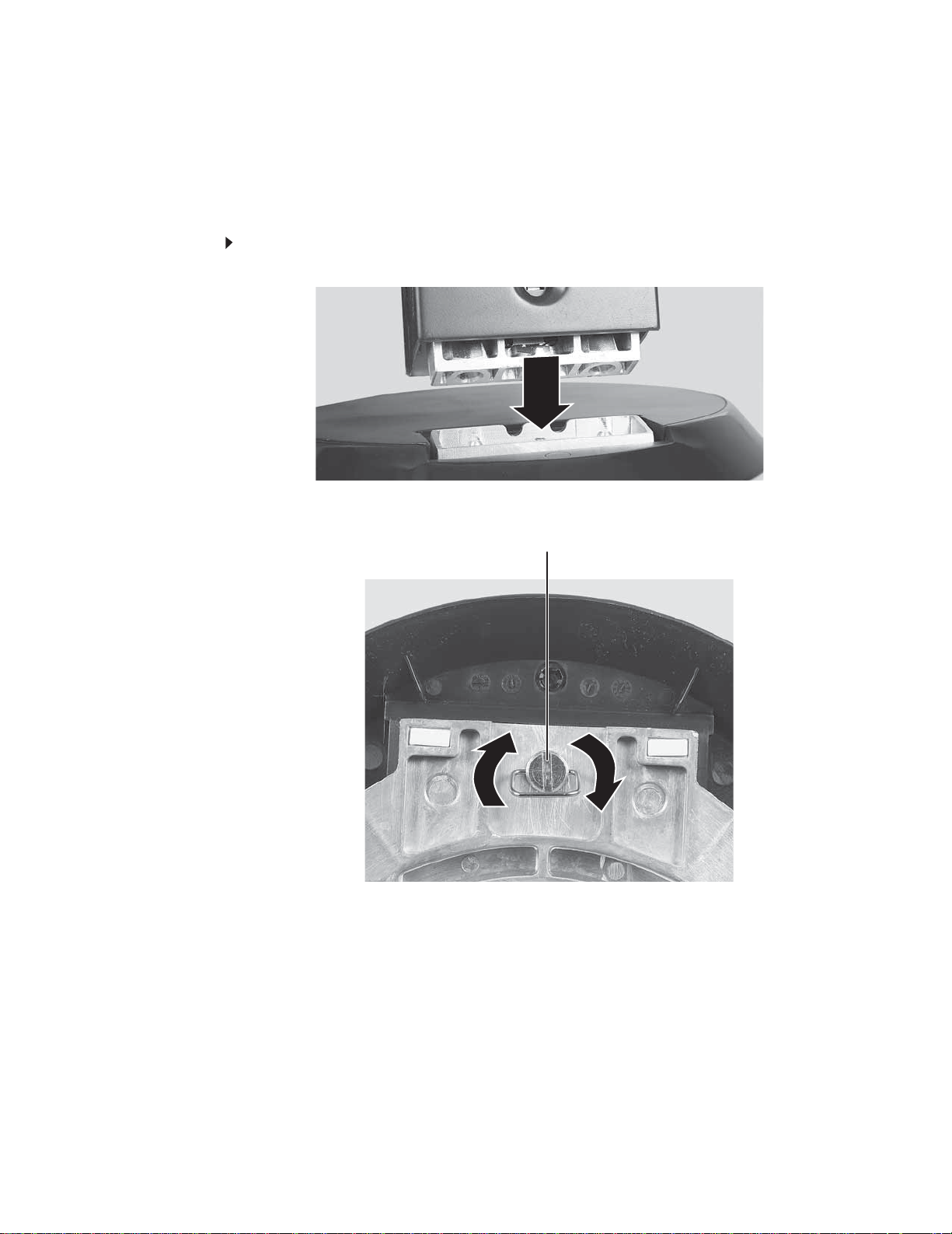
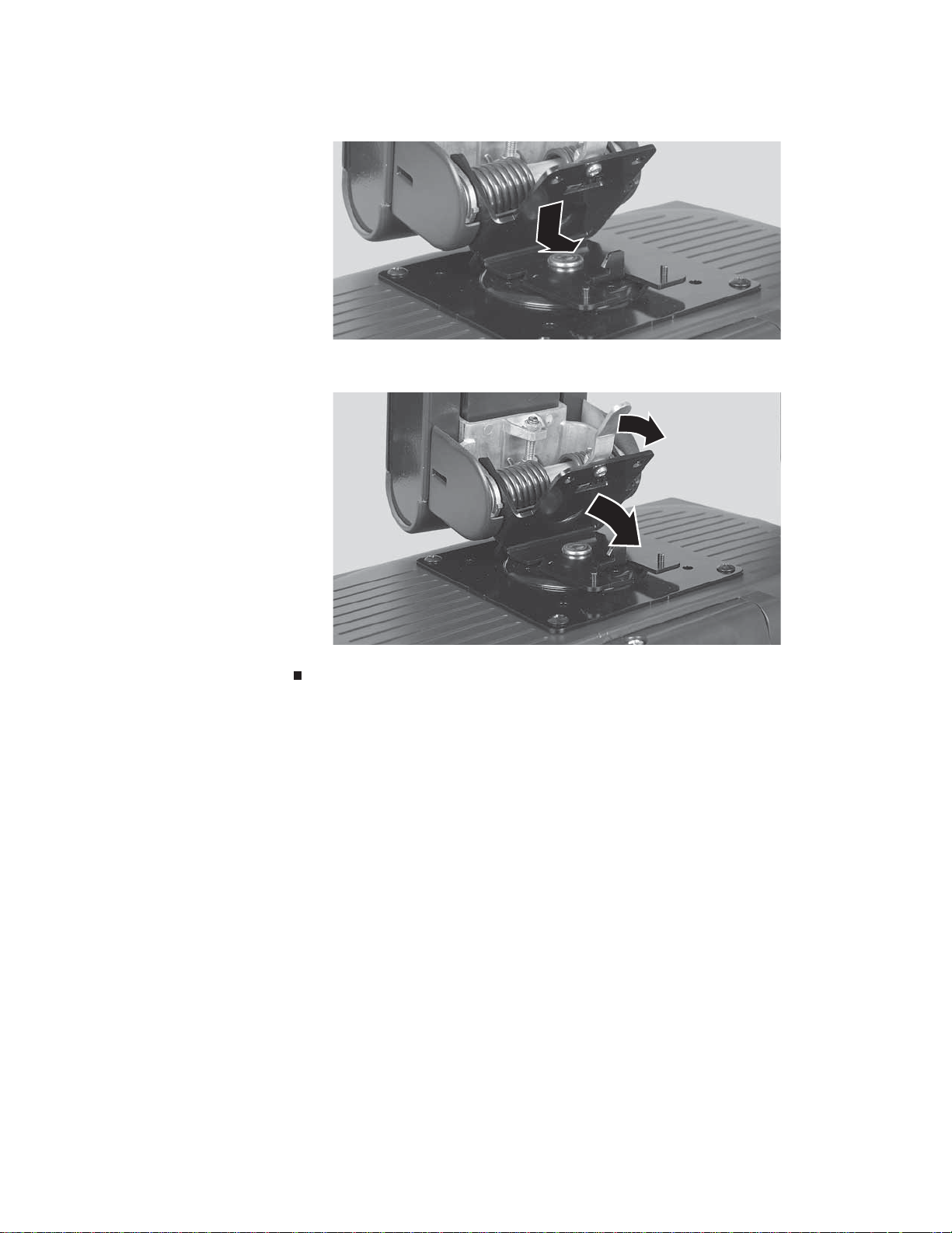
4 Slide the neck’s bracket slots onto the bracket’s mounting tabs.
5 Press the bracket lever to the right and hold it, then lower the neck into place and release
the lever.
6 Test the bracket connection to make sure it is secure, then move the monitor upright.
3
Page 8
CHAPTER 1: Using Your Gateway Flat -Panel Monitor
Connec ting video inputs
To connect video sources to your monitor:
Tip
Rotate th e scre en 9 0° to m ake it easi er to c onn ect th e ca ble s.
1 Position your computer and the monitor so you can reach the back of each.
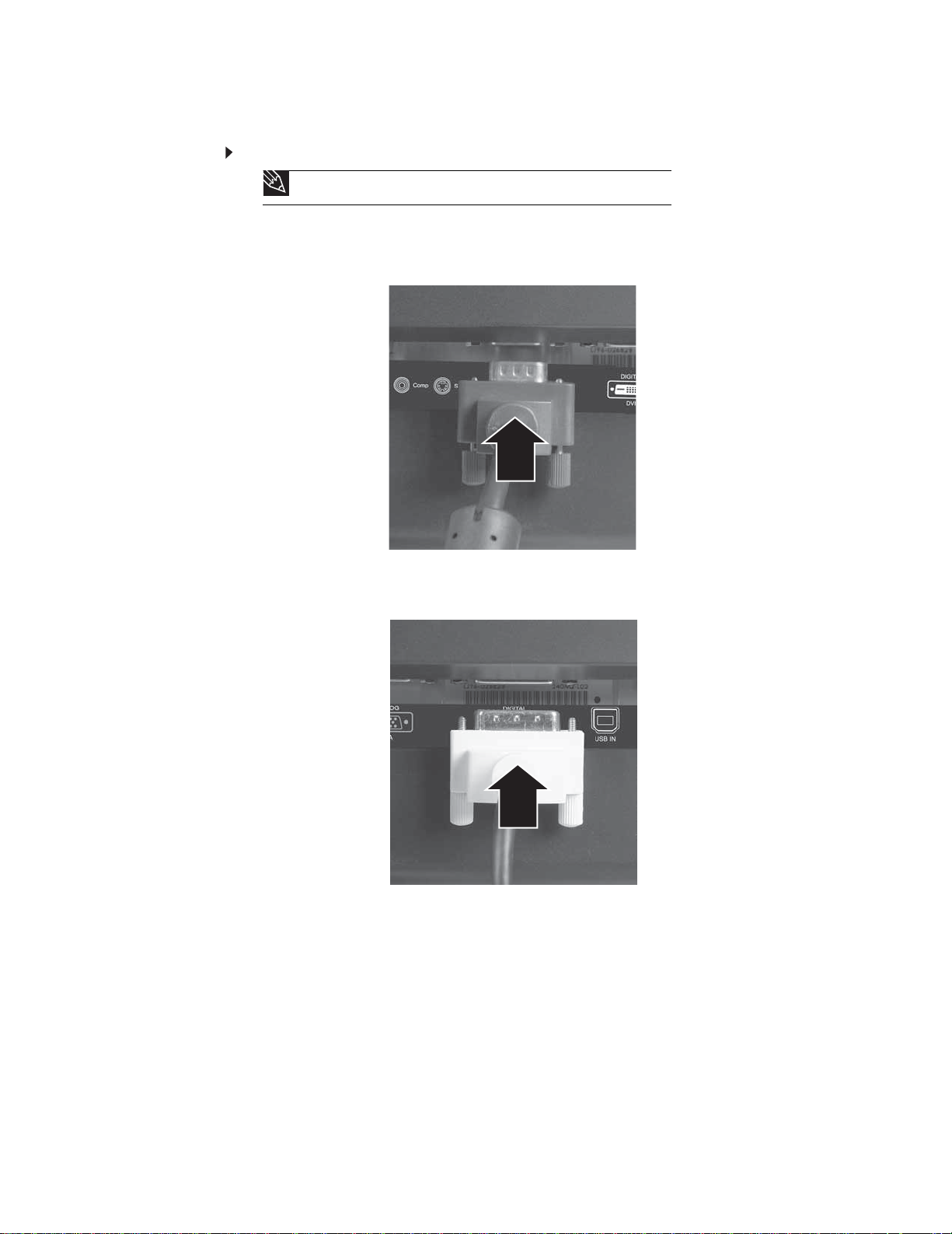
2 Connect the blue VGA video cable to the blue VGA video connector under the back of
the display .
- OR If your computer has a digital video connector (DVI), connect a DVI video cable to the white
connector under the back of the display.
3 Make sure that your computer is turned off, then connect the other end of the video cable
to the matching video port on the back of your computer.
4
Page 9
www.gateway.com
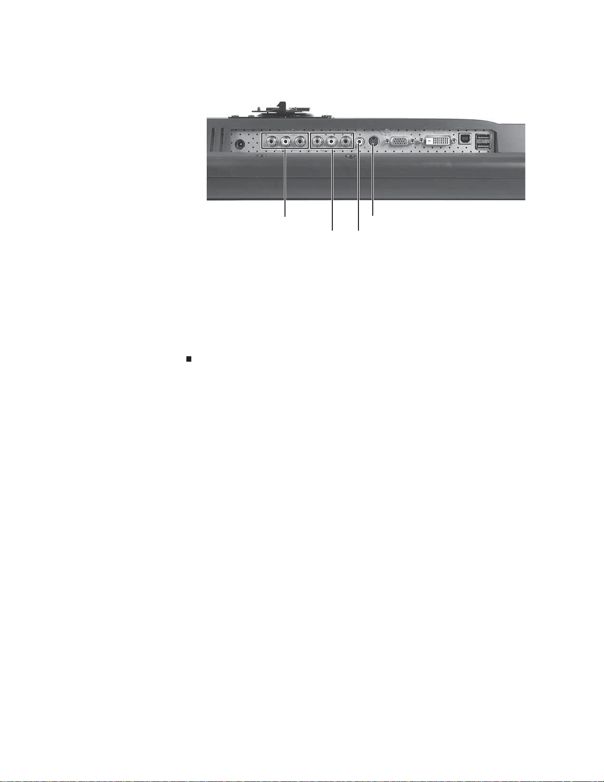
4 Connect other video sources (such as a DVD player, video camera, or receiver) to the
appropriate video jacks on the back of the monitor.
Component video 2 jacks
S-Video jack
Composite video in jackComponent video 1 jacks
• For basic video quality, connect your video device’s composite video in jack to the
corresponding jack on the back of your monitor. (cable not included)
• For better video quality, connect your vi deo device’s S-Video jack to the corresponding
jack on the back of your monitor. (cable not included)
• For best video quality, connect your video device’s component video (green Y,
blue Pb, and red Pr) jacks to the corresponding jacks on the back of your monitor.
(cables not included)
5 Route the cables through the cable clip on the back of the stand. If you plan on using the
screen in portrait mode, make sure you leave enough slack in the ca bles for the screen
rotation.
5
Page 10
Connec ting USB cables
Your monitor has a built-in, four-port USB 2.0 hub that lets you conveniently connect USB devices.
Because your computer cas e may be under your desk or inside a cabinet, these monitor-mount ed
USB ports can be much easier to access.
T o use t he monitor’ s USB ports, y ou must f irst connect the monit or t o a USB por t on y our computer.
Because the USB hub uses power from the monitor, it does not require its own power connection.
To connect USB cables:
is connected to a USB 1.1 port on your computer or on a USB hub.
you want to keep connected most of the time, such as a keyboard, a mouse, or a
printer. Use the USB 2.0 ports on the side of the monitor for connecting USB devices
that are frequently disconnected, such as cameras, flash drives, and USB hard drives.
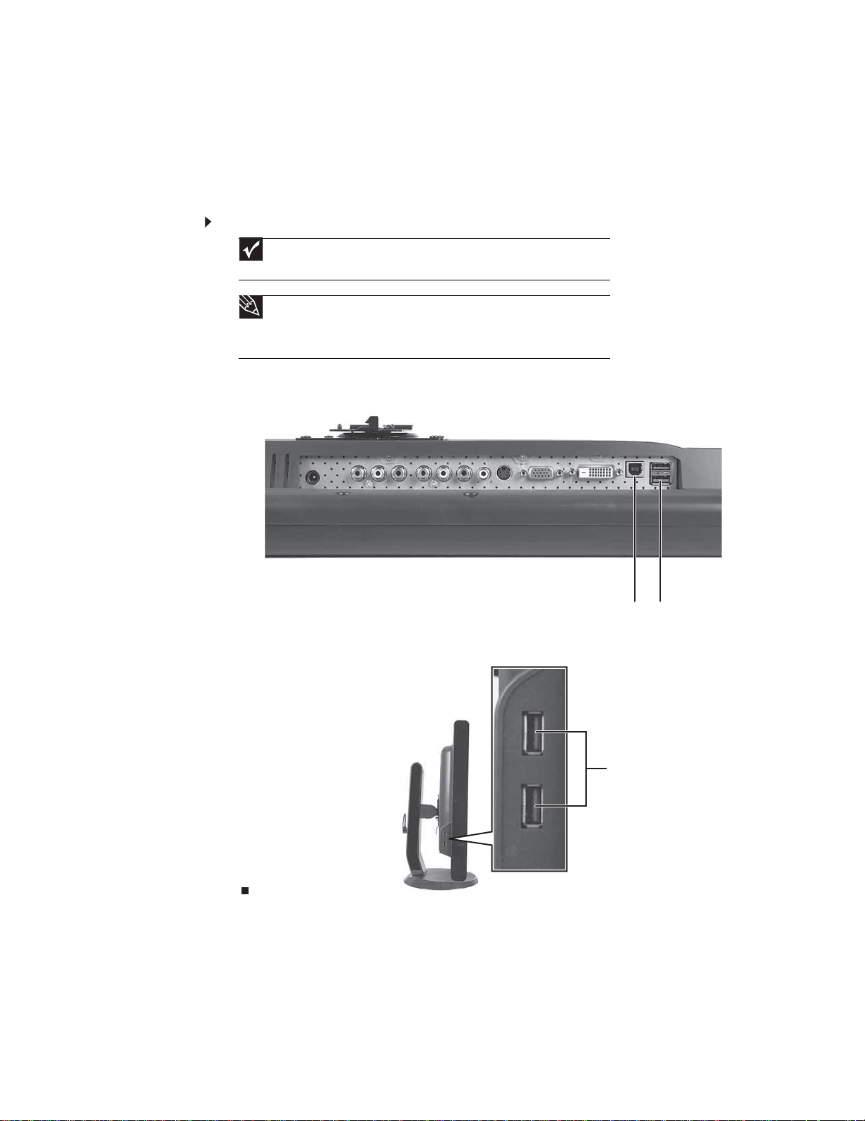
1 Connect the included USB cable to the USB in (“B” type) port on the back of your monitor,
then connect the other end of the cable to a USB 2.0 port on your computer.
CHAPTER 1: Using Your Gateway Flat -Panel Monitor
Important
The built-in USB 2. 0 hub pro vides only low-speed connecti ons if its USB in port
Tip
Use the USB 2.0 ports on the back of the monitor for connecting USB devices
USB in (“B” type) port USB ports
2 Connect any USB device to one of the available USB 2.0 ports on the left side or back of the
monitor.
USB por ts
6
Page 11
Connec ting pow er
To connect power:
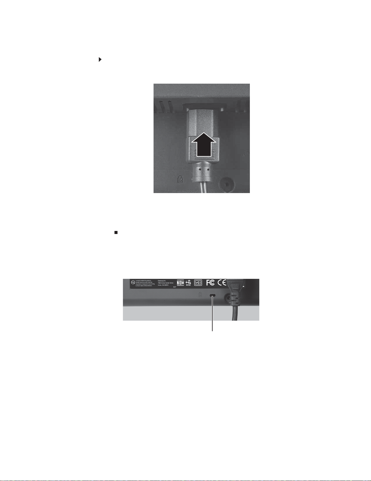
1 Position y our monitor so you can reach the back, then connect the pow er cord to the power
2 Plug the power cord into a correctly grounded power outlet. We recommend using a surge
3 To make sure that the monitor’s power is correctly connected, check the power button on
www.gateway.com
connector under the back of the monitor.
protector to protect your monitor from voltage spikes.
the front button panel. The power icon on the power button should be glowing purple. If
the power icon is not visible, power is not connected.
Connec ting a sec urity c able
Y ou can sec ure y our monit or t o y our computer de sk (or t o another hea vy objec t) with a cable lock.
To connect a cable lock, follow the cable lock’s instructions to connect it to the Kensington lock
slot on the back of your monitor (cable lock not included).
Kensington lock slot
7
Page 12
CHAPTER 1: Using Your Gateway Flat -Panel Monitor
Adjusting th e stand
Rotating the s creen
Tip
To r otate t he screen while the optional speaker bar is at tached, first tilt the scr een back
for more clearance between the speaker bar and the tabletop.
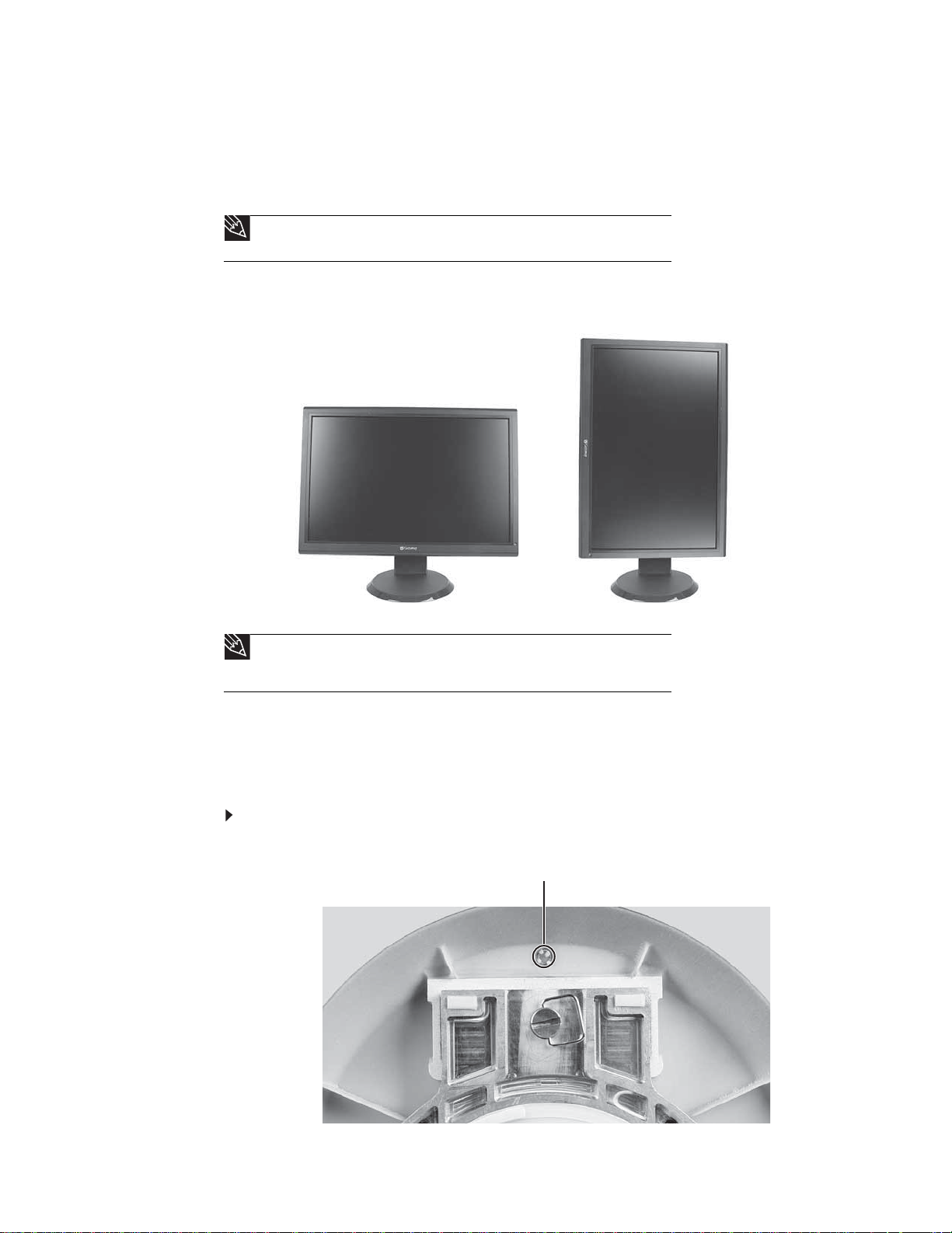
You can rotate the screen clockwise 90° to change between landscape and portrait views. For
information on automatically rotating the display image as you manually rotate the monitor, see
“Using landscape and portrait modes” on page21.
Tip
For the brightest viewing angle, adjust the screen so that you are viewing it from
within a 160° angle of the screen. When the display is rotated to portrait mode, the
side-to-side viewing angle may be reduced.
Adjusting monit or height t ension
The stand is factory adjusted to maintain the height for your monitor. However, if it does not stay
in place when you let go, you need to change the stand’s height tension. You also need to adjust
the stand if the amounts of force required to raise and lower the monitor are not equal.
To adjust your monitor’s height tension:
1 Press the screwdriver access h ole ca p from be low the b ase to remove it from the base.
Portrait modeLandscape mode
Screwdriver access cap
8
Page 13
www.gateway.com
2 Insert a Phillips scr ewdriver through the access hole in the ba s e and onto the height tension
screw (on the back of the stand, in the slot above the USB In port).
Height tension screw
3 Adjust the height tension scr ew so t he monitor sta ys in place when you let go. If the monitor
lowers by itself when you let go, turn the screw clockwise several complete turns. If the
monitor rise s wh en you le t go, turn th e sc re w count er-clockwise se v eral comple t e tur ns. You
may need to tu rn the screw several ti mes before the tension is co rrect for your size of
monitor.
4 Adjust the height tension screw so the raising and lowering f or ces are equal. Aft er the f orces
are equalized, turn the tension screw clockwise two to four turns to slightly decrease the
lifti ng ten si on.
5 For optimum viewing, adjust the height so the top of the monitor is about 1inch (2.5cm)
below eye level.
Adjusting monit or tilt tension
To adjust your monitor’s tilt tension:
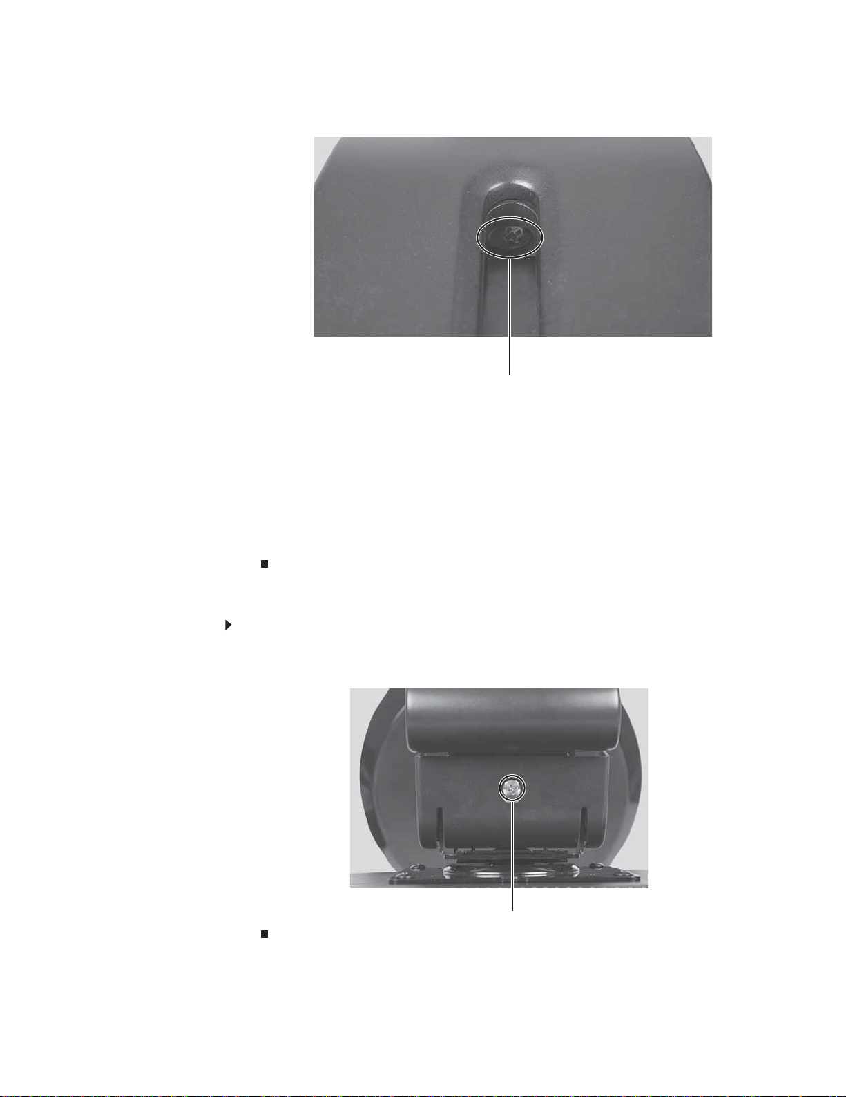
• Adjust the tilt tension screw (on the top of the stand) so the monitor stays in place when
you let go. If the monitor chan ges its ti lt angl e when you let go, turn the screw clockwise
one com pl ete t urn to i ncr ease the ten si on.
Tilt tension screw
9
Page 14

CHAPTER 1: Using Your Gateway Flat -Panel Monitor
Ergonomic guidelines
The recommended screen positioning is based upon the following guildelines. These guidelines
are based on available scientific literature and published standards.
Screen heig ht
The recommended screen height for displays (except in special circumstances, such as for bifocal
use) is that the top of the display should be set at or slightly below (about 1 inch or 25mm) your
eye level while you are sitting in a comfortable working posture. This guideline places the center
of the screen at an ideal 15° to 20° viewing angle for most desktop displays. If the display has
multiple users, the screen height should be easily adjustable to accommodate each user’s height
and preference.
Screen tilt
The screen should be tilted so your line of sight is perpendicular to the screen. This angle creates
the m ost co ns iste nt viewi ng di st anc e w hen sc an nin g fro m th e to p of t he scree n to th e bo ttom .
You may need to adjust lighting to avoid screen glare when the screen is tilted upward.
Screen distance from user
The screen should first be placed at arm’s length from the user, then adjusted back and forth to
suit individual preference.
10
Page 15

www.gateway.com
Setting up the optional speaker bar
An optional speaker bar is available for mounting underneath your monitor. The speaker bar has
touch controls and excellent sound. You can order a speaker bar from www.gateway.com
.
Adjustment slider Mute button
Mode (volume, treble, bass) button
Input (PC or Aux) button
Mounting tab Mounting tab
Kensington lock
slot
3D sound mode button
Power b u tton
Left and right auxiliary input
jacks
Power plug (connects to
power jack in monitor)
Headphone jack
Headphone plug (green)
Microphone plug (pink)
Microphone jack
Headphone jack
11
Page 16
CHAPTER 1: Using Your Gateway Flat -Panel Monitor
To install the speaker bar:
Tip
For easier installation, first rotate the monitor into portrait mode so you can
inst all th e sp ea ker ba r fro m th e s id e.
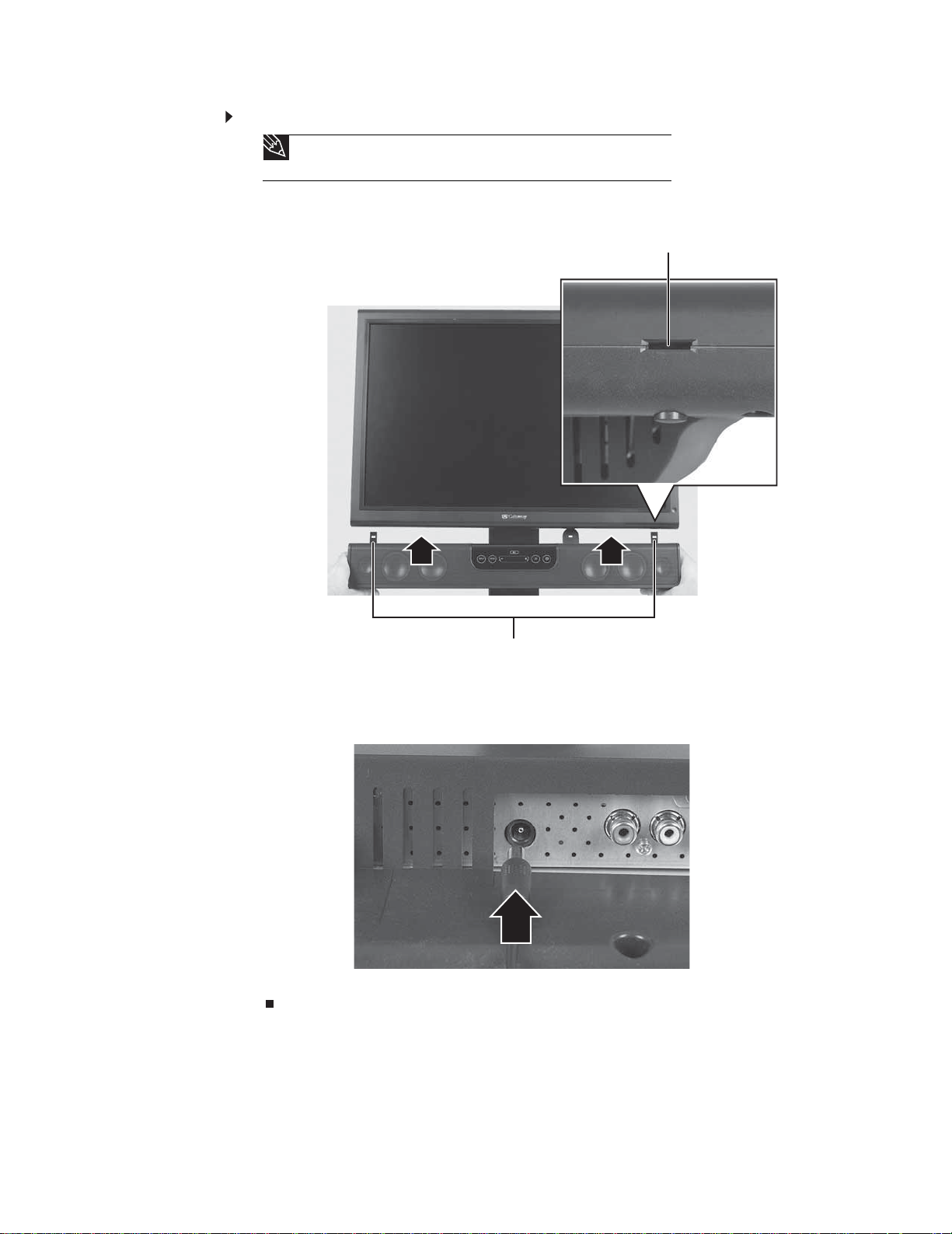
1 Tilt the screen back, then match the tabs on each side of the speaker bar with the slots
underneath the monitor.
Mounting slot
Mounting tabs
2 Sli de the spe ake r b ar onto th e b otto m of th e m on itor u nti l i t s nap s i nto p la ce. Ma ke su re
that it is secure by pulling it downward.
3 Plug the speaker bar’s power plug into the power connector underneath the monitor, then
connect the speaker bar’s headphone and microphone cables to your computer.
For information on using the speaker bar, see “Using the speaker bar” on page23.
12
Page 17

To remove the speaker bar:
1 Disconnect all audio and power cables from the speaker bar.
2 Press the two release buttons on the back of your monitor, then pull the spea ker bar down.
Release button
Starting the monit or
www.gateway.com
Using the E zT ouc h menu butt ons
This monitor features an on-screen display (OSD) and EzTouch menu buttons that let you turn the
monitor on and off, and adjust contrast, brightness, and other settings. For more information on
EzTouch buttons, see “Using the EzTouch menu buttons” on page 14.
T urning on the monit or
To s t a rt t h e m o n i to r :
1 Press the power button on the front of monitor . The power LED on the power button changes
from purple (off) to blue (on).
2 Turn on your computer. After your computer is running, the power LED on the monitor’s
power button should be blue. Allow about 10seconds for the display image to appear. If
the power LED is not blue or you do not see a display image, check the connections. For
more troubleshooting information, see “Troubleshooting” on page24.
3 Adjust the tilt of the monitor for the best viewing angle.
4 After you s ee the Windows de sktop, pre ss the (Menu) button on the front of y our monitor ,
then press (Auto) to automatically adjust your display image to the ideal settings.
13
Page 18

CHAPTER 1: Using Your Gateway Flat -Panel Monitor
5 To mute the volume of the sounds accompanying button presses, press the (Menu)
button on the front of your monitor, p ress (Main Menu), press (Advanced), press
(Audio Feedback), then press the l ower (Adjust) buttons until the volume bar is at
the bottom of the scale.
6 Use the on-screen display (OSD) to adjust other monitor settings. For more information, see
“Adjusting monitor settings” on page14.
Adjusting monit or set tings
Use the monitor controls (locat ed on the monit or itself) and computer control s (acces sible through
Windows) to adjust the display image. For more information about computer controls, see
“Changing Windows screen settings” on page 20.
Using the E zT ouc h menu butt ons
This monitor features an on-screen display (OSD) and EzTouch menu buttons that let you adjust
contrast, brightness, and other settings for the monitor. The monitor saves changes you make to
the settings, even if you turn off the monitor.
Your monitor has two levels of menus, and the functionality of the touch buttons depends on the
menu that is currently open:
• The shortcut menu lets you quickly change some of the most commonly accessed settings.
• The main menu lets you precisely adjust all levels of settings .
14
Page 19

Using the sh ort cut menu
To use the shortcut menu:
1 Press the (Menu) b u tton on the fro nt o f yo u r m on ito r. The res t o f t he b u tton i c on s l ig h t
up and the shortcut menu opens.
Important
The buttons are very sensitive, and may be “pressed” by holding your finger
just above its surface. To completely “release” a touch button, make sure that you
lift your finger well away from the button.
2 To use an EzTouch menu button, lightly touch its icon. For adjusting a setting’s values, you
can press and hold touch buttons as you would conventional buttons.
www.gateway.com
Theme Select
Input Select
Auto
PIP On
PIP Settings
Cancel
Main Menu
• Press the ( Theme Select) buttons to cycle through the preset video themes (brightness,
contrast, and temperature configurations):
• User
• Movie
• Game
• Picture
• Web
• Warm
• Cool
• Press (Input Select) to cycle through the available video sources.
• Press (Auto) to autom at ica lly ad jus t yo ur di spl ay i ma ge to th e i de al setti ng s.
• Press (PIP On) to turn on Picture-in-Picture , and pre s s (PIP Settings) to adjust the PIP
position, size, and other advanced PIP settings.
• Press (Cancel) to ex it the sho rtcut me nu.
• Press (Main Menu) to open the main menu.
• To turn off the button icons and close the menu, wait about ten seconds without pressing
a bu tton.
15
Page 20

Using the main menu
To use the main menu:
1 Press the (Menu) b u tton on the fro nt o f yo u r m on ito r. The res t o f t he b u tton i c on s l ig h t
up and the shortcut menu opens.
holding your finger just above its surface. To completely “release” a touch button,
make s ure th a t you li ft yo ur fi ng er we ll away from the bu tton.
2 To use a button, lightly touch its icon. For adjusting a setting’s values, you can press and
hold touch buttons as you would conventional buttons.
3 Press (Main Menu) . The main menu open s.
CHAPTER 1: Using Your Gateway Flat -Panel Monitor
Important
The EzTouch menu buttons are very sensitive, and may be “pressed” by
Choose option or mode, Adjust
setting
Select
Back
Menu or Menu Off
Tip
While the OSD is active, on-screen labels appear next to the buttons to help
you identify them.
4 Press the ( Choose Option) buttons to highlight a setting, the n press (Select) to open
the selected menu or setting.
5 Press the (Adjust) b utto ns to a dju st the sett ing or cha ng e th e opti on .
6 Press (Back) to return to a previous menu.
7 When you have finished making all adjustments, press (Menu Off) to exit.
16
Page 21
OSD Menu Description
www.gateway.com
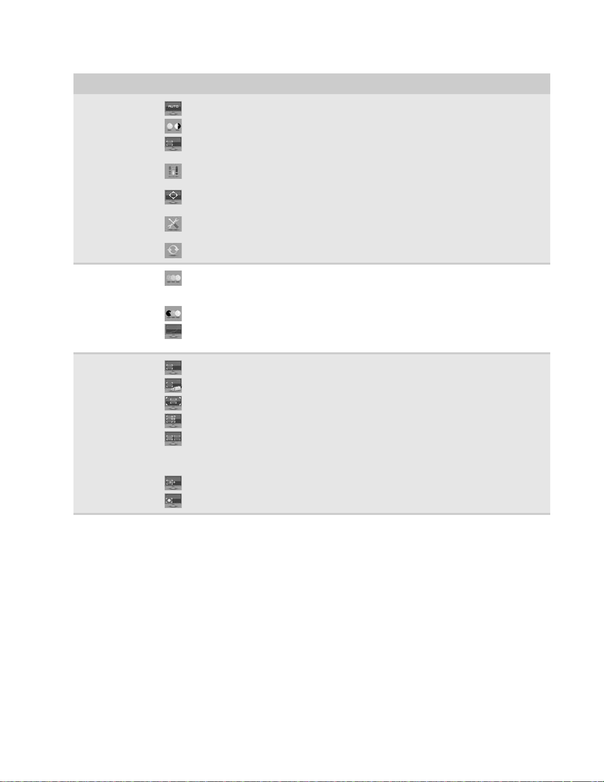
Main menu
Pictur e menu
PIP Settings menu
Auto—Automatically adjusts your monitor to its optimum settings. (VGA input only)
Picture—Opens the Picture menu, where you can adjust brightness, contrast, and gamma.
PIP—Opens the PIP Set ting s menu , wh er e y ou can adjus t the s our ce, position, si ze, and tr ansp are ncy
of the Picture-in-Picture image.
Video a dju st—Opens the Video Adjust menu, where you can adjust the RGB (red, green, and blue)
values of the video image from a source such as composite video, S-Video, or component video.
Geometry—Opens the Geometry menu, where you can adjust image size and minimize distortions.
(VGA input only)
Advanced—Opens the Advanced menu, where you can adjust color balance, change the OSD
language, and display information about current monitor settings.
Reset— Resets the mon itor to i ts factor y setti ngs for th e curren tly di spl ayed inpu t.
Brightness—Adjusts the amount of light in the darkest portion of the picture. Use the lowest
brightness setting you are comfortable with to maximize the life of the monitor backlights. You may need
to readjust brightness after the monitor warms up.
Contrast—Adjusts the level of white between the lightest and darkest portions of an image.
Gamma—Customizes the gamma level. High gamma levels increase white levels and low gamma
levels increase contrast.
PIP Display—Toggles the display of the PIP window.
Source—Sets the source of the video used in the PIP window.
Posi tio n—Sets the position of the PIP window on the main screen.
Size—Sets the size of the PIP window.
Transparency—Sets the transparency of the PIP window. The PIP window can be from almost
transparent to completely opaque. When the PIP window is transparent, you are able to see through the
PIP video dis play to y our W in do w s d esk t op , w hic h m ak e s it eas ier to access y our c omput e r pr ogr ams wh ile
watching video.
Swap—Switches the PI P im age to the ma in im age, a nd the main ima ge to th e PIP i mag e.
PIP Picture—Opens a menu wher e you can set the PIP bright ness, contra s t , saturation, and tin t /hue.
17
Page 22

OSD Menu Description
CHAPTER 1: Using Your Gateway Flat -Panel Monitor
Video Adjust me nu
Unless otherwise i ndi cated, these settings a pply only to SD ( stan da rd defin iti on) video at 480 i an d bel ow.
Where “PC input” is indicated, the resolutions that apply are from 800 × 600 to 1920× 1200.
Sharpness—Adj usts sharpne ss for video images.
Video Scaling—Sets video as pect ratio s and s caling be tween W ide , Zoom, 1 :1, and Panoramic m odes.
PCinput: sets resolution aspect ratios and scaling between Wide, Zoom, and 1:1.
Wide mode stretches a standard broad cast o r full -frame imag e to fill th e
entire screen. Widescreen ( 1.7 6: 1) images fill the entire screen without distortion,
while wides creen ( 1.85:1 and 2.35:1) image s app ear w ithout distortio n but w ith
black bars at the top and bottom. PC in put: Stretches the image to fit the entire
screen.
Zoom mode crops off a portion of a widescreen image in order to fill the
entire screen with a distortion-free and black bar-free image. PCin put: Zooms
the ima ge to fil l th e s creen from top to b ottom wi th b la ck ba rs o n the le ft and
right sides of the image.
1:1 mo d e preserves the movie’s orig inal aspect rat io, so a sta ndard broa dcast
or full-frame movie appears with black bars on the left and right of the image.
PCinput: Preserves the original aspect ratio of the resolution by using black bars on
the left and right sides and variable sizes of black bars on the top and bottom of the
image (depends on resolution).
Panoramic mode uses selective distortion to s tretch a st an dard broadcas t
or full-frame image t o fill t he entir e sc reen . Unlik e Wid e mode , P anor amic mode
stretches only the left and right s ides of the image, and leaves the center of the
image distortion free.
Noise Reduction—Uses noise reduction filters that adapt to the amount
of noise and motion from the video source.
Film Mode Detection—Film Mode Detection detects frame rates of the source image and adapts
the frame rate of the display for ultimate image quality. Bad Edit Detection and Correction corrects
incorrectly synchronized video.
Auto Video Enhance—Enables DCDi, Cross Color Reduction, and MADI for optimized video
performance.
DCDi by Faroudja—Directional Correlation De-interlacing reduces jagged edge artifacts on diagonal lines.
Cross Colo r Re duct io n—Reduces cross-color artifacts, such as unintentional flashing colors or rainbow
patterns, that result from composite video signals.
MADI—Motion-Adaptive De-Inter lac ing ensur es a more static (f lic k er -f ree) displa y ima ge f or image sec tions
not containing moving elements, and ensures smoother edges for moving elements.
18
Page 23

OSD Menu Description
www.gateway.com
Geometry menu
Advanced menu
H Position—Moves the display image left and right. You can also press the Auto button to configure
the vertical and horizontal position automatically.
V Position—Mov e s the display im age up anddown. You can also pres s the Auto button to configure
the vertical and horizontal position automatically.
Clock—Minimizes any vertical bars or stripes visible on the screen background. The horizontal screen
size will also change.
Phase—Minimizes any horizontal distortion and clears or sharpens the displayed characters.
Color—Customizes the color levels.
Language—Changes the la nguage of the OSD.
LED Mode—Chan ge s t he br i ght ness of the S tandby and P ower LED t o Day Mode or Nite Mode. W h en
watching movies in a darkened room, you may want to change the LED mode to Nite Mode to avoid an
over-bright, distracting power LED indicator.
DVI Video mode—Changes the DVI video mode by enabling either RGB Color Space (used for digital
input) and YUV Color Space (used for analog TV input such as NTSC, PAL, and SECAM).
Audio Feedback—Changes the volume of the sounds that accompany button presses. Decrease all
the way down to c omp letely mu te the b utton ton es.
Information—Displays current screen resolution and input source for the main display.
Resolution reminder—If the computer di splay input (VG A and D VI) is not s et t o 1 920× 1200, disp lay s
a reminder that you should change your computer’s settings to use the optimum 1920 × 1200 resolution.
If you prefer using your monitor at a resolution less than 1920×1200, use this option to turn off the
Resolution Reminder. For information on changing your computer’s display resolution, see “Changing
Windows screen settings” on page 20.
Reset Al l—Resets a ll val ues to th e factor y sett ings.
Using Pi cture-in-Pic ture (P IP)
Picture-in-Picture (PIP) is a convenient way to view video from multiple video sources at the same
time. Refer to the following chart to determine which combinations of video sources can be used
as a PIP disp lay.
PIP display
Main display
VGA - OK OK* OK OK
DVI OK - OK OK OK
Component (Y Pb Pr) No OK - OK OK
S-Video OK OK OK - No
Composite OK OK OK No -
* Only 480i component (Y Pb Pr) video can be used with VGA as a PIP . With this combination, the Swap feature is not available. To
switch t o full-scr een component video w hen 480i content is us ed as a PIP, press the Input button on the side of the monitor.
If a 480p source is input to the YPb Pr jacks and Y Pb Pr is a PIP display within a VG A main display , then the P IP image will be distorted.
Change the output of your ext ern al YPb Pr device to 480i if P IP is required w ith VG A t o eliminate t he PIP dist ortion. For more
information, see your Y PbPr device’s user guide.
** For some video resolutions, refresh r ates, a nd video scaling modes, PIP may not be allowed. If y ou receiv e a mess age that PIP is not
available , try the follo wing:
■
Adjust the refresh rat e in Window s to 60 Hz. See Window s online Help for more inf ormation.
VGA** DVI** Component (Y Pb Pr ) S-Video Composite
19
Page 24

CHAPTER 1: Using Your Gateway Flat -Panel Monitor
■
Adjust the video scaling mode to Wide on the monitor.
■
Change the resolution of t he Windows de sktop t o matc h the monitor’s f ull reso lution of 1 920 × 1200. For more information see
“Changing color depth and screen resolution” on page 20.
Changing W indow s sc reen set tings
Adjusting the color depth and screen area ar e two of t he most basic display set ting s you ma y need
to change. You can also adjust settings such as the screen background and screen saver.
Changing color dept h and sc reen re solution
Color depth and screen resolution are two of the most basic monitor settings you may need to
change to suit your needs.
Color depth is the number of colors your computer uses to display images on your monitor. Most
images look best displayed with the maximum number of colors available. If the color in your
images seems “false” or “jump y,” especially af t er y ou ha v e pla yed a game or run a video-intensive
program, check the color depth setting and return it to the highest color setting, if necessary.
Screen resol uti on is the number of pixels (individual colored dots) your computer uses to display
images on your monitor. The higher the resol ution, the more information and screen components
(such as icons and menu bars) can be displayed on the monitor.
Help
For more information about adjusting the screen, click Start, then click Help and
Support. Type adjusting monito r settings in the Search Help box, then press E
NTER.
EzT une s oftw are
When installed onto your computer, EzTune™ software lets you control many of the monitor
settings from your computer. With EzTune, you can:
To change the color depth or screen resolution:
1 Click (Start), Control Panel, then under Appearance and Personalizati on, cli ck Adjust
Screen Resolution. The Display Settings dialog box opens.
2 To change the color depth, click the Colors list, then click the color depth you want.
• Low (8-bit) = 256 colors
• Medium (16-bit) = 65,500 colors
• Highest (32-bit) = 16,700,000 colors
3 To change the screen resolution, drag the Resolution slider to the size you prefer.
4 Click Apply. If the new set tings do not look right, click No. If the new settings make the scr een
illegible and you cannot click No, the sett in gs ret urn to t hei r p revio us valu es afte r seve ra l
seconds.
5 Click OK, then click Yes to save you r ch an ges .
• Change the orientation of the image (landscape to portrait) by just rotating the screen
(requires the optional height-adjustable stand available in the U.S. at www.gateway.com
)
• Change brightness, contrast, and color balance
• Change screen geometry
• Set the display position and resolution
20
Page 25

www.gateway.com
For more information, see the program’s CD or the installed program’s online help.
Using land scape and por trait modes
EzTune automatically switches the display to the appropriate mode (landscape or portrait) when
you rotate the screen. This feature works only with VGA or DVI input (the OSD itself does not rotate
into portrait mode) .
While using po rtrait mod e:
• Full-screen video may display incorrectly or be slow.
• Video games or other full-screen applications may not be fully compatible.
• Some programs are not able to recognize and adapt to your monitor’s por trait mode. If you
experience problems with a program while using portrait mode, switch to landscape mode
and restart the program.
21
Page 26

Video mo des
CHAPTER 1: Using Your Gateway Flat -Panel Monitor
Your monitor supports several video modes. If you do not use the best mode for the monitor, the
display image may look s lightly “ fuzzy.”
Mode Resolution Horizontal
freq uen cy ( kHz )
1 720 × 400 31.469 70 N
2 640 × 480 31.469 60 Y
3 640 × 480 37.9 72 N
4 640 × 480 37.5 75 N
5 800 × 600 35. 1 56 N
6 800 × 600 37.879 60 Y
7 800 × 600 48.1 72 N
8 800 × 600 46.875 75 N
9 1024 × 768 48.363 60 Y
10 1024 × 76 8 56 .5 70 N
11 1024 × 768 60.123 75 N
12 1152 × 864 67.5 75 N
13 1280 × 1024 64 60 Y
14 128 0 × 1 024 8 0 75 N
Vertical
frequency (Hz)
Available in DVI
mode
15 1400 × 1050 65.317 60 Y
16 1400 × 1050 82.278 75 N
17 1440 × 900 55.935 60 Y
18 1440 × 9 00 70.635 75 N
19 1680 × 1050 65.29 60 Y
20 1680 × 1050 74. 9 75 N
21 1920 × 1200 74 60 Y
22 1920 × 1200 74. 6 60 N
22
Page 27

Using t he speak er bar
To turn on the speaker bar:
• Press the power button on the speaker bar. The speaker bar turns on, and the button LEDs
turn on.
To use headphones :
Tip
You can connect a pair of headphones to each headphone jack.
• Plug headphones into either of the speaker bar’ s headphone jacks. The speaker bar’s volume
is muted, and sound is played through the connected headphones. You can connect
headphones to each headphone jack, and sound will play out of both sets.
www.gateway.com
Changing speaker bar settings
You can change the following settin gs on the optiona l speaker ba r:
• Volume
• Treble
• Bass
• Mute
• Input
• 3D sound
To a d j u st t h e vo l um e :
1 On the speaker bar , pr ess MODE until VOLUME is selected (VOLUME is the default se lection).
The current mode is displayed under the MODE button.
2 Press + or – on the adjustment slider to adjust the sound in single-step increments, or slide
your finger alon g th e slider for larger increments. Slide to t he r ight to increa s e v olume, slide
to the left to decrease volume. Press and hold + or – to auto rep eat .
3 To mute or unmute the sound, press the mute button.
To adjust the treble and bass :
1 On the speaker bar, press MODE until TREB or BASS is se lected.
2 Press + or - on the adjustment slider to adjust the sound in single-step increments, or slide
your finger along the slider for larger increments. Slide to the right to increase, slide to the
left to d ecrea se.
To change the audio input source:
• On the speaker bar, press INPUT to sele ct PC (PC is the default selection) , AUX, or both.
To enable 3D sound:
• On the speaker bar, press 3D. The speaker bar plays Surround Sound-like audio.
23
Page 28

CHAPTER 1: Using Your Gateway Flat -Panel Monitor
P ower man agement
Energy declar ation
When connected to a computer that supports the VESA Display Power Management Signaling
(DPMS) Protocol, the monitor can conserve significant energy by reducing power consumption
during periods of non-use. When your computer goes into the energy saving mode, the monitor
will then enter the Active Off mode (sleep) . In the Active Off mode the Power LED will still show
orange.
Use these conventions and the power can be reduced to the following levels:
VESA St ate LED Indicator Power Consumption
On Blue <75W
Standby Orange <5 W
Off Purple ≤ 2W
To “wake” the monitor when it is in Standby/Active Off mode, move the mouse or press any
keyb oa rd key.
You can change the monitor’s power management settings using the Windows Control Panel.
To access the monitor’s power management options:
1 Click Start, then cl ick Control Panel. The C ontrol P anel window opens. If your Contr ol Panel
is in Category View, click Performance and Maintenance.
2 Click/Double-click Power O pti ons. The Power Options Properties dialog box opens.
3 Click Turn o ff mo n it o r to ope n th e l is t o f va lu es for thi s s etti ng , th en cli ck t he a mo un t o f
time you want to wait for the monitor to change to Standby mode.
4 Click OK. Your settings are saved, and the dialog box closes.
Maintaining
To keep the monitor in optimal working order:
• Do not block the ventilation holes.
• Do n ot exp ose the mo ni tor to ra in or u se nea r wa ter.
• Keep th e m on ito r away fro m ra dia tor s o r h ea t ve nt s.
• Keep the monitor out of direct sunlight.
Caution
Do not use any type of abrasive pad or glass cleaner. You will permanently
scratch the screen.
• To clean the monitor, use a soft cloth slightly moistened with water only. Wipe the cabinet,
screen, and controls.
Troubleshooting
Important
Make sure that the monitor has warmed up for approximately 30 minutes before
making any judgments about the picture quality.
24
Page 29

No power
No picture
www.gateway.com
If you have problems with the monitor, the information in this troubleshooting section may help
you solve them.
Make sure that the power cord is connected correctly to both the back of the monitor and the
wall outle t. For more inf o r m ation about connecting t h e power cord, see “Connecting the monitor”
on page 2.
• Press (Menu), then (Input Select) to make sure that you have selected the correct
video source.
• Make sure that the power cord is connected correctly to both the back of the monitor and
the wall outle t. F or mor e information ab out conne c ting th e po w er cor d, see “Connec ting the
monitor” on page 2.
• Make s ure th at th e v ide o c ab le i s c on necte d se cure ly to th e ba ck o f th e m on ito r an d
computer. For more information about connecting the video cable, see “Connecting the
monitor” on page 2.
• Make s ure th at the mo nito r i s t urn ed on .
• If the power LED is oran ge:
• Make sure that your computer is turned on.
• Move the mouse or press any key on the keyboard to bring the monitor out of sleep
mode.
• Restart your computer with the monitor turned on.
• Make sure that the video cable is not damaged.
• Check the end of the video cable for any pins that might be bent or pushed in.
• Turn off the monitor and unplug the video cable from the back of your computer. Turn the
moni tor ba ck o n a nd wai t for ten sec on ds. If th e m oni tor is fun cti on ing co rre ctly, a “No
Signal” message appears. For more information about connecting the video cable, see
“Connecting the monitor” on page 2.
Display colors ar e wrong
• Press (Menu), then (Auto) to automatically adjust the display image to the
ideal settings.
• Restart your computer with the monitor turned on.
• Make sure that the video cable is connected securely to the back of the monitor and your
computer. For more information about connecting the video cable, see “Connecting the
monitor” on page 2.
• Make sure that the video cable is not damaged.
• Check the end of the video cable for any pins that might be bent or pushed in.
Pic ture has shado ws or “ gho sts”
• Press (Menu), then (Auto) to automatically adjust the display image to the
ideal settings.
• Remove any exten sion cab les o r switchb oxes.
• Make sure that the video cable is connected securely to the back of the monitor and your
computer. For more information about connecting the video cable, see “Connecting the
monitor” on page 2.
• Make sure that the video cable is not damaged.
• Check the end of the video cable for any pins that might be bent or pushed in.
• Make sure that your monit or connection is using the VGA cable that came with y our monitor.
25
Page 30

CHAPTER 1: Using Your Gateway Flat -Panel Monitor
Color is not unif or m
• Press (Menu), then (Auto) to auto ma tic al ly adj ust th e di sp lay i ma ge to th e
ideal settings.
• Make sure that the monitor w arms up for at lea st 30minutes before making a final judgment
about color uniformity or brightness.
Image is not siz ed or cent ered correc tly
• Press (Menu), then (Auto) to auto ma tic al ly adj ust th e di sp lay i ma ge to th e
ideal settings.
• Use the position controls to adjust the image. For instructions on how to adjust the display
image positio n, see “Adjusting monitor settings” on page 14.
The monit or has pi xels that are alw a ys dark or t oo bright
• This condition is normal and inherent in the TFT technology used in active-matrix LCD
screens. Gateway’s inspection standards keep these to a minimum. If you feel these pixels
are unacceptably numerous or dense on your display, contact Gateway Customer Care to
identify whether a repair or replacement is justified based on the number of pixels affected.
Speake r bar does not work
I installed the speaker bar, but no sound is coming out of the speakers.
• Make sure that the speaker bar power cord is plugged into the power connector on the back
of your monitor, and that the monitor is plugged into an ACpower outlet.
• Make sure that the speaker bar’s headphone plug (green) is plugged into the headphone
jack on your computer.
• Make sure that the speaker bar is turned on and that the volume is turned up.
• The speaker bar may be using AUX input mode. Press the INPUT button on the speaker bar
until PC is selected, or connect an audio device to the AUX jacks and turn it on.
• Your headphone/speaker jack may have been muted using Windows sound controls. To
check your headphone/speaker mut e settings, c lick the speaker icon in the Windows taskbar ,
or click (Start), Control Panel, Sounds and Audio Devices, the Volume tab, then cli ck
Advanced. For optimum volume control using the speaker bar, we recommend that you
set the Windows volume mid-way between the lowest and highest setting.
I want to plug in my headphones, but there is a headphone jack on both sides of the speaker bar. Which should I use?
• You can use either jack or both jacks at the same time.
I do not get sound from my headphones.
• Make sure that your speaker bar is connected to an audio source by unplugging your
headphones and adjusting the speaker bar volume.
• After y ou make sure that your speak er bar can play sounds, make sur e that y our headphones
are plugged into one of the headphone jacks on the sides of the speaker bar, and not into
the microphon e jack.
The sound comin g from the speakers soun ds distorted.
• Turn down the volume until the distortion disappears.
• Check the audio output volume of the sound device the speaker bar is connected to. If the
audio device’s output volume is set too high, the speaker bar’s sound may always be
distorted. To adjust the audio device’s output volume, see the device’s user guide. To adjust
the volume in W ind ows XP, click the speak er ic on in t he W i ndo w s ta skb ar, or click (Start),
Control Panel, Sounds and Audio Devices, the Volume tab, then click Advanced. For
optimum volume control using the speaker bar, we recommend that you set the Windows
volume mid-way between the lowest and highest setting.
26
Page 31

FAQs
General
www.gateway.com
I plugged my microphone into the speaker bar’s microphone jack, but my computer cannot record any sound.
• Make s ure th at th e sp eake r ba r’s m icro pho ne p lug (pi nk) is co nne cted to the m icro pho ne
jack on your computer.
• Your microphone jack may have been muted using Windows sound controls. To check your
microphone’s mut e settings, c lick the speak er icon in the Window s taskbar , or c lick (Start),
Control Panel, Sounds and Audio Devices, the Volume tab, then click Advanced.
This section contains answers to frequently asked questions.
What is DCDi® by Faroudja?
DCDi® by F aroudja is a vi deo mode algorithm t hat stands f or Direct ional Corr elation De-Inter lacing.
It was initially designed for fast-action video-based material. Its general purpose is to reduce
jagged edges along diagonal lines caused by interpolation. Utilizing this algorithm, DCDi does not
simply weave together two fields of video that match. DCDi creates new information through
interpolation which “smoot hs” t he diagonal edges. DCDi constantly monitors edge transitions and
fills in any of the gaps that need smoothing.
How T o
I have the monitor connected to my notebook’s VGA port and I see no image on the screen.
You have two options:
• If your notebook supports dual displays, you can use both your notebook’s display and
this monitor in extended desktop multi-monitor mode. See Windows Help to learn how
to enable multiple monitors.
• You can also use this monitor as your primary monitor and not use the notebook’s
screen. Notebook computers typically have an FN key combination that lets you toggle
between your notebook’s display and an externally attached display. On Gateway
notebooks, this key combination is F
keys. See your notebook user guide for more information.
N+F4 . The F4 key i s l oca ted al on g th e top row of
Setup
Why does the image looks stretched or fuzzy when I connect the monitor to my computer?
You must a dju st th e ope rat ing system’s disp lay se ttin gs to match th e mo nito r’s o pt ima l (native)
1920× 1200 setting. For information on adjusting settings in WindowsXP, see “Changing color
depth and screen resolution” on page 20.
I do not see 1920 × 1200 available in the Windows display control panel.
• Make sure that your video card can display at 1920× 1200 resolution.
• This may be caused by older video driv ers on your computer. See the Gateway support Web
site (support.gateway.com) for updated video drivers for your computer. You can also go
directly t o y our v ideo card’ s support W eb sit e f or the mo st up-t o-date video dr iv ers. The W eb
sites for the major video card manufacturers are:
ATI®: http://www.ati.com
Intel®: http://www.intel.com
Nvidia®: http://www.nvidia.com
27
Page 32

Technical
CHAPTER 1: Using Your Gateway Flat -Panel Monitor
When I connect the monitor’s USB hub to my computer, I see an error message saying that my USB hub may not be running at full speed.
This can happen if you connected the monitor’s high-speed USB 2.0 hub to a low-speed USB 1.1
hub or a USB 1.1 port on your computer. To use the monitor’s high-speed USB 2.0 capabilities, you
must connect the monitor to a USB 2.0 port on your computer.
When I run my games, I do not see support for widescreen displays. What can I do?
Newer games are adding support f or widesc reen displays as the wides creen f ormat becomes more
popular. Check the game’s Web site for updates. You can also consult the following Web site for
specific settings and options to configure older games to support widescreen:
http://www.widescreengamingforum.com
Some adjustments may require you to make changes to the Windows System Registry. We
recommend making a comp lete system backup before changing the System Registry.
Why do I see “noise” or “trash” on th e screen?
When your display’s digital capabilities exceed a digital broadcast signal, the signal is increased
(up-converted) to match the display capabilities. Up-converting can cause “noise” or “trash.” The
signal on DVI-D is HDCP encoded. Stop and restart the source to allow renegotiation.
What is HDCP and how do I troubleshoot it?
High-bandwidth Digital Content Protection (HDCP) is a specification developed by the Intel®
Corporation to protect digital entertainment content that uses a digital visual interface (DVI).
HDCP encrypts the transmission of digital content (signal) between the video source (computer,
DVD player, or set-top box) and the digital display (monitor, digital television/DTV, or projector).
HDCP is not designed to prevent copying or recording of digital content, but only to protect the
integrity of the content as transmitted.
.
How does HDCP work?
Implementation of HDCP requires a license obtainable from the Digital Content Protection, LLC,
which then issue s a set of unique secret de vice k e ys to all authori zed de vices. Dur ing authentication,
the receiving de vice only accepts content af ter it acknowledges the k ey s. T o further prev ent stealing
of the data or line tapping, the transmitter and receiver generate a shared secret value that is
constan tly checked throu ghout the tran smissi on. After au thenti catio n is est ablis hed, th e
transmitter encrypts the data and sends it to the receiver for decryption.
What happens if I lose signal to the display while watching a movie on a HDCP-equipped component?
The component must be restarted to establish renegotiation.
For example, while watching a movie on a HDCP-enabled DVD player, you change the receiving
device (DTV, monitor, or projector) input to watch broadcast TV , then change the input back to watch
the DVD movie. However, you are unable to watch the movie. This is because when the input was
changed, the receiver lost the HDCP signal. Restart the HDCP-enabled DVD player to allow
renegotiation.
What is the cause if a movie starts and then slowly fades to static?
The receiving device is not HDCP compatible or it is not negotiating correctly. Restart the video
source and re-plug all video cables from the source to the TV.
How do I know if a component is HDCP compliant?
If the video source device does not have a DVI or HDMI connection, it is not HDCP compliant.
28
Page 33

Video/Display
www.gateway.com
When I displa y vi deo f rom S-V ideo , compos it e, or compon ent, wh y do es the v ideo lo ok o ver ly compressed?
See your video device user manual to adjust the video or TV format output to 16:9. S etting this
option to 4:3 results in compressed video. This is done differently on all brands of video devices,
so it is important that you read your video device user guide or the help tools within your video
device’s software.
I see black bars on left and right of the v ideo. Can I stret ch the video to fit more of the screen?
Press the Menu button on the side of the display, select Video Adjust, then select Video Scaling.
To fill more of the screen, choose Wide, Zoom, or Panoramic modes.
Why when I try t o use P icture in Pi cture (P IP) co mponent vid eo at 480p, 7 20p, or 1 080i, eit her no video is displayed or I see corrupted video?
This is a normal operation of the monitor. If you want to view component video in PIP, adjust the
video output of your external device to 480i.
Can I connect my game console to this monitor?
Yes. Using optional video cables (available from the Gateway Accessory Store Web site) you can
connect your game console directly to the monitor. If your game console supports Component
(YPbPr), this results in the best picture quality.
Can I connect the HDMI output of my external video device to the DVI port of the monitor? Why would I want to do this?
Important
Although t he HDMI i nt erf ace suppo rts audi o, no audi o is sen t t o the monit or. You must
separately connect the audio output of your video device to an external audio amplifier.
Yes, you can buy an HDMI-to-DVI adapter cable from the Gateway Accessory Store. When using
the digital connection, your video content remains completely digital from your external video
device (such as a cable box, HD DVR, or DVD player). This results in a superior digital image. Also,
in this configuration the PIP can support the input of all HD resolutions.
29
Page 34

Specif ications
Specificatio ns are subject to c h ange without notice or obligation. Many products for Gate way and
its subsidiaries are custom engineered by our suppliers to Gateway specifications and may vary
from similarly marketed products.
CHAPTER 1: Using Your Gateway Flat -Panel Monitor
Panel size
Pane l t yp e
Pixel resolution
Pixel pitc h
Aspect ratio
Brightness
Cont rast rat io
Viewing angles
Response time
Frequency
Lamp type/life
Colors
OSD languages
Connections and inputs
24 inches (diagonal)
24-inch viewable
TFT active matrix TN
Anti-gla re coat ing
1920 × 1200 (native) (60Hz)
0.0106× 0.0106 inches (0.270 mm× 0.270 mm)
16:10
400 cd/m
2
1000:1 (typical)
160 ° h o r iz o n t a l , 16 0 ° ve r t i c a l
5ms (typical)
Horizontal: 74 KHz
Vert i c al : 60 Hz
50,000 hours (minimum)
16.7 million
English, French, Spanish, Italian, Japanese
■
Analog (VGA): 15-pin mini d-sub VGA
■
Digital (DVI-D): 24-pin DVD-D (supports 480p, 720p, and 1080i).
Includes HDCP (High-bandwidth Digital Content Protection)
■
Comp os ite vid e o
■
S-Video
■
Component Y Pb Pr (supports 480i, 480p, 720p , and 1080i) (two sets
of component ports for Component 1 and Component2 inputs)
■
AC power input
■
USB 2.0 B-type (input)
■
USB 2.0 A-type (output ×4)
■
12V/2A speaker bar power output
30
Included cables
Power consumption
Power in pu t
Certifications
Wall mo un t br ac ket
Weight
Dimensions
15-pin mini d-sub analog VGA (right-angle)
DVI cable (righ t-angle)
USB A -B
Power (right-angle)
Normal operation: <125W
Standby mode: <5W
Off: <2 W
100~240 VAC, 50/60 Hz (built-in power supply)
UL, cUL, FCC Class B, CE, PSE, NOM, VCCI, TCO’99
VESA 4 3.937 inches (4 100mm)
Net weight (with stand): 16.41 lbs. (9 kg)
With stand and optional speaker bar: 17.32 lbs (9.5kg)
22.24 ×17.02~22.15 × 15.37 inches (564.8× 432.3~562.7 × 390.3mm)
Page 35

www.gateway.com
Temperature
Humidity
Altitude
Security
Operating: 41~95°F (5~35°C)
Storage: -4~140°F (-20~60°C)
Operating: 20~80% (non-conden sing)
Storage: 5~90% (non-condensing)
Operating: 12,000 feet (3,658 m)
Storage: 40,000 feet (12,192 m)
Kensington lock slot
31
Page 36

CHAPTER 1: Using Your Gateway Flat -Panel Monitor
32
Page 37

APPENDIX A
Safety , R egulatory , and Legal
Information
• Important saf ety inf ormation
• Envir onmental inf ormation
• Regulatory compliance statements
• Notices
33
Page 38

APPENDIX A: Safety , Regulatory, and Legal Information
Important saf ety inf ormation
Warning
Alway s follow the se inst ruc tion s t o help gu ar d aga inst pe rsonal i njury and da mage t o you r Gat e w ay produc t.
Warning
Do not use Gat e w a y pr oducts in area s c la ssified as hazardou s locat ion s. Suc h ar eas include pat ient car e ar ea s
of medical and dental facilities, oxygen-laden environments, or industrial facilities.
Your Gate wa y product is designed and tested t o meet the latest standards for safety of information technology equipment. However,
to ensure safe use of this product, it is important that the safety instructions marked on the product and in the documentation are
followed.
Setting up your syst em
■
Read and follow all instructions marked on the pr oduct and in the documentation before y ou operate your sy st em. Retain all saf ety
and operating instructions for future use.
■
Do not us e th is pr odu ct ne ar w at er o r a heat sou rce suc h as a ra diat or.
■
Set up the system on a stable work surfa ce.
■
The product should only be operated from the type of power source indicated on the rating label.
■
If your product has a voltage select or swit ch, mak e sure that the sw itc h is in the proper position for y our area. The voltage selector
switch is set at the factory to the correct voltage.
■
Openings in the monitor case are provided f or ventilation. Do not block or cover t hese openings. Make sure y ou prov ide adequate
space, at least 6 inches ( 1 5cm), around the syst em for ventilation when you set up your work area. Nev er insert objects of any kind
into the monitor ventilation openings.
■
Some products are equipped with a three-wire power cord to make sure that the product is properly grounded when in use. The
plug on this cord will only fit into a grounding-type outlet. This is a saf ety f eature. If y ou are unable to insert t he plug into an outlet,
contact an elec tric ia n to instal l t he appr opr iat e out let.
■
If you use an extension cord with this system, make sure that the total ampere rating on the products plugged into the extension
cord does not exceed the extension cord ampere rating.
■
If your syst em is fitt ed with a TV Tuner , ca ble, or s atellit e recei ver card , make sure t hat the antenna or cable sy stem i s electrically
grounded t o pr o vi de so me pr ot ec tion aga inst vol tage s urge s and b uild up of st atic c har ges.
Care during use
Warning
To pr e vent electric shock, ne ver r emo ve th e cove r . No user serv iceable parts inside. Ref er servic ing t o qualified
service personnel.
■
Do not walk on the power cord or allow anything to rest on it.
■
Do not spill anything on the system. Th e best wa y to av oid spills is to a v oid eating and drinking near your system.
■
Do not ex pos e t he mon it or t o r ain or us e ne ar w at er. If the monitor d oes get ex pos ed t o m oistur e , unpl ug it an d allo w it to dry for
24 hours. Call Gateway Customer Care for advice on whether the monitor is safe to turn back on.
■
When the monitor is turned off, a small amount of electrical curr ent still flow s through the monitor. To avoid electrical shock,
always unplug all power cables and modem cables from the wall outlets before cleaning the system.
■
Unplug the system fr om the wall outlet and ref er servic ing to qualified personnel if:
■
The power cord or plug is damaged.
■
Liquid has been spilled into the system.
■
The system does not operate pr operly when the operating instructions are follo wed.
■
The system wa s dropped or the cabinet is damaged.
■
The system performance changes.
Replacement parts and accessories
Use only replacement parts and accessories recommended by Gateway .
34
Page 39

www.gateway.com
Env ironmental inf ormation
Recycling
Mercury Warning
Lamp(s) inside this product contain mercury and must be recycled or disposed of according to local, state,
or federal laws.
Hg
The product you have purchased contains extract ed natural resources t hat have been used in the manufacturing process. This product
may contain substances known to be hazardous to the environment or to human health.
To pre vent release s of harmful substances into the environment and to maximize the use of our natural resources, Gate wa y provides
the following information on how you can responsibly recycle or reu se most of the materials in your “end of lif e” product.
Waste Electrical and Electronic Equipment (commonly known as WEEE) should never be disposed of in the municipal waste
stream (residential garbage collection). The “Crossed-Out Waste Bin” label aff ixed to t his product is y our reminder to
dispose of your “end of life” product properl y .
Substances such as glass, plastics, and certain chemical compounds are highly recov erable , recyclable , and reusable . Y ou
can do y our p art f or t he e nv i ronm ent b y following the se s impl e st ep s:
■
When your electrical or electronic equipment is no longer useful to you, “take it back” t o your local or r egional wast e collection
administration for recycling.
■
In some cases, your “end of life” pr oduct may be “traded in” for cr edit towa rds the purchase of ne w Gatewa y equipment. Call
Gateway t o see if this pr ogram is a vailable in your ar ea.
■
If you need further assistance in recycling, reusing, or trading in your “end of life” product, you may contact us at the Customer
Care number listed in your product’s us er guide and we will be glad to help you with y our eff ort.
Finally, we suggest that you practice other environmentally friendl y actions by understanding and using the energy-saving features of
this product (where applicable), recycling the inner and outer packaging (including shipping containers) this product was deli vered in,
and by dispos ing of or recy c ling u sed ba tt erie s pr operl y .
With your help, we can reduce the amount of natural resources needed to produce electrical and electronic equipment, minimize t he
use of landfills for the disposal of “end of life” products, and generally improv e our quality of life by ensuring that potentially
hazardous substances are not released into the en vironment and are disposed of properly .
For additional recycling inf ormation specific t o your area, pleas e go to www.gateway.com/recycle
.
Re gulatory compliance statements
United State s of America
Federal Communications Commission (FCC) Unint entional emitter per FCC P art 15
This device has been tested and found to comply with the limits for a Class B digital device, pursuant to Part 15 of the FCC rules. The se
limits are designed to provide rea sonable protec tion against harmful interference in a r esidential installation. This equipment
generates, uses, and can radiate radio frequency energy and, if not installed and used in accordance with the instructions, may caus e
harmful interference to r adio or telev ision reception. Howe ver, there is no guarant ee that interf erence will not occu r in a particular
installation. If this equipment does cause interference t o radio and telev ision reception, which can be determined by turning the
equipment off and on, the user is encouraged to try to correct the interference by one or more of the f ollowing measures:
■
Reorient or relocate the r eceiv ing ante nna
■
Increase the separation between the equipment and receiver
■
Connect the equipment to an outlet on a different circuit from that to which the receiver is connected
■
Consult the dealer or an experienced radio/TV technician f or help.
Compliance Accessories: The accessories ass ociat ed with this equipment are: shielded video cable. These accesso ries are required t o
be used in order to ensure compliance with FCC rules.
35
Page 40

Canada
APPENDIX A: Safety , Regulatory, and Legal Information
FCC declar ation of conf ormity
Caution
Changes or m odifi cations not e xpressly approved by Gateway could void the FCC com plianc e and negate
your authority to operate the product.
California Prop osition 65 Warning
This produc t contains c hemicals, including lead, known to th e Stat e of Calif ornia t o cau se cancer, birth defects
or reproductive harm.
Responsible party:
Gateway, Inc.
7565 Irvine Center Drive
Irvine, CA 926 1 8USA
This device complies with Part15 of the FCC Ru les. Operation of this dev ice is subject to the f ollowing two conditions: ( 1) t his de v ic e
may not caus e harmfu l inter fe rence , and (2) t his de vice mu st accept an y interf erence recei ved, including inter ference that ma y cause
undesired operation.
Industry Canada (IC) Unintentional emitter per ICES-003
This digital apparatus does not exceed the Clas sB limits for radio noise emissions from digital apparatus as set out in the radio
interference regulations of Industry Canada.
Le pré se nt appa re il numé riqu e n’é met pa s de br uits ra dioé lec tri que s dé pa ssa nt le s l imit es appl icabl es a ux appar ei ls nu mér ique s de
ClasseB prescrites dans le règlement sur le brouillage radioélectrique édict é par Industrie Canada.
Notices
© 2007 Gate wa y , Inc.
All rights reserved.
Gateway, Inc.
7565 Irvine Center Drive
Irvine, CA 926 1 8 US A
All Rights Reserved
This publication is protected b y copyr ight and all rights are reserved. No part of it may be r eproduced or transmitte d by any means or
in any form, without prior consent in wr iting from Gat ew ay .
The information in this manual has been carefully check ed and is believ ed to be accur ate . Howe ver, changes are made periodically.
These changes are incorporated in new er publication editions. Gatewa y may impro ve and/ or change products des cribed in this
publication at any time. Due to continuing system improv ements, Gatew ay is not re sponsible for inaccurat e inf ormation which may
appear in this manual. For the latest product updates, consult the Gateway Web site at www.gateway.com
be liable for direct, indirec t, special, exemplary , inc idental, or consequential damages resulting from any defec t or omission in this
manual, even if advised of t he possibility of such damages.
In the interest of continued product development, Gateway reserv es the right to mak e improvements in this manual and the products
it describes at an y time, wit hout notices or obligation.
T rademark acknow ledgments
Gatew a y and eM achin es are tr adema rks or r egist er ed tr ademark s of Gat e w ay, Inc. in the United St ate s and othe r count ries . All o ther
brands and product names are trademarks or registered trademarks of their respective companies.
. In no event will Gateway
36
Page 41

Page 42

MAN FPD2475W USR GDE R0 4/07
 Loading...