

Page 1

PAMPERA 125-07
Page 2

Page 3
INTRODUCTION
GAS GAS would like to thank you for your confidence.
By choosing a new PAMPERA 125 2007 you have become part of the great GAS GAS family and, as a user
of the number one manufacturer of off-road motorbikes, you deserve the best treatment we can offer you both
in our after-sales relations and in the information given in this manual.
The new PAMPERA 125 2007 is a motorcycle that has been designed for your leisure. In fact, it is the result
of many years of competition and experience in this highly demanding discipline and of the many excellent
results obtained by the great riders who have provided the fundamental data to enable us to create excellent
GAS GAS motorcycles with several key advantages: reliability, high-performance and stability.
Congratulations for making, without a doubt, the right choice. With skill at the commands of this motorbike,
an adequate preparation and the corresponding essential servicing, this GAS GAS will remain highly reliable
and you will be able to enjoy the most comfortable and rewarding motor sport.
Thank you for your confidence and welcome to GAS GAS motos S.A.
3
Page 4
IMPORTANT WARNING
Read this manual carefully. This manual covers aspects that will
contribute to your safety and to that of others, as well as guaranteeing
a correct preservation and maintenance of your new GAS GAS
motorcycle.
All the instructions required in order to correctly drive and handle
the motorcycle are listed below. Each message will be preceded by
a symbol.
DANGER
This warning symbol identifies special instructions or procedures
that, if not correctly followed, could result in personal injury,
or even death.
WARNING
This symbol identifies special instructions or procedures that,
if not strictly observed, could result in damage to or destruction
of the machine.
Note
This symbol indicates points of particular interest for more
efficient and convenient operation.
Inadequate driving skill could cause environmental problems and
conflicts with other people. Responsible use of your motorcycle will
ensure that these problems and conflicts do not arise.
TO PROTECT THE FUTURE OF YOUR SPORT, MAKE SURE
YOU USE YOUR BIKE LEGALLY, WITH CONCERN FOR THE
ENVIRONMENT, AND RESPECT THE RIGHTS OF OTHER
PEOPLE.
Motorcycle riding is a fantastic sport, and we hope you will enjoy it
to the fullest.
USE OF OIL RECOMMENDED:
4
Page 5
INDEX
INTRODUCTION .......................................................................... 3
IMPORTANT WARNING ..............................................................4
INDEX .......................................................................................... 5
IDENTIFICATION ..........................................................................7
Motorcycle identification code ........................................................7
Authorization plate .........................................................................7
LOCATION OF COMPONENTS - OPERATION ...........................8
Locating components ....................................................................8
Clutch ..........................................................................................10
Front brake ..................................................................................10
Ignition key and steering lock ......................................................10
Multi-function instrument panel and indicator lights .....................12
Electric start button .................................................................... 15
Engine stop button .......................................................................15
Lights and indicators ....................................................................16
Horn .............................................................................................17
Fuel tank ......................................................................................18
Fuel tap ........................................................................................18
Recommended fuel ......................................................................18
Choke ..........................................................................................19
Gear changer ..............................................................................19
Brake pedal .................................................................................20
Stand ......................................................................................... 20
DRIVING INSTRUCTIONS ..........................................................21
Starting the engine .......................................................................21
Starting a cold engine ..................................................................21
What to do when the engine is "flooded" .....................................22
Stopping the engine ....................................................................22
Stopping the motorcycle ..............................................................22
Running-in period.........................................................................23
MAINTENANCE INSTRUCTIONS ..............................................24
Maintenance chart .......................................................................24
Clutch ...........................................................................................25
- Adjustment ..........................................................................25
Brakes .........................................................................................26
- Position and play of the front brake lever ............................26
- Position and play of the rear brake pedal ...........................26
Brake fluid ....................................................................................27
- Brake fluid level inspection ..................................................28
- Brake pad wear check ........................................................28
Handle bars .................................................................................28
- Adjustment ..........................................................................28
Steering........................................................................................29
Engine oil .....................................................................................30
- Oil level ...............................................................................30
- Changing the oil ..................................................................30
- Cleaning the strainer ...........................................................32
5
Page 6
Carburettor ...................................................................................32
- Adjusting the accelerator control cable ............................. 32
- Adjusting idle speed ............................................................33
Spark plug ...................................................................................34
Air filter ........................................................................................ 35
Wheels .........................................................................................36
- Tyre pressure ......................................................................36
- Adjusting the wheel spokes ................................................37
Secondary transmission chain .....................................................37
- Chain slack – Checking .......................................................37
- Chain slack – Adjusting .......................................................38
- Chain wear ..........................................................................38
- Chain guides – Checking.....................................................39
Battery .........................................................................................39
Exhaust system ...........................................................................41
- Removing the silencer .........................................................41
Front forks .................................................................................. 41
- Height adjustment ...............................................................41
Rear suspension ..........................................................................42
- Checking..............................................................................42
Lubrication ...................................................................................42
Tighten bolts and nuts .................................................................43
Tightening torque table ................................................................45
Fault diagnosis ............................................................................46
CLEANING AND STORAGE.......................................................52
Cleaning .......................................................................................52
Storage....................................................................................... 52
Starting after storage....................................................................52
TECHNICAL DATA .....................................................................53
Engine ........................................................................................ 53
Chassis ........................................................................................53
GUARANTEE MANUAL .............................................................55
Guarantee ....................................................................................55
INDEX
6
Page 7
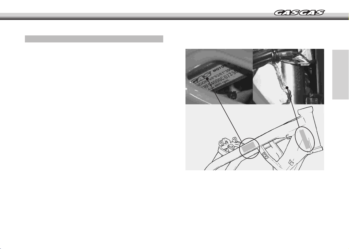
IDENTIFICATION
MOTORCYCLE IDENTIFICATION CODE
The motorcycle identification code is engraved on the steering stem.
AUTHORIZATION PLATE
The motorcycle has its own corresponding authorization plate
including information such as the identification Code. The information
on the authorization plate must correspond to the data in the vehicle
documents.
7
Page 8
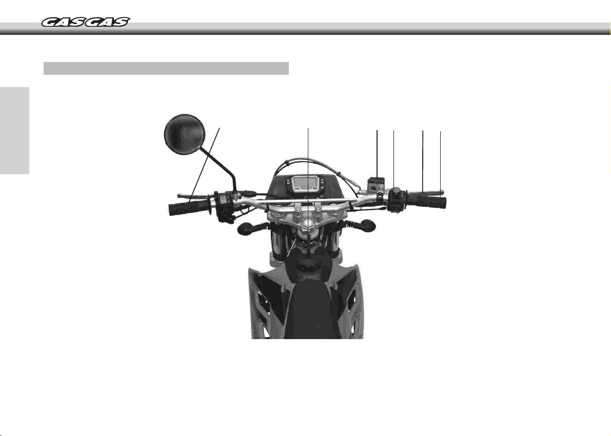
LOCATION OF COMPONENTS – OPERATION
LOCATION OF COMPONENTS
1 2
4
3
6
5
1- Clutch lever
2- Fuel tank cap
3- Front brake fluid tank
4- Engine start button
5- Front brake lever
6- Accelerator control
8
Page 9
1
2
3
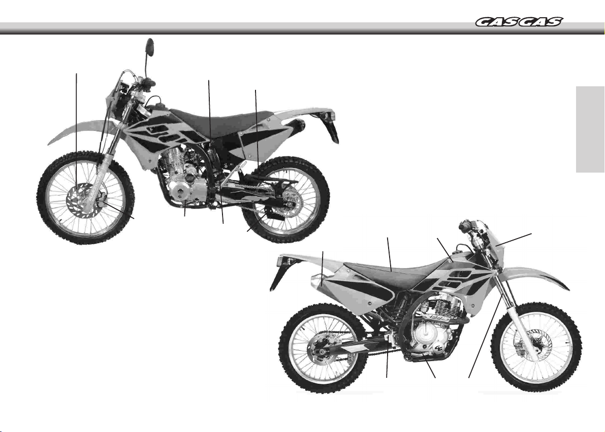
8- Silencer
9- Seat
10- Fuel tank
11- Headlight assembly
12- Front suspension
13- Rear brake pedal
14- Rear brake fluid tank
7
1- Front brake disk
2- Air filter
3- Chain
4- Chain guide
5- Rear shock absorber
6- Gear shift pedal
7- Front brake callipers
6
5
4
8
9
14
LOCATION OF COMPONENTS – OPERATION
10
13
12
11
9
Page 10
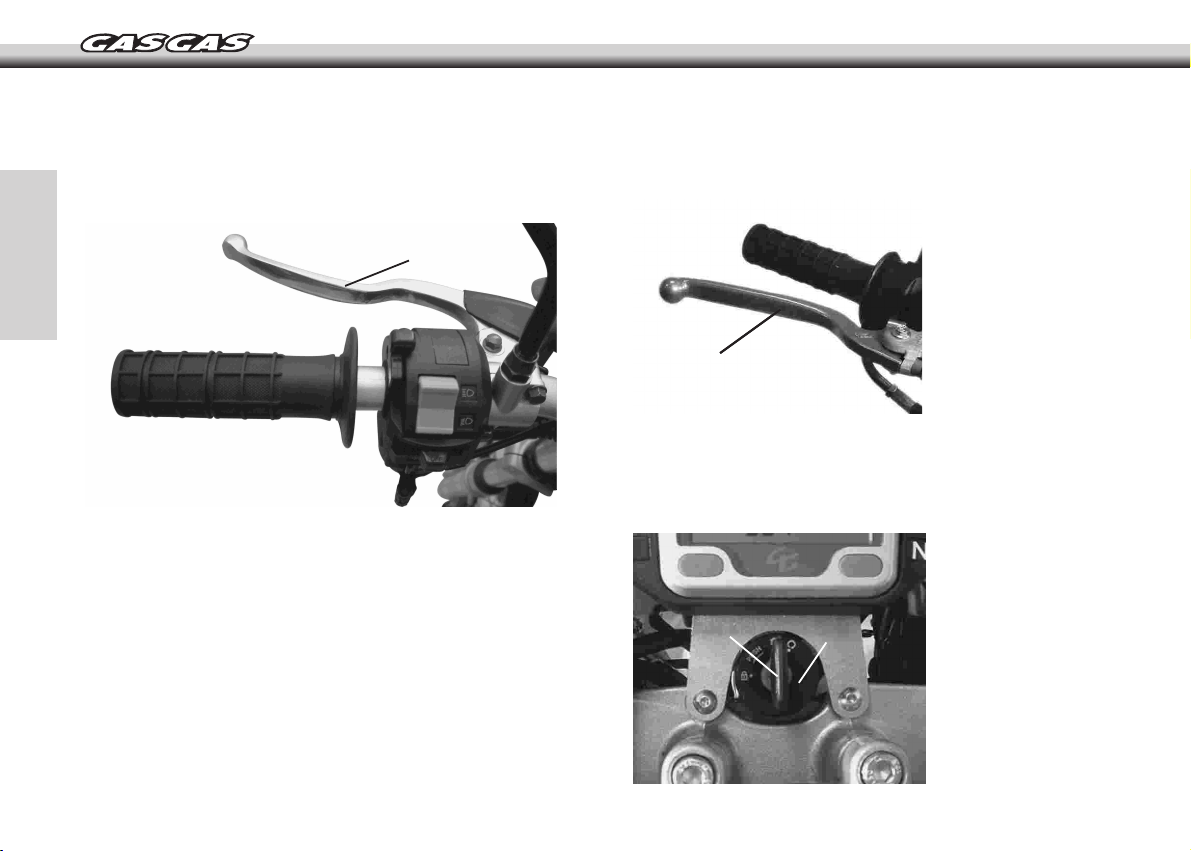
CLUTCH
FRONT BRAKES
The clutch lever A is located on the left hand side of the handlebars.
To adjust the cable, see the section "maintenance instructions".
A
The front brake lever A is located on the right hand side of the
handlebars.
A
IGNITION KEY AND STEERING LOCK
The ignition key A comes with the motorcycle and is inserted into
the lock cylinder B located at the front of the handle bars.
A
B
LOCATION OF COMPONENTS – OPERATION
10
Page 11
In the position everything is off and neither the lights or the horn
will function. The battery is not used. In this position the hazard lights
will not work either.
In the position the ignition is turned on, the engine may be started
and both the lights and the horn may be used.
The battery is used. In this position the hazard lights will operate.
Note
The motorcycle is fitted with a safety device allowing the engine
to be started while the gear is engaged. See the section "Starting
the engine".
The ignition key also operates the steering lock.
To activate the lock, insert the ignition key then:
- rotate the handlebars all the way to the left.
- from the position rotate the key to the left while pressing down
to the position.
- remove the key; the steering is now locked.
LOCATION OF COMPONENTS – OPERATION
11
Page 12
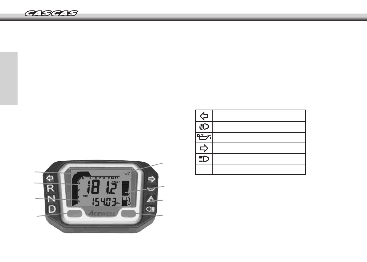
MULTI FUNCTION INSTRUMENT PANEL
AND INDICATOR LIGHTS
The multifunction apparatus, which is waterproof, has 4-8 LED
indicators on both sides of a central indicator screen
This central indicator screen, made of liquid crystal and with
illumination, gives information about the rpm, speed, journey,
kilometres travelled, time, average speed, maximum speed, length
of time with motor running and total time. The data relative to the
distance travelled and total time of use is stored in the memory,
even when the apparatus is switched off. When the multifunction
apparatus is not activated, it displays a clock.
The wheel circumference value is adaptable, as is the measuring
system (metric or imperial).
The number and distribution of the LED indicators, and the amount
of information on screen may vary according to model.
Panel description
1. RESET button
2. 2nd row of indicators
3. 1st row of indicators
4. Tachometer with bar graph
5. Tachometer scale
6. Fuel indicator bars (optional)
7. LED indicator symbols
8. MODE button
Description of symbols
Left indicator / Green
Dipped headlights / Green
Motor oil / Red
Panel
4
3
2
1
LOCATION OF COMPONENTS – OPERATION
12
Right indicator / Green
Full headlights / Blue
5
Neutral / Green (Optional)
N
6
7
8
Page 13
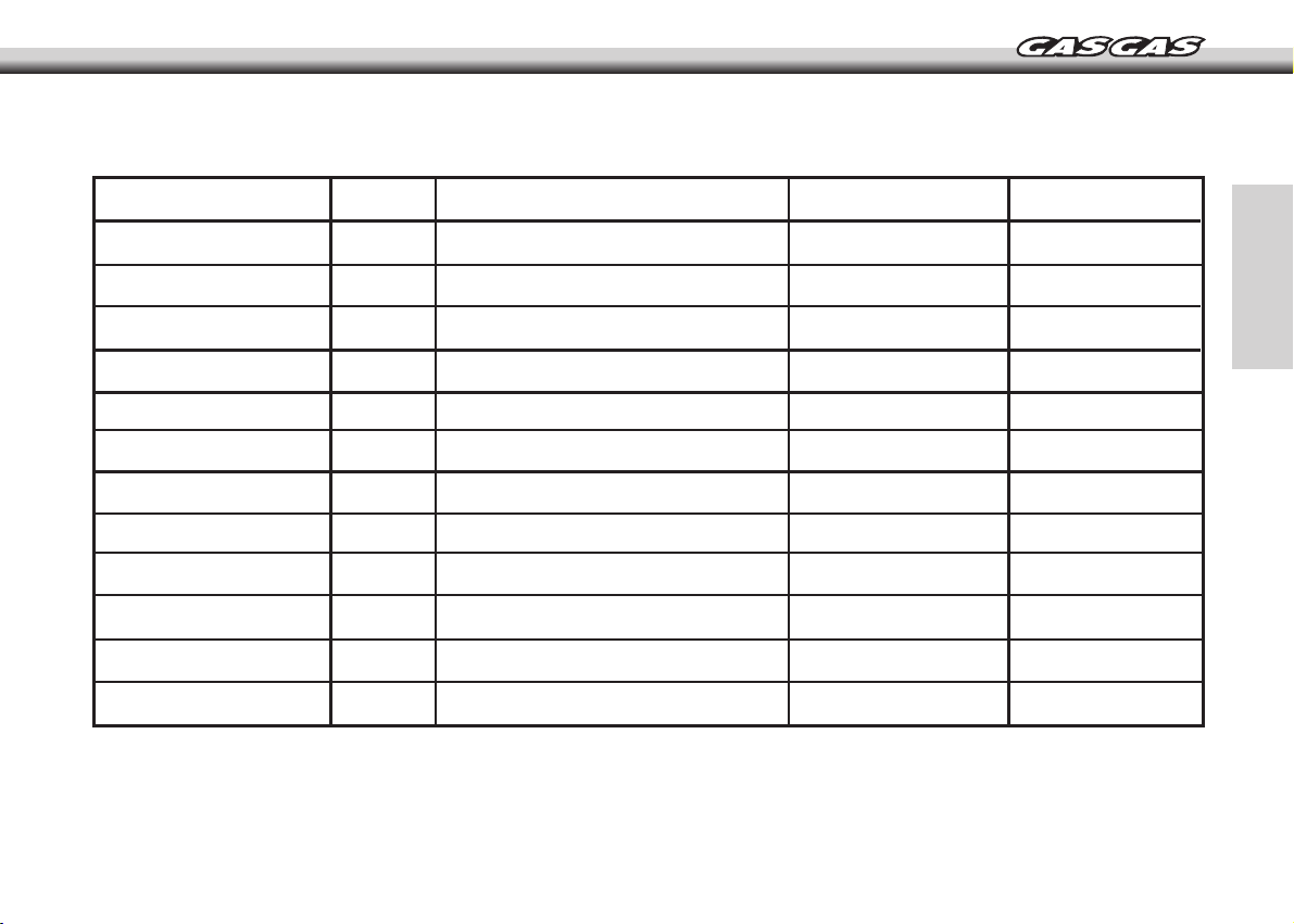
Technical characteristics
FUNCTIONS Symbol TECHNICAL CHARACTERISTICS INCREMENTS PRECISION
Bar tachometer 500 - 11,000 rpm 500 rpm
Digital Tachometer RPM 100 - 19,900 rpm 100 rpm
Gear change indicator RPM 100 - 19,900 rpm 100 rpm
Maximum tachometer value 100 - 19,900 rpm 100 rpm
Speedometer 2.3 - 300 kmph (187.5 mph) 0.1 kmph o mph
Maximum speed gauge MAX 2.3 - 300 kmph (187.5 mph) 0.1 kmph o mph
Average speed gauge AVG 2.3 - 300 kmph (187.5 mph) 0.1 kmph o mph
Trip counter 1 and 2 TRIP 1&2 0 - 999.9 km o 0 - 624.9 miles 0.01 km o miles
Mileometer ODO 0 - 999,999 km o 0 - 624,999 miles 0.1 km o millas
± 1% o ± 0,1
km/h / m/h
± 1% o ± 0,1
km/h / m/h
± 1% o ± 0,1
km/h / m/h
± 0.1 %
± 0.1%
Operation time RT 0:00'00" - 99:59' 59" 1 second
Total time TT 0:00' - 9999:59' 1 minute
Clock 0:00'00" - 23:59' 59" 1 second/1 minute
Initial voltage: 12v CC.
Speed sensor: Non-contact magnetic sensor.
Tachometer input: CDI (capacitor discharge ignition) or ignition coil signal.
Wheel circumference adjustment: 1 mm - 3.999 mm (1 mm increments).
Working temperature: -10 ºC - + 80 ºC (engine casing interior).
Fuel sensor resistance: 100 (only in models with fuel level indicator).
LOCATION OF COMPONENTS – OPERATION
± 50 PPM
± 50 PPM
± 50 PPM
13
Page 14
Functions
RPM: Bar
Tachometer with bar graph. The bar graph of the tachometer displays
up to 11,000 rpm.
RPM: Digital Tachometer
The rpm is shown in the second row. The digital tachometer displays
up to 19,900 rpm The tachometer signal can be read from the CDI
(Capacitor Discharge Ignition) or the ignition coil.
TRIP: Journey counter
This appears in the second line of the screen. The TRIP function
contains the vehicle's accumulated mileage since the last RESET
operation.
ODO: Mileometer
It shows the total mileage accumulated by the vehicle. The data is
stored in the memory, even when the device is not running.
Gear change indicator according to rpm
This function permits setting an indicator for changing gear at a
specific rpm level The tachometer bar flashes when the rpm reaches
the specific level and stops flashing when the gear is changed.
MAX RPM: Maximum tachometer value
It appears in the 2nd row. It shows the highest level reached by the
tachometer since the last resetting of the data.
SPD: Speedometer
The speedometer information appears in the first line of the screen
It shows up to 300 km/h or 187.5 mph.
MAX: Maximum speed gauge
The MAX value appears in the 1st line. It shows the highest speed
reached since the last resetting of the data.
AVG: Average driving speed
The AVG value appears in the 1st line. It calculates the average
speed since the last RESET operation.
LOCATION OF COMPONENTS – OPERATION
14
RT: Time of use controller
It calculates the total time in use since the last RESET operation. It
starts counting from the moment that movement begins.
TT: Total time of use controller
It calculates the vehicle's total time in use. It starts counting from the
moment that movement begins. The data is stored in the memory,
even when the device is not running.
12/24 hour clock
It shows the time in either 12 or 24 hour formats.
Fuel level indicator (only vehicles with this function)
It has 7 bars showing the amount of fuel remaining in the fuel tank.
The last bar flashes to indicate that the fuel level is too low.
Page 15
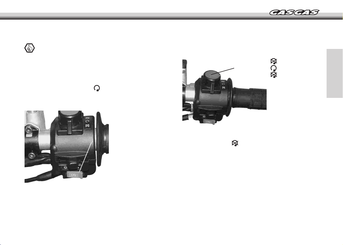
ELECTRIC START BUTTON
Note
The motorcycle is fitted with a safety device allowing the engine
to be started while the gear is engaged. See the section "Starting
the engine".
The electric starter button A is located on the right-hand side of the
handlebars and only operates if:
- the ignition key is in the position .
- if the clutch is pressed in or the gear change pedal is in neutral.
ENGINE STOP BUTTON
The switch A is located on the right-hand side of the handlebar and
has three positions:
- Engine off
A
- Engine running
- Engine off
A
To stop the engine, moved the switch A 21 of the two positions
indicated by the symbol .
LOCATION OF COMPONENTS – OPERATION
15
Page 16

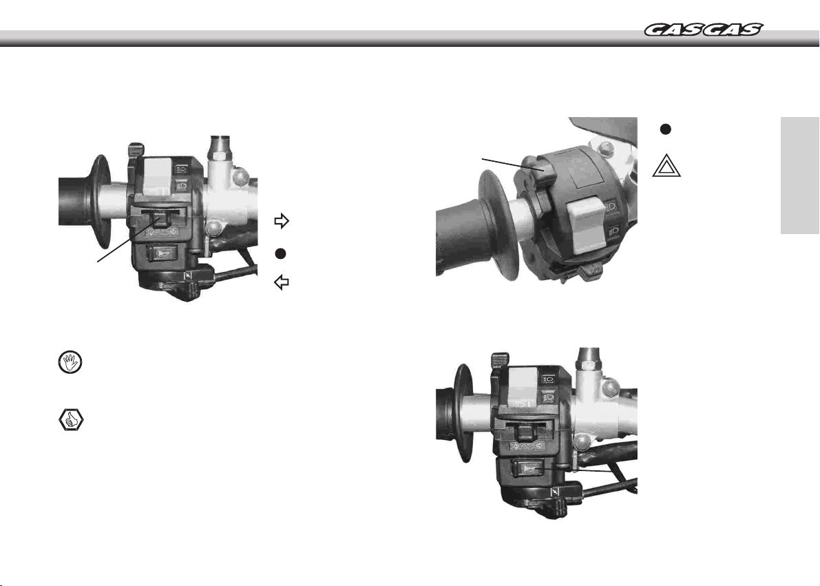
LIGHTS AND INDICATORS
Note
With the ignition in position it is not possible to activate the
lights or the horn. In this position the hazard lights will not work
either.
Lights
A
B
The switch A is located on the right-hand side of the handlebar and
has three positions:
- Off
- Side lights
- Low beam / high beam
To switch from low beam to high beam operate the switch B located
on the left hand side of the handlebars.
- Low beam
- High beam
Light burst
To operate the light burst, press the switch B to the position
.
Note
The switch A does not need to be activated to use the light
burst. However the ignition key must be in the position .
LOCATION OF COMPONENTS – OPERATION
16
Page 17
Turn indicators
The switch A is located on the left-hand side of the handlebar and
has three positions:
Right hand side
indicator
Indicator
A
Hazard lights
WARNING
Regarding the use of these lights, follow the legal requirements
of each country.
Note
The hazard lights only operate when the ignition is turned on.
off
Left hand side
indicator
The switch A is located on the left-hand side of the handlebar and
has two positions:
Hazard
lights off
A
Hazard
lights on
HORN
The button A, located on the left hand side of the handlebars,
operates the horn.
A
LOCATION OF COMPONENTS – OPERATION
17
Page 18
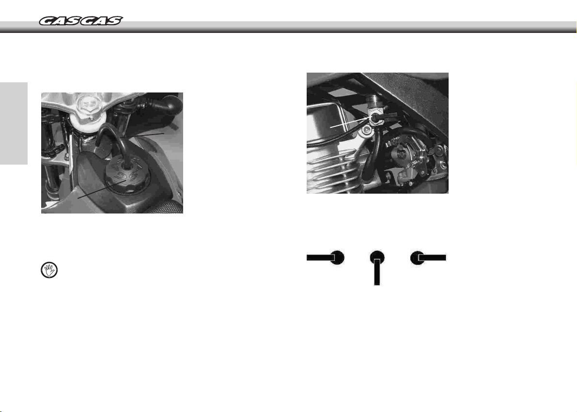
FUEL TANK
The fuel tank holds 7.4 l.
FUEL CUTOFF
B
A
The tank has a rapid access cap A and a tube for ventilation B to
clear and vapours that may form.
- Turn the cap to the left to open.
WARNING
Regularly check the cap seal and vent hose to ensure they are
leak proof. Risk of spillage!
LOCATION OF COMPONENTS – OPERATION
18
A
This has three positions:
The diagrams below show the position of the fuel tap (A) for each
case.
1 2 3
RECOMMENDED FUEL
Use lead-free petrol with an octane rating of 95 or higher.
1- Reserve
2- Open
3- Closed
Page 19

WARNING
If knocking occurs, try a different brand of petrol or higher
octane grade.
DANGER
Always stop the engine and do not smoke. Gasoline is extremely
flammable and can be explosive under certain conditions. Make
sure the area is well ventilated and free from any source of
flame or sparks; this includes any appliance with a pilot light.
THROTTLE CONTROL
A
GEARBOX
The motorcycle has 5 gears. It is a sequential gearbox, which
means that in order to reach third gear from first gear, second
gear must first be engaged, that is, the gears go up or down
gear by gear.
To engage the first gear from neutral, press on the clutch,
press the gearshift pedal all the way down then release the
clutch slowly.
Neutral is located between first gear and second gear.
2, 3, 4, 5
N
1
Moving the control A to the left will close the throttle and restrict
the flow of air in the carburettor jet. While the control A remains in
this position, the air/fuel mixture is enriched and this will facilitate
cold starting. See also "Starting a cold engine".
WARNING
To ensure correct gear engagement, operate the gearshift pedal
firmly so that the transition is complete.
Incomplete or erratic insertion of gears could cause damage to
the transmission system. Accident risk!
LOCATION OF COMPONENTS – OPERATION
19
Page 20

BRAKE PEDAL
WARNING
Do not start the engine or ride the motorcycle when the stand
is down.
B
A
The rear brake pedal is located in front of the right hand side footrest
and may be adjusted to the position of the driver.
SEE MAINTENANCE INSTRUCTIONS.
STAND
DANGER
Danger, risk of physical injury! Use the stand with care.
The uncontrolled return of the stand to its rest position could
cause injury to the user or to others
LOCATION OF COMPONENTS – OPERATION
20
A - Rear brake pedal
A
- Push the stand A downwards to the ground by foot until it supports
the weight of the motorcycle.
Ensure that the surface on which the stand rests is sufficiently hard
so that the motorcycle remains in a stable position.
- To take up the stand, remove the weight of the motorcycle by
inclining it - the spring B will return the stand to its resting position.
Page 21

DRIVING INSTRUCTIONS
STARTING THE ENGINE
DANGER
Do not start or leave the engine idling in closed spaces.
Exhaust fumes are highly toxic and may result in loss of
consciousness or even death. When the engine is running,
ensure that there is always adequate ventilation.
Note
The motorcycle is fitted with a safety device allowing the engine
to be started while the gear is engaged.
To start the motorcycle, proceed as follows.
- Open the fuel tap.
- Put the gearbox into neutral or even hold in the clutch lever during
the starting operation.
- Rotate the ignition key A clockwise to the position , the electric
circuits are activated and the motorcycle may start.
- Without using the throttle, press the electric start button B.
A
WARNING
When the key remains in the engine start position: If the
engine is not started then a loss of battery electrical potential
may occur.
STARTING A COLD ENGINE
WARNING
Do not fully load the motorcycle while the engine is cold.
Allow the engine to run at idle speed or drive slowly until the
engine reaches normal operation speed.
B
21
Page 22

A
After some seconds, and depending on the outside temperature, the
engine will reach a higher and more stable speed. This means that
it has reached normal operation temperature. At this moment remove
the choke by turning the control A to the right hand side.
WHAT TO DO WHEN THE ENGINE IS FLOODED
Note
If the engine will not start, remove the spark plug and dry it.
See "Removing the spark plug".
- Once the engine is running, open the fuel tap.
Stopping the engine
- Brake the motorcycle and put the gearshift pedal in neutral.
- Completely close the accelerator pedal and use the engine stop
button.
- Rotate the ignition key anticlockwise to the position .
- Close the fuel tap.
STOPPING THE MOTORCYCLE
DANGER
When driving in wet conditions or after washing the motorcycle,
the brakes may be wet. If so, then the braking capacity is reduced
until the braking elements are dry. Drive carefully and lightly apply
both brakes in order to dry them.
- Close the fuel tap.
- Following the instructions described in STARTING THE ENGINE,
operate the starter button with the throttle completely open (full
throttle) and the choke control all the way to the right; release the
throttle control as soon as the engine starts.
DRIVING INSTRUCTIONS
22
WARNING
If the ground is slippery or loose then give preference to the
rear brake.
Depending on circumstances and ground surface, it may be
better to use the front or rear brakes independently.
Gear down gradually using the engine braking capacity.
Page 23

For maximum deceleration, close the throttle A and apply both front
and rear brakes.
A
RUNNING IN PERIOD
WARNING
Brutal acceleration during the run in period may cause engine
damage.
All of the moving parts in the engine have been made to a high level
of precision in order to obtain a quality contact surface and correct
positioning.
However, correct engine care during the first hours of use is vital for
obtaining the best from your motorcycle.
Therefore, we recommend:
- Start the engine and let it run at idle until the engine is thoroughly
warmed up.
- Stop the engine and wait for it to completely cool.
- Start the engine once again. For the first hour of use or for the first
100 Km, use the engine at a moderate speed.
- Never run the engine at maximum rpm.
- Vary the engine speed consistently using the throttle control.
Note
The spark plug may be soiled if the engine is used at a low
speed during the running in period. If this occurs then replace
the standard spark plug by a higher temperature spark plug for
the running in period only. See the section regarding extraction
of the spark plug.
Following the run-in period, fit a new standard spark plug.
DRIVING INSTRUCTIONS
23
Page 24

MAINTENANCE INSTRUCTIONS
MAINTENANCE CHART
Article Period Period Period
First 5 hours every 30 hours every 60 hours
Air filter Inspect the following every time that the motorcycle has been used or when necessary
*Bolts on the silencer and the connections
for the silencer T T T
*Valve tolerances I - I
Spark plug - I R
Fuel lines I I I
*Change every 4 years
Engine oil R R R
Oil strainer C - C
Clutch I I I
Chain Clean, lubricate and inspect each time the motorcycle has run
*Brakes I I I
Brake lines I I I
*Revise every 4 years
Brake fluid I I I
*Change every 2 years
Tyres
*Steering assembly I - I
*Front forks I - I
*Rear suspension I - I
*Chassis bolts and nuts T T T
Note: I = Inspect and clean, adjust, replace or lubricate if necessary; R= Replace; T= Tighten; C= Clean
Inspect tyres for damage and check the tyre pressure every time the motorcycle has run
24
Page 25

CLUTCH
Correct clutch cam play is 2-3 mm.
Adjusting
Correct clutch lever play is 2-3 mm.
WARNING
Lower play than that indicated will reduce the clutch effectiveness
and the clutch useful life.
To adjust the clutch lever play, proceed as follows:
- Remove the cap A.
- Loosen the lock nut C.
- Rotate the adjustment B in one direction to achieve the indicated
play.
- Tighten the lock nut C to lock the adjustment B in position.
- Fit the protection cap.
C
B
A
A- Protection cap
B- Adjustment
D
Note
If the clutch lever adjustment is at its limit, play must be adjusted
by using the clutch cam.
C- Lock nut
D- Clutch lever
WARNING
Lower play than that indicated will reduce the clutch effectiveness
and the clutch useful life.
To adjust the clutch cam play, proceed as follows:
- Loosen the adjustment nuts B and rotate in one direction until the
correct play is achieved.
- Tighten the adjustment nuts B to lock the adjustment in position.
A
A- Cam
B- Adjustment nuts
B
MAINTENANCE INSTRUCTIONS
25
Page 26

BRAKES
Brake disc wear is automatically compensated mechanically and
has no effect on the front brake lever or on the rear brake pedal.
The only adjustments that need to be made are: Position and play
both on the front brake lever and the rear brake pedal.
If the front brake has a spongy feeling then it is possible that
there is air in the hydraulic circuit. We recommend that you visit
a GAS GAS workshop immediately.
- Ensure that front brake lever adjustment is correctly suited to
your hand.
Position and play of the front brake lever
- Adjust the position of the front brake lever according to the size of
your hand. Note that the front brake lever should have a play of at
least 3 mm when in rest position. Adjust the position and play of
the brake lever using the bolt A.
A
A - Adjustment bolt
DANGER
Never reduce the play of the front brake lever to less than
3 mm. If the play is reduced then the brake cylinder acts on the
front brake pads which then remain in permanent contact with
the brake disc; this could result in brake failure due to
overheating.
MAINTENANCE INSTRUCTIONS
26
Position and play of the rear brake pedal
The rear brake pedal should have a play of between 1 to 3 mm when
in rest position.
- Loosen the bolt A and adjust the play using the pin B.
- Tighten the nut A once again.
C
A - Nut
B
A
- Ensure that the rear brake pedal adjustment is correct; if necessary
repeat the adjustment until it is correct.
- Ensure that the pedal operates correctly and that it does not rub
on any element of the motorcycle.
B - Pin
C - Play
Page 27

DANGER
Never reduce the play of the rear brake pedal to less than 10
mm. If the play is reduced then the brake cylinder acts on the
rear brake pads, which then remain in permanent contact with
the brake disc; this could result in brake failure due to
overheating.
If the rear brake has a spongy feeling then it is possible that
there is air in the hydraulic circuit. We recommend that you visit
a GAS GAS workshop immediately.
BRAKE FLUID
- Check the condition of the brake fluid using the level inspection
windows on both the front brake tank A and rear brake tank B. If the
brake fluid is dark or appears dirty then go immediately to an approved
GAS GAS workshop to replace the fluid.
A B
WARNING
Brake fluid absorbs ambient humidity and degrades with time.
So that the brake fluid retains its specifications, use only fluid
from sealed containers and respect the replacement periods as
shown in the MAINTENANCE CHART.
Brake fluid is corrosive to paintwork. Avoid contact between
the fluid and paintwork.
- Only use fluid in accordance with DOT 3 or DOT 4.
MAINTENANCE INSTRUCTIONS
27
Page 28

Brake fluid level inspection
- Check the brake fluid level using the inspection windows on both
the front A and rear B brake tanks. The level should at least reach
halfway up the inspection window.
If brake fluid is required:
- Ensure that brake fluid is not leaking from: front and rear brake
cylinder seals, hoses and joints. If there is any leak, visit a GAS
GAS workshop immediately.
- Add brake fluid, complying to the DOT 3 or DOT 4 standards, to
the corresponding brake fluid tank in order to re-establish the correct
level.
Checking brake pad wear
- Check the thickness of both the front and rear brake pads.
- Minimum brake pad thickness A: 1 mm
- If any brake pad is less than 1mm thick then replace the complete
set.
1 mm
HANDLEBARS
Adjustment
In order to better suit the driver size and preferences, the handlebar
position may be adjusted forwards or backwards.
Loosen the handlebar A clamp bolts B then place the handlebars
in the required position.
B
A
Tighten the bolts to 25 Nm, firstly the forward bolts then the rear
bolts. If the handlebars are correctly installed, there will be a minimal
gap at the front and rear of the clamp after tightening A.
A
MAINTENANCE INSTRUCTIONS
28
Page 29

STEERING
Steering - adjustment
DANGER
Handlebars with excessive play or an incorrect adjustment are
extremely dangerous for driving.
Steering - verification
The steering should always be kept adjusted so that the handlebar
will turn freely but without excessive play
To check the steering adjustment, proceed as follows:
- lift the motorcycle off the ground using a support under the chassis
so that both wheels are suspended.
- move the steering gently from side to side.
If the steering continues to turn when released then this means that
the some play has resulted from use.
Make a final test:
- with the motorcycle firmly attached to the supports and with the
wheels suspended, stand in front of the motorcycle; pull and push
the handlebars forward and back.
- Stabilise the motorcycle using a solid support under the chasis.
- Keep the front wheel off the ground.
- Remove the handlebar by loosening the handlebar clamp bolts A.
WARNING
Always work with the handlebars in such a way that cables and
hydraulic lines are not damaged.
-Loosen the steering stem bolt B.
-Loosen the steering stem bolt C.
A
B
C
If the steering shaft moves
then the steering must be
adjusted.
MAINTENANCE INSTRUCTIONS
29
Page 30

E
D
- Loosen the bolts D on both sides then remove the upper suspension
plate E.
- Rotate the steering adjustment nut using the special spanner in
order to obtain the appropriate adjustment.
- Fit the upper suspension plate E.
- Fit the washers, tighten the steering shaft bolt C, the steering shaft
nut B and the bolts D to the correct torques below:
Steering nut: 44 Nm (4.5 Kgm)
Suspension plate bolts: 22 Nm (2.25 Kgm)
- Check the steering once more and adjust again if necessary.
- Refit all removed parts.
ENGINE OIL
The oil must comply with the SAE 10W-50 standard, classification
API SF or SG.
Note
If you are using the motorcycle in climates with extreme
temperatures then choose the most suitable engine oil using
the attached table as a guide.
20W-50
ENGINE OIL
ºC -30 -20 -10 0 10 20 30
TEMP.
ºF -22 -4 -14 32 50 68 86
15W-40 15W-50
10W-40 10W-50
10W-30
Oil level
Note
- To keep your engine in perfect working order, regularly check
the oil level and change the oil.
- The engine oil increases in volume when it is hot. Check and
adjust the level when the oil is cold.
- Initially replace the oil after 5 hours of operation and then
every 60 hours. See the maintenance table.
Changing the oil
DANGER
- The engine oil and the exhaust manifold can be very hot and
cause burns. Wait until the oil and the exhaust manifold are cool.
- Exhaust fumes are highly toxic and may result in loss of
consciousness or even death. When the engine is running, ensure
that there is always adequate ventilation.
MAINTENANCE INSTRUCTIONS
30
Page 31

WARNING
- Avoid all contact with the engine oil; this is a health risk and
may cause irritations.
- Keep new or used oil away from the reach of children and
animals.
- Wash yourself with neutral soap if oil comes in contact with
your skin.
- Used oil should be kept in an appropriate recipient for
subsequent recycling according to current legislation.
B
Note
- Change the oil when the engine is warm; this will facilitate the
drainage of the oil from the drain in the lower part of the engine.
- Always use genuine GAS GAS parts.
To change the oil, take the following steps:
- Ensure that the motorcycle is on a suitable, solid, horizontal surface,
for example a stand.
- Place an adequately sized container underneath the engine.
- Remove the bolt from the drain A.
A
C
- Remove the oil level rod B.
- Allow the used oil to completely drain out.
- Replace the seal washer and replace the drain bolt A.
- Add oil in small quantities (for example 150 ml) and check the oil
level using the oil level rod as usual (clean before checking).
Note
The engine has a visor on the right hand side cover – on the
clutch side, close to the brake pedal – this can be used to check
the approximate oil level.
- The oil level should never exceed the upper mark indicated by the
grooved zone C on the oil level rod.
- Start the engine and keep it running for several minutes to ensure
that oil is not leaking from the drain plug.
- Stop the engine.
- Ensure that the oil level is correct and if necessary add more oil.
MAINTENANCE INSTRUCTIONS
31
Page 32

Cleaning the strainer
Note
- The engine oil circuit, has a strainer to filter out particles that
may contaminate the oil.
- The oil strainer should be cleaned as indicated in the
Maintenance table.
WARNING
Used oil should be kept in an appropriate recipient for subsequent
recycling according to current legislation.
- Empty the engine oil as indicated in the section Changing the
engine oil.
- Remove the plug A located on the left hand side of the engine.
A
- Remove the spring B and the oil strainer C.
- Clean the strainer using petrol and dry using compressed air in
order to remove the remains of petrol.
B
C
B- oil strainer
C- spring
- Fit the strainer, the spring and the cap.
- Refill the oil and ensure that there are no leaks as indicated in the
section regarding oil changes.
CARBURETTOR
Adjusting the throttle control cable
The throttle control should have a play of 2-3 mm.
If the play is not as indicated then proceed as follows:
A
C
A - Throttle control
B
B - Lock nut
C - Adjustment
MAINTENANCE INSTRUCTIONS
32
Page 33

- Check that the throttle grip turns smoothly.
- Loosen the lock nut B.
- Rotate the adjustment bolt C until the indicated play is reached.
- Tighten the locknut B.
Adjusting idle speed
DANGER
The exhaust gasses are highly toxic. The idle adjustment
operation must be carried out in open spaces or in suitably
ventilated premises.
The carburettor has an idle adjustment screw A, which acts on the
fuel opening cylinder in the carburettor.
The bolt B adjusts the supply of air-fuel for the deceleration system.
A
B
To set the engine speed to a minimum or slow the engine down then
take the following steps:
- Use the motorcycle until the normal operation temperature is
reached.
- Stop the engine and secure the motorcycle (for example on a
support stand).
- Start the engine.
- Rotate the bolt A until the engine runs continuously.
Note
- Rotating the screw A clockwise will increase the engine speed.
- Rotating the screw A anticlockwise will decrease the engine
speed.
- Rotate the bolt B until the engine reaches the highest speed.
Note
- Tightening the screw B will restrict the flow of air-fuel mixture
- Loosening the screw B will open the flow of air-fuel mixture
- Tighten the screw B about 1/4 of a turn.
Rotate the bolt A until the engine reaches the required idle speed.
MAINTENANCE INSTRUCTIONS
33
Page 34

SPARK PLUG
Note
- The spark plug should be regularly checked, according to the
"Maintenance table" or if the engine has a problem. See the
section "Trouble shooting".
- Note that if the engine performance falls then this could be
due to the spark plug.
Standard spark plug TORCH D8RTC
Electrode spacing 0.7 to 0.8 mm (0.028 – 0.031 in)
WARNING
Incorrect installation of the spark plug or the choice of an
incorrect temperature grade may cause serious damage to the
engine. This damage is not covered by the guarantee.
Always use spark plugs recommended by GAS GAS. Consult
the dealers or a qualified mechanic to know which spark plug
is best for your bike.
Spark plug - removing
To remove the spark plug, take the following steps:
- Remove the cap A from the spark plug.
- Remove the spark plug B from its allotment using the special spark
plug wrench.
Note
Check the colour and the appearance of deposits on the spark
plug. These deposits indicate if the standard spark plug is the
most suitable for your motorcycle or if it should be replaced by
another of a different temperature grade.
A
B
- If there is soot on the spark plug then clean using a metal brush.
- Check and, if necessary, adjust the electrode spacing to between
0.7 - 0.8 mm (0.028 - 0.031 in).
WARNING
If the spark plug electrodes are oxidised, damaged or the
insulation is broken then replace the plug.
MAINTENANCE INSTRUCTIONS
34
Page 35

- Fit the spark plug and tighten to the specified torque of 11 Nm (1.0
kgm). See also the "Tightening torques table".
- Refit the hood for the spark plug.
Note
To ensure correct operation of the spark plug, keep the protection
hood clean and dry.
AIR FILTER
A clean air filter will provide good engine performance and prolong
its useful life.
An obstructed air filter restricts the air intake of the engine, increasing
the petrol consumption and reducing the engine power as well as
causing the destruction of the spark plug.
WARNING
If dirt enters the engine then this will lead to excessive wear
and engine damage. Inspect the air filter regularly as indicated
in the Maintenance table.
Air Filter - Cleaning
DANGER
When cleaning the air filter, ensure the area is well ventilated
and free from any source of flame or sparks; this includes any
appliance with a pilot light.
Do not use petrol to clean the filter as this could result in an
explosion.
To remove the air filter, proceed as follows:
-Remove the cover A by rotating the clip B.
B
A
-Remove the retention rod C.
- Remove the filter element assembly
- Stuff a clean, lint-free towel into the intake manifold so no dirt is
allowed to enter.
- Clean inside the filter housing using a damp cloth.
MAINTENANCE INSTRUCTIONS
35
Page 36

- Remove the cage B from the air filter A.
- Clean the filter in a bath of filter cleaning liquid using a gentle brush.
- Check the filter for damage such as rupture, scratching, hardening,
or shrinkage. If it is damaged then replace it, otherwise dirt will
enter the carburettor.
- Grease all of the connections and bolts of the air filter and inlets.
- Re-install the air filter in the motorcycle and make sure it is correctly
secured.
WHEELS
Tyre pressure
Tyre pressure affects traction, handling, and tyre life.
- Adjust the tyre pressure to suit ground conditions and rider
preference, but do not deviate excessively from the recommended
pressure.
- Squeeze it and dry it with a clean cloth. Do not twist the filter or
expose it to pressurized air otherwise it will be damaged.
MAINTENANCE INSTRUCTIONS
36
Note
Tyre pressure should be tested when the tyre is cold before
driving.
Page 37

Ground conditions
SECONDARY TRANSMISSION CHAIN
- Wet, sandy, muddy and slippery ground: reduce tyre pressure.
- Hard ground, stony ground: increase tyre pressure.
Adjusting the wheel spokes
DANGER
The wheel spokes must be evenly tightened.
One or more loose or incorrectly tightened wheel spokes may
put the rim off-centre and put extra tension on the remaining
spokes which may in turn rupture. Accident risk!
Centring the rim
Note
If the rim is bent or crooked then it must be replaced.
In case of small deformations of the rim, go to an approved GAS
GAS workshop or specialist workshop.
DANGER
A chain in bad condition, inadequately maintained or incorrectly
adjusted may jump or rupture leading to a loss of control of the
motorcycle.
Note
The chain should be regularly examined, according to the
maintenance table or when the motorcycle is used in adverse
conditions, for example in mud, rain or humid conditions.
Chain slack - Checking
Note
Under muddy or humid conditions, the chain will be under more
tension. Eliminate mud from the chain before checking the play.
The distance between the chain B and the chain pad A should be
about 30 a 50 mm.
A- Wheel spoke
adjustment tool
MAINTENANCE INSTRUCTIONS
37
Page 38

- To check this, rotate the rear wheel until the chain becomes more
tense.
- Lift the chain B by hand in the area of the pad A and measure the
distance between the pad surface and the lower part of the chain
links.
- If the indicated specification is not reached then adjust the chain
as described below.
Note
When checking the chain tension, rotate the rear wheel to check
for damaged links and lost connections as well as worn or
damaged teeth on the drive pinion and sprocket.
Chain slack - Adjusting
Note
The operation is described from the swinging arm side.
- Loosen the axle nut C.
- Loosen the lock nuts B.
- Rotate the chain adjustment bolt A to reach the measurement
indicated in the section "Chain slack - Checking".
WARNING
The operations described should be repeated on the opposite
side given that the rear wheel must be aligned with the front
wheel. To align both wheels, use the string method and adjust,
if necessary, the adjustment bolts as described above.
DANGER
An incorrectly aligned wheel will cause abnormal tyre wear and
may be dangerous for driving.
-Tighten the lock nuts.
-Tighten the rear axle nut to 98 Nm.
DANGER
An incorrectly tightened rear axle nut will be extremely dangerous
for driving.
B
C
A
MAINTENANCE INSTRUCTIONS
38
A - Adjustment bolt
B - Lock nut
C - Axle nut
Rear
- Rotate the wheel and measure the position when the chain is most
tense. Re-adjust if necessary.
Chain wear
WARNING
Replace the chain when the length excedes 2% of its original
length*.
Only use original replacement parts.
Page 39

When the chain is replaced, the engine output pinion and the rear
sprocket should also be replaced. If the teeth on these element are
worn then this will lead to a rapid wear of the new chain.
Check the engine output pinion and rear sprocket teeth and replace
them if they are worn.
* the chain must be removed by opening the connection link. The
length is measured from the two ends of the chain.
WARNING
Whenever the chain is removed, ensure that the clip on the chain
connection link is correctly installed with the closed part of the
"U" in the direction of rotation.
A
B
A
Chain guides - Checking
Check the chain guide A as well as the upper and lower parts of the
chain pad B. If there is any serious damage then replace these
elements.
A - Clip
B - Direction of
rotation of the chain
Note
Only use original replacement parts.
BATTERY
Note
This battery is maintenance free and checking the fluid level is
not required. It is advisable to check the charge of the battery
periodically.
Battery - removing
To remove the battery, follow these steps:
MAINTENANCE INSTRUCTIONS
39
Page 40

B
A
C D
E
If the battery voltage is above 12.6 V, the battery can be installed
on the vehicle without having to recharge it.
Constant voltage charge mode
- Constant voltage = 14.4 - 14.7 V
- Initial charge current = 0.1 - 0.5 Cn
- Charge duration = 6 hours minimum / 24 hours maximum.
Constant power charge mode
- Maximum charge current = 0.1 Cn
- Recommended charge time = 5 - 8 hours.
- The product (charge current) x (charge duration) must be within
the range: 0.5 - 0.8 Cn.
- Remove the bolts A and remove the seat B.
- Remove the terminals D carefully so that they do not come into
contact with metal elements.
- Unhook the rubber element E.
- Remove the battery C from its allotment.
DANGER
Hydrogen gas produced by the battery may explode if exposed
to open flame or sparks.
Keep the area ventilated and free from naked flames.
The operating instructions for the battery are as follows:
- Check the battery voltage in open circuit status (disconnected).
- If the battery voltage is below 12.6 V, or if the storage period has
exceeded 6 months, the battery has to be recharged following the
instructions in paragraph 3.
MAINTENANCE INSTRUCTIONS
40
DANGER
Inverting the polarity of the battery terminals may cause battery
charge problems and cause damage to the battery system.
The red terminal is positive ( + ) and the black terminal is
negative ( - ).
WARNING
Not using the standard manner of charging may seriously
shorten the battery life.
Never exceed the standard charge.
Note
In case that a different mode of charging is used to those
established here, never exceed the maximum allowed
currents nor the maximum charge duration of 24 hours.
Page 41

THE EXHAUST SYSTEM
The exhaust and the silencer reduce noise and carry the gasses
away from the driver.
If the exhaust is damaged, rusted, dented or split then change it.
Removing the silencer
- Remove the right hand side number plate carrier by removing the
attachment bolts.
- Remove the silencer B attachment bolts A.
A
A
- Loosen the bolt A on the exhaust pipe clamp.
- Remove the silencer assembly
B
FRONT FORKS
Height adjustment
The flat surface around the front fork bars nut-cap should be flush with
the surface of the upper plate.
MAINTENANCE INSTRUCTIONS
A- Clamp
for exhaust pipe
41
Page 42

REAR SUSPENSION
Checking
The rear suspension is fitted with a hydraulic telescopic shock
absorber fitted to the chassis and to the swinging arm by ball joints.
Maintenance of this system consists only of inspecting the ball joints
and the swinging arm joint on the chassis.
LUBRICATION
Note
- Before lubricating each part, clean off any rusty spots with
rust remover and wipe off any grease, oil, dirt, or grime.
- Lubricate the points shown here, with either motor oil or regular
grease, periodically or whenever the vehicle is wet, and
especially after using a high-pressure spray washer.
General lubrication
Lubricate the points indicated with an arrow
- Clutch lever.
- Front brake lever.
- Rear brake pedal.
MAINTENANCE INSTRUCTIONS
42
Note
In order to lubricate the control cables (for example the throttle
control) several lubricants in aerosols are available on the market.
Ask for information from your approved GAS GAS workshop.
Page 43

Lubricating the secondary transmission chain
Lubricate the chain according to the intervals indicated in the
maintenance charge or whenever the motorcycle is used in adverse
conditions such as mud or rain.
Note
Several chain lubricants in aerosols are available on the
market.
- Lubricate both sides of the chain links with chain lubricant. Dry the
excess lubricant.
TIGHTENING NUTS AND BOLTS
Every day before using the bike, rapidly ensure that all bolts and
nuts are tightened. Also make certain that all of the other fastenings
are in place and in good condition.
MAINTENANCE INSTRUCTIONS
43
Page 44

3
2
1
4
6
5
1
16
17
18
20
19
21
22
15
14
11
10
7
9
8
12
13
23
24
25
1- Front and rear wheels
2- Front forks
3- Handle bars
4- Upper plate nut
5- Air filter housing bolts
6- Seat bracket bolts
7- Spokes
8- Front axle bolt
MAINTENANCE INSTRUCTIONS
44
9- Brake hose bolt
10- Bolts and nuts of the
engine brackets.
11- Shift pedal bolts
12- Subframe support bolt
13- Chain guide bolts
14- Chain adjustment nut
15- Drive sprocket bolts
16- Silencer bracket bolts
17- Sub chassis bolts
18- Shock absorber bolts
(rear)
19- Exhaust clamp bolt
20- Upper plate bolts
(suspension)
21- Brake lever bolt
22- Handlebar bolts
23- Rear axle nut
24- Rear brake pedal bolt
25- Swinging arm nut
Page 45

TIGHTENING TORQUE TABLE
PART NUMBER Nm Kgm
E
N
G
I
N
E
C
H
A
S
S
I
S
Tighten all of the bolts and nuts using the correct spanners. If not correctly tightened then motorcycle damage or even an accident could occur.
Engine drain plug 20 2.0
Shift pedal bolt 10 1.0
Spark plug 11 1.0
Calliper mounting bolts 25 2.5
Disc plate mounting screws 10 1.1
Engine mounting bolts 36 3.6
Front axle bolt 51 5.1
Front brake lever support bolt 6 0.6
Fork flange bolt 29 3.0
Steering nut 98 10.0
Rear axle nut 98 10.0
Rear brake pedal bolt 9 0.9
Subframe support bolt 26 2.7
Rear shock absorber bolt 39 4.0
Rear disc wheel drive bolt 29 3.0
Spokes 1.5 0.15
Steering axle bolt 4 4.5
MAINTENANCE INSTRUCTIONS
45
Page 46

TROUBLE SHOOTING
Note
This is not an exhaustive list, it is meant simply as a rough guide to assist troubleshooting for some of the more common difficulties.
SOLUTIONCAUSEFAULT
1
The starter motor does not work
2
The engine does not rotate
- The fuse for the starter relay is
blown.
- Battery discharged.
- Crankshaft locked.
- Remove the number plate on the right hand side and
the air filter cover then change the starter motor relay
fuse.
- Charge the battery and investigate the causes for discharging.
- Visit an approved GAS GAS workshop.
3
Engine rotates but does not
start
MAINTENANCE INSTRUCTIONS
46
- Cylinder/ piston/ crankpin journal
seizure.
- Transmission assembly seizure.
- Incorrect fuel supply.
- The motorcycle has been
out of operation for a long period
of time.
- Spark plug soiled or humid.
- Engine flooded.
- The CDI pin connector,
generator or coil oxidised or in
bad condition.
- Petrol / gas mixture incorrect.
- Visit an approved GAS GAS workshop.
- Visit an approved GAS GAS workshop.
- Ensure that the fuel tap is not damaged or obstructed.
- Drain the old fuel from the fuel tank.
- Fill the fuel tank with new fuel.
- Clean and dry the spark plug.
- Clean the inside of the spark plug hood and apply an antihumidity spray.
- Move the accelerator to full position and press the electric
start button twice within five seconds. Then start the engine
as described before. If the engine does not start, remove the
spark plug and dry it.
- Clean the inside of the CDI, generator or coil connectors. If the
engine still does not start then visit an approved GAS GAS
workshop.
- Clean the petrol tank ventilation.
Page 47

SOLUTIONCAUSEFAULT
The engine starts but does not
4
stop
The engine overheats
5
The engine does not run
6
smoothly
The engine is not powerful or
7
accelerates badly
High oil consumption
8
Abnormal engine noise
9
- Air supply incorrect.
- Fuel insufficient.
- Engine cooling blades damaged,
dirty or bent.
- Fuel system maladjusted
.
- Valve adjustment incorrect.
- Fuel supply faulty.
- Air filter dirty.
- Exhaust deteriorated with leaks.
- Valve play too low.
- Incorrect piston ring-cylinder
tolerances.
- Engine oil level is too high.
- The quality or viscosity of the oil
is insufficient.
- Ignition problem.
- Valve play adjustment.
- Over heating.
- Close the choke. Clean the petrol tank ventilation.
- Fill the fuel tank with fuel.
- Clean the engine cooling blades or replace.
- Adjust the fuel system correctly. Visit an approved GAS GAS
workshop.
- Adjust the valve play. Visit an approved GAS GAS workshop.
- Clean the fuel system and check for leaks.
- Clean or change the air filter.
- Check if the exhaust system is deteriorated. Change if
necessary.
- Adjust the valve play. Visit an approved GAS GAS
workshop.
- Adjust the tolerance by changing the piston rings.
- Correct the engine oil level by draining the required amount.
- Empty the engine oil and fill with oil of the recommended viscosity.
- Visit an approved GAS GAS workshop.
- Adjust the valve play. Visit an approved GAS GAS workshop.
- See chapter 5.
MAINTENANCE INSTRUCTIONS
47
Page 48

SOLUTIONCAUSEFAULT
Detonations in the exhaust
10
11
Brown fumes from the exhaust
Gears do not engage
12
13
Gears jump
- Carbon in combustion chamber.
- The carburetion system is
maladjusted.
- Incorrect or poor gasoline or
wrong octane rating.
- Damaged or Incorrect spark
plug.
- Exhaust system joints
deteriorated.
- Air filter obstruction.
- The clutch does not
disengage.
- Shift fork worn or locked.
- Gear locked in transmission.
- Gear change lever damaged.
- Selector position spring loose or
broken.
- Down shift selector mechanism
spring broken.
- Gearbox cylinder broken.
- Gear ratchet spring broken.
- Gear fork worn
in gears.
- Gear fork shaft:
worn.
- Visit an approved GAS GAS workshop.
- Visit an approved GAS GAS workshop.
- Drain the low quality fuel from the fuel tank.
- Fill the fuel tank with fresh fuel with the correct octane rating.
- Change the spark plug for a new one with the correct
specifications.
- Check if the exhaust system is deteriorated. The joints must be
in perfect condition. If necessary replace them.
- Clean or change the air filter.
- Visit an approved GAS GAS workshop.
- Visit an approved GAS GAS workshop.
- Visit an approved GAS GAS workshop.
- Replace the gear operation lever.
Visit an approved GAS GAS workshop.
- Visit an approved GAS GAS workshop.
- Visit an approved GAS GAS workshop.
- Visit an approved GAS GAS workshop.
- Visit an approved GAS GAS workshop.
- Visit an approved GAS GAS workshop.
- Visit an approved GAS GAS workshop.
MAINTENANCE INSTRUCTIONS
48
Page 49

SOLUTIONCAUSEFAULT
Gears jump13
- Gear selection rail worn.
- Gear selection heads damaged.
- Visit an approved GAS GAS workshop.
- Visit an approved GAS GAS workshop.
Clutch slipping
14
Bike unstable
15
Shock absorption too hard
16
- Gear drum groove worn.
- No play in the clutch lever.
- Clutch plate worn.
- Clutch hub worn.
- Clutch spring broken or weak.
- Clutch plates worn.
- Electrical installation, control
cable or brake line interfere
with steering.
- Steering shaft nut
too tight.
- Steering bearings damaged
or worn.
- Steering shaft bent.
- Excessive oil level in front
forks.
- Front fork oil viscosity too
high.
- Front forks twisted.
- Tyre pressure to high.
- Rear shock absorber maladjusted.
- Visit an approved GAS GAS workshop.
- Check the adjustment of the clutch lever. Visit an approved
GAS GAS workshop.
- Visit an approved GAS GAS workshop.
- Visit an approved GAS GAS workshop.
- Visit an approved GAS GAS workshop.
- Visit an approved GAS GAS workshop.
- Check that the electrical installation support, the control
cables or fuel lines are not interfering with the handlebar
movement.
- Ensure that all of the electrical installation attachments,
the control cables or the brake lines are fitted and in good
condition.
- Check the adjustment of the steering shaft nut. Visit an
approved GAS GAS workshop.
- Visit an approved GAS GAS workshop.
- Visit an approved GAS GAS workshop.
- Eliminate the excess oil to an adequate level. Visit an
approved GAS GAS workshop.
- Empty the fork oil and fill with oil of the recommended viscosity.
Visit an approved GAS GAS workshop.
- Replace the front forks. Visit an approved GAS GAS
workshop.
- Verify tyre pressure.
- Adjust the rear shock. Visit an approved GAS GAS
workshop.
MAINTENANCE INSTRUCTIONS
49
Page 50

SOLUTIONCAUSEFAULT
Shock absorption too soft
17
The bike makes unusual noise
18
- Insufficient oil level in front
forks.
- Front fork oil viscosity too low.
- Tyre pressure to low
- Rear shock absorber
maladjusted.
- Drive chain incorrectly adjusted.
- Chain worn.
- Rear sprocket worn.
- Chain lubrication insufficient.
- Rear wheel misaligned.
- 17-Insufficient oil level in front
forks.
- Front fork spring(s) weak or
broken.
- Brake disc excessively worn.
- Brake pads, incorrect position
or crystallised.
- Engine cylinder damage.
- Brackets, nuts, bolts not properly
tightened.
- Add oil to the forks as required. Visit an approved
GAS GAS workshop.
- Empty the fork oil and fill with oil of the recommended viscosity.
Visit an approved GAS GAS workshop.
- Verify tyre pressure.
- Adjust the rear shock. Visit an approved GAS GAS workshop.
- Adjust the chain.
- Replace the chain, rear sprocket and secondary transmission
pinion. Visit an approved GAS GAS workshop.
- Change the rear sprocket. Visit an approved GAS GAS
workshop.
- Apply a suitable chain lubricant.
- Align the rear wheel.
- Add oil to the forks as required. Visit an approved GAS GAS
workshop.
- Replace the springs in the front forks. Visit an approved GAS
GAS workshop.
- Replace the brake disc. Visit an approved GAS GAS workshop.
- Check the brake pad wear.
- Replace the brake pads. Visit an approved GAS GAS
workshop.
- Replace the damaged cylinder. Visit an approved GAS GAS
workshop.
-Check all brackets, nuts and bolts and apply the correct torques.
Visit an approved GAS GAS workshop.
MAINTENANCE INSTRUCTIONS
50
Page 51

SOLUTIONCAUSEFAULT
The handlebars vibrate
19
Motorcycle pulls to one side
20
The brakes do not function
21
correctly
The bulbs blow constantly
22
The lighting system does not
23
work
- Tyre worn, swing arm or its
needle bearing worn.
- Rim off-centre.
- Handlebar bracket or steering
shaft nut loose.
- Chassis twisted.
- Steering incorrectly adjusted.
- Steering shaft bent.
- Front forks twisted.
- Wheels misaligned.
- Brake disc wear excessive.
- Brake liquid leak.
- Brake fluid degraded.
- Brake cylinder worn or damaged.
- Brakes incorrectly adjusted.
- Voltage regulator defective.
- Lighting installation fuse is
blown.
- Replace the worn parts. Visit an approved GAS GAS workshop.
- Centre the wheel. Visit an approved GAS GAS workshop.
- Verify the tension of the wheel spokes. Adjust if necessary.
- Tighten the handlebar bracket and the steering shaft nut to
the correct tightening torques. Visit an approved GAS GAS
workshop.
- Replace the chassis. Visit an approved GAS GAS workshop.
- Adjust the steering. Visit an approved GAS GAS workshop.
- Replace the steering shaft. Visit an approved GAS GAS
workshop.
- Change front forks. Visit an approved GAS GAS
workshop.
- Align the wheels. Visit an approved GAS GAS workshop.
- Replace the brake discs. Visit an approved GAS GAS workshop.
- Ensure that brake fluid is not leaking from: front and rear brake
cylinder seals, hoses and joints. If there is any leak, visit a GAS
GAS workshop immediately.
- Replace the brake fluid. Visit an approved GAS GAS
workshop.
- Replace the brake cylinder. Visit an approved GAS GAS
workshop.
- Adjust the position and play of the front brake lever.
- Remove the left hand side cover from the fuel tank and check
the voltage regulator connections, the voltage regulator itself
and all fuses.
- Remove the front headlights cover and check the fuse.
MAINTENANCE INSTRUCTIONS
51
Page 52

CLEANING AND STORAGE
Cleaning
Note
Before cleaning the motorcycle, prepare the machine so that
water does not penetrate certain areas of the bike.
Exhaust: Once this is cold, cover it with a plastic bag attached with
rubber.
Clutch and brake levers, handgrips, engine stop button: cover with a
plastic bag.
Air filter intake: Cover the opening with tape or stuff a cloth in it.
Where to be most careful
Avoid applying high-pressure water to:
Brake pump cylinder and callipers and under the petrol tank: If water
enters the electric coil or the spark plug hood then the engine will
not start and the affected parts must be dried.
Front and rear wheel hubs.
Steering pivots (steering tube).
Rear suspension system.
Swing arm pivots.
WARNING
Never wax or lubricate the brake disk, this could lead to brake
failure and could provoke an accident. Clean the disc using
trichloroethylene or acetone.
Storage
When the motorcycle is to be stored for any length of time, it should
be prepared for storage as follows:
- Clean the entire vehicle thoroughly.
- Start the engine, and allowed to run for five minutes to teach the
transmission oil then drain as indicated in the section about oil
changes.
- Put in fresh transmission oil.
- Empty the fuel tank. If fuel is left for a long time it will deteriorate.
- Disconnect the battery.
- Lubricate the drive chain and all the cables.
- Spray oil on all unpainted metal surfaces to prevent rusting. Avoid
getting oil on rubber parts or in the brakes.
- Set the motorcycle on a box or stand so that both wheels are raised
off the ground. (If this cannot be done, put boards under the front
and rear wheels to keep dampness away from the tire rubber).
- Tie a plastic bag over the exhaust pipe to prevent moisture from
entering.
- Put a cover over the motorcycle to keep dust and dirt from collecting
on it.
After washing
- Remove the plastic bags and clean the air filter intake.
- Lubricate the locations listed in the lubrication section.
- Start the engine and let it heat for 5 minutes.
- Check the brakes before driving the bike.
52
Starting after storage
- Remove plastic bag from exhaust.
- Tighten spark plug.
- Fill the fuel tank with fuel.
- Check all the points listed in the Daily Pre-ride Inspection Section.
- General lubrication
- Connect the battery.
Page 53

TECHNICAL DATA
ENGINE
Engine 4-stroke, 2-valve, air-cooled single cylinder
Displacement in cubic centimetres 123 cc
Bore and stroke 53 x 50 mm
Spark plug TORCH D8RTC
Fuel supply Carburettor Keihin 22
TRANSMISSION
Transmission type 5 speed
Clutch type Cable operated, multi-disc in oil bath
Secondary transmission Chain 5/8 x 1/4
Gear ratio 1st 2.76 (13/36)
2nd 1.88 (17/32)
3rd 1.4 (20/28)
4th 1.13 (23/26)
5th 0.96 (25/24)
Primary transmission 4,05 (18/73)
Transmission oil Capacity 1000 cc
Type 10W50 API SF or SG
CHASSIS
Type Double-beam, rectangular and 28 mm circular steel tubes with chrome alloy finish.
Steel swinging arm
Tyre sizes Front 2.75 x 21"
Rear 4.10 x 18"
53
Page 54

Suspension Front Marzocchi telescopic fork 40mm
Suspension stroke Front 202 mm
Front suspension oil MARZOCCHI SAE 7.5
Front fork oil level Marzocchi: 200 mm (compressed, without spring)
BRAKES
Front 260 mm diameter Disc Double piston calliper AJP*
Rear 220 mm diameter Disc Cylinder with incorporated tank, single piston calliper AJP*
DIMENSIONS
Overall height 1,120 mm
Overall length 2,135 mm
Overall width 820 mm
Wheel base 1,450 mm
Minimum ground clearance 300 mm
Fuel tank capacity 7.4 litres
Weight 119 Kg
Specifications may not be valid for all countries and may change without prior notice.
Rear Single shock absorber system
Rear 220 mm
TECHNICAL DATA
54
Page 55

GUARANTEE MANUAL
(According to law 23/2003 of the 10 of July, regarding Consumer Goods Sales Guarantees.)
Manufacturer's guarantee regulations for GAS GAS Motos S.A.
The Company GAS GAS Motos S.A. (hereafter referred to as GG) hereby guarantees the final purchaser of a vehicle manufactured by GG that
both materials and workmanship are free from defects according to the maximum quality standards. Consequently, GG hereby warrants to the
final purchaser (hereinafter referred to as the "purchaser"), subject to the conditions stated below, to remove any defects in material or production
detected in a new motorcycle free of charge within the agreed period of warranty without any limitation whatsoever in terms of the number of
kilometres travelled or the number of operating hours.
Period of warranty
The period of warranty shall commence on the day of delivery of the vehicle by a licensed GG dealer to the purchaser, or in the case of demonstration
models, on the date on which the vehicle is put into operation for the first time.
The vendor will respond to any conformity faults that appear within the period established by the Law 23/2003 of the 10th of July regarding
Consumer Goods Sales Guarantees from the delivery of goods and in accord with the directive 1999/44/CE for the remainder of the European
Community Member States. For those countries outside of the European Community the guarantee will be regulated by the relevant current
legislation. However, if the conformity fault appears during the first six months following delivery of the motorcycle, it will be assumed that this
fault existed when the motorcycle was delivered; from the sixth month, the purchaser must show that the fault existed at the moment the goods
were delivered.
During the six months following the delivery of the repaired goods, the vendor will respond to the faults requiring repairs.
Any defect detected in the product must be brought to the attention of the authorized GG dealer within the period of the guarantee. If the last day
of the warranty period is a Sunday or public holiday, the warranty period shall be extended in such a way that the last day of the warranty period
is the next working day following the respective Sunday or public holiday.
Warranty claims shall be excluded for any defects not brought to the attention of a licensed GG dealer by the end of the warranty period.
55
Page 56

Purchaser obligations
GG shall be entitled to refuse to accept warranty claims if and to the extent that:
a) The purchaser has failed to subject the vehicle to any of the inspections and/or maintenance work prescribed in the operating manual or has
exceeded the date stated for such inspections or maintenance work, also excluding from the warranty defects that appear before the prescribed
date of such inspection or maintenance work not performed or performed after the prescribed date.
b) the inspection, maintenance and repair of the vehicle is carried out by third parties unauthorized or not recognised by GG.
c) Any maintenance or repair work has been performed on the vehicle in violation of the technical requirements, specifications and instructions
indicated by the manufacturer.
d) Spare parts not released for use by GG have been used to perform maintenance or repair work on the vehicle, or if and to the extent that the
vehicle has been operated using other fuels, lubricants or operating fluids (including but not limited to cleaning agents) other than those expressly
stated in the specifications in the operating manual;
e) The vehicle has been altered or modified in any way or equipped with other components than those expressly released by GG as admissible
vehicle components.
f) The vehicle has been stored or transported in a way that does not meet the corresponding technical requirements.
g) The vehicle has been used for extraordinary use such as for competitions, races or attempts at any record whatsoever.
h) The vehicle has suffered a fall or accident provoking the damage indirectly or directly.
Exclusions from the warranty
The following items will be excluded from the warranty:
a) normal wear and tear on parts including, without limitation, spark plugs, batteries, fuel filters, oil filter elements, drive chains (secondary), engine
pinions, rear sprockets, air filters, brake discs, brake pads, clutch discs, lamps, fuses, carbon brushes, footrest rubbers, tires, tubes, cables
and other rubber components.
b) lubricants (e.g. oil, grease, etc.) and operating fluids (e.g. battery fluid, cooling liquid, etc).
c) inspection, adjustment and other periodical maintenance work as well as all kinds of cleaning work.
d) Damage to paint work and corrosion thereof due to external influences such as stones, salt, industrial exhaust gases and other environmental
impacts or inadequate cleaning with inadequate products.
e) Any consequential harms caused by defects as well as incidental expenses directly or indirectly related to defects (e.g. communication charges,
cost of board and lodging, cost of rental cars, public transport charges, cost of salvage and towing, packet service expenses, etc.) as well as
other financial disadvantages (e.g. caused by loss of use of a motor vehicle, loss of earnings, loss of time, etc.).
f) Any aesthetic or acoustic phenomena that does not significantly affect the serviceable condition of the motorcycle (e.g. hidden or minor blemishes,
normal operating noise or vibrations).
g) Phenomena due to the aging of the vehicle (e.g. fading of painted or metal-coated surfaces).
GUARANTEE MANUAL
56
Page 57

Miscellaneous
1- GG shall be entitled to decide in its sole discretion whether to repair or to replace defective parts should the repair or replacement cost be
disproportional. The ownership of parts replaced, if any, shall pass to GG, free of any consideration whatsoever. The licensed GG dealer
entrusted with the removal of defects shall not be authorized to issue binding declarations on behalf of GG.
2- In cases of doubt regarding the existence of a defect or if a visual inspection or material testing is required, GG shall be entitled to demand
submission of the parts for which warranty claims are put forward or to order an examination of the defect by a GG expert. Any additional
warranty obligations for parts replaced free of charge or for any service performed free of charge under the present warranty shall be
excluded. The warranty of components replaced within the warranty period shall end at the date of expiry of the warranty period agreed
for the original respective product.
3- If any defect cannot be removed and substitution is judged disproportional by the manufacturer, the guaranteed purchaser shall be entitled
to demand termination of the contract (payment of a compensation) or partial reimbursement for the purchasing price (discount) instead
of repair of the motorcycle.
4- The warranty claims of the purchaser under the contract of purchase and sale concluded with the respective licensed dealer shall not be
affected by the present warranty. Neither shall the present warranty affect any additional contractual rights of the purchaser under the
general business conditions of the licensed dealer. However, such additional rights are only valid with the licensed dealer.
5- If the purchaser resells the product within the warranty period, the terms and conditions of the present warranty shall continue to exist in
their present scope, the right to put forward claims under the present warranty according to the terms and conditions hereof will be passed
on to the new owner of the motorcycle.
GUARANTEE MANUAL
57
Page 58

Notes
Notes
58
 Loading...