

Garmin VHF 315 Installation manual
VHF 315 SERIES
INSTALLATION
INSTRUCTIONS
Antenna Mounting and EME Exposure
WARNING
Radio operators with cardiac pacemakers, life-support
machines, or electrical medical equipment should not be
exposed to excessive radio-frequency (RF) fields, because the
RF field may interfere with the function of their medical
equipment.
Important Safety Information
WARNING
See the Important Safety and Product Information guide in the
product box for product warnings and other important
information.
CAUTION
Always wear safety goggles, ear protection, and a dust mask
when drilling, cutting, or sanding.
NOTICE
When drilling or cutting, always check what is on the opposite
side of the surface.
Registering Your Device
Help us better support you by completing our online registration
today. Keep the original sales receipt, or a photocopy, in a safe
place.
Go to my.garmin.com.
1
Sign in to your Garmin® account.
2
Tools Needed
• Pencil
• Drill
• 22 mm (7/8 in.) drill bit or hole saw
• 3 mm (1/8 in.) drill bit
• 13 mm (1/2 in.) drill bit
• 4.76 mm (3/16 in.) wrench (for mounting the handset
connector)
• Additional drill bits appropriate for the surface and hardware
• Phillips screwdriver
• Rotary cutting tool or jigsaw (for mounting the active speaker)
• Marine sealant (optional)
Mounting Considerations
NOTICE
This device should be mounted in a location that is not exposed
to extreme temperatures or conditions. The temperature range
for this device is listed in the product specifications. Extended
exposure to temperatures exceeding the specified temperature
range, in storage or operating conditions, may cause device
failure. Extreme-temperature-induced damage and related
consequences are not covered by the warranty.
• You must mount the device in a location where it will not be
submerged.
• You must mount the device in a location with adequate
ventilation where it will not be exposed to extreme
temperatures.
• If possible, you should mount the device horizontally, with the
top of the device facing upward.
• If you must mount the device vertically, you should orient it so
the connectors do not point upward. This helps avoid
potential water retention around the connectors.
CAUTION
This device generates and radiates radio frequency (RF)
electromagnetic energy (EME). Failure to observe these
guidelines may expose people to RF radiation absorption
exceeding the maximum permissible exposure (MPE).
Garmin declares a MPE radius of 2.48 m (97.64 in.) for this
system, which was determined using 25 W output to an omnidirectional, 6 dBi gain antenna. The antenna should be installed
to maintain a distance of 2.48 m (97.64 in.) between the antenna
and all people.
Mounting the Device
NOTICE
If you are mounting the device in fiberglass, when drilling the
pilot holes, it is recommended to use a countersink bit to drill a
clearance counterbore through only the top gel-coat layer. This
will help to avoid cracking in the gel-coat layer when the screws
are tightened.
Before you mount the device, you must select a mounting
location and determine the mounting hardware needed for the
surface.
NOTE: Mounting hardware is included with the device, but it
may not be suitable for the mounting surface.
Place the device in the mounting location and mark the
1
location of the pilot holes.
Using a bit appropriate for the surface and the mounting
2
hardware, drill a pilot hole for one corner of the device.
Loosely fasten the device to the surface with one corner and
3
examine the other three pilot-hole marks.
Mark new pilot-hole locations if necessary.
4
Remove the device from the mounting surface.
5
Drill the appropriate pilot holes for the other three marks.
6
Secure the device to the mounting location.
7
Active Speaker Mounting Considerations
NOTICE
This device should be mounted in a location that is not exposed
to extreme temperatures or conditions. The temperature range
for this device is listed in the product specifications. Extended
exposure to temperatures exceeding the specified temperature
range, in storage or operating conditions, may cause device
failure. Extreme-temperature-induced damage and related
consequences are not covered by the warranty.
The included active speaker is optional, and is not required
when installing the VHF 315 device. When selecting a mounting
location for the active speaker, observe these considerations.
• To avoid interference with a magnetic compass, do not install
the active speaker closer than 50 cm (19.6 in.) to a compass.
• You must install the active speaker inline with a GHS™ 11
handset.
• You must install the active speaker within 1.2 m (48 in.) of the
location you want to connect the GHS 11 handset.
• You must install the active speaker connected to the primary
handset (connected to the GHS 11 STATION 1 port) in the
wheelhouse or an adjacent room, in accordance with FCC
law.
May 2018
190-02416-02_0A
• You can use the included 10 m (32 ft.) extension cable to
connect the active speaker to the VHF radio. You must select
a mounting location for the speaker where you can connect
the extension cable to the active speaker and to the GHS 11
STATION 1 port on the VHF radio. If needed, additional
extension cables are available from your Garmin dealer.
Mounting the Active Speaker
NOTICE
Be careful when cutting the hole to mount the speaker. There is
only a small amount of clearance between the case and the
mounting holes, and cutting the hole too large could
compromise the stability of the speaker after it is mounted.
Before you can mount the speaker, you must select a mounting
location.
Trim the template and make sure it fits at the mounting
1
location.
Secure the template to the mounting surface.
2
Using a 13 mm (1/2 in.) drill bit, drill a hole inside the corner of
3
the line on the template to prepare the mounting surface for
cutting.
Using a rotary-cutting tool or jigsaw, cut the mounting surface
4
along the inside of the dashed line on the template.
Place the speaker in the cutout to test the fit.
5
If necessary, use a file and sandpaper to refine the size of
6
the cutout.
After the speaker fits correctly in the cutout, ensure the
7
mounting holes on the speaker line up with the pilot holes on
the template.
If the mounting holes on the speaker do not line up, mark the
8
new pilot-hole locations.
Using a 3 mm (1/8 in.) drill bit, drill the pilot holes.
9
Remove the template from the mounting surface.
10
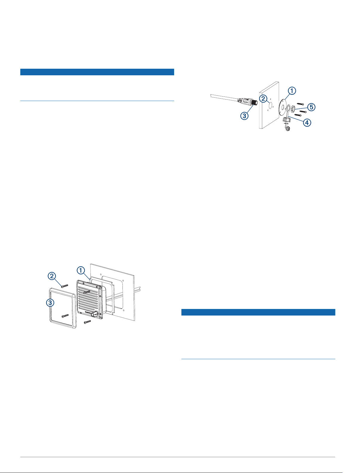
Install the included mounting gasket À on the back of the
11
speaker.
You can use the included hardware to mount the handset
connector from the active speaker on the dashboard or other
mounting surface. If you do not install the active speaker, you
can use the hardware to mount the handset connector from the
included extension cable on the dashboard or other mounting
surface.
Using the mounting plate À as a template, trace the cable
1
hole in the center of the mounting plate and mark the screw
locations.
Set the mounting plate aside.
2
Do not drill through the mounting plate.
Using a 22 mm (7/8 in.) drill bit or hole saw, drill the center
3
cable hole Á in the mounting surface.
Using a 3 mm (1/8 in.) drill bit, drill the pilot holes.
4
Apply marine sealant between the mounting plate and the
5
mounting surface to help seal the holes (optional).
Using the included screws, attach the mounting plate to the
6
mounting surface.
Select an option:
7
• If you installed the active speaker, route the long cable
from the active speaker to the connector mounting
location.
• If you did not install the active speaker, connect the
female end of the included extension cable to the GHS 11
STATION 1 port on the VHF radio, and route the male end
of the extension cable to the connector mounting location.
Feed the connector  through the back of the mounting
8
surface.
Apply marine sealant around the connector in the mounting
9
plate to help seal the hole (optional).
Secure the connector to the mounting plate using the
10
weather cap à and the nut Ä.
GHS 11 Mounting Considerations
Make the necessary wiring connections (Connecting the
12
Active Speaker to the VHF Radio and Handset, page 3).
Place the speaker in the cutout.
13
Secure the speaker to the mounting surface using the
14
included M4 screws Á.
Snap the screw cover  in place.
15
Installing the Handset Connector in the Mounting Surface
Before drilling a hole to mount the handset connector from the
active speaker, you should mount the active speaker and verify
that the cable from the active speaker is long enough to reach
the handset-connector mounting location (Mounting the Active
Speaker, page 2).
If you do not install the active speaker, you must verify that the
included extension cable is long enough to connect to the GHS
11 STATION 1 port on the VHF radio and to the handsetconnector mounting location.
2
NOTICE
This device should be mounted in a location that is not exposed
to extreme temperatures or conditions. The temperature range
for this device is listed in the product specifications. Extended
exposure to temperatures exceeding the specified temperature
range, in storage or operating conditions, may cause device
failure. Extreme-temperature-induced damage and related
consequences are not covered by the warranty.
• You must install the primary handset (connected to the GHS
11 STATION 1 port) in the wheelhouse or an adjacent room,
in accordance with FCC law.
• To avoid interference with a magnetic compass, do not install
the handset closer than 60 cm (23.6 in.) to a compass.
• If you do not install the active speaker, you can use the
included 10 m (32 ft.) extension cable to connect the handset
to the VHF radio. You must select a mounting location for the
handset where you can connect the extension cable to the
handset and to the GHS 11 STATION 1 port on the VHF
radio. If needed, additional extension cables are available
from your Garmin dealer.
• You can use the included screws to mount the handset
connector and the handset cradle mount on your boat. If the
 Loading...