

Garmin VHF 115 AIS Series, VHF 215 AIS Series Installation Instructions Manual
VHF 115/215 AIS SERIES
INSTALLATION
INSTRUCTIONS
Important Safety Information
WARNING
See the Important Safety and Product Information guide in the
product box for product warnings and other important
information.
CAUTION
Always wear safety goggles, ear protection, and a dust mask
when drilling, cutting, or sanding.
NOTICE
When drilling or cutting, always check what is on the opposite
side of the surface.
Registering Your Device
Help us better support you by completing our online registration
today. Keep the original sales receipt, or a photocopy, in a safe
place.
1
Go to garmin.com/express.
2
Sign in to your Garmin® account.
Mounting Considerations
NOTICE
This device should be mounted in a location that is not exposed
to extreme temperatures or conditions. The temperature range
for this device is listed in the product specifications. Extended
exposure to temperatures exceeding the specified temperature
range, in storage or operating conditions, may cause device
failure. Extreme-temperature-induced damage and related
consequences are not covered by the warranty.
When selecting a mounting location, you should observe these
considerations.
• The location should provide optimal viewing as you operate
your boat.
• The location should allow for easy access to all device
interfaces, such as the keypad, touchscreen, and card
reader, if applicable.
• The location must be strong enough to support the weight of
the device and protect it from excessive vibration or shock.
• To avoid interference with a magnetic compass, the device
should not be installed closer to a compass than the
compass-safe distance value listed in the product
specifications.
• The location must allow room for the routing and connection
of all cables.
• The location must not be a flat, horizontal surface. The
location should be in a vertical angle.
The location and viewing angle should be tested before you
install the device. High viewing angles from above and below
the display may result in a poor image.
Antenna Mounting and EME Exposure
WARNING
Radio operators with cardiac pacemakers, life-support
machines, or electrical medical equipment should not be
exposed to excessive radio-frequency (RF) fields, because the
RF field may interfere with the function of their medical
equipment.
CAUTION
This device generates and radiates radio frequency (RF)
electromagnetic energy (EME). Failure to observe these
guidelines may expose people to RF radiation absorption
exceeding the maximum permissible exposure (MPE).
Garmin declares a MPE radius of 2.48 m (97.64 in.) for this
system, which was determined using 5 W output to an omnidirectional, 6 dBi gain antenna. The antenna should be installed
to maintain a distance of 2.48 m (97.64 in.) between the antenna
and all people.
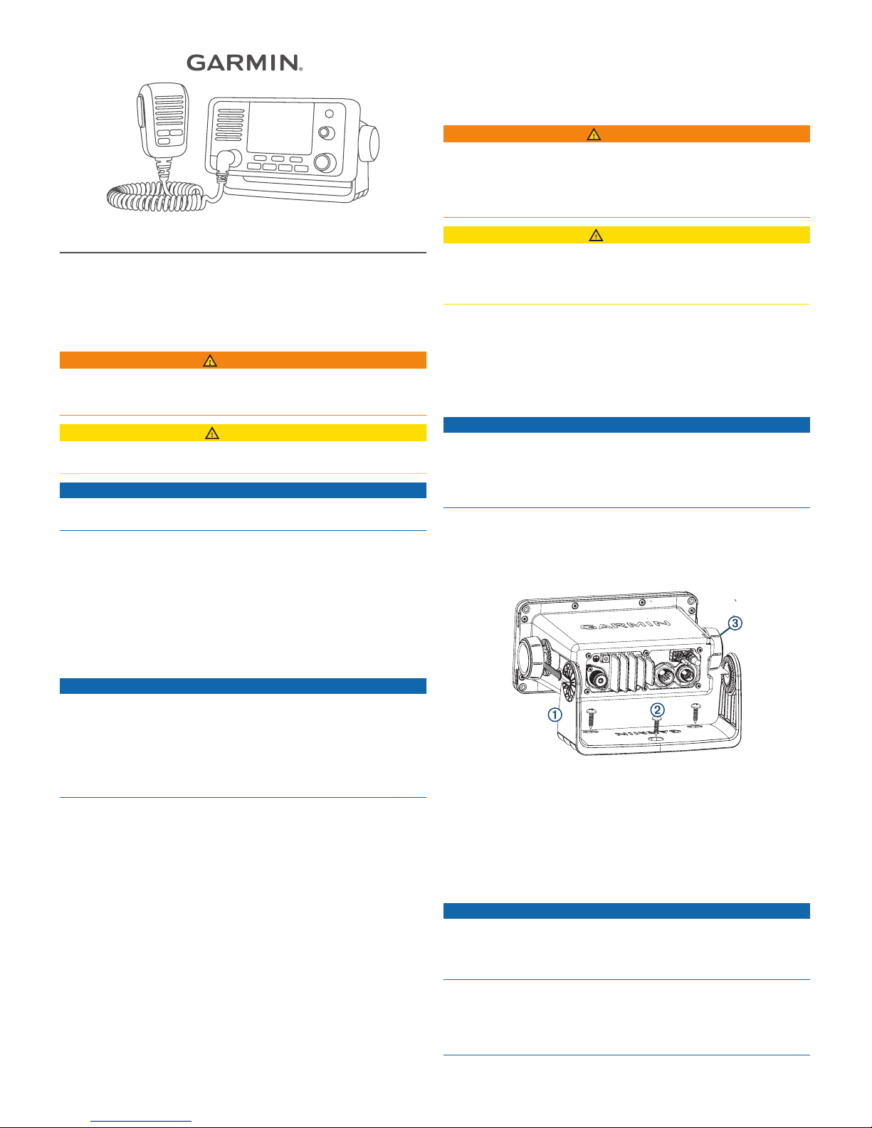
Bail Mounting the Device
NOTICE
If you are mounting the bracket on fiberglass with screws, it is
recommended to use a countersink bit to drill a clearance
counterbore through only the top gel-coat layer. This will help to
avoid cracking in the gel-coat layer when the screws are
tightened.
You can use the included bracket to bail mount the device on a
flat surface.
1
Using the bail-mount bracket À as a template, mark the pilot
holes.
2
Using a 3.5 mm (9/64 in.) drill bit, drill the pilot holes.
3
Using the included screws Á, secure the bail-mount bracket
to the mounting surface.
4
Install the bail-mount knobs  on the sides of the device.
5
Place the device in the bail-mount bracket and tighten the
bail-mount knobs.
Flush Mounting the Device
NOTICE
Be careful when cutting the hole to flush mount the device.
There is only a small amount of clearance between the case and
the mounting holes, and cutting the hole too large could
compromise the stability of the device after it is mounted.
If you are mounting the bracket on fiberglass with screws, it is
recommended to use a countersink bit to drill a clearance
counterbore through only the top gel-coat layer. This will help to
avoid cracking in the gel-coat layer when the screws are
tightened.
September 2018
190-02426-02_0A
The included template and hardware can be used to mount the
device in your dashboard.
1
Trim the template and make sure it fits in the location where
you want to mount the device.
2
Using a 9.5 mm (3/8 in.) drill bit, drill one or more of the holes
inside the corners of the solid line on the template to prepare
the mounting surface for cutting.
3
Using a jigsaw or rotary tool, cut the mounting surface along
the inside of the solid line indicated on the template.
4
Place the device in the cutout to test the fit.
5
If necessary, use a file and sandpaper to refine the size of
the cutout.
6
After the device fits correctly in the cutout, ensure the
mounting holes on the device line up with the pilot holes on
the template.
7
If the mounting holes on the device do not line up, mark the
new pilot-hole locations.
8
Using a 3.5 mm (9/64 in.) drill bit, drill the pilot holes.
9
Remove the template from the mounting surface.
10
If you will not have access to the back of the device after you
mount it, connect all necessary cables to the device before
placing it into the cutout.
11
If necessary, cover unused connectors with the attached
weather caps to prevent corrosion of the metal contacts.
12
Install the foam gasket À on the back of the device.
The pieces of the rubber gasket have adhesive on the back.
Make sure you remove the protective liner before installing
them on the device.
13
Place the device in the cutout.
14
Secure the device to the mounting surface using the included
screws Á.
15
Install the decorative bezel by snapping it in place around the
edges of the device.
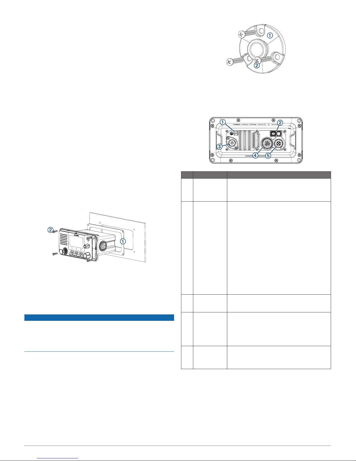
Mounting the Microphone Hanger
NOTICE
If you are mounting the bracket on fiberglass with screws, it is
recommended to use a countersink bit to drill a clearance
counterbore through only the top gel-coat layer. This will help to
avoid cracking in the gel-coat layer when the screws are
tightened.
You can mount the microphone hanger in a convenient location
near the radio.
1
Select a mounting location for the microphone within reach of
the microphone cable.
2
Using the microphone hanger À as a template, mark the pilot
holes.
3
Drill the mounting holes using a 3 mm (1/8 in.) drill bit.
4
Secure the microphone hanger to the mounting surface using
the included screws Á.
Connection Considerations
Item Description Notes
À
Ground
connection
You can use the included grounding screw to
connect the device chassis to water ground, if
needed (Additional Grounding Considerations,
page 2).
Á
Power and
data wiring
harnesses
You must connect the device to a 12 Vdc power
source (Connecting the Wiring Harness to
Power, page 2).
You can connect this device to a NMEA® 0183
device using this wiring harness to share DSC
and GPS information (optional) (NMEA 0183
Device Connections, page 3).
You can connect this device to an external GPS
antenna using this wiring harness (optional)
(Connecting to a Remote GPS Antenna,
page 3).
You can connect this device to a hailer horn
using this wiring harness (optional) (Connecting
to a Hailer Horn or PA Speaker, page 3).
You can connect this device to an external
speaker using this wiring harness (optional)
(Connecting to an External Speaker, page 3).
Â
VHF antenna
connection
You must connect the device to a VHF antenna
(sold separately) (Connecting a VHF Antenna,
page 3).
Ã
Additional
microphone
connector
You can add an additional microphone (sold
separately) or relocate the existing microphone
on a VHF 215 AIS radio (microphone relocation
kit sold separately).
This connector is not available on a VHF 115
radio.
Ä
NMEA 2000
®
connector
You can connect this device to a NMEA 2000
network on your boat to share DSC and GPS
information (optional) (NMEA 2000 Device
Connections, page 3).
Connecting the Wiring Harness to Power
1
Route the wiring harness to the power source and to the
device.
2
Connect the red wire to the positive (+) battery terminal, and
connect the black wire to the negative (-) battery terminal.
Additional Grounding Considerations
This device should not need any additional chassis grounding in
most installation situations. If interference is experienced, the
grounding screw on the housing can be used to connect the
2
 Loading...