

Garmin GXM Series, GXM Installation Instructions Manual
GXM™ Installation Instructions
This antenna provides SiriusXM® weather and radio to your
existing NMEA 2000® network. If you do not have an existing
NMEA 2000 network on your boat, you must install one. For
more information about NMEA 2000, go to www.garmin.com.
Important Safety Information
WARNING
See the Important Safety and Product Information guide in the
product box for product warnings and other important
information.
The weather information provided through this product is
subject to service interruptions and may contain errors,
inaccuracies, or outdated information, and consequently should
not be relied upon exclusively. Always use common sense while
navigating, and check alternate weather information sources
prior to making safety-related decisions. You acknowledge and
agree that you shall be solely responsible for use of the weather
information and all decisions taken with respect to navigating in
weather. Garmin® will not be responsible for any consequences
of using SiriusXM weather information.
CAUTION
Always wear safety goggles, ear protection, and a dust mask
when drilling, cutting, or sanding.
NOTICE
When drilling or cutting, always check what is on the opposite
side of the surface.
Registering Your Device
Help us better support you by completing our online registration
today.
• Go to http://my.garmin.com.
• Keep the original sales receipt, or a photocopy, in a safe
place.
Contacting Garmin Product Support
• Go to www.garmin.com/support and click Contact Support
for in-country support information.
• In the USA, call (913) 397.8200 or (800) 800.1020.
• In the UK, call 0808 2380000.
• In Europe, call +44 (0) 870.8501241.
Loading the New Software on a Memory
Card
The device may contain a software-update memory card. If so,
follow the instructions provided with the card. If a software
update memory card is not included, you must copy the
software update to a memory card.
1
Insert a memory card into the card slot on the computer.
2
Go to www.garmin.com/support/software/marine.html.
3
Select Download next to “Chartplotters with SD card”.
4
Read and agree to the terms.
5
Select Download.
6
Select Run.
7
Select the drive associated with the memory card, and select
Next > Finish.
Updating the Device Software
Before you can update the software, you must obtain a
software-update memory card or load the latest software onto a
memory card.
1
Turn on the chartplotter.
2
Insert the memory card into the card slot.
3
Follow the on-screen instructions.
The software update process takes approximately 2–10
minutes to complete. The device returns to normal operation
when the update process is complete.
NOTE: Do not remove the memory card until the device has
returned to normal operation.
Antenna Mounting Considerations
You can mount the antenna on a flat surface, install it under
fiberglass, or attach it to a standard 1 in. OD, 14 threads per
inch, pipe-threaded pole (not included). You can route the cable
outside of the pole or through the pole. For best performance,
consider these guidelines when selecting the antenna mounting
location.
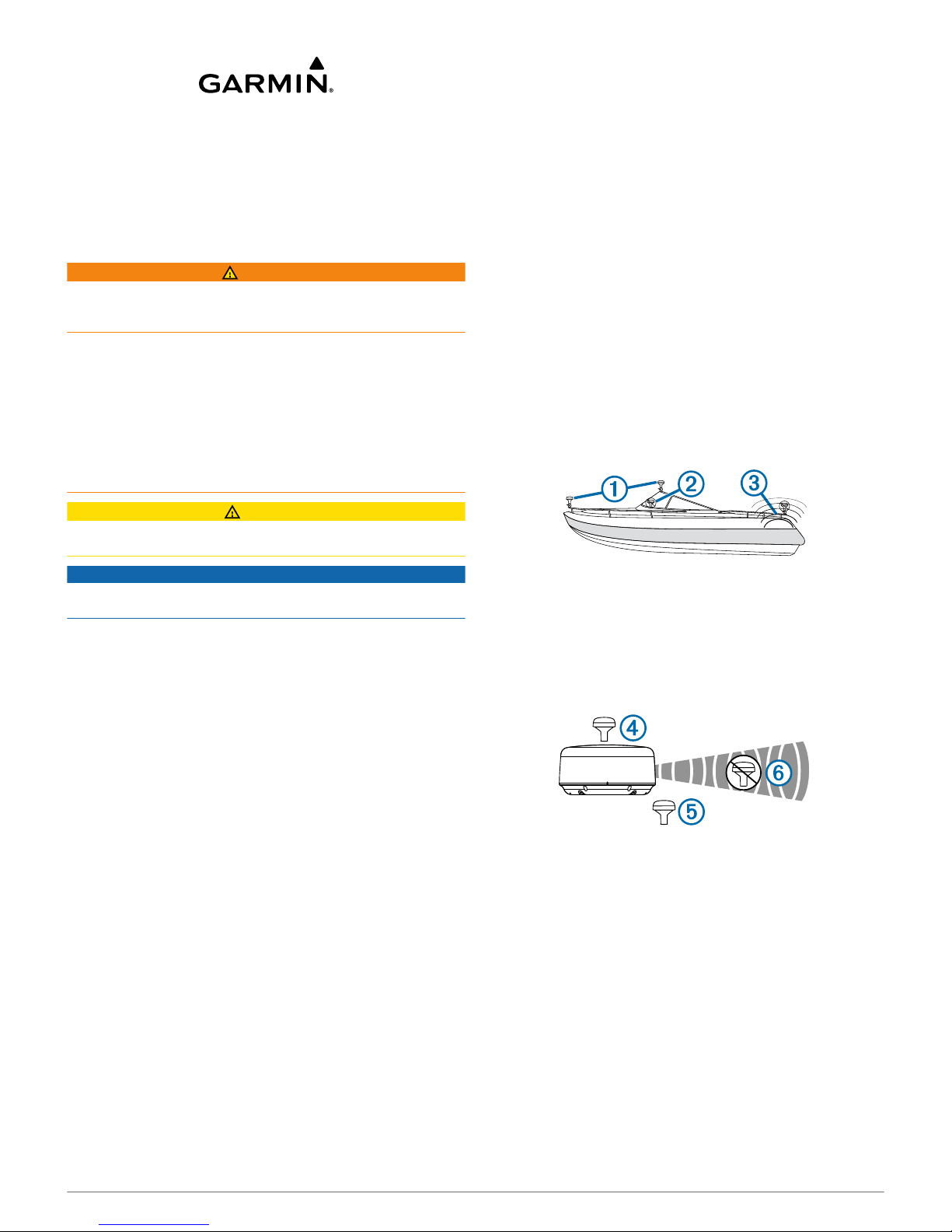
• To ensure the best reception, the antenna should be
mounted in a location that has a clear, unobstructed view of
the sky in all directions À.
• The antenna should not be mounted where it is shaded by
the superstructure of the boat Á, a radome antenna, or the
mast.
• The antenna should not be mounted near the engine or other
sources of Electromagnetic Interference (EMI) Â.
• If a radar is present, the antenna should be mounted above
the path of the radar Ã. If necessary, the antenna may be
mounted below the path of the radar Ä.
• The antenna should not be mounted directly in the path of
the radar Å.
• The antenna should be mounted at least 3 ft. (1 m) away
from (preferably above) the path of a radar beam or a VHF
radio antenna Æ.
March 2014
190-01636-02_0B Printed in Taiwan

Testing the Mounting Location
1
Temporarily secure the antenna in the preferred mounting
location and test it for correct operation.
2
If you experience interference with other electronics, move
the antenna to a different location, and test it again.
3
Repeat steps 1–2 until you observe full or acceptable signal
strength.
4
Permanently mount the antenna.
Surface Mounting the Antenna
NOTICE
If you are mounting the bracket on fiberglass with screws, it is
recommended to use a countersink bit to drill a clearance
counterbore through only the top gel-coat layer. This will help to
avoid any cracking in the gel-coat layer when the screws are
tightened.
Stainless-steel screws may bind when screwed into fiberglass
and overtightened. Garmin recommends applying an anti-seize
lubricant to the screws before installing them.
Before you permanently mount the antenna, you must test the
mounting location for correct operation (Antenna Mounting
Considerations).
1
Using the surface-mount bracket À as your mounting
template, mark the three pilot-hole locations and trace the
cable-hole in the center of the bracket.
2
Set the surface-mount bracket aside.
Do not drill through the bracket.
3
Drill the three 1/8 in. (3.2 mm) pilot holes.
4
Use a 1 in. (25 mm) hole saw to cut the cable hole in the
center.
5
Place the seal pad Á on the bottom of the surface-mount
bracket, aligning the screw holes.
6
Use the included M4 screws to secure the surface-mount
bracket to the mounting surface.
7
Route the cable  through the 1 in. (25 mm) hole and
connect it to the antenna.
8
Verify that the large gasket à is in place on the bottom of the
antenna, place the antenna on the surface-mount bracket,
and twist it clockwise to lock it in place.
9
Secure the antenna to the mounting bracket with the
included M3 set screw Ä.
10
Route the cable away from sources of electronic
interference.
Mounting the Antenna with the Cable Routed
Through the Pole
Before you permanently mount the antenna, you must test the
mounting location for correct operation (Antenna Mounting
Considerations).
1
Position a standard 1 in. OD, 14 threads per inch, pipethreaded pole (not included) in the selected location, and
mark the approximate center of the pole.
2
Drill a hole using a ¾ in. (19 mm) drill bit for the cable to
pass through.
3
Fasten the pole to the boat.
4
Thread the pole-mount adapter onto the pole.
Do not overtighten the adapter.
5
Route the cable through the pole and connect it to the
antenna.
6
Place the antenna on the pole-mount adapter and twist it
clockwise to lock it in place.
7
Secure the antenna to the adapter with the included M3 set
screw À.
8
With the antenna installed on the pole mount, fill the vertical
cable slot Á with a marine sealant (optional).
9
Route the cable away from sources of electronic
interference.
Mounting the Antenna with the Cable Routed Outside
the Pole
Before you permanently mount the antenna, you must test the
mounting location for correct operation (Antenna Mounting
Considerations).
1
Route the cable through the pole-mount adapter À, and
place the cable in the vertical slot Á along the base of the
pole-mount adapter.
2
 Loading...