

Garmin GXM 53 Installation manual
GXM™ 53
Installation Instructions
Important Safety Information
WARNING
The weather information provided through this product is subject
to service interruptions and may contain errors, inaccuracies, or
outdated information, and consequently should not be relied
upon exclusively. Always use common sense while navigating,
and check alternate weather information sources prior to making
safety-related decisions. You acknowledge and agree that you
shall be solely responsible for use of the weather information
and all decisions taken with respect to navigating in weather.
Garmin® will not be responsible for any consequences of using
SiriusXM® weather information.
When connecting the power cable, do not remove the in-line
fuse holder. To prevent the possibility of injury or product
damage caused by fire or overheating, the appropriate fuse
must be in place as indicated in the product specifications. In
addition, connecting the power cable without the appropriate
fuse in place voids the product warranty.
CAUTION
Always wear safety goggles, ear protection, and a dust mask
when drilling, cutting, or sanding.
NOTICE
When drilling or cutting, always check what is on the opposite
side of the surface.
Wait several minutes while the software update process
4
completes.
When prompted, leave the memory card in place and restart
5
the chartplotter manually.
Remove the memory card.
6
NOTE: If the memory card is removed before the device
restarts fully, the software update is not complete.
Loading the New Software on a Memory Card
Insert a memory card into the card slot on the computer.
1
Go to www.garmin.com/support/software/marine.html.
2
Select Download next to GPSMAP Series with SD Card.
3
Read and agree to the terms.
4
Select Download.
5
Select Run.
6
Select the drive associated with the memory card, and select
7
Next > Finish.
Antenna Mounting Considerations
You can mount the antenna on a flat surface or attach it to a
standard 1 in. OD, 14 threads per inch, pipe-threaded pole (not
included). You can route the cable outside of the pole or through
the pole. For best performance, consider these guidelines when
selecting the antenna mounting location.
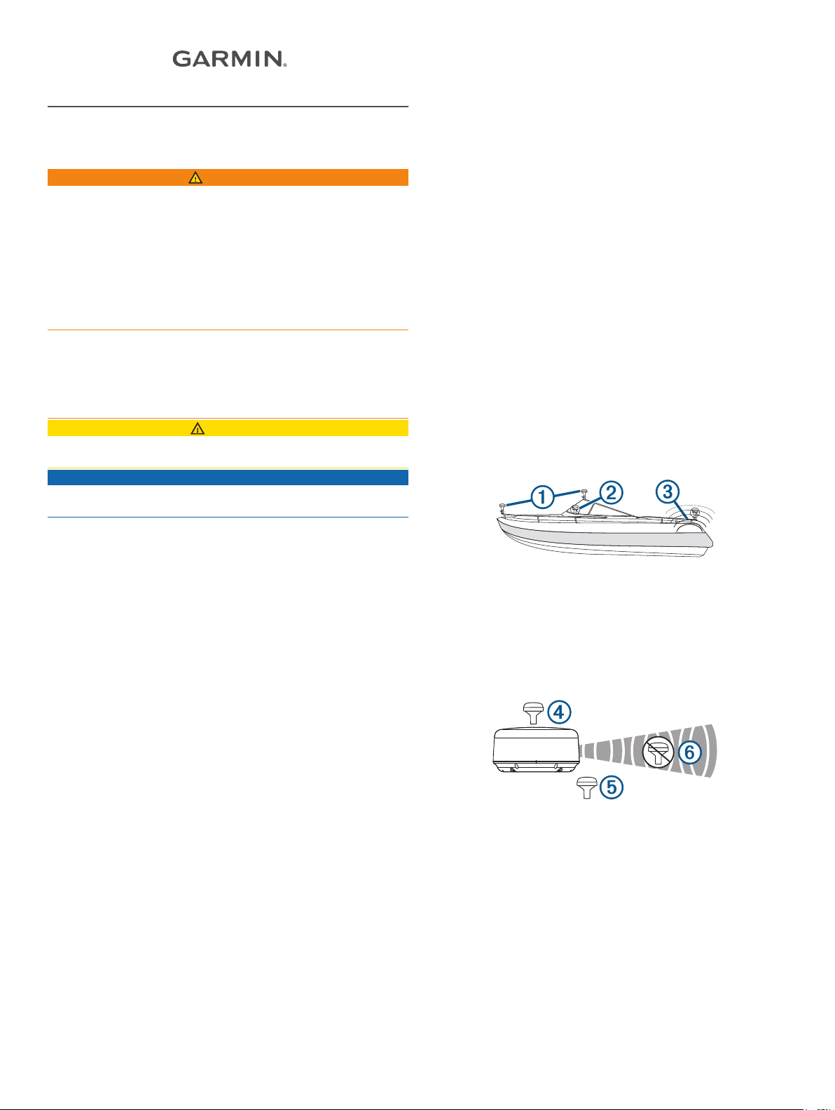
• To ensure the best reception, the antenna should be
mounted in a location that has a clear, unobstructed view of
the sky in all directions À.
Registering Your Device
Help us better support you by completing our online registration
today.
• Go to my.garmin.com.
• Keep the original sales receipt, or a photocopy, in a safe
place.
Contacting Garmin Product Support
• Go to support.garmin.com for in-country support information.
• In the USA, call 913-397-8200 or 1-800-800-1020.
• In the UK, call 0808 238 0000.
• In Europe, call +44 (0) 870 850 1241.
Software Update
You should update the software on all of your Garmin devices
when you install this device.
The software update requires either a Garmin memory card
reader accessory or a Garmin chartplotter connected over the
Garmin Marine Network (sold separately).
Garmin devices support up to a 32 GB memory card, formatted
to FAT32.
Updating the Device Software
Before you can update the software, you must obtain a
software-update memory card or load the latest software onto a
memory card.
Turn on the chartplotter.
1
After the home screen appears, insert the memory card into
2
the card slot.
NOTE: In order for the software update instructions to
appear, the device must be fully booted before the card is
inserted.
Follow the on-screen instructions.
3
• The antenna should not be mounted where it is shaded by
the superstructure of the boat Á, a radome antenna, or the
mast.
• The antenna should not be mounted near the engine or other
sources of Electromagnetic Interference (EMI) Â.
• If a radar is present, the antenna should be mounted above
the path of the radar Ã. If necessary, the antenna may be
mounted below the path of the radar Ä.
• The antenna should not be mounted directly in the path of the
radar Å.
• The antenna should be mounted at least 1 m (3 ft.) away
from (preferably above) the path of a radar beam or a VHF
radio antenna Æ.
December 2016
Printed in Taiwan 190-02153-02_0A
Testing the Mounting Location
Temporarily secure the antenna in the preferred mounting
1
location and test it for correct operation.
If you experience interference with other electronics, move
2
the antenna to a different location, and test it again.
Repeat steps 1–2 until you observe full or acceptable signal
3
strength.
Permanently mount the antenna.
4
Surface Mounting the Antenna
NOTICE
If you are mounting the bracket on fiberglass with screws, it is
recommended to use a countersink bit to drill a clearance
counterbore through only the top gel-coat layer. This will help to
avoid cracking in the gel-coat layer when the screws are
tightened.
Stainless-steel screws may bind when screwed into fiberglass
and overtightened. It is recommended to apply an anti-seize
lubricant on the screws before installing them.
Before you permanently mount the antenna, you must test the
mounting location for correct operation (Antenna Mounting
Considerations, page 1).
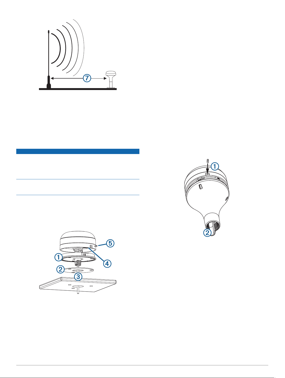
Using the surface-mount bracket À as your mounting
1
template, mark the three pilot-hole locations and trace the
cable-hole in the center of the bracket.
Verify the large gasket à is in place on the bottom of the
8
antenna, place the antenna on the surface-mount bracket,
and twist it clockwise to lock it in place.
Secure the antenna to the mounting bracket with the included
9
M3 screw Ä.
Route the cable away from sources of electronic interference.
10
Mounting the Antenna with the Cable Routed Through the Pole
Before you permanently mount the antenna, you must test the
mounting location for correct operation ( (Antenna Mounting
Considerations, page 1)).
Position a standard 1 in. OD, 14 threads per inch, pipe-
1
threaded pole (not included) in the selected location, and
mark the approximate center of the pole.
Drill a hole using a 19 mm (3/4 in.) drill bit for the cable to
2
pass through.
Fasten the pole to the boat.
3
Thread the pole-mount adapter onto the pole.
4
Do not overtighten the adapter.
Route the cable through the pole and connect it to the
5
antenna.
Place the antenna on the pole-mount adapter and twist it
6
clockwise to lock it in place.
Secure the antenna to the adapter with the included M3 set
7
screw À.
Set the surface-mount bracket aside.
2
Do not drill through the bracket.
Drill the three 3.2 mm (1/8 in.) pilot holes.
3
Drill the 19 mm (3/4 in.) cable hole in the center.
4
Place the seal pad Á on the bottom of the surface-mount
5
bracket, aligning the screw holes.
Use the included M4 screws to secure the surface-mount
6
bracket to the mounting surface.
Route the cable  through the center hole and connect it to
7
the antenna.
2
With the antenna installed on the pole mount, fill the vertical
8
cable slot Á with a marine sealant (optional).
Route the cable away from sources of electronic interference.
9
Mounting the Antenna with the Cable Routed Outside the Pole
Before you permanently mount the antenna, you must test the
mounting location for correct operation ( (Antenna Mounting
Considerations, page 1)).
Route the cable through the pole-mount adapter À, and
1
place the cable in the vertical slot Á along the base of the
pole-mount adapter.
 Loading...