

Garmin gWind Race Transducer Installation Instructions
gWind Race™ Installation Instructions................................................................................................ 2
TA-2013/1725
TA-2013/2433
Instructions d'installation du gWind Race™.........................................................................................5
gWind Race™ Istruzioni di installazione..............................................................................................8
gWind Race™ – Installationsanweisungen........................................................................................11
Instrucciones de instalación de gWind Race™..................................................................................14
Instruções de instalação do gWind Race™....................................................................................... 17
gWind Race™ installatie-instructies.................................................................................................. 20
gWind Race™ Installationsvejledning................................................................................................23
gWind Race™ asennusohjeet........................................................................................................... 26
Installeringsinstruksjoner for gWind Race™...................................................................................... 29
gWind Race™ – installationsinstruktioner......................................................................................... 32
Instrukcja instalacji urządzenia gWind Race™.................................................................................. 35
Pokyny pro instalaci zařízení gWind Race™..................................................................................... 38
Upute za montažu uređaja gWind Race™.........................................................................................41
gWind Race™ 安装说明.................................................................................................................... 44
®
, the Garmin logo, and Nexus® are trademarks of Garmin Ltd. or its subsidiaries, registered in the USA and other countries. gWind Race™, NexusRace™, GND™, and GMI™ are trademarks of Garmin Ltd.
Garmin
or its subsidiaries. These trademarks may not be used without the express permission of Garmin.
NMEA 2000® and the NMEA 2000 logo are registered trademarks of the National Marine Electronics Association.
February 2015 190-01723-97_0BPrinted in Taiwan
gWind Race™ Installation Instructions
This wind transducer provides wind speed and wind angle
information to a NMEA 2000® network on your boat. A Garmin
GND™ 10 must be used to send data from this device to a NMEA
2000 network.
Important Safety Information
WARNING
See the Important Safety and Product Information guide in the
product box for product warnings and other important
information.
CAUTION
Always wear safety goggles, ear protection, and a dust mask
when drilling, cutting, or sanding.
Use caution when working from heights.
Registering Your Device
Help us better support you by completing our online registration
today.
• Go to http://my.garmin.com.
• Keep the original sales receipt, or a photocopy, in a safe
place.
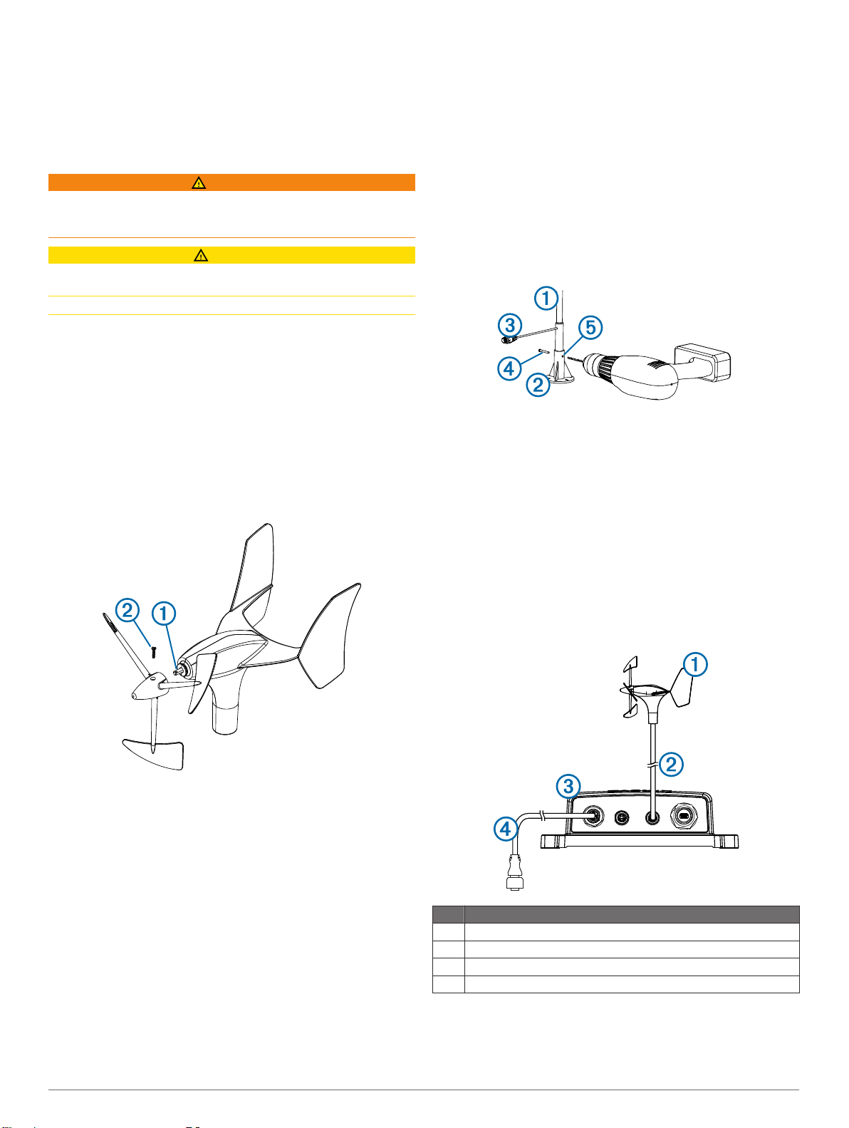
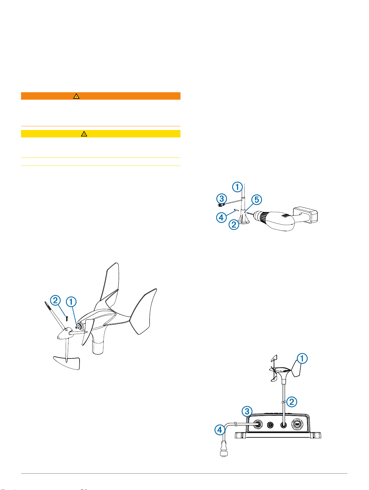
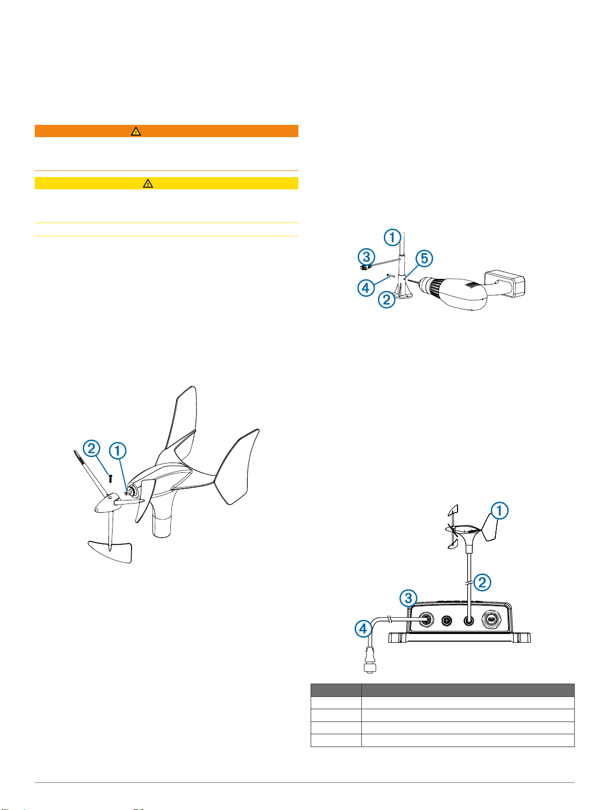
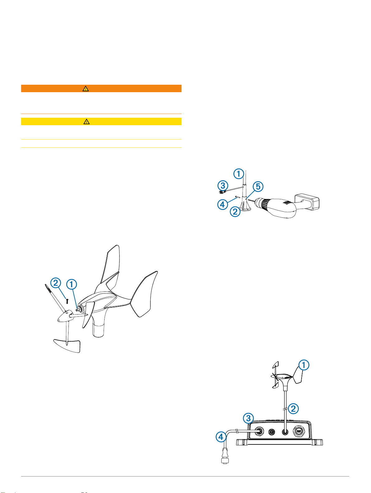
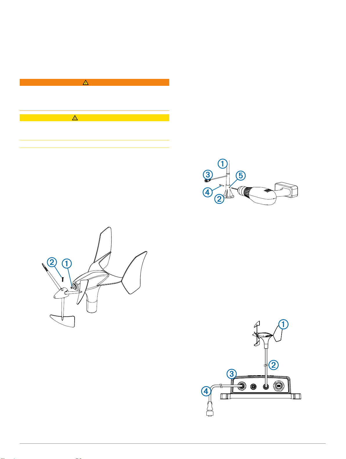
Installing the Propeller
Ensure the shaft À lines up correctly with the slot on the
1
propeller.
The socket on the propeller fits only one way on the shaft.
®
Installing the Mounting Bracket
The included bracket can be used to mount the device if you do
not have a pole mount pre-installed on your mast.
Using the mounting bracket as a template, mark the pilot hole
1
locations.
Using a 4.5 mm (11/64 in.) bit, drill the pilot holes.
2
Fasten the mounting bracket to the surface using the
3
included screws.
Securing the Device in the Mounting Bracket
The included bracket can be used to mount the device if you do
not have a pole mount pre-installed on your mast.
Slide the pole À into the mounting bracket Á, and turn it until
1
the cable  points in the preferred direction.
Holding the pole securely, use a 5.5 mm (7/32 in.) bit to drill a
2
hole halfway through the pole, drilling through the hole in one
side of the mounting bracket.
Insert the included hex screw à through the hole you drilled
3
in step 2.
This holds the pole in place while you drill another hole.
Drill through the other half of the pole by drilling through the
4
hole on the other side of the mounting bracket Ä.
Push the hex screw completely through both holes and
5
secure it using the included lock nut.
Press on the propeller until it is seated on the device.
2
Install the set screw Á to hold the propeller securely to the
3
device.
Mounting Considerations
When selecting a mounting location for the wind transducer,
observe these considerations.
• The wind transducer can be installed in either a pre-existing
pole mount on your mast, or in the included mounting
bracket.
• If you are installing the included mounting bracket, it should
be mounted on a horizontal surface on the mast head.
• If there is not a horizontal surface on the mast head, an
appropriate shim must be added to create a horizontal
surface.
• You must configure the wind-angle offset to receive accurate
wind-angle data by following the directions in these
installation instructions.
Connection Considerations
This device must connect to a Garmin GND 10 to communicate
with the NMEA 2000 network on your boat.
Item Description
gWind™ device
À
Included Nexus® mast cable with a field-installable connector
Á
GND 10
Â
NMEA 2000 network
Ã
Nexus Connection Considerations
If you change from a Nexus wind sensor to the gWind sensor,
you must move the mast cable from the wind port to the network
port on the Nexus server on pins 5, 6, 7, and 8. The network
2 Installation Instructions
server is NX2, and the classic server is BUS. See the Nexus
device manual for more information.
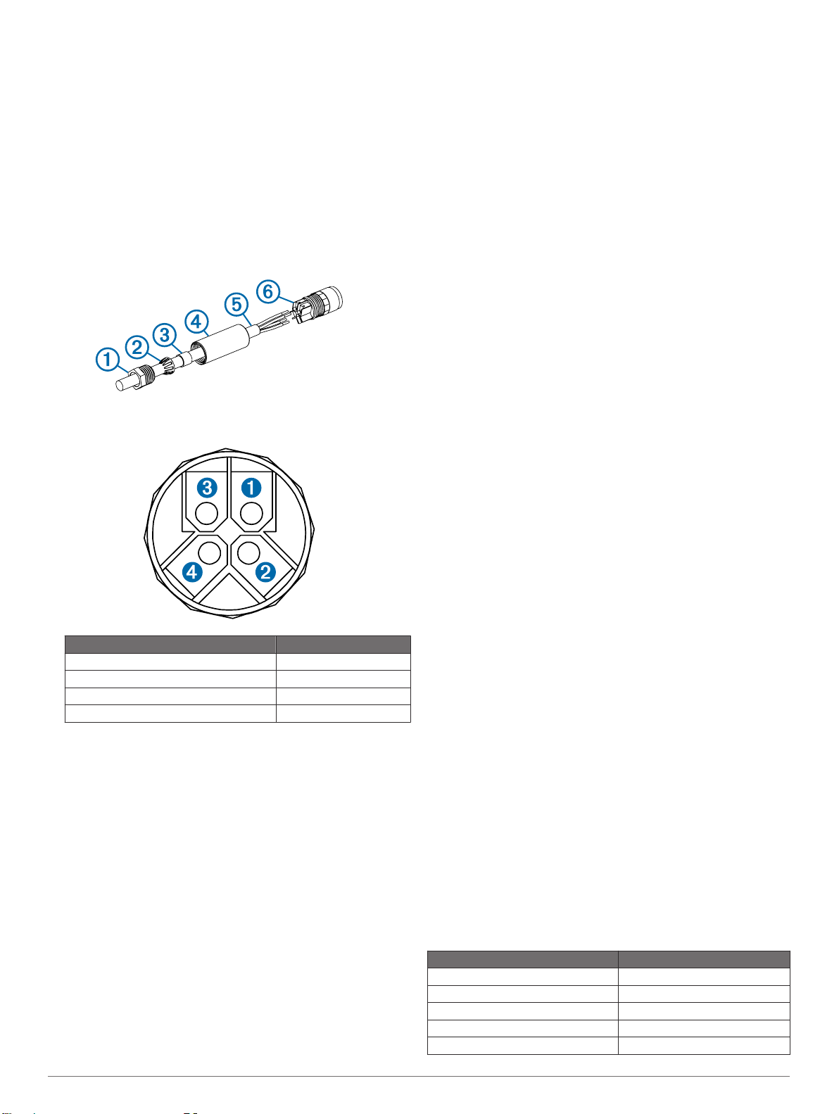
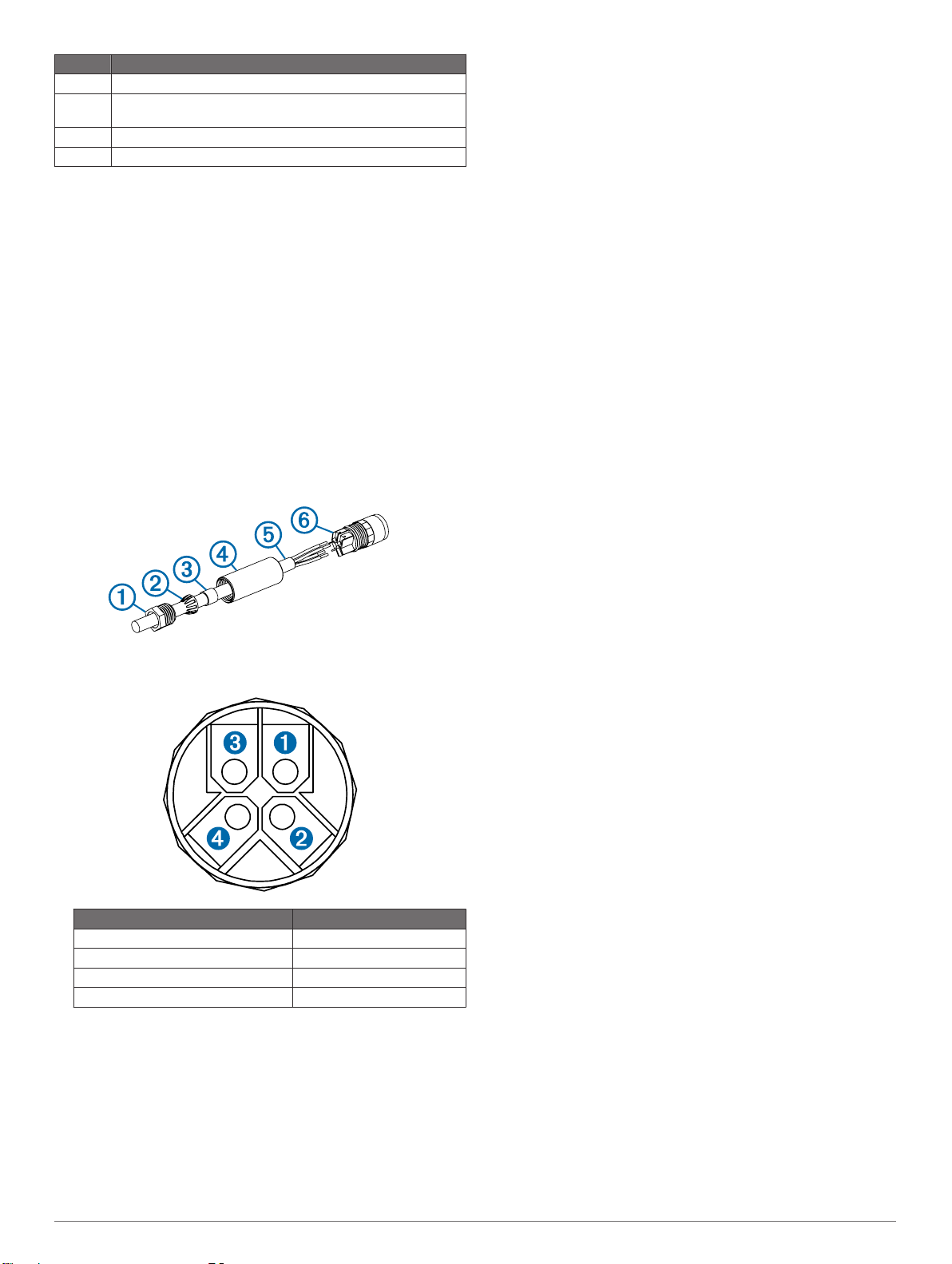
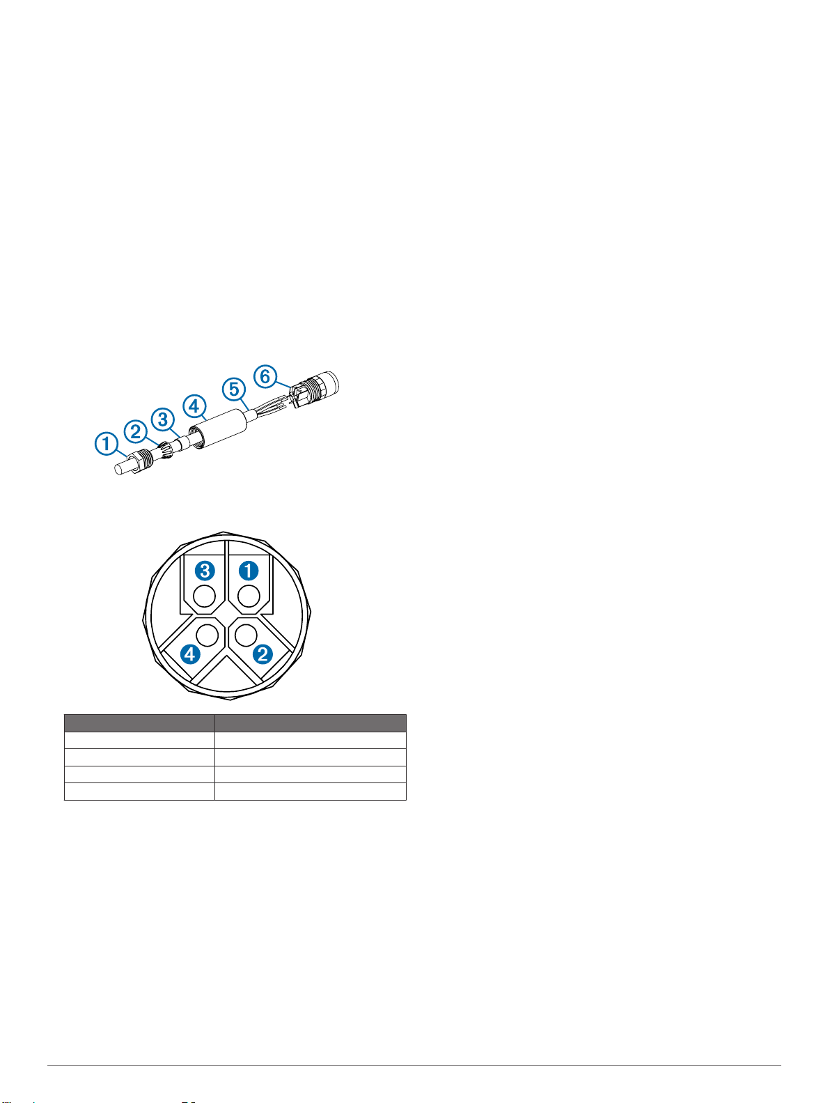
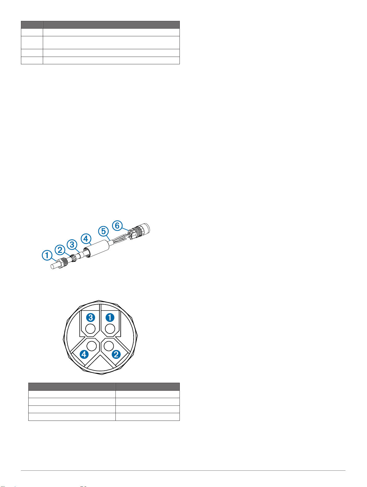
Installing the Nexus Field-Installable Connector
You must use the included field-installable connector to create
the appropriate cable length for your installation.
Connect the finished end of the included bulk cable to the
1
wind transducer on the mast.
Route the bare end of the cable to the location of the
2
GND 10.
Leaving an appropriate amount of slack, cut the bare end of
3
the wire, remove the casing, and strip the individual wires.
Disassemble the field-installable connector and place the
4
pressing screw À, pinch ring Á, seal Â, and sleeve à on the
cable Ä.
Using the screws on the back of the connector Å, connect
5
each wire to the appropriate terminal.
Terminal Number Wire Color
Ê
Ë
Ì
Í
Screw the sleeve onto the connector.
6
Slide the seal into the sleeve and slide the pinch ring over the
7
seal.
Screw the pressing screw into the sleeve to complete the
8
assembly of the field-installable connector.
Connect the field-installable connector to either NEXUS port
9
on the GND 10.
Green
Yellow
Bare wire
White
Configuring the Wind Transducer
Before you can configure the wind transducer, it must be
connected through a GND 10 to a NMEA 2000 network with a
Garmin marine instrument, such as a GMI™ 20. Refer to the
marine instrument owner's manual for more information on
configuring NMEA 2000 devices.
On the marine instrument, go to the NMEA 2000 settings.
1
Select the name of the device (GND 10) to configure.
2
Adjusting the Orientation
You should adjust this setting if the sensor does not face the
exact front of the boat.
On the marine instrument, from the NMEA 2000 settings,
1
select the device name (GND 10).
Select Wind Angle Offset.
2
Based on the direction in which the sensor is facing in
3
relation to the exact center of the front of the boat, select the
angle in degrees to adjust for the difference in orientation.
The angle is configured clockwise around the mast of the
boat, from the exact center of the front of the boat. For
example, 90 degrees is starboard, and 270 degrees is port.
Select Done.
4
Adjusting the Wind Angle Filter
You should adjust this setting to change the responsiveness of
the display to changes in the wind direction.
On the marine instrument, from the NMEA 2000 settings,
1
select the device name (GND 10).
Select Wind Angle Filter.
2
Select an option:
3
• Select Off to turn off the filter and make the display the
most responsive to changes in the wind angle.
• Select On and adjust the value. Select a higher number to
increase the responsiveness of the display to changes in
the wind angle, or select a lower number to decrease the
responsiveness.
• Select Auto to automatically adjust the filter settings
based on wind conditions.
Select Done.
4
Adjusting the Wind Speed Filter
You should adjust this setting to change the responsiveness of
the display to changes in the wind speed.
On the marine instrument, from the NMEA 2000 settings,
1
select the device name (GND 10).
Select Wind Speed Filter.
2
Select an option:
3
• Select Off to turn off the filter and make the display the
most responsive to changes in the wind speed.
• Select On and adjust the value. Select a higher number to
increase the responsiveness of the display to changes in
the wind speed, or select a lower number to decrease the
responsiveness.
• Select Auto to automatically adjust the filter settings
based on wind conditions.
Select Done.
4
Advanced Calibration
Advanced calibration tools are available for this device using a
connected PC running the NexusRace™ software. You can
download the software from www.garmin.com. You must
connect the PC to the GND 10. For more information, see the
GND 10 Installation Instructions.
Maintenance and Storage
• If needed, use a mild soap solution to clean the wind
transducer, and rinse it with water. Do not use detergents or
high-pressure water.
• It is recommended to remove the wind transducer and store it
in a dry location if it will not be used for long periods of time.
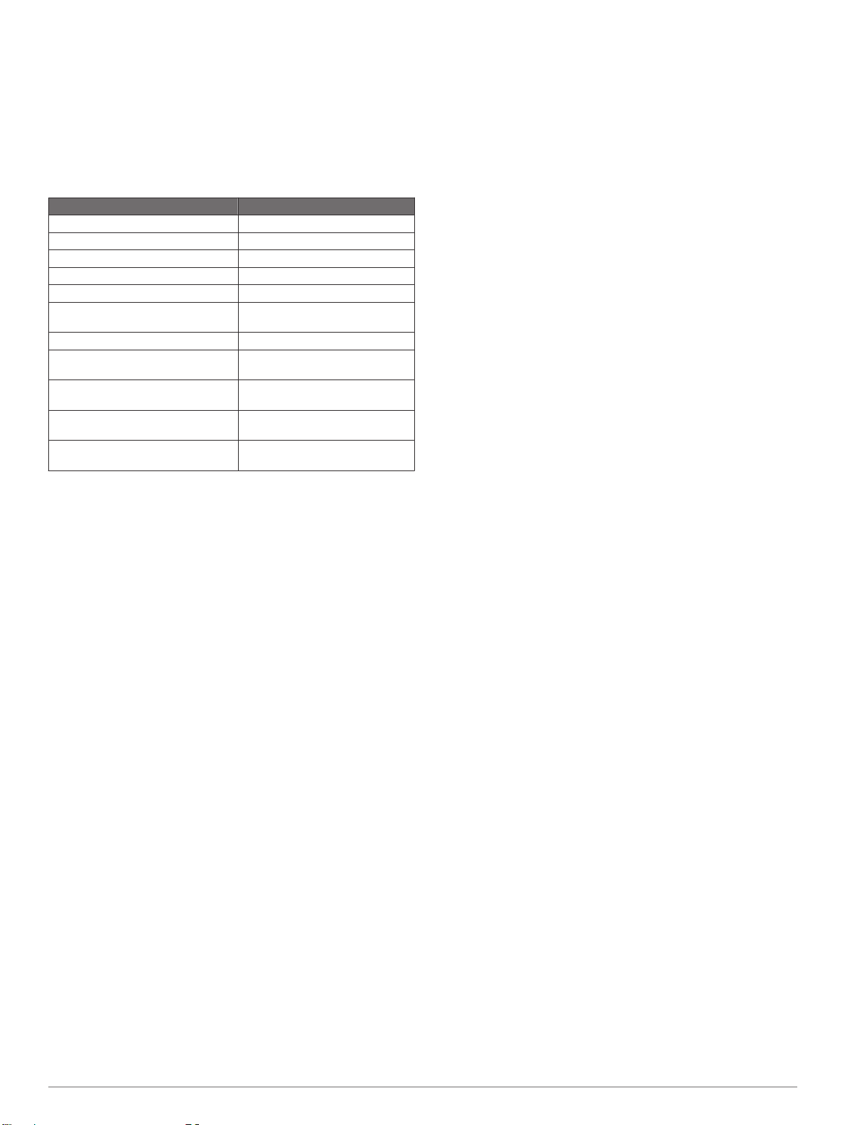
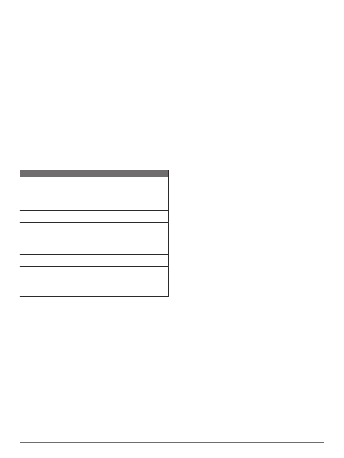
Specifications
Specification Value
Dimensions (H) 1.18 m (46.46 in.)
Weight 320 g (11.29 oz.)
Cable length 25 m (82 ft.)
Operating temperature From -15° to 70°C (5° to 158°F)
Storage temperature From -20° to 80°C (-4° to 176°F)
Installation Instructions 3

Specification Value
Water resistance rating IEC 60529 IPX-6 (protected
Power usage (wind transducer) 0.33 W
Power usage (wind transducer and
GND 10)
Typical current draw at 12 VDC
(wind transducer)
Typical current draw at 12 VDC
(wind transducer and GND 10)
Wind speed range From 0.8 to 90 knots (From 0.4
against heavy seas)
0.85 W
28 mA
71 mA
to 50 m/s)
4 Installation Instructions
Instructions d'installation du gWind
Race
Cette girouette fournit des informations de vitesse et d'angle du
vent à un réseau NMEA 2000 sur votre bateau. Un appareil
Garmin GND 10 doit être utilisé pour envoyer des données de
cet appareil à un réseau NMEA 2000.
Informations importantes relatives à la sécurité
AVERTISSEMENT
Consultez le guide Informations importantes sur le produit et la
sécurité inclus dans l'emballage du produit pour prendre
connaissance des avertissements et autres informations
importantes sur le produit.
ATTENTION
Portez toujours des lunettes de protection, un équipement
antibruit et un masque anti-poussière lorsque vous percez,
coupez ou poncez.
Faites attention lorsque vous travaillez en hauteur.
Enregistrement de l'appareil
Aidez-nous à mieux vous servir en remplissant dès aujourd'hui
notre formulaire d'enregistrement en ligne.
• Rendez-vous sur le site http://my.garmin.com.
• Conservez en lieu sûr l'original de la facture ou une
photocopie.
™
• Vous devez configurer le décalage de l'angle du vent pour
recevoir des données précises sur l'angle du vent. Pour ce
faire, suivez ces instructions d'installation.
Installation du support de montage
Vous pouvez utiliser le support de montage fourni pour monter
l'appareil si aucun montage sur rotule n'est pré-installé sur votre
mât.
En utilisant le support de montage comme modèle, marquez
1
l'emplacement des trous d'implantation.
A l'aide d'un foret de 4,5 mm (11/64 po), percez les trous
2
d'implantation.
Fixez le support de montage au support à l'aide des vis
3
fournies.
Fixation de l'appareil dans le support de montage
Vous pouvez utiliser le support de montage fourni pour monter
l'appareil si aucun montage sur rotule n'est pré-installé sur votre
mât.
Faites coulisser la rotule À dans le support de montage Á et
1
tournez-la jusqu'à ce que le câble  soit dirigé dans la
direction de votre choix.
Installation de l'hélice
Assurez-vous que la tige À s'aligne sur la fente située sur
1
l'hélice.
La cavité située sur l'hélice ne s'adapte à la tige que dans un
sens.
Appuyez sur l'hélice jusqu'à ce qu'elle soit en place dans
2
l'appareil.
Installez la vis Á pour fixer solidement l'hélice à l'appareil.
3
En tenant la rotule fermement, utilisez un foret de 5,5 mm
2
(7/32 po) pour percer un trou à mi-chemin à travers la rotule.
Percez dans le trou situé sur l'un des côtés du support de
montage.
Insérez la vis Allen fournie à à travers le trou que vous avez
3
percé à l'étape 2.
Cela vous permettra de tenir la rotule en place pendant que
vous percez un autre trou.
Percez à travers l'autre moitié de la rotule. Percez dans le
4
trou situé de l'autre côté du support de montage Ä.
Enfoncez à fond la vis Allen à travers les deux trous et fixez-
5
la à l'aide du contre-écrou fourni.
Considérations relatives à la connexion
Cet appareil doit se connecter à un Garmin GND 10 pour
communiquer avec le réseau NMEA 2000 sur votre bateau.
Considérations relatives au montage
Lorsque vous choisissez un emplacement de montage pour la
girouette, tenez compte des considérations suivantes.
• La girouette anémomètre doit être installée dans une rotule
préexistante sur le mât, ou dans le support de fixation fourni.
• Si vous installez le support de fixation fourni, il doit être
monté sur un support horizontal en haut du mât.
• En l'absence de support horizontal en haut du mât, une cale
appropriée doit être ajoutée afin de pallier le problème.
Instructions d'installation 5
Elément Description
À
Á
Â
Ã
Appareil gWind
Câble pour mât Nexus fourni avec connecteur installable sur
site
GND 10
Réseau NMEA 2000
Considérations relatives à la connexion Nexus
Si vous passez d'une girouette anémomètre Nexus au capteur
gWind, vous devez débrancher le câble pour mât du port de la
girouette et le brancher au port réseau du serveur Nexus sur les
broches 5, 6, 7 et 8. Le serveur réseau est NX2 et le serveur
classique est BUS. Pour plus d'informations, reportez-vous au
manuel de l'appareil Nexus.
Installation du connecteur démontable Nexus
Vous devez utiliser le connecteur démontable fourni pour créer
une longueur de câble adaptée à votre installation.
Connectez l'extrémité du câble à la girouette.
1
Acheminez l'extrémité dénudée du câble à l'emplacement de
2
l'appareil GND 10.
En laissant suffisamment de mou, découpez l'extrémité
3
dénudée du fil, retirez le cache et isolez chacun des fils.
Désassemblez le connecteur démontable et placez la vis de
4
serrage À, la bague de serrage Á, le joint en caoutchouc
et le manchon à sur le câble Ä.
A l'aide des vis sur l'arrière du connecteur Å, reliez chaque fil
5
à la borne appropriée.
Numéro de borne Couleur du fil
Ê
Ë
Ì
Í
Vissez le manchon au connecteur.
6
Faites glisser le joint en caoutchouc dans le manchon et la
7
bague de serrage au-dessus du joint en caoutchouc.
Vissez la vis de serrage dans le manchon pour terminer
8
l'assemblage du connecteur démontable.
Branchez le connecteur démontable à l'un des ports NEXUS
9
de l'appareil GND 10.
Vert
Jaune
Fil dénudé
Blanc
Â
Configuration de la sonde de vent
Avant de pouvoir configurer la girouette, elle doit être connectée
via un appareil GND 10 à un réseau NMEA 2000 avec un
instrument de navigation Garmin tel qu'un GMI 20. Pour en
savoir plus, consultez le manuel d'utilisation de l'instrument de
navigation sur la configuration des appareils NMEA 2000.
Sur l'instrument de navigation, allez dans les paramètres
1
NMEA 2000.
Sélectionnez le nom de l'appareil (GND 10) à configurer.
2
Réglage de l'orientation
Réglez ce paramètre si le capteur n'est pas exactement en face
de la proue.
Sur l'instrument de navigation, dans les paramètres NMEA
1
2000, sélectionnez le nom de l'appareil (GND 10).
Sélectionnez Déviation de l'angle du vent.
2
Suivant la direction dans laquelle le capteur est tourné par
3
rapport au centre exact de la proue, sélectionnez l'angle en
degrés pour compenser la différence d'orientation.
L'angle est axé dans le sens horaire autour du mât du
bateau, à partir de l'axe exact de la proue du bateau. Par
exemple, 90 degrés est à tribord et 270 degrés à bâbord.
Sélectionnez Terminé.
4
Réglage du filtre d'angle du vent
Réglez ce paramètre pour modifier la réactivité de l'écran face
aux changements de direction du vent.
Sur l'instrument de navigation, dans les paramètres NMEA
1
2000, sélectionnez le nom de l'appareil (GND 10).
Sélectionnez Filtre de l'angle du vent.
2
Sélectionnez une option :
3
• Sélectionnez Désactivé pour désactiver le filtre et avoir
un écran le plus réactif possible face aux changements
d'angle du vent.
• Sélectionnez Activé et réglez la valeur. Choisissez une
valeur plus élevée pour augmenter la réactivité de l'écran
aux changements d'angle du vent ou une valeur plus
faible pour la diminuer.
• Sélectionnez Automatique pour régler automatiquement
les paramètres du filtre suivant les conditions de vent.
Sélectionnez Terminé.
4
Réglage du filtre de vitesse du vent
Réglez ce paramètre pour modifier la réactivité de l'écran face
aux changements de vitesse du vent.
Sur l'instrument de navigation, dans les paramètres NMEA
1
2000, sélectionnez le nom de l'appareil (GND 10).
Sélectionnez Filtre de la vitesse du vent.
2
Sélectionnez une option :
3
• Sélectionnez Désactivé pour désactiver le filtre et avoir
un écran le plus réactif possible face aux changements de
vitesse du vent.
• Sélectionnez Activé et réglez la valeur. Choisissez une
valeur plus élevée pour augmenter la réactivité de l'écran
aux changements de vitesse du vent ou une valeur plus
faible pour la diminuer.
• Sélectionnez Automatique pour régler automatiquement
les paramètres du filtre suivant les conditions de vent.
Sélectionnez Terminé.
4
Etalonnage avancé
Des outils d'étalonnage avancé sont disponibles pour cet
appareil. Il suffit d'utiliser un ordinateur connecté disposant du
logiciel NexusRace. Vous pouvez télécharger ce logiciel à
l'adresse www.garmin.com. Vous devez connecter l'ordinateur à
l'appareil GND 10. Pour en savoir plus, consultez les
Instructions d'installation du GND 10.
6 Instructions d'installation
Maintenance et stockage
• Au besoin, utilisez une solution savonneuse douce pour
nettoyer la girouette et rincez-la à l'eau claire. N'utilisez pas
de détergents ni d'eau à haute pression.
• Il est recommandé de retirer la girouette et de la stocker dans
un endroit sec si vous avez prévu de ne pas l'utiliser pendant
une période de temps prolongée.
Caractéristiques techniques
Caractéristique Valeur
Dimensions (H) 1,18 m (46,46 po)
Poids 320 g (11,29 onces)
Longueur du câble 25 m (82 pieds)
Température de fonctionnement De -15 à 70 °C (de 5 à 158 °F)
Température de stockage De -20 à 80 °C (de -4 à 176 °F)
Degré de résistance à l'eau IEC 60529 IPX-6 (protection
Consommation (anémomètre) 0,33 W
Consommation (anémomètre et
GND 10)
Intensité typique à 12 V c.c.
(anémomètre)
Intensité typique à 12 V c.c.
(anémomètre et GND 10)
Plage de vitesse du vent Entre 0,8 et 90 nœuds (entre 0,4
contre les paquets de mer)
0,85 W
28 mA
71 mA
et 50 m/s)
Instructions d'installation 7
gWind Race™ Istruzioni di installazione
Questo trasduttore del vento fornisce i dati di velocità e
direzione del vento a una rete NMEA 2000. Utilizzare Garmin
GND 10 per inviare i dati da questo dispositivo a una rete NMEA
2000.
Informazioni importanti sulla sicurezza
ATTENZIONE
Per avvisi sul prodotto e altre informazioni importanti, consultare
la guida Informazioni importanti sulla sicurezza e sul prodotto
inclusa nella confezione.
AVVISO
Durante le operazioni di foratura, taglio o carteggiatura,
indossare degli occhiali protettivi, una maschera antipolvere e
un'adeguata protezione per l'udito.
Prestare attenzione quando si lavora ad altezze considerevoli.
Registrazione del dispositivo
Per un'assistenza completa, eseguire subito la registrazione
online.
• Visitare il sito Web http://my.garmin.com.
• Conservare in un luogo sicuro la ricevuta di acquisto originale
o una fotocopia.
Installazione dell'anemometro
Accertarsi che il perno À sia allineato correttamente con
1
l'innesto posto nell'anemometro.
È possibile inserire il perno nell'anemometro in un solo modo.
Installazione della staffa di montaggio
Il trasduttore del vento può essere installato sia con la staffa in
dotazione che senza.
Utilizzando la staffa di montaggio come dima,
1
contrassegnare la posizione dei fori di riferimento.
Con una punta da 4,5 mm (11/64 poll.), praticare i fori di
2
riferimento.
Fissare la staffa di montaggio alla superficie utilizzando le viti
3
in dotazione.
Installazione del trasduttore con la staffa di montaggio
Il trasduttore del vento può essere installato sia con la staffa in
dotazione che senza.
Far scorrere l'asta À nella staffa di montaggio Á e ruotarla
1
finché il cavo  non punta verso la direzione desiderata.
Tenendo saldamente l'asta, utilizzare una punta da trapano
2
da 5,5 mm (7/32 poll.) per praticare un foro a metà sull'asta
dal foro su un lato della staffa di montaggio.
Inserire la vite esagonale in dotazione à nel foro praticato nel
3
passo 2.
Questa operazione mantiene l'asta in posizione mentre si
pratica un altro foro.
Forare l'altra metà dell'asta dal foro sull'altro lato della staffa
4
di montaggio Ä.
Inserire completamente la vite esagonale in entrambi i fori e
5
fissarla mediante il dato di blocco in dotazione.
Premere l'anemometro fino a quando non si blocca in
2
posizione.
Installare le viti Á per fissare saldamente l'anemometro.
3
Informazioni sull'installazione
Selezionare la posizione di installazione del trasduttore del
vento tenendo presente quanto segue.
• Il trasduttore del vento può essere installato senza supporto
(spigot) oppure con la sua staffa in dotazione.
• Se si adopera la staffa in dotazione, posizionarla in
orizzontale sulla testa dell'albero.
• Nel caso non fosse possibile, aggiungere uno spessore
appropriato per creare un piano di appoggio orizzontale.
• Configurare l'offset del sensore del vento seguendo le
indicazioni fornite nelle istruzioni di installazione.
Informazioni sul collegamento
Questo dispositivo deve essere collegato a un Garmin GND 10
per comunicare con la rete NMEA 2000.
Elemento Descrizione
À
Á
Â
Ã
Dispositivo gWind
Cavo testa d'albero Nexus e connettore inclusi
GND 10
Rete NMEA 2000
8 Istruzioni di installazione
Informazioni sul collegamento di Nexus
Se si passa da un sensore vento Nexus al sensore gWind, è
necessario spostare il cavo testa d'albero dalla porta vento alla
porta rete sul server Nexus sui pin 5, 6, 7 e 8. Il server di rete è
NX2 e il server classico è BUS. Per ulteriori informazioni,
consultare il manuale del dispositivo Nexus.
Installazione del connettore Nexus installabile sul campo
Utilizzare il connettore installabile sul campo in dotazione per
creare la lunghezza del cavo appropriata per l'installazione.
Collegare l'estremità rifinita del cavo non pretagliato in
1
dotazione al trasduttore del vento sull'albero.
Passare l'estremità priva di rivestimento del cavo nella
2
posizione del GND 10.
Lasciando il cavo allentato, tagliare l'estremità priva di
3
protezione, rimuovere la parte esterna e il rivestimento dai
singoli cavi.
Disassemblare il connettore installabile sul campo e
4
posizionare la vite di pressione À, l'anello di fermo Á, la
guarnizione  e il manicotto à sul cavo Ä.
Utilizzando le viti sulla parte posteriore del connettore Å,
5
collegare ciascun cavo al terminale appropriato.
Numero terminale Colore del cavo
Ê
Ë
Ì
Í
Avvitare il manicotto sul connettore.
6
Far scorrere la guarnizione sul manicotto e far scorrere
7
l'anello di fermo sulla guarnizione.
Avvitare le vite di pressione nel manicotto per completare
8
l'assemblaggio del connettore installabile sul campo.
Collegare il connettore installabile sul campo a una porta
9
NEXUS sul GND 10.
Verde
Giallo
Cavo senza rivestimento
Bianco
Calibrazione del trasduttore del vento
Prima di poter calibrare il trasduttore del vento, bisogna
collegarlo utilizzando un GND 10 a una rete NMEA 2000 e un
display Garmin, ad esempio un GMI 20. Consultare il Manuale
Utente del display per ulteriori informazioni sulla calibrazione dei
dispositivi NMEA 2000.
Sul display accedere alle impostazioni NMEA 2000.
1
Selezionare il nome del dispositivo (GND 10) da configurare.
2
Regolare l'offset
Regolare questa impostazione se il sensore non è rivolto
esattamente verso la prua dell'imbarcazione.
Sul display, dalle impostazioni NMEA 2000, selezionare il
1
nome del dispositivo (GND 10).
Selezionare Scostamento angolo vento.
2
Se il sensore del vento non è allineato con la prua
3
dell'imbarcazione, occorre correggere manualmente l'offset.
L'angolo si misura in senso orario cominciando dalla prua. Ad
esempio, 90 gradi corrispondono a dritta e 270 gradi a
sinistra.
Selezionare Fatto.
4
Regolare la velocità di risposta dell'angolo del vento
È necessario regolare questa impostazione per modificare la
velocità di risposta ai cambiamenti della direzione del vento.
Sul display, dalle impostazioni NMEA 2000, selezionare il
1
nome del dispositivo (GND 10).
Selezionare Filtro angolo vento.
2
Selezionare un'opzione:
3
• Selezionare Disattivato per disattivare il filtro e rendere lo
schermo più reattivo alle modifiche di angolazione del
vento.
• Selezionare Attivato e regolare il valore. Selezionare un
valore superiore per incrementare la reattività dello
schermo ai cambi di direzione del vento oppure un valore
inferiore per diminuirla.
• Selezionare Auto per regolare automaticamente il valore
in base alle condizioni del vento.
Selezionare Fatto.
4
Regolare la velocità di risposta della velocità del vento
È necessario regolare questa impostazione per modificare la
velocità di risposta ai cambiamenti di velocità del vento.
Sul display, dalle impostazioni NMEA 2000, selezionare il
1
nome del dispositivo (GND 10).
Selezionare Filtro velocità vento.
2
Selezionare un'opzione:
3
• Selezionare Disattivato per disattivare il filtro e rendere lo
schermo più reattivo alle modifiche di velocità del vento.
• Selezionare Attivato e regolare il valore. Selezionare un
valore superiore per incrementare la reattività dello
schermo ai cambi di velocità del vento oppure un valore
inferiore per diminuirla.
• Selezionare Auto per regolare automaticamente il valore
in base alle condizioni del vento.
Selezionare Fatto.
4
Calibrazione avanzata
La calibrazione avanzata è disponibile attraverso l'uso di un PC
con il software NexusRace. È possibile scaricare il software dal
sito Web www.garmin.com. Collegare il PC al GND 10. Per
ulteriori informazioni, consultare GND 10 Istruzioni di
installazione.
Manutenzione e conservazione
• Se necessario, utilizzare del sapone delicato per pulire il
trasduttore del vento e risciacquarlo con acqua. Non
utilizzare detergenti o acqua ad alta pressione.
• Si consiglia di rimuovere il trasduttore del vento e conservarlo
in un luogo asciutto nel caso non venga utilizzato per lunghi
periodi di tempo.
Istruzioni di installazione 9
Caratteristiche tecniche
Specifiche Valore
Dimensioni (A) 1,18 m (46,46 poll.)
Peso 320 g (11,29 once)
Lunghezza del cavo 25 m (82 piedi)
Temperatura operativa Da -15° a 70 °C (da 5° a 158 °F)
Temperatura di stoccaggio Da -20° a 80°C (da -4° a 176°F)
Classificazione impermeabilità IEC 60529 IPX-6 (protezione
Consumo energetico (trasduttore del
vento)
Consumo energetico (trasduttore del
vento e GND 10)
Assorbimento di corrente tipico a 12
V cc (trasduttore del vento)
Assorbimento di corrente tipico a 12
V cc (trasduttore del vento e GND
10)
Gamma velocità vento Da 0,8 a 90 nodi (da 0,4 a 50
dalle mareggiate)
0,33 W
0,85 W
28 mA
71 mA
m/s)
10 Istruzioni di installazione
gWind Race™ –
Installationsanweisungen
Dieser Windgeber liefert Informationen zu Windgeschwindigkeit
und Windwinkel an ein NMEA 2000 Netzwerk auf dem Schiff.
Zum Senden von Daten von diesem Gerät an ein NMEA 2000
Netzwerk muss eine Garmin GND 10 verwendet werden.
Wichtige Sicherheitsinformationen
WARNUNG
Lesen Sie alle Produktwarnungen und sonstigen wichtigen
Informationen der Anleitung "Wichtige Sicherheits- und
Produktinformationen", die dem Produkt beiliegt.
ACHTUNG
Tragen Sie beim Bohren, Schneiden und Schleifen immer
Schutzbrille, Gehörschutz und eine Staubschutzmaske.
Seien Sie bei Höhenarbeiten stets vorsichtig.
Registrieren des Geräts
Helfen Sie uns, unseren Service weiter zu verbessern, und
füllen Sie die Online-Registrierung noch heute aus.
• Rufen Sie die Website http://my.garmin.com auf.
• Bewahren Sie die Originalquittung oder eine Fotokopie an
einem sicheren Ort auf.
• Sie müssen den Windwinkelabgleich konfigurieren, um
genaue Windwinkeldaten zu erhalten. Folgen Sie dazu den
Anleitungen in den vorliegenden Installationsanweisungen.
Installieren der Halterung
Die mitgelieferte Halterung kann für die Montage des Geräts
verwendet werden, falls am Mast noch keine Stangenhalterung
installiert ist.
Verwenden Sie die Halterung als Schablone, und markieren
1
Sie die Vorbohrungen.
Bringen Sie mit einem 4,5-mm-Bohrer (11/64 Zoll) die
2
Vorbohrungen an.
Befestigen Sie die Halterung mit den Schrauben aus dem
3
Lieferumfang an der Montagefläche.
Sichern des Geräts in der Halterung
Die mitgelieferte Halterung kann für die Montage des Geräts
verwendet werden, falls am Mast noch keine Stangenhalterung
installiert ist.
Setzen Sie die Stange À in die Halterung Á ein, und drehen
1
Sie sie, bis das Kabel  in die gewünschte Richtung weist.
Anbringen des Propellers
Stellen Sie sicher, dass der Schaft À in Bezug auf die Nut
1
am Propeller korrekt ausgerichtet ist.
Die Nut am Propeller passt nur auf eine bestimmte Art in den
Schaft.
Üben Sie Druck auf den Propeller aus, bis er richtig am Gerät
2
sitzt.
Bringen Sie die Feststellschraube Á an, um den Propeller am
3
Gerät zu sichern.
Halten Sie die Stange gut fest, und bohren Sie mit einem 5,5-
2
mm-Bohrer (7/32 Zoll) ein Loch bis zur Hälfte durch die
Stange. Bohren Sie dabei durch das Loch auf der einen Seite
der Halterung.
Führen Sie die mitgelieferte Sechskantschraube à durch das
3
in Schritt 2 gebohrte Loch ein.
Damit wird die Stange fixiert, sodass Sie das andere Loch
bohren können.
Bohren Sie ein Loch durch die andere Hälfte der Stange,
4
indem Sie durch das Loch auf der anderen Seite der
Halterung bohren Ä.
Führen Sie die Sechskantschraube vollständig durch beide
5
Löcher, und sichern Sie sie mit der mitgelieferten
Sicherungsmutter.
Hinweise zum Verbinden des Geräts
Dieses Gerät muss für die Kommunikation mit dem NMEA 2000
Netzwerk auf dem Schiff mit einer Garmin GND 10 verbunden
werden.
Hinweise zur Montage
Beachten Sie bei der Auswahl eines Montageorts für den
Windgeber folgende Hinweise.
• Der Windgeber kann in einer bereits vorhandenen
Stangenhalterung am Mast oder in der mitgelieferten
Halterung montiert werden.
• Wenn Sie die mitgelieferte Halterung installieren, sollte diese
auf einer horizontalen Fläche am Masttopp montiert werden.
• Falls der Masttopp keine horizontale Fläche hat, muss eine
solche mit einem geeigneten Klemmstück geschaffen
werden.
Installationsanweisungen 11
Element Beschreibung
À
Á
Â
Ã
gWind Gerät
Mitgeliefertes Nexus Mastkabel mit nachträglich
installierbarem Steckverbinder
GND 10
NMEA 2000 Netzwerk
Hinweise für Nexus Verbindungen
Wenn Sie von einem Nexus Windsensor zum gWind Sensor
wechseln, müssen Sie das Mastkabel vom Windanschluss zum
Netzwerkanschluss am Nexus Server auf Pins 5, 6, 7 und 8
verlegen. Der Netzwerkserver ist NX2, und der herkömmliche
Server ist BUS. Weitere Informationen finden Sie im
Benutzerhandbuch des Nexus.
Installieren des nachträglich installierbaren Nexus Steckverbinders
Sie müssen den nachträglich installierbaren Steckverbinder aus
dem Lieferumfang verwenden, um die richtige Kabellänge für
die Installation zu erreichen.
Verbinden Sie das abgeschlossene Ende des als Meterware
1
mitgelieferten Kabels mit dem Windgeber am Mast.
Verlegen Sie das offene Ende des Kabels bis zur GND 10.
2
Lassen Sie dem Kabel genügend Spielraum. Schneiden Sie
3
dann das offene Ende der Leitung ab. Dann müssen Sie das
Kabel abmanteln und die einzelnen Leitungen abisolieren.
Nehmen Sie den nachträglich installierbaren Steckverbinder
4
auseinander. Setzen Sie die Druckschraube À, den
Quetschring Á, die Dichtung  und die Manschette à auf
das Kabel Ä.
Verwenden Sie die Schrauben hinten am Steckverbinder Å,
5
um die einzelnen Leitungen mit dem richtigen
Anschlusspunkt zu verbinden.
Nummer des Anschlusspunkts Leitungsfarbe
Ê
Ë
Ì
Í
Schrauben Sie die Manschette an den Steckverbinder.
6
Führen Sie die Dichtung in die Manschette ein, und schieben
7
Sie den Quetschring über die Dichtung.
Schrauben Sie die Druckschraube in die Manschette, um den
8
Zusammenbau des nachträglich installierbaren
Steckverbinders abzuschließen.
Grün
Gelb
Kabel mit offenem Ende
Weiß
Verbinden Sie den nachträglich installierbaren
9
Steckverbinder mit einem der NEXUS Anschlüsse an der
GND 10.
Konfigurieren des Windgebers
Damit Sie den Windgeber konfigurieren können, muss er über
eine GND 10 mit einem NMEA 2000 Netzwerk verbunden sein,
das ein Garmin Marineinstrument umfasst, z. B. eine GMI 20.
Weitere Informationen zum Konfigurieren von NMEA 2000
Geräten finden Sie im Benutzerhandbuch des
Marineinstruments.
Rufen Sie auf dem Marineinstrument die NMEA 2000
1
Einstellungen auf.
Wählen Sie den Namen des zu konfigurierenden Geräts
2
(GND 10).
Anpassen der Ausrichtung
Passen Sie diese Einstellung an, wenn der Sensor nicht direkt
zum Bug des Schiffs weist.
Wählen Sie auf dem Marineinstrument in den NMEA 2000
1
Einstellungen den Gerätenamen (GND 10) aus.
Wählen Sie Windwinkelabgleich.
2
Basierend auf der Richtung, in die der Sensor in Bezug auf
3
die genaue Mitte des Schiffsbugs weist, wählen Sie den
Winkel (in Grad) aus, um den Unterschied in der Ausrichtung
auszugleichen.
Der Winkel wird im Uhrzeigersinn rund um den Mast des
Schiffs ab der genauen Mitte des Schiffsbugs konfiguriert.
Beispielsweise sind 90 Grad Steuerbord und 270 Grad
Backbord.
Wählen Sie Fertig.
4
Anpassen des Windwinkelfilters
Sie sollten diese Einstellung anpassen, um die Empfindlichkeit
der Anzeige in Bezug auf Änderungen der Windrichtung zu
ändern.
Wählen Sie auf dem Marineinstrument in den NMEA 2000
1
Einstellungen den Gerätenamen (GND 10) aus.
Wählen Sie Windwinkelfilter.
2
Wählen Sie eine Option:
3
• Wählen Sie Aus, um den Filter zu deaktivieren. Die
Anzeige reagiert dann sehr empfindlich auf Änderungen
des Windwinkels.
• Wählen Sie Ein, um den Wert anzupassen. Wählen Sie
eine höhere Zahl aus, um die Empfindlichkeit der Anzeige
in Bezug auf Änderungen des Windwinkels zu erhöhen,
oder wählen Sie eine niedrigere Zahl aus, um die
Empfindlichkeit zu verringern.
• Wählen Sie Automatisch, damit die Filtereinstellungen
automatisch an die Windverhältnisse angepasst werden.
Wählen Sie Fertig.
4
Anpassen des Windgeschwindigkeitsfilters
Sie sollten diese Einstellung anpassen, um die Empfindlichkeit
der Anzeige in Bezug auf Änderungen der Windgeschwindigkeit
zu ändern.
Wählen Sie auf dem Marineinstrument in den NMEA 2000
1
Einstellungen den Gerätenamen (GND 10) aus.
Wählen Sie Windgeschwindigkeitsfilter.
2
Wählen Sie eine Option:
3
• Wählen Sie Aus, um den Filter zu deaktivieren. Die
Anzeige reagiert dann sehr empfindlich auf Änderungen
des Windwinkels.
• Wählen Sie Ein, um den Wert anzupassen. Wählen Sie
eine höhere Zahl aus, um die Empfindlichkeit der Anzeige
in Bezug auf Änderungen der Windgeschwindigkeit zu
12 Installationsanweisungen
erhöhen, oder wählen Sie eine niedrigere Zahl aus, um
die Empfindlichkeit zu verringern.
• Wählen Sie Automatisch, damit die Filtereinstellungen
automatisch an die Windverhältnisse angepasst werden.
Wählen Sie Fertig.
4
Erweiterte Kalibrierung
Für dieses Gerät sind erweiterte Kalibrierungstools verfügbar.
Dafür benötigen Sie einen PC, auf dem die Software
NexusRace ausgeführt wird. Die Software kann unter
www.garmin.com heruntergeladen werden. Sie müssen den PC
mit der GND 10 verbinden. Weitere Informationen finden Sie in
den GND 10 Installation Instructions.
Wartung und Aufbewahrung
• Reinigen Sie den Windgeber bei Bedarf mit einer milden
Seifenlösung, und spülen Sie ihn mit Wasser ab. Verwenden
Sie keine Reinigungsmittel und auch keinen
Hochdruckwasserstrahl.
• Falls Sie den Windgeber über längere Zeit nicht verwenden,
sollten Sie ihn abmontieren und an einem trockenen Ort
aufbewahren.
Technische Daten
Angabe Wert
Abmessungen (H) 1,18 m (46,46 Zoll)
Gewicht 320 g (11,29 Unzen)
Kabellänge 25 m (82 Fuß)
Betriebstemperatur -15 °C bis 70 °C (5 °F bis
Lagertemperatur -20 °C bis 80 °C (-4 °F bis
Wasserbeständigkeit IEC 60529 IPX-6 (Schutz
Leistungsaufnahme (Windgeber) 0,33 W
Leistungsaufnahme (Windgeber und
GND 10)
Typische Stromaufnahme bei 12 V
Gleichspannung (Windgeber)
Typische Stromaufnahme bei 12 V
Gleichspannung (Windgeber und
GND 10)
Windgeschwindigkeitsbereich 0,8 bis 90 Knoten (0,4 bis
158 °F)
176 °F)
bei rauer See)
0,85 W
28 mA
71 mA
50 m/s)
Installationsanweisungen 13
Instrucciones de instalación de gWind
Race
Este transductor de viento proporciona información de la
velocidad y el ángulo del viento a una red NMEA 2000 en la
embarcación. Debe usarse un Garmin GND 10 para enviar
datos de este dispositivo a una red NMEA 2000.
Información importante sobre seguridad
Consulta la guía Información importante sobre el producto y tu
seguridad que se incluye en la caja del producto y en la que
encontrarás advertencias e información importante sobre el
producto.
ADVERTENCIA
Utiliza siempre gafas de seguridad, un protector de oídos y una
máscara antipolvo cuando vayas a realizar orificios, cortes o
lijados.
Ten precaución cuando trabajes en sitios elevados.
Registro del dispositivo
Completa hoy mismo el registro en línea y ayúdanos a ofrecerte
un mejor servicio.
• Visita http://my.garmin.com.
• Guarda la factura original o una fotocopia en un lugar seguro.
™
AVISO
• Para recibir datos precisos del ángulo del viento deberás
configurar la variación del ángulo del viento siguiendo las
indicaciones incluidas en estas instrucciones de instalación.
Instalación del soporte de montaje
El soporte incluido puede utilizarse para montar el dispositivo si
no tienes un soporte de montaje en poste ya instalado en el
mástil.
Marca las ubicaciones de los orificios guía utilizando el
1
soporte de montaje como plantilla.
Con una broca de 4,5 mm (11/64 in), perfora los orificios guía.
2
Fija el soporte de montaje a la superficie utilizando los
3
tornillos suministrados.
Fijación del dispositivo en el soporte de montaje
El soporte de montaje incluido puede utilizarse para montar el
dispositivo si no tienes un soporte de montaje en poste ya
instalado en el mástil.
Desliza el poste À en el soporte de montaje Á y gíralo hasta
1
que el cable  apunte a la dirección que desees.
Instalación de la hélice
Asegúrate de que el eje À está alineado correctamente con
1
la ranura de la hélice.
La ranura de la hélice sólo encaja en el eje en una dirección.
Presiona sobre la hélice hasta que quede encajada en el
2
dispositivo.
Instala el tornillo de presión Á para mantener la hélice fijada
3
de forma segura en el dispositivo.
Manteniendo el poste en una posición segura, utiliza una
2
broca de 5,5 mm (7/32 pulg) para perforar un orificio hasta la
mitad del poste y a través del orificio de un lado del soporte
de montaje.
Introduce el tornillo hexagonal à a través del orificio que
3
perforaste en el paso 2.
De este modo, se mantiene el poste en su lugar mientras
perforas otro orificio.
Perfora la otra mitad del poste taladrando a través del orificio
4
del otro lado del soporte de montaje Ä.
Empuja el tornillo hexagonal por completo a través de ambos
5
orificios y fíjalo utilizando la tuerca de fijación suministrada.
Especificaciones sobre la conexión
Este dispositivo debe conectarse a un Garmin GND 10 para
comunicarse con la red NMEA 2000 de la embarcación.
Especificaciones sobre el montaje
Ten en cuenta las siguientes especificaciones cuando vayas a
seleccionar la ubicación de montaje del transductor de viento.
• El transductor de viento puede instalarse en un soporte de
montaje en poste ya existente en el mástil o en el soporte de
montaje incluido.
• Si instalas el soporte de montaje incluido, debes hacerlo en
una superficie horizontal en la parte superior del mástil.
• Si no hay disponible ninguna superficie horizontal en el
mástil, deberá añadirse el elemento apropiado para crearla.
14 Instrucciones de instalación
 Loading...