

Garmin GTX 3x5 Series, GTX 325, GTX 335, GTX 345R, GTX 335R Installation Manual
...
SPECIFICATION
CONTROL
DRAWING
REVISIONS
REV
DATE
DESCRIPTION
ECO NO.
1
5/8/15
Experimental Release
-----
NOTES:
1. DESCRIPTION: TSO Installation Manual
2. DISTRIBUTION: This document is intended for electronic distribution.
Filename: 190-01499-02_01.zip
File Contents:
190-01499-02_01.pdf Portable Document Format of manual
190-01499-02_01_Web.pdf Portable Document Format, Web Version of manual
Source.zip Zip file with all source files for FrameMaker book
CONFIDENTIAL
This drawing and the specifications contained herein are
the property of Garmin Ltd. or its subsidiaries and may
not be reproduced or used in whole or in part as the basis
for manufacture or sale of products without
written permission.
Garmin Ltd. or its subsidiaries
c/o Garmin International, Inc.
1200 E . 1 51 st St.
Olat he, KS 66062 U. S.A.
Date:
TITLE:
GTX 3x5 Transponder TSO Installation Manual
Drawn By: TLJ
5/8/15
SIZE:
PART NO.
190-01499-02
REV.
A
1
SCALE:
N/A
SHT 1 OF
1

GTX 3x5 Transponder
TSO Installation Manual
190-01499-02 May 2015 Revision 1
© 2015 Garmin International, Inc. or its subsidiaries
All Rights Reserved
Except as expressly provided herein, no part of this manual may be reproduced, copied, transmitted,
disseminated, downloaded or stored in any storage medium, for any purpose without the express prior
written consent of Garmin. Garmin hereby grants permission to download a single copy of this manual and
of any revision to this manual onto a hard drive or other electronic storage medium to be viewed and to
print one copy of this manual or of any revision hereto, provided that such electronic or printed copy of this
manual or revision must contain the complete text of this copyright notice and provided further that any
unauthorized commercial distribution of this manual or any revision hereto is strictly prohibited.
At Garmin, we value your opinion. For comments about this guide, please e-mail
Techpubs.Salem@garmin.com
Avionics@garmin.com
.
. For comments about Garmin aviation products, email
Refer to Garmin’s website for information regarding the Aviation Limited Warranty
Garmin International Inc.
1200 E. 151st Street
Olathe, Kansas 66062 USA
Telephone: (913) 397-8200
Aviation Dealer Technical Support Line (Toll Free): (888) 606-5482
Website Address: www.garmin.com
Garmin AT, Inc.
2345 Turner Rd. SE
Salem, OR 97302 USA
Telephone: (503) 581-8101
Fax: (503) 364-2138
Email: support.salem@garmin.com
Garmin (Europe) Ltd.
Liberty House, Hounsdown Business Park
Southampton, Hampshire SO40 9LR U.K.
Phone: +44 (0) 23 8052 4000
Fax: +44 (0) 23 8052 4004
Aviation Support +44 (0) 87 0850 1243
RECORD OF REVISIONS
.
Revision Revision Date Subject
1 5/8/15 Experimental Release.
190-01499-02 GTX 3x5 TSO Installation Manual
Rev. 1 Page A
INFORMATION SUBJECT TO EXPORT CONTROL LAWS
WARNING
WARNING
NOTE
WARNING
CAUTION
NOTE
This document may contain information which is subject to the Export Administration Regulations (EAR)
issued by the United States Department of Commerce (15 Code of Federal Regulations (CFR), Chapter
VII, Subchapter C) and which may not be exported, released, or disclosed to foreign nationals inside or
outside of the United States without first obtaining an export license. A violation of the EAR may be
subject to a penalty of up to 10 years imprisonment and a fine of up to $1,000,000 under Section 2410 of
the Export Administration Act of 1979. Include this notice with any reproduced portion of this document.
DEFINITIONS OF WARNINGS, CAUTIONS, AND NOTES
Warnin g s indicate that immediate attention must be given to avoid potential equipment
damage and personal injury should the instructions be disregarded.
Cautions indicate an alert to potential damage to the equipment if the procedural step
is not directly followed.
Notes indicate additional information needed.
This products packaging and components contain chemicals known to the State of
California to cause cancer, birth defects, or reproductive harm. This notice is provided in
accordance with California's Proposition 65. If you have any questions or would like
additional information, please refer to Garmin’s website, www.garmin.com/prop65
Perchlorate Material – special handling may apply.
See www.dtsc.ca.gov./hazardouswaste/perchlorate
All screen shots used in this document are current at the time of publication. Screen shots
are intended to provide visual reference only. All information depicted in screen shots,
including software file names, versions, and part numbers, are subject to change and may
not be up to date.
.
.
190-01499-02 GTX 3x5 TSO Installation Manual
Rev. 1 Page i

TABLE OF CONTENTS
1 SYSTEM OVERVIEW .....................................................................................................................1-1
1.1 Scope .........................................................................................................................................1-1
1.2 Equipment Description ..............................................................................................................1-1
1.3 Definitions and Abbreviations ...................................................................................................1-3
1.4 ADS-B
Capabilities ...................................................................................................................1-4
1.5 TIS System Capabilities ............................................................................................................1-4
1.6 Interface Summary ....................................................................................................................1-5
1.7 General Specifications ...............................................................................................................1-6
1.8 Transponder Specifications .......................................................................................................1-8
1.9 UAT Receiver Specifications ....................................................................................................1-8
1.10 1090 MHz Receiver Specifications ...........................................................................................1-9
1.11 GPS Specifications ....................................................................................................................1-9
1.12 GPS Antenna Requirements ....................................................................................................1-10
1.13 Power Specifications ...............................................................................................................1-11
1.14 Certification .............................................................................................................................1-12
1.15 Operating Instructions .............................................................................................................1-17
1.16 License Requirements .............................................................................................................1-17
1.17 Reference Documents ..............................................................................................................1-17
2 L
IMITATIONS ......................................................................................................................................2-1
2.1 HSDB Packet Forwarding .........................................................................................................2-1
3 I
NSTALLATION OVERVIEW ................................................................................................................3-1
3.1 Introduction ...............................................................................................................................3-1
3.2 Unit Configurations ...................................................................................................................3-1
3.3 Accessories Supplied .................................................................................................................3-2
3.4 Optional Accessories .................................................................................................................3-4
3.5 Installation Materials Required But Not Supplied ....................................................................3-5
3.6 Installation Configurations ........................................................................................................3-6
3.7 Special Tools Required ..............................................................................................................3-6
3.8 Antenna Considerations .............................................................................................................3-7
3.9 Electrical Bonding .....................................................................................................................3-9
3.10 Cabling and Wiring .................................................................................................................3-10
3.11 Shielding and Electrical Bonding Considerations ...................................................................3-10
3.12 Cooling Requirements and Considerations .............................................................................3-10
3.13 Mounting Requirements ..........................................................................................................3-10
4 I
NSTALLATION PROCEDURE ..............................................................................................................4-1
4.1 Wiring Harness Installation .......................................................................................................4-1
4.2 Backshell Assemblies ................................................................................................................4-1
4.3 Coax Cable Installation .............................................................................................................4-1
4.4 Connector Backshell Assembly .................................................................................................4-1
4.5 Equipment Mounting - Panel Mount Units ...............................................................................4-1
4.6 Equipment Mounting - Remote Mount Units ............................................................................4-2
4.7 Antenna Installation ...................................................................................................................4-2
5 C
ONNECTOR PINOUT INFORMATION ................................................................................................5-1
5.1 Main Board Connector - P3251 .................................................................................................5-1
5.2 ADS-B Board Connector – P3252 ............................................................................................5-3
190-01499-02 GTX 3x5 TSO Installation Manual
Rev. 1 Page ii

TABLE OF CONTENTS CONTINUED
5.3 Power .........................................................................................................................................5-3
5.4 Lighting Bus ..............................................................................................................................5-4
5.5 Antennas ....................................................................................................................................5-4
5.6 Altitude Inputs ...........................................................................................................................5-5
5.7 Discrete IO .................................................................................................................................5-6
5.8 Serial Data Interfaces ................................................................................................................5-8
5.9 Suppression Bus ........................................................................................................................5-9
5.10 OAT Temperature Input ............................................................................................................5-9
5.11 Audio Output ...........................................................................................................................5-10
5.12 1PPS Interface .........................................................................................................................5-10
5.13 Configuration Module .............................................................................................................5-10
5.14 USB Interface ..........................................................................................................................5-11
6 P
OST INSTALLATION CONFIGURATION AND CHECKOUT ................................................................6-1
6.1 System Configuration Overview ...............................................................................................6-1
6.2 Mounting, Wiring, and Power Checks ......................................................................................6-1
6.3 Connector Engagement Check ..................................................................................................6-1
6.4 Configuration Setup ...................................................................................................................6-1
6.5 Remote Unit Configuration .......................................................................................................6-3
6.6 Diagnostic Information ..............................................................................................................6-3
6.7 Ground Checks ..........................................................................................................................6-3
6.8 Flight Checks .............................................................................................................................6-4
6.9 Database Check .........................................................................................................................6-4
6.10 Database Update Procedure .......................................................................................................6-4
6.11 Software Loading Procedure .....................................................................................................6-4
7 C
ONTINUED AIRWORTHINESS ........................................................................................................... 7-1
A
PPENDIX A MECHANICAL DRAWINGS .......................................................................................A-1
A.1 Drawing List................................................................................................................... A-1
A
PPENDIX B INTERCONNECT DRAWINGS ..............................................................................................B-1
190-01499-02 GTX 3x5 TSO Installation Manual
Rev. 1 Page iii

LIST OF FIGURES
Figure 3-1 Figure for Locations of Antennas........................................................................................3-9
Figure A-1 GTX 3x5 Panel Mount Assembly.......................................................................................A-2
Figure A-2 GTX 3x5 Panel Mount Dimensions and CG ......................................................................A-3
Figure A-3 GTX 3x5 Horizontal Remote Mount Assembly.................................................................A-4
Figure A-4 GTX 3x5 Horizontal Remote Mount Dimensions and CG ................................................ A-5
Figure A-5 GTX 3x5 Vertical Remote Mount Assembly .....................................................................A-6
Figure A-6 GTX 3x5 Vertical Remote Mount Dimensions and CG.....................................................A-7
Figure A-7 GTX 3x5 G1000 Mount Rack Assembly ...........................................................................A-8
Figure A-8 GTX 3x5 G1000 Mounting Rack Center of Gravity ..........................................................A-9
Figure B-1 GTX 345R G1000 Interconnect..........................................................................................B-2
190-01499-02 GTX 3x5 TSO Installation Manual
Rev. 1 Page iv

LIST OF TABLES
Table 1-1 GTX 3x5 Units........................................................................................................................1-1
Table 1-2 Interface Summary..................................................................................................................1-5
Table 1-3 Physical Characteristics - Panel Mount Units.........................................................................1-6
Table 1-4 Physical Characteristics - Remote Mount Units .....................................................................1-7
Table 1-5 Display Specifications.............................................................................................................1-8
Table 1-6 Transponder Specifications.....................................................................................................1-8
Table 1-7 UAT Receiver Specifications ..................................................................................................1-8
Table 1-8 1090 MHz Receiver Specifications.........................................................................................1-9
Table 1-9 GNSS Receiver Specifications................................................................................................1-9
Table 1-10 GNSS Receiver Antennas .....................................................................................................1-10
Table 1-11 Power Specifications.............................................................................................................1-11
Table 1-12 TSO/ETSO Compliance........................................................................................................1-12
Table 1-13 TSO and ETSO Descriptions ...............................................................................................1-13
Table 1-14 TSO/ETSO Deviations..........................................................................................................1-13
Table 1-15 Software Design Assurance Levels.......................................................................................1-16
Table 1-16 Complex Hardware Design Assurance Levels......................................................................1-16
Table 3-1 Accessories Supplied ..............................................................................................................3-2
Table 3-2 Recommended Crimp Tools....................................................................................................3-6
190-01499-02 GTX 3x5 TSO Installation Manual
Rev. 1 Page v

1 SYSTEM OVERVIEW
NOTE
1.1 Scope
Mechanical and electrical information for use in the planning and design of an installation of the GTX 3x5
into an aircraft is provided in this manual. This manual is not a substitute for an approved airframe-specific
maintenance manual, installation design drawing, or complete installation data package. Attempting to
install equipment by reference to this manual alone and without first planning or designing an installation
specific to your aircraft may compromise your safety and it is not recommended. The content of this
manual assumes use by competent and qualified avionics engineering personnel and/or avionics
installation specialist using standard maintenance practices in accordance with Title 14 of the Code of
Federal Regulation and other relevant accepted practices.
Garmin recommends installation of the GTX 3x5 by a Garmin–authorized installer. To the
extent allowable by law, Garmin will not be liable for damages resulting from improper or
negligent installation of the GTX 3x5. For questions, contact Garmin Aviation Product
Support at 1-888-606-5482.
1.2 Equipment Description
The GTX 3x5 is a family of ATCRBS and Mode S transponders, with some models including ADS-B in
capabilities and optional internal GPS/WAAS receivers. The following is a summary of the different units.
Table 1-1 GTX 3x5 Units
GTX
335R
w/
GPS
GTX
345
GTX 3
45 w/
GPS
GTX
345R
GTX 3
45R w/
GPS
Feature
ATCRBS X
GTX
325
GTX
335
GTX
335 w/
GPS
GTX
335R
Mode S X X X X X X X X
Panel Mount X X X X X
Remote X X X X
ADS-B out (1090) X X X X X X X X
ADS-B in
(UAT,1090)
Internal GPS X X X X
Bluetooth X X X X
X X X X
The GTX 325 is an ATCRBS transponder.
The GTX 335 is a Mode S transponder with ADS-B extended squitter capability.
The GTX 345 is a Mode S transponder with ADS-B extended squitter capability and also includes UAT
and 1090 receivers for ADS-B in capabilities.
The GTX 335 and GTX 345 units can be ordered with an internal GNSS receiver, used for the ADS-B
extended squitter output or as remote-mounted units. Remote mounted units do not have a front panel with
a display or keypad.
190-01499-02 GTX 3x5 TSO Installation Manual
Rev. 1 Page 1-1

The GTX 3x5 units, depending upon model, include the following functions.
• Mode S transponder (GTX 335 and GTX 345)
• ADS-B Out capability (GTX 335 and GTX 345)
• ADS-B In capability with built-in 1090 MHz and UAT receivers (GTX 345)
• Optional internal GNSS receiver (GTX 335 and GTX 345)
• Optional altitude encoder module
• Entry and display of squawk code and flight ID
• Display of pressure altitude, outside air temp, density altitude
• Flight timers
• Audio output
• Interface to Garmin display products such as the GTN and GNS series
• Bluetooth interface for display of weather and traffic on portable devices (GTX 345)
• Reception of TIS-A traffic (GTX 335)
190-01499-02 GTX 3x5 TSO Installation Manual
Rev. 1 Page 1-2

1.3 Definitions and Abbreviations
Definitions
Except where specifically noted, references made to GTX 3x5 will equally apply to all GTX 3x5 variants.
Abbreviations
The following abbreviations/acronyms are used within this document:
AC Advisory Circular
ADF Automatic Direction Finder
ADS-B Automatic Dependent Surveillance-Broadcast
ADS-R Automatic Dependent Surveillance-Rebroadcast
AFMS Aircraft Flight Manual Supplement
ATCRBS Air Traffic Control Radar Beacon System
CFR Code of Federal Regulations
CG Center of Gravity
CSA Conflict Situational Awareness
DC Direct Current
DME Distance Measuring Equipment
EQF Environmental Qualification Form
FAA Federal Aviation Administration
FCC Federal Communications Commission
FIS-B Flight Information Services-Broadcast
FMS Flight Manual Supplement
GNSS Global Navigation Satellite System
GPS Global Positioning System
HSDB High Speed Data Bus
LAT Latitude
LON Longitude
MFD Multifunction Display
POH Pilot Operating Handbook
RFMS Rotorcraft Flight Manual Supplement
SATCOM Satellite Communications
SBAS Satellite-Based Augmentation System
TAS Traffic Advisory System
TCAS Traffic Collision Avoidance System
TIS-B Traffic Information Service-Broadcast
TSO Technical Standing Order
UAT Universal Access Transceiver
UHF Ultra-High Frequency
USB Universal Serial Bus
VHF Very High Frequency
WAAS Wide Area Augmentation System
190-01499-02 GTX 3x5 TSO Installation Manual
Rev. 1 Page 1-3

1.4 ADS-B Capabilities
ADS-B technology is used to improve situational awareness and flight safety. With ADS-B capabilities,
position, velocity, and heading information are automatically transmitted to other aircraft and ground
stations. ADS-B provides automatic transmission of aircraft information without a request.
1.4.1 ADS-B Out
When properly installed with a GPS position source, meeting the guidance of AC 20-165 the GTX 335 and
GTX 345 include ADS-B Out capabilities. See section __ for additional information. The GTX 335 and
GTX 345 will broadcast the position, velocity, and heading information using the mode S transponder
transmitter.
1.4.2 ADS-B In
The GTX 345 includes 978 MHz UAT and 1090 MHz receivers for ADS-B In capabilities. The GTX 345
can receive airborne position from other aircraft with either the UAT or 1090 MHz receivers. The
GTX 345 can receive FIS-B information from ground stations.
1.4.3 Installation Approval for ADS-B Systems
Need information
1.5 TIS System Capabilities
The GTX 3x5 provides uplink information of nearby traffic from the TIS. TIS is a ground-based service
providing relative location of all transponder equipped aircraft within a specified service area. The TIS
ground sensor uses real time track reports to generate traffic notifications. TIS provides a graphical display
of traffic advisory information in the cockpit for non-TCAS equipped aircraft.
Advisory traffic information is available to aircraft equipped with a Mode S data link such as the Garmin
GTX 335 or GTX 345. Advisory traffic information may be displayed on a Garmin 400W/500W Series
unit.
The GTX 3x5 unit can be incorporated into installations with other compatible control/display units such
as the Garmin GNS 480 (CNX80), GTN 6XX/7XX, GMX 200, and MX20 MFD.
Surveillance data is provided for transponder equipped aircraft within the coverage volume. Aircraft
without an operating transponder are invisible to TIS. TIS displays traffic within seven nautical miles from
3000 feet below to 3500 feet above the requesting aircraft. The pilot sees the location, relative direction
and altitude of other aircraft.
190-01499-02 GTX 3x5 TSO Installation Manual
Rev. 1 Page 1-4

1.6 Interface Summary
The GTX 3x5 units include the following interfaces.
Table 1-2 Interface Summary
Interface Description I/O GTX 325 GTX 335 GTX 345
RS-232 I/O 3 3 4
ARINC 429
HSDB I/O 2
RS-422 I/O 1
Discrete I/O
Configurable as input or output
Gray code altitude input I 1 1 1
Suppression bus I/O 1 1 1
1PPS I/O 1 1 1
OAT input I 1 1 1
Audio output O 1 1 1
Configuration module, pressure sensor module
interface
USB interface I/O 1 1 1
Lighting bus input I 1 1 1
Switched power output O 1 1 1
O 1 1 1
I 2 2 2
I 6 6 6
O 1 1 1
I/O 2 2 4
I/O 1 1 1
190-01499-02 GTX 3x5 TSO Installation Manual
Rev. 1 Page 1-5

1.7 General Specifications
1.7.1 EQF
It is the responsibility of the installing agency to obtain the latest revision of the GTX 3x5 EQF. To obtain
a copy of the EQF, see Garmin’s Dealer Resource Center
Table 1-3 Physical Characteristics - Panel Mount Units
Characteristic Specification
Bezel height 1.65 inches (42 mm)
Bezel width 6.25 inches (159 mm)
Rack height (dimple to dimple) 1.68 inches (43 mm)
Rack width 6.30 inches (160 mm)
Depth behind panel with connectors (measured from face of aircraft
panel to rear of connector backshells)
GTX 325 weight (unit only) 2.01 lb (0.91 kg)
GTX 335 weight (unit only) 2.01 lb (0.91 kg)
GTX 335 with GPS weight (unit only) 2.12 lb (0.96 kg)
GTX 345 weight (unit only) 2.27 lb (1.01 kg)
GTX 345 with GPS weight (unit only) 2.38 lb (1.08 kg)
GTX 325 installed with rack and connectors 2.83 lb (1.28 kg)
GTX 335 installed with rack and connectors 2.83 lb (1.28 kg)
GTX 335 with GPS installed with rack and connectors 2.94 lb (1.33 kg)
GTX 345 installed with rack and connectors 3.09 lb (1.40 kg)
GTX 345 with GPS installed with rack and connectors 3.20 lb (1.45 kg)
Operating temperature range
Altitude range 55,000 feet
Humidity 95% non-condensing
Cooling External cooling not required
Audio output 100 mW into 500 Ω
.
10.07 inches (256 mm)
-4°F to 131°F (-20°C to + 55°C)
For more details refer to the
environmental qualification forms at
Garmin’s Dealer Resource Center
See appendix A for form part
numbers.
.
190-01499-02 GTX 3x5 TSO Installation Manual
Rev. 1 Page 1-6

Table 1-4 Physical Characteristics - Remote Mount Units
Characteristic Specification
Horizontal mount
Height 1.68 inches (43 mm)
Width 6.3 inches (160 mm)
Length (unit, mount, and connector backshells) 9.92 inches (224 mm)
Vertical mount
Height 6.55 inches (166 mm)
Width 1.4 inches (35 mm)
Length (unit, mount, and connector backshells) 12.1 inches (308 mm)
GTX 335R weight (unit only) 1.71 lb (0.78 kg)
GTX 335R weight (horizontal mount - mounting tray, connector
backplate, and connectors)
GTX 335R weight (vertical mount - mounting tray, connector
backplate, and connectors)
GTX 335R with GPS weight (unit only) 1.82 lb (0.83 kg)
GTX 335R with GPS weight (horizontal mount - mounting tray,
connector backplate, and connectors)
GTX 335R with GPS weight (vertical mount - mounting tray,
connector backplate, and connectors)
GTX 345R weight (unit only) 1.97 lb (0.89 kg)
GTX 345R weight (horizontal mount - mounting tray, connector
backplate, and connectors)
GTX 345R weight (vertical mount - mounting tray, connector
backplate, and connectors)
GTX 345R with GPS (unit only) 2.08 lb (0.94 kg)
GTX 345R with GPS (horizontal mount - mounting tray, connector
backplate, and connectors)
GTX 345R with GPS (vertical mount - mounting tray, connector
backplate, and connectors)
Operating temperature range
Altitude range 55,000 feet
Humidity 95% non-condensing
Cooling External cooling not required
Audio output 100 mW into 500 Ω
2.53 lb (1.15 kg)
2.73 lb (1.24 kg)
2.64 lb (1.20 kg)
2.84 lb (1.29 kg)
2.79 lb (1.27 kg)
2.99 lb (1.37 kg)
2.08 lb (0.94 kg)
3.10 lb (1.41 kg)
-4°F to 131°F (-20°C to + 55°C)
For more details refer to the
environmental qualification form at
Garmin’s Dealer Resource Center
See section section 1.7.1 for form
part number.
.
The GTX 3x5 display is a sunlight readable LCD display.
190-01499-02 GTX 3x5 TSO Installation Manual
Rev. 1 Page 1-7
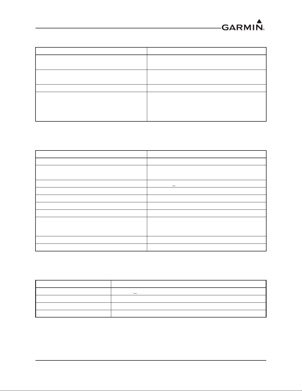
Table 1-5 Display Specifications
Characteristic Specification
Display size
Active area
Resolution 200 x 33 pixels
Viewing angle
Width: 3.46 inches (88 mm)
Height: 0.843 inches (21.4 mm)
Width: 2.95 inches (74.98 mm)
Height: 0.486 inches (12.36 mm)
Left: 45°
Right: 45°
From top: 30°
From bottom: 10°
1.8 Transponder Specifications
Table 1-6 Transponder Specifications
Characteristic Specification
Transmitter frequency 1090 MHz ± 1 MHz
Transmitter power
Receiver frequency
Receiver sensitivity
Mode A capability
Mode C altitude capability
Mode S capability (GTX 335 and GTX 345)
Mode S altitude capability (GTX 335 and
GTX 345)
External suppression input
External suppression output ≥ 18 Vdc with 300ohm load, 35Vdc max with no load
125 W min at antenna, with max 2db cable loss
250 W nominal at unit
1030 MHz + ?? MHz
-74 dBm nominal for 90% replies
4096 identification codes
100 foot increments from -1000 to 62,700 feet
Selective identification codes, aircraft type
25 foot increments from -1000 to 50,175 feet with
suitable serial data altitude. 100 foot increments from
-1000 to 62,700 feet
≥ 10 Vdc to suppress
1.9 UAT Receiver Specifications
Table 1-7 UAT Receiver Specifications
Characteristic Specification
Frequency 978 MHz +
Modulation Continuous phase FSK, h = 0.6, raised cosine shaping, a = 0.5
Data rate 1.04 Mbps
Sensitivity -96 dBm for 90% MSR
190-01499-02 GTX 3x5 TSO Installation Manual
Rev. 1 Page 1-8
20 ppm

1.10 1090 MHz Receiver Specifications
Table 1-8 1090 MHz Receiver Specifications
Characteristic Specification
Frequency 1090 MHz +
Modulation Binary pulse-position
Data rate 1 Mbps
Sensitivity -82 dBm for 90% MSR
1 MHz
1.11 GPS Specifications
Table 1-9 GNSS Receiver Specifications
Characteristic Specification
Number of channels 15 (12 GPS and 3 GPS/SBAS receiver [1]
Frequency 1575.42 MHz L1, C/A code
Sensitivity (acquisition, no interference)
Sensitivity (drop lock) -144 dBm
Dynamic range >20 dB
LAT/LON position accuracy
Velocity 1000 knots maximum (above 60,000 ft)
TTFF (Time To First Fix)
Reacquisition 10 seconds typical
Position update interval 0.2 sec (5 Hz)
1PPS (Pulse Per Second) ± 275 nsec of UTC second
Datum WGS-84
SATCOM compatibility
Antenna power supply 35 mA typical, 40 mA max at 4.7 Vdc
-134.5 dBm GPS
-135.5 dBm SBAS
<1.25 meter RMS horizontal, <2 meter vertical, with
SBAS
1:45 min. typical with current almanac, position, and
time
SATCOM compatibility is dependent on antenna
selection
[1] GBAS correction and integrity data provided by an external VHF receiver.
190-01499-02 GTX 3x5 TSO Installation Manual
Rev. 1 Page 1-9

1.12 GPS Antenna Requirements
Antenna performance is critical to GNSS receiver operation. Antennas listed in table 1-10 meet
specifications outlined in Antenna Minimum Performance Specification for Garmin’s GPS/WAAS Receiver
System. To achieve acceptable performance with the GTX 335 or GTX 345 with internal GNSS receiver,
antennas listed table 1-10 must be used.
Table 1-10 GNSS Receiver Antennas
Model/Description
GA 35, GPS/WAAS TNC
GA 36, GPS/WAAS TNC
GA 37, GPS/WAAS/
XM
A33W, WAAS
Antenna
GPS/VHF Antenna TNC/BNC Comant CI-2580-200 N/A
GPS/VHF Antenna TNC/BNC Comant CI-2728-200 N/A
GPS/XM/VHF
Antenna
GPS/XM/VHF
Antenna
GPS/WAAS Antenna TNC Comant CI-428-200 N/A
GPS/XM Antenna TNC/TNC Comant CI-428-410 N/A
Connector
Type
TNC
TNC
TNC/TNC/BNC Comant CI-2580-410 N/A
TNC/TNC/BNC Comant CI-2728-410 N/A
Manufacturer P/N
Garmin 013-00235-( ) 013-00235-( )
Aero Antenna
Garmin 013-00244-( ) 013-00244-( )
Aero Antenna
Garmin 013-00245-( ) 013-00245-( )
Aero Antenna
Garmin 013-00261-( ) 013-00261-( )
Aero Antenna
AT575-93G( )-TNCF-000-RG-27NM
AT575-126G( )-TNCF-000-RG-27NM
AT2300-126G( )-TNCF-000-RG-27NM
AT575-332G( )-TNCF-000-RG-27NM
Garmin
Order
Number
[1] Same mounting hole pattern as GA 56, except GA 35 has a physically larger footprint.
[2] The GPS antenna connector is a TNC and the VHF connector is BNC.
[3] The GPS antenna connector is a TNC connector, the XM connector is TNC, and the VHF
connector is BNC.
190-01499-02 GTX 3x5 TSO Installation Manual
Rev. 1 Page 1-10

1.13 Power Specifications
Table 1-11 Power Specifications
Unit Characteristic Specification
All units Input voltage 9 to 33 Vdc
14 Vdc 28 Vdc
GTX 325 Power input __ W typical, __ W max
Input current, typical
Input current, maximum
GTX 335 Power input 8 W typical, 15 W maximum
Input current, typical 0.57 A 0.29 A
Input current, maximum 0.86 A 0.43 A
GTX 335, GPS Power input 10 W typical, 17 W maximum
Input current, typical 0.72 A 0.36 A
Input current, maximum 1.22 A 0.61 A
GTX 345 Power input 10 W typical, 18 W maximum
Input current, typical 0.72 A 0.36 A
Input current, maximum 1.30 A 0.65 A
GTX 345, GPS Power input 12 W typical, 20 W maximum
Input current, typical 1.07 A 0.54 A
Input current, maximum 1.43 A 0.72 A
All units KEEP ALIVE input current
20 uA typical
40 uA maximum
65 uA typical
85 uA maximum
[1] Maximum input power and current is based upon maximum reply rates.
[2] Input power and current does not reflect the switched power output.
[3] KEEP ALIVE input only applies to the GTX 335 and GTX 345 with internal GNSS receiver.
190-01499-02 GTX 3x5 TSO Installation Manual
Rev. 1 Page 1-11

1.14 Certification
The GTX 3x5 meets compliance with the claimed TSO(s) when interfaced with the equipment defined in
this manual, and installed in accordance with the requirements and limitations as defined.
The Appliance Project Identifier (API) for the GTX 3x5 is GMN-01216. The API is used for project
identification with the FAA and EASA. In addition, the alpha character appended to the end of the API in
the ETSO certificate is added to supplement project identification by EASA. This alpha character does not
represent a version number. To identify appliance approvals, see applicable hardware and software
numbers.
It is the installer’s responsibility to ensure the ADS-B Out system is compliant with AC 20-165 and to
ensure compatibility between the GTX 335 or GTX 345 and the ADS-B Out position source equipment.
For compatible equipment shown to be eligible for 14 CFR 91.227 compliant installations in accordance
with AC 20-165, see 14 CFR 91.227 ADS-B Out Compatible Equipment.
Table 1-12 TSO/ETSO Compliance
GTX
325
GTX
335
X TSO-C74d Class A
XXX
[1] With internal GPS.
[2] With optional pressure sensor module.
GTX
345
TSO-C88b
ETSO-C88a
XX
XX
X
TSO-C112e
ETSO-C112d
TSO-C145d
ETSO-C145c1
TSO-C154c
X
ETSO-C154c
TSO-C157a
X
ETSO-C157a
TSO-C166b
ETSO-C166b
TSO-C166b
X
ETSO-C166b
TSO-C195a
X
ETSO-C195a
TSO/ETSO
Class
Level
--
Class 1
Level 2es
Class B2
Class A1S
Class 1
Class B1S
Class A1S
Class C1,
C2, C3, C4
and
Software and CLD P/N Description
Software:
006-B____-00 through -0( )
006-B____-00 through -0( )
006-B____-00 through -0( )
CLDs:
006-C____-00 through -0( )
006-C____-00 through -0( )
Main
ADS-B In
GPS
Main
ADS-B In
190-01499-02 GTX 3x5 TSO Installation Manual
Rev. 1 Page 1-12

Table 1-13 TSO and ETSO Descriptions
TSO/ETSO Description
TSO-C74d Air Traffic Control Radar Beacon System (ATCRBS) Airborne Equipment
TSO-C88b
ETSO-C88a
TSO-C112e
ETSO-C112d
TSO-C145d
ETSO-C145c
TSO-C154c
ETSO-C154c
TSO-C157a
ETSO-C157a
TSO-C166b
ETSO-C166b
TSO-C195a
ETSO-C195a
Automatic Pressure Altitude Reporting Code-Generating Equipment
Air Traffic Control Radar Beacon System / Mode Select (ATCRBS/Mode S)
Airborne Equipment
Airborne Navigation Sensors Using the Global Positioning System
Augmented by the Satellite Based Augmentation System
Universal Access Transceiver (UAT) Automatic Dependent Surveillance –
Broadcast (ADS-B) Equipment Operating on Frequency of 978 MHz
Aircraft Flight Information Services – Broadcast (FIS-B) Data Link System
and Equipment
Extended Squitter Automatic Dependent Surveillance – Broadcast (ADS-B)
and Traffic Information Service – Broadcast (TIS-B) Equipment Operating on
the Radio Frequency of 1090 Megahertz (MHz)
Avionics Supporting Automatic Dependent Surveillance – Broadcast
(ADS-B) Aircraft Surveillance Applications (ASA)
Table 1-14 TSO/ETSO Deviations
TSO/ETSO Deviation
1. Garmin requests a deviation from the mentioned TSOs to use RTCA DO-160G instead
TSO-C74d
TSO-C88b
TSO-C112e
of earlier versions of RTCA/DO-160 as the standard for Environmental Conditions and
Test Procedures for Airborne Equipment. ELOS is provided by use of later revision
requirement document. Refer to AC 21-16G for supporting guidance.
1. Garmin requests a deviation from the mentioned TSOs for marking the TSO number,
Type/Class and Date of Manufacture, Deviation and Software Part Number on the
exterior of the unit. Instead, Garmin requests to include product name, part number,
serial number, and this statement on the unit’s nameplate label “TSO-C112e See IM for
Add’l Appliance Apprvls.” The installation manual will contain all equipment approvals,
classes/types/ranges and TSO deviations as required by the TSOs, and the software
part numbers for the unit will be available through electronic query within the unit. ELOS
is provided because the installation manual will list all applicable information and the
article will permanently and legibly list the Primary TSO and state “See IM for Add’l
Appliance Apprvls.” All software part numbers can be verified through electronic query.
See Order 8150.1C Section 7-4e-4 and 8110.49 for further supporting statement of
policy.
1. Garmin requests a deviation from the mentioned TSOs for marking the TSO number,
Type/Class and Date of Manufacture, Deviation and Software Part Number on the
exterior of the unit. Instead, Garmin requests to include product name, part number,
serial number, and this statement on the unit’s nameplate label “TSO-C112e See IM for
Add’l Appliance Apprvls.” The installation manual will contain all equipment approvals,
classes/types/ranges and TSO deviations as required by the TSOs, and the software
part numbers for the unit will be available through electronic query within the unit. ELOS
is provided because the installation manual will list all applicable information and the
article will permanently and legibly list the Primary TSO and state “See IM for Add’l
Appliance Apprvls.” All Software part numbers can be verified through electronic query.
See Order 8150.1C Section 7-4e-4 and 8110.49 for further supporting statement of
policy.
190-01499-02 GTX 3x5 TSO Installation Manual
Rev. 1 Page 1-13
 Loading...