

Page 1
GTX 33
Transponder
Installation Manual
190-00906-00 September, 2012 Revision H
Page 2
© Copyright 2012
Garmin Ltd. or its subsidiaries
All Rights Reserved
Except as expressly provided herein, no part of this manual may be reproduced, copied, transmitted,
disseminated, downloaded or stored in any storage medium, for any purpose without the express prior
written consent of Garmin. Garmin hereby grants permission to download a single copy of this manual and
of any revision to this manual onto a hard drive or other electronic storage medium to be viewed and to
print one copy of this manual or of any revision hereto, provided that such electronic or printed copy of this
manual or revision must contain the complete text of this copyright notice and provided further that any
unauthorized commercial distribution of this manual or any revision hereto is strictly prohibited.
Garmin International, Inc.
1200 E. 151st Street
Olathe, KS 66062 USA
Telephone: 913.397.8200
Aviation Panel-Mount Technical Support Line (Toll Free) 1.888.606.5482
www.garmin.com
Garmin (Europe) Ltd.
Liberty House, Bulls Copse Road
Hounsdown Business Park
Southampton, SO40 9RB U.K.
+44/ (0) 870.8501241
Garmin AT, Inc.
2345 Turner Rd., SE
Salem, OR 97302 USA
Telephone: 503.581.8101
RECORD OF REVISIONS
Revision Revision Date Description
A 9/22/08 Production Release
B 2/26/09 Clarified model name
C 9/3/10
D 10/27/10
E 3/21/12 Added ADS-B info
F 6/13/12 Added TNC connectors
G 09/11/12 Updated per SW v7.00
H 09/24/12 Updated per SW v7.01
Updated outline/installation drawings and interconnects, added
ETSO information
Added GTX 33H, GTX 33DH, and non-extended squitter units info,
simplified doc title
GTX 33 Installation Manual 190-00906-00
Page A Rev. H
Page 3
CURRENT REVISION DESCRIPTION
Revision
H
Page
Number(s)
1-3 1.3.1 Updated SW version
1-4 1.3.1.2 Updated SW version
1-10
Section
Number
1.9.1 Updated SW version
DOCUMENT PAGINATION
Section Page Range
Table of Contents i – x
Section 1 1-1 – 1-12
Section 2 2-1 – 2-10
Section 3 3-1 – 3-8
Section 4 4-1 – 4-10
Appendix A A-1 – A-2
Appendix B B-1 – B-18
Appendix C C-1 – C-6
Appendix D D-1 – D-7
Description of Change
190-00906-00 GTX 33 Installation Manual
Rev. H Page i
Page 4
INFORMATION SUBJECT TO EXPORT CONTROL LAWS
WARNING
NOTE
This document may contain information which is subject to the Export Administration
Regulations (“EAR”) issued by the United States Department of Commerce (15 CFR,
Chapter VII Subchapter C) and which may not be exported, released or disclosed to
foreign nationals inside or outside the United States without first obtaining an export
license. The preceding statement is required to be included on any and all reproductions
in whole or in part of this manual.
DEFINITIONS OF WARNINGS, CAUTIONS, AND NOTES
WARNING
Warni n gs are used to bring to the installer’s immediate attention that not only
damage to the equipment but personal injury may occur if the instruction is
disregarded.
CAUTION
Cautions are used to alert the individual that damage to equipment may
result if the procedural step is not followed to the letter.
NOTE
Notes are used to expand and explain the preceding step and provide further
understanding of the reason for the particular operation.
This product, its packaging, and its components contain chemicals known to the State of
California to cause cancer, birth defects, or reproductive harm. This Notice is being
provided in accordance with California's Proposition 65. If you have any questions or
would like additional information, please refer to our web site at www.garmin.com/prop65
Throughout this document references made to GTX 33 shall equally apply to the GTX 33,
GTX 33D, GTX 33H, and GTX 33DH, with or without Extended Squitter; except where
specifically noted.
.
GTX 33 Installation Manual 190-00906-00
Page ii Rev. H
Page 5
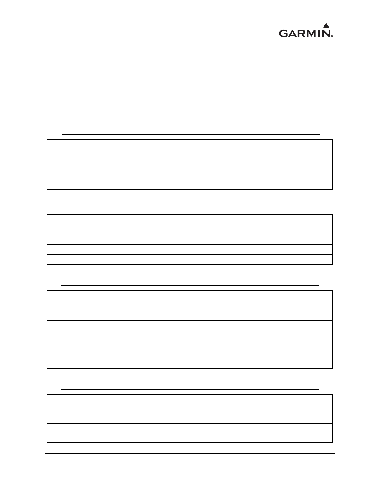
GTX 33 HARDWARE MOD LEVEL HISTORY
The following table identifies hardware modification (Mod) Levels for the GTX 33. Mod Levels are listed
with the associated service bulletin number, service bulletin date, and the purpose of the modification. The
table is current at the time of publication of this manual (see date on front cover) and is subject to change
without notice. Authorized Garmin Sales and Service Centers are encouraged to access the
most up-to-date bulletin and advisory information on the Garmin web site at
www.garmin.com using their Garmin-provided user name and password.
GTX 33 P/N 011-00779-00, 011-00779-20 HARDWARE MOD LEVEL HISTORY
MOD
LEVEL
1 0710 05/18/07 Improve decay time of the suppression circuit
SERVICE
BULLETIN
NUMBER
SERVICE
BULLETIN
DATE
PURPOSE OF MODIFICATION
GTX 33 P/N 011-00779-10, 011-00779-30 HARDWARE MOD LEVEL HISTORY
MOD
LEVEL
1 0624 04/28/07 Improve rejection of high-power in-band signals
2 0710 05/18/07 Improve decay time of the suppression circuit
SERVICE
BULLETIN
NUMBER
SERVICE
BULLETIN
DATE
PURPOSE OF MODIFICATION
GTX 33 P/N 011-00779-01, 011-00779-21 HARDWARE MOD LEVEL HISTORY
MOD
LEVEL
1 0311 02/06/04
2 0624 04/25/07 Improve rejection of high-power in-band signals
3 0710 05/18/07 Improve decay time of the suppression circuit
SERVICE
BULLETIN
NUMBER
SERVICE
BULLETIN
DATE
PURPOSE OF MODIFICATION
GTX 33D Only. Switch/Diplexer Assembly
reworked to prevent +200 Volt supply line from
shorting to the chassis.
GTX 33 P/N 011-00779-50, 011-00779-70 HARDWARE MOD LEVEL HISTORY
MOD
LEVEL
None at
this time
190-00906-00 GTX 33 Installation Manual
Rev. H Page iii
SERVICE
BULLETIN
NUMBER
SERVICE
BULLETIN
DATE
PURPOSE OF MODIFICATION
Page 6

Limited Warranty
All Garmin avionics products are warranted to be free from defects in materials or workmanship for: one
years from the date of purchase for new Remote-Mount and Panel-Mount products; one year from the date
of purchase for new portable products and any purchased newly-overhauled products; six months for
newly-overhauled products exchanged through a Garmin Authorized Service Center; and 90 days for
factory repaired or newly-overhauled products exchanged at Garmin in lieu of repair. Within the
applicable period, Garmin will, at its sole option, repair or replace any components that fail in normal use.
Such repairs or replacement will be made at no charge to the customer for parts or labor, provided that the
customer shall be responsible for any transportation cost. This warranty does not apply to: (i) cosmetic
damage, such as scratches, nicks and dents; (ii) consumable parts, such as batteries, unless product damage
has occurred due to a defect in materials or workmanship; (iii) damage caused by accident, abuse, misuse,
water, flood, fire, or other acts of nature or external causes; (iv) damage caused by service performed by
anyone who is not an authorized service provider of Garmin; or (v) damage to a product that has been
modified or altered without the written permission of Garmin. In addition, Garmin reserves the right to
refuse warranty claims against products or services that are obtained and/or used in contravention of the
laws of any country.
THE WARRANTIES AND REMEDIES CONTAINED HEREIN ARE EXCLUSIVE AND IN LIEU OF
ALL OTHER WARRANTIES, WHETHER EXPRESS, IMPLIED OR STATUTORY, INCLUDING
ANY LIABILITY ARISING UNDER ANY WARRANTY OF MERCHANTABILITY OR FITNESS
FOR A PARTICULAR PURPOSE, STATUTORY OR OTHERWISE. THIS WARRANTY GIVES YOU
SPECIFIC LEGAL RIGHTS, WHICH MAY VARY FROM STATE TO STATE.
IN NO EVENT SHALL GARMIN BE LIABLE FOR ANY INCIDENTAL, SPECIAL, INDIRECT OR
CONSEQUENTIAL DAMAGES, WHETHER RESULTING FROM THE USE, MISUSE OR
INABILITY TO USE THE PRODUCT OR FROM DEFECTS IN THE PRODUCT. SOME STATES DO
NOT ALLOW THE EXCLUSION OF INCIDENTAL OR CONSEQUENTIAL DAMAGES, SO THE
ABOVE LIMITATIONS MAY NOT APPLY TO YOU.
Garmin retains the exclusive right to repair or replace (with a new or newly-overhauled replacement
product) the product or software or offer a full refund of the purchase price at its sole discretion. SUCH
REMEDY SHALL BE YOUR SOLE AND EXCLUSIVE REMEDY FOR ANY BREACH OF
WARRANTY.
Online Auction Purchases: Products purchased through online auctions are not eligible for warranty
coverage. Online auction confirmations are not accepted for warranty verification. To obtain warranty
service, an original or copy of the sales receipt from the original retailer is required. Garmin will not
replace missing components from any package purchased through an online auction.
International Purchases: A separate warranty may be provided by international distributors for devices
purchased outside the United States depending on the country. If applicable, this warranty is provided by
the local in-country distributor and this distributor provides local service for your device. Distributor
warranties are only valid in the area of intended distribution. Devices purchased in the United States or
Canada must be returned to the Garmin service center in the United Kingdom, the United States, Canada,
or Taiwan for service.
Garmin International, Inc. Garmin (Europe) Ltd.
1200 East 151st Street Liberty House, Bulls Copse Road
Olathe, Kansas 66062, U.S.A. Hounsdown Business Park
Phone:913/397.8200 Romsey, SO40 9RB, U.K.
FAX:913/397.0836 Phone:44/ (0) 870.8501241
FAX:44/ (0) 870.850125
GTX 33 Installation Manual 190-00906-00
Page iv Rev. H
Page 7

TABLE OF CONTENTS
PARAGRAPH PAGE
Section 1 GENERAL DESCRIPTION .............................................................1-1
1.1 Introduction...................................................................................................................... 1-1
1.2 Equipment Description .................................................................................................... 1-1
1.3 ADS-B Capabilities ......................................................................................................... 1-2
1.4 TIS System Capabilities................................................................................................... 1-4
1.5 Mutual Suppression Pulses .............................................................................................. 1-4
1.6 Interface Summary...........................................................................................................1-5
1.7 Technical Specifications .................................................................................................. 1-6
1.8 Operating Instructions......................................................................................................1-8
1.9 Aircraft Station Licensing Requirements ........................................................................ 1-8
1.10 Certification ................................................................................................................... 1-9
1.11 Operating Instructions.................................................................................................. 1-11
1.12 Reference Documents .................................................................................................. 1-12
Section 2 INSTALLATION OVERVIEW........................................................2-1
2.1 Introduction...................................................................................................................... 2-1
2.2 Installation Materials ....................................................................................................... 2-1
2.3 Installation Considerations .............................................................................................. 2-3
2.4 Cabling and Wiring..........................................................................................................2-5
2.5 Installation Approval Considerations for Pressurized Aircraft........................................ 2-6
2.6 Cooling Air ...................................................................................................................... 2-6
2.7 GTX 33 Mounting Requirements .................................................................................... 2-7
Section 3 INSTALLATION PROCEDURE.....................................................3-1
3.1 Unpacking Unit................................................................................................................ 3-1
3.2 Wiring Harness Installation ............................................................................................. 3-1
3.3 Backshell Assembly......................................................................................................... 3-3
3.4 Weight and Balance ......................................................................................................... 3-5
3.5 Electrical Load Analysis.................................................................................................. 3-5
3.6 Final Installation .............................................................................................................. 3-5
3.7 Post Installation Configuration and Checkout ................................................................. 3-6
3.8 Continued Airworthiness ................................................................................................. 3-8
Section 4 SYSTEM INTERCONNECTS..........................................................4-1
4.1 Pin List............................................................................................................................. 4-1
4.2 Power Functions .............................................................................................................. 4-3
4.3 Temperature Inputs ..........................................................................................................4-4
4.4 Altitude Functions............................................................................................................ 4-4
4.5 Discrete Functions ........................................................................................................... 4-6
4.6 Serial Data Electrical Characteristics .............................................................................. 4-7
190-00906-00 GTX 33 Installation Manual
Rev. H Page v
Page 8

PARAGRAPH PAGE
4.7 RS-232 Input/Output, Software Update Connections...................................................... 4-9
Appendix A CONSTRUCTION AND VALIDATION OF
STRUCTURES.............................................................................A-1
A.1 Static Test Loading ........................................................................................................ A-1
A.2 Determining Static Load Capability .............................................................................. A-1
Appendix B VERSION 1 ADS-B FIELD APPROVAL COMPLIANCE
MATRIX .......................................................................................B-1
Appendix C OUTLINE AND INSTALLATION DRAWINGS.....................C-1
Appendix D INTERCONNECT DRAWINGS................................................D-1
GTX 33 Installation Manual 190-00906-00
Page vi Rev. H
Page 9

LIST OF FIGURES
FIGURE PAGE
Section 1 GENERAL DESCRIPTION .............................................................1-1
Section 2 INSTALLATION OVERVIEW........................................................2-1
Figure 2-1. Antenna Installation Considerations .................................................................. 2-4
Figure 2-2. GTX 33 Modular Rack (115-00438-00) ............................................................ 2-8
Figure 2-3. GTX 33 Stand-Alone Rack (115-00629-00)...................................................... 2-8
Figure 2-4. GTX 33H Stand-Alone Rack (011-02422-00)................................................... 2-9
Figure 2-5. GTX 33 Stand-Alone Rack, Suggested Mounting Locations .......................... 2-10
Section 3 INSTALLATION PROCEDURE.....................................................3-1
Section 4 SYSTEM INTERCONNECTS..........................................................4-1
Figure 4-1. View of J3301 connector from back of unit ...................................................... 4-1
Figure 4-2. GTX 33 Software Update Connections ............................................................. 4-9
Appendix A CONSTRUCTION AND VALIDATION OF
STRUCTURES.............................................................................A-1
Figure A-1. Upward Static Load Test.................................................................................. A-2
Figure A-2. Forward Static Load Test ................................................................................. A-2
Appendix B VERSION 1 ADS-B FIELD APPROVAL COMPLIANCE
MATRIX.......................................................................................B-1
Appendix C OUTLINE AND INSTALLATION DRAWINGS ....................C-1
Figure C-1 GTX 33 in Modular Rack, Outline Drawing......................................................C-1
Figure C-2 GTX 33 G1000 Connector/Rack Assembly Drawing ........................................C-2
Figure C-3 GTX 33 Remote Stand-Alone Rack/Connector Assembly (Sheet 1 of 2) .........C-3
Figure C-3 GTX 33 Remote Stand-Alone Rack/Connector Assembly (Sheet 2 of 2) .........C-4
Figure C-4 GTX 33H Remote Stand-Alone Rack/Connector Assembly (Sheet 1 of 2) ......C-5
Figure C-4 GTX 33H Remote Stand-Alone Rack/Connector Assembly (Sheet 2 of 2) ......C-6
Appendix D INTERCONNECT DRAWINGS ...............................................D-1
Figure D-1 GTX 33 Typical Garmin Integrated Flight Deck Interconnect Wiring
Diagram ................................................................................................................................ D-1
Figure D-2 GTX 33 to GNS 480 (CNX 80) Simplified Interconnect Wiring Diagram ...... D-2
Figure D-3 GTX 33 to MFD, Simplified Interconnect Wiring Diagram............................. D-3
Figure D-4 Dual GTX 33 to GNS 480 (CNX80) Interconnect Wiring Diagram,
Single Altitude Encoder (Sheet 1 of 2)................................................................................. D-4
190-00906-00 GTX 33 Installation Manual
Rev. H Page vii
Page 10

FIGURE PAGE
Figure D-4 Dual GTX 33 to GNS 480 (CNX80) Interconnect Wiring Diagram,
Single Altitude Encoder (Sheet 2 of 2)................................................................................. D-5
Figure D-5 Dual GTX 33 to GTN 6XX/7XX Interconnect Wiring Diagram, Encoding
Altitude Connections (Sheet 1 of 2) ..................................................................................... D-6
Figure D-5 Dual GTX 33 to GTN 6XX/7XX Interconnect Wiring Diagram, Encoding
Altitude Connections (Sheet 2 of 2) ..................................................................................... D-7
GTX 33 Installation Manual 190-00906-00
Page viii Rev. H
Page 11

LIST OF TABLES
TABLE PAGE
Section 1 GENERAL DESCRIPTION .............................................................1-1
Table 1-1 ADS-B Versions................................................................................................... 1-3
Table 1-2. GTX 33 Physical Characteristics ........................................................................ 1-6
Table 1-3. GTX 33 General Specifications .......................................................................... 1-7
Table 1-4. GTX 33 Power Requirements ............................................................................. 1-7
Table 1-5 TSO/ETSO/RTCA/ICAO Compliance ................................................................ 1-9
Table 1-6 TSO/ETSO Deviations ....................................................................................... 1-11
Table 1-7. GTX 33 Reference Documents ......................................................................... 1-12
Section 2 INSTALLATION OVERVIEW........................................................2-1
Table 2-1. GTX 33 Part Numbers......................................................................................... 2-1
Table 2-2. GTX 33 Accessories............................................................................................ 2-2
Table 2-3. GTX 33 Cabling and Wiring ............................................................................... 2-5
Section 3 INSTALLATION PROCEDURE.....................................................3-1
Table 3-1 Pin Contact Part Numbers (High Density) ........................................................... 3-1
Table 3-3. Recommended Crimp Tools................................................................................ 3-2
Table 3-2 Recommended Crimp Tools (High Density)........................................................ 3-2
Table 3-4. Unit Power Loads................................................................................................ 3-5
Section 4 SYSTEM INTERCONNECTS..........................................................4-1
Table 4-1. P3301 Pin List ..................................................................................................... 4-1
Table 4-2. Aircraft Power ..................................................................................................... 4-3
Table 4-3. Temperature Inputs.............................................................................................. 4-4
Table 4-4. Altimeter Inputs................................................................................................... 4-5
Table 4-5. Discrete Outputs .................................................................................................. 4-6
Table 4-6. Discrete Inputs.....................................................................................................4-6
Table 4-7. RS-232 Input/Output ........................................................................................... 4-7
Table 4-8. ARINC 429 Channels.......................................................................................... 4-8
Table 4-9. ARINC Labels..................................................................................................... 4-8
Appendix A CONSTRUCTION AND VALIDATION OF
STRUCTURES ............................................................................A-1
Table A-1. Static Test Load............................................................................................... A-1
Appendix B VERSION 1 ADS-B FIELD APPROVAL COMPLIANCE
MATRIX ......................................................................................B-1
Table B-1. Version 1 ADS-B Field Approval Compliance Matrix ....................................B-2
190-00906-00 GTX 33 Installation Manual
Rev. H Page ix
Page 12

TABLE PAGE
Appendix C OUTLINE AND INSTALLATION DRAWINGS ....................C-1
Appendix D INTERCONNECT DRAWINGS ...............................................D-1
GTX 33 Installation Manual 190-00906-00
Page x Rev. H
Page 13

1 GENERAL DESCRIPTION
NOTE
1.1 Introduction
This manual is intended to provide mechanical and electrical information for use in the planning and
design of an installation of the Garmin GTX 33 Mode S Transponder into an aircraft. These versions
include all GTX 33, GTX 33D, GTX 33H, and GTX 33DH units with or without Extended Squitter
Enabled; as part of a Garmin Integrated Flight Deck. This manual is not a substitute for an approved
airframe-specific maintenance manual, installation design drawing, or complete installation data package.
Attempting to install equipment by reference to this manual alone and without first planning or designing
an installation specific to your aircraft may compromise your safety and is not recommended. The content
of this manual assumes use by competent and qualified avionics engineering personnel and/or avionics
installation specialists using standard aviation maintenance practices in accordance with Title 14 of the
Code of Federal Regulations and other relevant accepted practices. This manual is not intended for use by
individuals who do not possess the competencies and abilities set forth above.
Garmin recommends installation of the GTX 33 by a Garmin-authorized installer. To the
extent allowable by law, Garmin will not be liable for damages resulting from improper or
negligent installation of the GTX 33. For questions, please contact Garmin Aviation
Product Support at 1-888-606-5482.
The GTX 33 can also be incorporated as a remote mounted unit in installations with other compatible
control/display units such as the Garmin GNS 480 (CNX80), GTN 6XX/7XX, and GMX 200 (MX20)
Multifunction Display (MFD).
1.2 Equipment Description
The Garmin GTX 33 rack mounted Mode S Transponder is a radio transmitter and receiver that operates
on radar frequencies, receiving ground radar and TCAS interrogations at 1030 MHz and transmitting a
coded response of pulses on a frequency of 1090 MHz. The GTX 33 is equipped with IDENT capability
that activates the Special Position Identification (SPI) pulse for 18 seconds.
The GTX 33 replies to Mode A, Mode C and Mode S interrogation. Mode A replies consist of framing
pulses and any one of 4,096 codes, which differ in the position and number of pulses transmitted. Mode C
replies include framing pulses and encoded altitude.
The GTX 33 with Extended Squitter Enabled provides Automatic Dependent Surveillance-Broadcast
(ADS-B) technology that improves situational awareness and flight safety. With ADS-B capabilities,
position, velocity, and heading information are automatically transmitted to other aircraft and ground
stations. The current air traffic control system depends on the transmission of interrogations for pertinent
aircraft information at a slower update rate. ADS-B provides immediate surveillance of air-to-air traffic
and aircraft in remote or inhospitable areas not currently covered by radar.
Ground stations can interrogate Mode S Transponders individually using a 24-bit ICAO Mode S address,
which is unique to the particular aircraft. In addition, ground stations may interrogate a GTX 33 for its
Transponder data capability and the aircraft's Flight ID, which is the registration number or other call sign.
The GTX 33 makes the maximum airspeed capability (set during configuration setup) available to TCAS
systems on-board nearby aircraft to aid in the determination of TCAS advisories.
The unit features an altitude monitor and TIS traffic advisories. A voice or tone audio output announces
altitude and traffic alerts. The GDU Primary Flight Display screen displays the code, reply symbol and
mode of operation, depending on equipment connections and configuration selection. The GNS 480
190-00906-00 GTX 33 Installation Manual
Rev. H Page 1-1
Page 14

(CNX80), GTN 6XX/7XX, and GMX 200 (MX20) MFD provide similar information with the addition of
NOTE
pressure altitude.
The GTX 33 features multiple transmit/receive ARINC 429 and RS-232 data ports. The unit concentrates
data from three ARINC 429 inputs, gray code, RS-232 input data and discrete inputs to the high-speed
RS-232 data ports for display on the flight displays. Although multiple output capability is available, the
unit is designed to feed all outgoing data via RS-232 data ports. Two RS-232 data ports send and receive
data to/from the GIA 63(W) Integrated Avionics Units (IAU), GNS 480 (CNX80), GTN 6XX/7XX, or
GMX 200 (MX20) Multifunction Display.
Provision is made for unit software upgrade by means of RS-232 data through rear connector pins. In
installations where the transponder interfaces with a GNS 480 (CNX80) or GTN 6XX/7XX the installation
of an optional connector is highly recommended. If the optional connector is placed in the aircraft,
transponder removal and reinstallation for software upgrade is not required. The software can be changed
while the unit is still mounted inside the aircraft.
The GTX 33 meets Mode S Enhanced Surveillance (EHS) requirements. Mode S Enhanced Surveillance is
used predominantly in European airspace. It provides information consisting of additional aircraft
parameters (see JAA NPA 20-12a) to ground radar systems. Compliance with Enhanced Surveillance may
require additional interface between aircraft systems and the GTX 33.
The GTX 33 and GTX 33D differ from the GTX 33H and GTX 33DH in the qualified DO-160 vibration
categories. See the GTX 33 Environmental Qualification Form (005-00131-03) for details.
1.3 ADS-B Capabilities
The Extended Squitter Enabled GTX 33 provides the capabilities of Automatic Dependent SurveillanceBroadcast (ADS-B) technology, which improves situational awareness and flight safety. With ADS-B
capabilities, position, velocity, and heading information are automatically transmitted to other aircraft and
ground stations. The current air traffic control system depends on a transponder request for pertinent
aircraft information. ADS-B provides automatic transmission of aircraft information without a request.
RS-232 ADS-B Out from a Garmin 4XX/5XX WAAS, GTN 6XX/7XX with GPS software
version 3.20 or later, or a GPS WAAS source that supports ARINC 743A output is required
to support ADS-B transmissions.
GTX 33 Installation Manual 190-00906-00
Page 1-2 Rev. H
Page 15
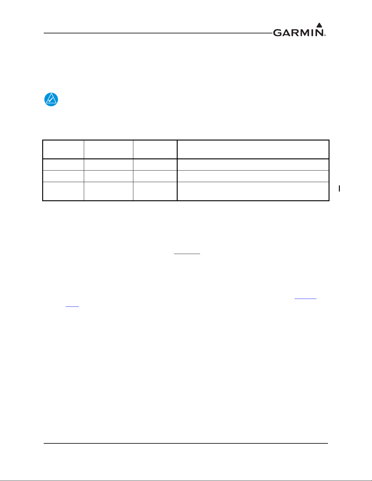
1.3.1 ADS-B Versions
NOTE
There are three distinct ADS-B versions recognized by regulatory authorities. As show in the table below,
the Garmin GTX 33 w/ES currently supports ADS-B Out 1090MHz Extended Squitter capability meeting
‘Version 1’ ADS-B or ‘Version 2' ADS-B system requirements depending on software version (see Table
1-1).
GTX 33 w/ES transponders with software version 6.20 or earlier are not compliant with
ADS-B version required by the 14 CFR 91.225(a) equipage mandate.
Table 1-1 ADS-B Versions
ADS-B
Version
Version 0 No None Equipment designed to TSO-166 / RTCA DO-260
Version 1 Yes 6.00 - 6.20 Equipment designed to TSO-166a / RTCA DO-260A
Version 2* Yes
*Version required by 2020 ADS-B Out mandate defined in 14 CFR 91.225
GTX 33 w/ES
Compliant
Supported
SW Version
7.01
and later
Regulatory Standard/Minimum Performance
Specification
Equipment designed to TSO-166b / RTCA DO-260B
1.3.1.1 Installation Approval of Version 1 ADS-B Systems
GTX 33 w/ES transponders running software versions v6.00 through v6.20 support Version 1 ADS-B Out
functionality. According to AIR-130 Policy Memo ‘Approval for ADS-B Out Systems’, dated August 30,
2010, the FAA has suspended field approvals of Version 2
ADS-B Out equipment. At the time of this
publication, there is currently no FAA policy addressing field approvals of Version 0 or Version 1 systems.
GTX 33 w/ES transponders with Version 1 ADS-B remain eligible for field approval.
There are three options for installers wanting to install GTX 33 w/ES transponders with software versions
6.00 through 6.20:
1. Installers may elect to disable the ADS-B Extended Squitter function, as described in Section
3.7.1.
2. Installers may utilize a Supplemental Type Certificate (STC) for the GTX 33 with the Version 1
ADS-B Extended Squitter activated.
3. Installers may obtain a field approval with the Version 1 ADS-B Extended Squitter activated.
EASA AMC 20-24 compliance matrix provided in Appendix B may be used to assist installers in
showing compliance to the AMC requirements. This data together with Form 337 may be used for
approval by the appropriate FSDO inspector.
190-00906-00 GTX 33 Installation Manual
Rev. H Page 1-3
Page 16

1.3.1.2 Installation Approval of Version 2 ADS-B Systems
NOTE
GTX 33 w/ES transponders running software versions v7.01 and later support Version 2 ADS-B Out
functionality. According to AIR-130 Policy Memo ‘Approval for ADS-B Out Systems’, dated August 30,
2010, a Supplemental Type Certificate (STC) is required for the approval of Version 2 ADS-B Out
equipment.
There are two options for installers wanting to install GTX 33 w/ES transponders running software
versions v7.01 and later:
1. Installers may elect to disable the ADS-B Extended Squitter function, as described in Section
3.7.1.
2. Installers must utilize a Supplemental Type Certificate (STC) for the GTX 33 with the Version 2
ADS-B Extended Squitter activated.
It is the installer’s responsibility to ensure the ADS-B Out system is compliant with
AC 20-165 and to ensure compatibility between the GTX 33 and the ADS-B Out position
source equipment. See Garmin ADS-B Out Compatible Equipment (190-01533-00) for
compatible equipment shown to be eligible for 14 CFR 91.227-compliant installations in
accordance with AC 20-165
1.4 TIS System Capabilities
Traffic Information Service (TIS) provides a graphic display of traffic advisory information in the cockpit
for non-TCAS equipped aircraft.
TIS is a ground-based service providing relative location of all transponder equipped aircraft within a
specified service volume. The TIS ground sensor uses real time track reports to generate traffic
notification.
Traffic display is available to aircraft equipped with a Mode S data link such as the Garmin GTX 33
transponder. Traffic can then be displayed on a Garmin GDU Primary Flight Display, GMX 200 (MX20)
Multifunction Display, GNS 480 (CNX80), GTN 6XX/7XX or other compatible display unit.
Surveillance data includes all transponder equipped aircraft within the coverage volume. Aircraft without
an operating transponder are invisible to TIS. TIS displays traffic within seven nautical miles from 3000
feet below to 3500 feet above the requesting aircraft.
1.5 Mutual Suppression Pulses
Other equipment on board the aircraft may transmit in the same frequency band as the transponder, such as
DME or another transponder. Mutual suppression is a synchronous pulse that is sent to the other equipment
to suppress transmission of a competing transmitter for the duration of the pulse train transmission. The
transponder transmission is suppressed by an external source and other equipment on board is suppressed
by the GTX 33 transponder. This feature is designed to limit mutual interference.
GTX 33 Installation Manual 190-00906-00
Page 1-4 Rev. H
Page 17

1.6 Interface Summary
The GTX 33 provides the following interface connections via the rear connector. See Section 4 and
Appendix D
• Ten (10) encoding altimeter inputs
• External IDENT input
• External STBY input (useful for dual transponder installations)
• External suppression pulse input
• Switched power output of up to 1.5 amps (for digital altitude encoder power)
• Aircraft power input (14/28 Vdc)
• Remote power turn on
• Serial airdata or GPS groundspeed input
• Serial altitude input (Reduces wire count vs. parallel wire gray code altimeter interface.)
• Software update input
• Supports Comm-A and Comm-B protocol
• Temperature, Altitude Hold and Density Altitude
• Digitally recorded voice and discrete warning annunciator activated by Altitude Hold when limits
• Diversity: GTX 33D is available with the diversity feature
• ARINC 429 input
The GTX 33 P/N 010-00267-() and GTX 33D 010-00294-() support the following list of Comm-B
Definition Subfield (BDS) registers:
for connection details.
are exceeded
• BDS (0,0) Air Initiated Comm-B (AICB).
• BDS (1,0) Data Link Capability Report.
• BDS (1,7) Common Usage Ground Initiated Comm-B (GICB) Capability Report.
• BDS (1,8) Mode S Specific Services GICB Capability Report.
• BDS (1,9) Mode S Specific Services GICB Capability Report.
• BDS (1,D) Mode S Specific Services Protocols (MSP) Capability Report.
• BDS (2,0) Aircraft Identification.
• BDS (4,0) Selected Vertical Intention
• BDS (5,0) Track and Turn Report
• BDS (6,0) Heading and Speed Report
• BDS (0,6) Extended Squitter surface Position
• BDS (0,5) Extended Squitter Airborne Position
• BDS (0,8) Extended Squitter Aircraft Identification and Category
• BDS (0,9) Extended Squitter Airborne Velocity – Subtypes 1 and 3
• BDS (0,A) Extended Squitter Event Driven Data
• BDS (6,1) Emergency/Priority Status
• BDS (6,5) Aircraft operational Status
190-00906-00 GTX 33 Installation Manual
Rev. H Page 1-5
Page 18

1.7 Technical Specifications
It is the responsibility of the installing agency to obtain the latest revision of the GTX 33 Environmental
Qualification Form. This form is available directly from Garmin under the following part number:
GTX 330/GTX 33/GTX 328/GTX 23 Environmental Qualification Form,
Garmin part number 005-00131-03
To obtain a copy of this form, see the dealer/OEM portion of the Garmin web site (www.garmin.com
1.7.1 Physical Characteristics
Table 1-2. GTX 33 Physical Characteristics
Characteristic Specification
Modular Rack Width 1.72 Inches (44 mm)
Modular Rack Height 6.30 Inches (160 mm)
Modular Rack Weight 0.4 lbs. (0.18 kg)
Stand-Alone Rack Width 1.78 Inches (45 mm)
Stand-Alone Rack Height 6.92 Inches (176 mm)
Stand-Alone Rack Weight 0.9 lbs. (0.41 kg)
Stand-Alone H Rack Width 1.77 Inches (45 mm)
Stand-Alone H Rack Height 6.98 Inches (177 mm)
Stand-Alone H Rack Weight 0.7 lbs. (0.29 kg)
Depth Including Connectors (measured from front
face of unit to rear of connector backshells)
Depth Including Connectors and Shield Blocks
(measured from front face of unit to rear of shield
blocks)
11.05 Inches (281 mm)
(Modular and Stand-Alone)
11.44 inches (291 mm)
(Modular and Stand-Alone)
).
Connecter Weight (including backshell) 0.4 lbs (0.18 kg)
GTX 33 Unit Weight 3.1 lbs. (1.41 kg)
GTX 33D Unit Weight 3.4 lbs. (1.54 kg)
GTX 33H Unit Weight 3.2 lbs. (1.45 kg)
GTX 33DH Unit Weight 3.3 lbs. (1.49 kg)
GTX 33 Installation Manual 190-00906-00
Page 1-6 Rev. H
Page 19
1.7.2 General Specifications
Table 1-3. GTX 33 General Specifications
Characteristic Specification
Regulatory Compliance;
GTX 33 w/ES, GTX 33D w/ES
Unit Software
Complex Electronic Hardware
FCC Authorization Emission Designator 12M0M1D
Temperature Range -45°C to +70°C (continuous operation)
Altitude 55,000 Feet
Transmitter Frequency 1090 MHz ±1 MHz
Transmitter Power 125 Watts minimum, 250 Watts nominal
Receiver Frequency 1030 MHz
Receiver Sensitivity -74 dBm nominal for 90% replies
Mode A Capability 4096 Identification Codes
Mode C Capability
RTCA DO-160D, RTCA DO-181C, RTCA DO-260B,
EuroCAE ED-102A, EuroCAE ED-73A, EuroCAE ED-73B
RTCA DO-178B Level C/D (refer to Section 1.9.1 for specific
applicability)
RTCA/DO-254 Level C (refer to Section 1.9.1 for specific
applicability)
100 Foot Increments from -1000 to 62,700 feet.
25 Foot Increments from -1000 to 50,175 feet with suitable serial data
altitude.
Mode S Capability Selective Identification Codes, Aircraft Type
External Suppression Input Low ≤ 0.5 V; High ≥ 8 V
External Suppression
Output
Audio Output 4.04 Vrms to 7.85 Vrms into a 500 ohm load
Output: minimum is +18V (for 300 ohm load) and maximum of +23V
(for 2000 ohm load)
1.7.3 Power Requirements
Table 1-4. GTX 33 Power Requirements
Characteristic Specification
Input Voltage
Power Input 22 Watts Typical, 45 Watts Maximum
Maximum Full TSO Reply Rate;
1200 PRF, Code 7777
Maximum Quiescent 0.85 A @ 27.5 Vdc, 1.1 A @ 13.75 Vdc
14/28 Vdc See the Environmental Qualification Form for details
on surge ratings and minimum/maximum operating voltages.
1.6 A @ 27.5 Vdc, 3.1 A @13.75 Vdc
190-00906-00 GTX 33 Installation Manual
Rev. H Page 1-7
Page 20
1.8 Aircraft Station Licensing Requirements
CAUTION
NOTE
The Telecommunications Act of 1996, effective February 8, 1996, provides the FCC discretion to
eliminate radio station license requirements for aircraft and ships. The GTX 33 installation must comply
with current transmitter licensing requirements. To find out the specific details on whether a particular
installation is exempt from licensing, please visit the FCC web site http://wireless.fcc.gov/aviation
If an aircraft license is required, make application for a license on FCC form 404, Application for Aircraft
Radio Station License. The FCC also has a fax-on-demand service to provide forms by fax. The GTX 33
owner accepts all responsibility for obtaining the proper licensing before using the GTX 33.
The UHF transmitter in this equipment is guaranteed to meet federal communications
commission acceptance over the operating temperature range. Modifications not
expressly approved by Garmin could invalidate the license and make it unlawful to
operate the equipment.
For non-US installations consult the local spectrum management agency for
requirements.
.
GTX 33 Installation Manual 190-00906-00
Page 1-8 Rev. H
Page 21
1.9 Certification
The conditions and tests required for TSO approval of this article are minimum performance standards. It
is the responsibility of those installing this article either on or within a specific type or class of aircraft to
determine that the aircraft installation conditions are within the TSO standards. TSO articles must have
separate approval for installation in an aircraft. The article may be installed only if performed under
14 CFR part 43 or the applicable airworthiness requirements.
It is the installer’s responsibility to ensure the ADS-B Out system is compliant with AC 20-165 and to
ensure compatibility between the GTX 33 and the ADS-B Out position source equipment. See Garmin
ADS-B Out Compatible Equipment (190-01533-00) for compatible equipment shown to be eligible for 14
CFR 91.227-compliant installations in accordance with AC 20-165.
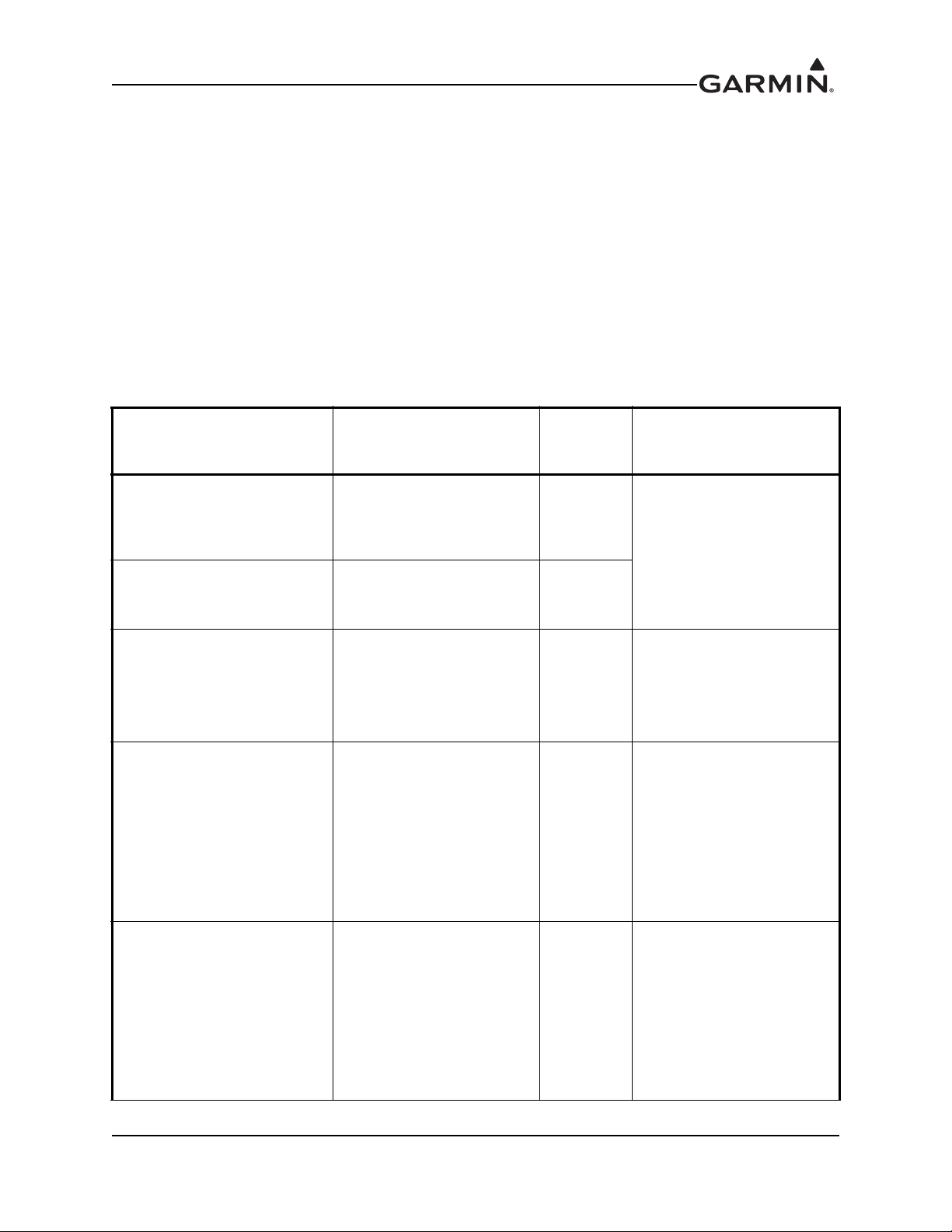
1.9.1 GTX 33 TSO/ETSO/RTCA/ICAO Compliance
Table 1-5 TSO/ETSO/RTCA/ICAO Compliance
Function
Air Traffic Control Radar
Beacon System/Mode Select
(ATCRBS/MODE S) Airborne
Equipment
Traffic Information Service
(TIS)
Air Traffic Control Radar
Beacon System/Mode Select
(ATCRBS/MODE S) Airborne
Equipment
Air Traffic Control Radar
Beacon System/Mode Select
(ATCRBS/MODE S) Airborne
Equipment
Performance Standard
(TSO/ETSO/RTCA/
EUROCAE)
TSO-C112 Class 2A
RTCA DO-239 -
ETSO-2C112a
ETSO-2C112a
Category
2C112b
Class 1
Level 2s
2C112b
Class 1
Level 2es
Applicable LRU SW Part
Numbers (See Note 4)
All
006-B0172-01 Rev. ()
except
006-B0172-01 Rev. A
(v1.00)
006-B0172-01
Rev. B (v3.00)
through
006-B0172-01
Rev. U (v5.01)
All
006-B0172-01 Rev. ()
except
006-B0172-01 Rev. A
(v1.00)
through
006-B0172-01 Rev. U
(v5.01)
All
006-B0172-01 Rev. ()
except
(v1.00)
through
(v3.06)
Enhanced Surveillance
ICAO Annex 10,
Amendment 77
Tables: 2-64, 2-80, 2-96
(See Note 1)
-
006-B0172-01 Rev. A
006-B0172-01 Rev. J
190-00906-00 GTX 33 Installation Manual
Rev. H Page 1-9
Page 22
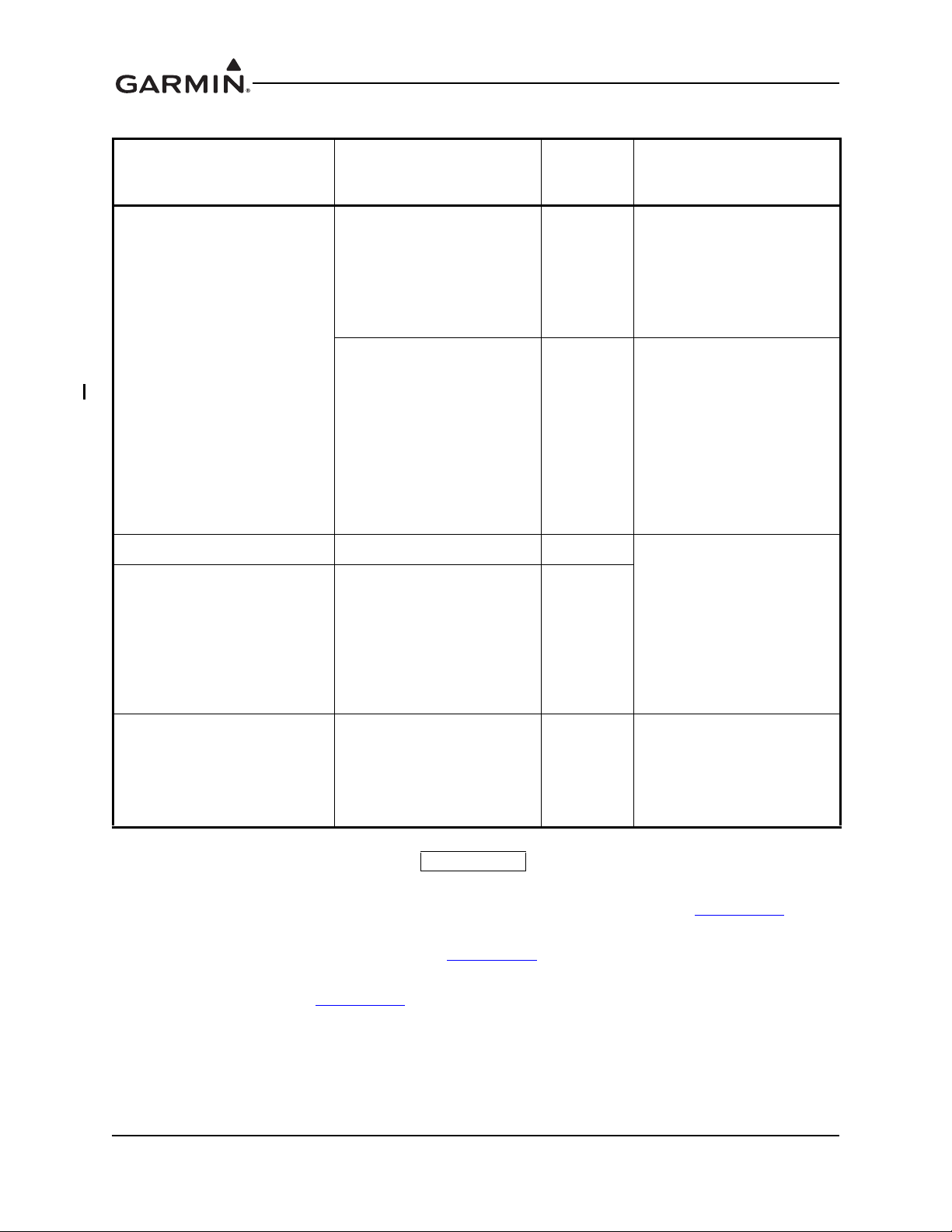
Table 1-5 TSO/ETSO/RTCA/ICAO Compliance
Performance Standard
Function
Extended Squitter Automatic
Dependent Surveillance –
Broadcast (ADS-B) and
Traffic Information Services –
Broadcast (TIS-B)
RTCA DO-178B Compliance DO-178B Level C All
RTCA DO-254 Compliance DO-254 Level C
(TSO/ETSO/RTCA/
EUROCAE)
TSO-C166a
ETSO-C166a
(See Note 2)
TSO-C166b
(See Note 3)
Category
B0 (nondiversity)
B1
(diversity)
B1S (non-
diversity)
B1
(diversity)
Applicable LRU SW Part
Numbers
All
006-B0172-01 Rev. V
(v6.00)
through
006-B0172-01 Rev. Z
(v6.20)
All
006-B0172-01 Rev. ()
(v7.01 or later)
except
006-B0172-01 Rev. A
(v1.00)
through
006-B0172-01 Rev. Z
(v6.20)
006-B0172-01 Rev. ()
except
006-B0172-01 Rev. A
(v1.00)
through
006-B0172-01 Rev. U
(v5.01)
006-B0172-01 Rev. A
(v1.00)
RTCA DO-178B Compliance DO-178B Level D
006-B0172-01 Rev. U
.
through
(v5.01)
NOTES
1. Complies with ICAO Annex 10, Amendment 77 Tables: 2-64, 2-80, 2-96 functionality only when
the Enhanced Surveillance function is enabled during configuration (refer to Section 3.7.1
).
2. Complies with TSO-C166a/ETSO-C166a functionality only when the Extended Squitter function
is enabled during configuration (refer to Section 3.7.1
).
3. Complies with TSO-C166b functionality only when the Extended Squitter function is enabled
during configuraton (Section 3.7.1
).
4. Software versions prior to 006-B0172-01 Rev. Z (v6.20) are not applicable to the GTX 33H/33DH.
GTX 33 Installation Manual 190-00906-00
Page 1-10 Rev. H
Page 23
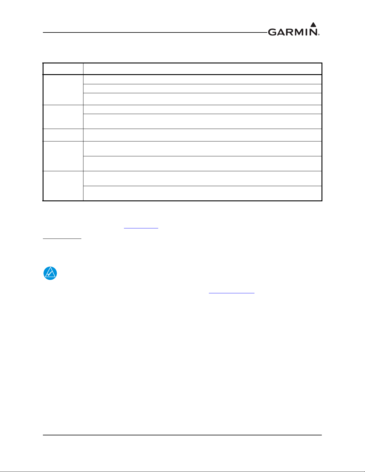
1.9.2 TSO/ETSO Deviations
NOTE
Table 1-6 TSO/ETSO Deviations
TSO/ETSO Deviation
1. Garmin was granted a deviation from TSO-C112 to use RTCA DO-178B instead of RTCA DO-178A.
TSO-C112
ETSO-2C112a
TSO-C166a 1. Garmin was granted a deviation from TSO-C166a to use RTCA DO-160D instead of RTCA DO-160E.
ETSO-C166a
TSO-C166b
2. Garmin was granted a deviation from TSO-C112 to use RTCA DO-160D instead of RTCA DO-160B.
3. Garmin was granted a deviation from TSO-C112 to use RTCA DO-181C instead of RTCA DO-181.
1. Garmin was granted a deviation from DO-160D, section 20.3.d.
2. Garmin was granted a deviation from ED-73B, section 1.4.2.2 to mark the equipment's functionallevel on the
chassis in a location not visible when the transponder is mounted in the aircraft.
1. Garmin was granted a deviation from ETSO-C166a to use RTCA/DO-160D instead of RTCA/DO- 160E as
the standard for Environmental Conditions and Test Procedures for Airborne Equipment.
2. Garmin was granted a deviation from ETSO-C166a, section 4.1 and 4.2 to reference the installation manual
for the equipment's ETSO compliance and class for this ETSO.
1. Garmin was granted a deviation from TSO-C166b to meet the transponder function requirements of RTCA
DO-181C instead of RTCA DO-181D.
2. Garmin was granted a deviation from TSO-C166b to use RTCA DO-160C instead of the latest revision of
RTCA DO-160.
1.10 Operating Instructions
For operating instructions, see Section 3.7.3 of this document.
Ident Function
:
Selecting the Ident function sends an ID indication to ATC for 18 seconds. This ID indication distinguishes
your transponder from all others on the air traffic controller’s radar screen.
For GX000 installations, refer to the applicable airframe specific pilot’s guide
documentation for operating instructions (available at www.garmin.com
).
190-00906-00 GTX 33 Installation Manual
Rev. H Page 1-11
Page 24

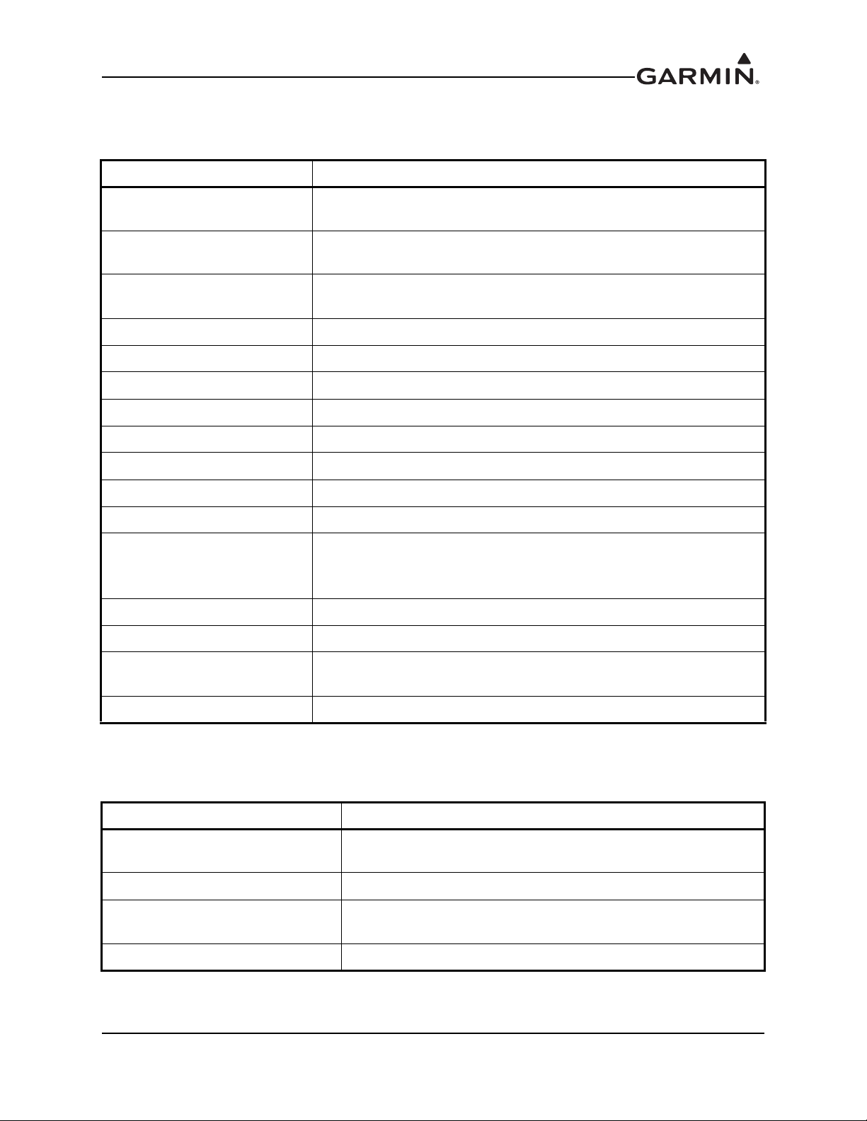
1.11 Reference Documents
The following publications are sources of additional information for installing the GTX 33. Before
installing the unit, the technician should read all relevant referenced materials along with this manual.
Table 1-7. GTX 33 Reference Documents
Part Number Document
190-00303-00 G1000 System Installation Manual
190-00303-04 G1000 Line Maintenance and Configuration Manual
560-1025-07 MX20 MFD Installation Manual
190-00607-04 GMX 200 Installation Manual
560-0982-01 GNS 480 (CNX80) Installation Manual
190-01004-02 GTN 625/635/650 TSO Installation Manual
190-01007-02 GTN 725/750 TSO Installation Manual
GTX 33 Installation Manual 190-00906-00
Page 1-12 Rev. H
Page 25

2 INSTALLATION OVERVIEW
2.1 Introduction
This section provides hardware equipment information for installing the GTX 33 Mode S Transponder,
related hardware and optional accessories. Installation of the GTX 33 should follow the data detailed in
this manual. Cabling is fabricated by the installing agency to fit each particular aircraft. The guidance of
FAA advisory circulars AC 43.13-1B and AC 43.13-2B, where applicable, may be found useful for
making retro-fit installations that comply with FAA regulations.
Refer to the G1000 System Installation Manual, Garmin part number 190-00303-00 for further details on
the mechanical aspects of the G1000 system rack. For installation in an aircraft using the remote mounted
stand-alone rack refer to Appendix C
2.2 Installation Materials
The GTX 33 is available as a single unit under the following part numbers:
Item Catalog Part Number Diversity
GTX 33, Unit Only, (011-00779-00) 010-00267-00 No
GTX 33 and Install Kit, (011-00779-00) 010-00267-01 No
GTX 33D, Unit Only (011-00779-01) 010-00294-00 Yes
for rack drawings and dimensions.
Table 2-1. GTX 33 Part Numbers
GTX 33D and Install Kit (011-00779-01) 010-00294-01 Yes
GTX 33, Unit Only (011-00779-10) 010-00267-10 No
GTX 33 and Install Kit (011-00779-10) 010-00267-11 No
GTX 33 w/ ES, Unit Only, (011-00779-20) 010-00267-20 No
GTX 33 w/ ES and Install Kit, (011-00779-20) 010-00267-21 No
GTX 33D w/ ES, Unit Only, (011-00779-21) 010-00294-20 Yes
GTX 33D w/ ES and Install Kit, (011-00779-21) 010-00294-21 Yes
GTX 33 w/ ES, Unit Only, (011-00779-30) 010-00267-30 No
GTX 33 w/ ES and Install Kit, (011-00779-30) 010-00267-31 No
GTX 33DH, Unit Only, (011-00779-41) 010-00294-40 Yes
GTX 33DH and Install Kit, (011-00779-41) 010-00294-41 Yes
GTX 33H, Unit Only (011-00779-50) 010-00267-50 No
GTX 33H and Install Kit (011-00779-50) 010-00267-51 No
GTX 33DH w/ ES, Unit Only, (011-00779-61) 010-00294-60 Yes
GTX 33DH w/ ES and Install Kit, (011-00779-61) 010-00294-61 Yes
GTX 33H w/ ES, Unit Only (011-00779-70) 010-00267-70 No
GTX 33H w/ ES and Install Kit (011-00779-70) 010-00267-71 No
190-00906-00 GTX 33 Installation Manual
Rev. H Page 2-1
Page 26

2.2.1 Equipment Available
Each of the following accessories is provided separately for the GTX 33 unit. Either rack and the
remainder of the accessories is required for installation.
Table 2-2. GTX 33 Accessories
Item Garmin Catalog Part Number
Modular Install Rack, GTX 33/GTX 33D
G1000 Nutplate Kit
Or
GTX 33/GTX 33D Stand-Alone Install Rack
(Alternate Configuration)
Or
GTX 33H/GTX 33DH Stand-Alone Install Rack
Connector Kit, GTX 33 011-01012-01 (Shield Block)
Back-plate Assembly, GTX 33
Back-plate Assembly, w/TNC, GTX 33
Back-plate Assembly, GTX 33D
(For use with GTX 33 and GTX 33D)
(For use with GTX 33 and GTX 33D)
(For use with GTX 33H and GTX 33DH)
115-00438-00
011-00915-01 (preferred)
or
011-01148-01
115-00629-00
011-02422-00
011-00582-00
(For use with GTX 33)
011-00582-04
(For use with GTX 33)
011-00582-01
(For use with GTX 33D)
Back-plate Assembly, w/TNC, GTX 33D
Back-plate Assembly, GTX 33H
Back-plate Assembly, GTX 33DH
Garmin Transponder Antenna kit*
(two required for diversity)
*Note: A transponder antenna approved to TSO C66( ) or C74( ) that has been installed to meet the
requirements of this manual may be used with the GTX 33.
011-00582-05
(For use with GTX 33D)
011-00582-02
(For use with GTX 33H)
011-00582-03
(For use with GTX 33DH)
010-10160-00
GTX 33 Installation Manual 190-00906-00
Page 2-2 Rev. H
Page 27

2.2.2 Additional Equipment Required
The following installation accessories are required but not provided:
• Cables – The installer will supply all system cables including circuit breakers. Cable requirements
and fabrication is detailed in Section 3 of this manual.
• Hardware – #6-32 x 100° Flathead SS Screw [(MS24693, AN507R or other approved fastener)
(4 ea.)] for horizontal mounting of the remote stand-alone rack.
• Hardware – #8-32 Panhead Machine Screw [(MS35206, AN526 or other approved fastener)
(4 ea.)] for vertical mounting of the remote stand-alone rack for GTX 33 and GTX 33D.
• Hardware – #8 x 100° Flathead Machine Screw [(see install drawing in Appendix C for more
detail) (4 ea.)] for mounting of the remote stand-alone rack for GTX 33H and GTX 33DH.
• Encoding Altitude Digitizer – For GNS 480 (CNX80), GTN 6XX/7XX, and GMX 200 (MX20)
installation. Use encoding altimeter manufacturer’s instructions. The Garmin GAE 43 (Garmin
P/N 013-00066-00) can provide altitude data in either serial or parallel gray code format.
2.3 Installation Considerations
In a Garmin Integrated Flight Deck, the GTX 33 interfaces with both GIA units. Optional available
discrete line interfaces are shown in Section 4.5
2.3.1 Preservation of Previous Systems
It is the installer’s responsibility to preserve the essential characteristic of the aircraft being modified with
this equipment to be in accordance with the aircraft manufacturer’s original design. This includes the
preservation of multiple power buses, which reduces the probability of interrupting power to essential
instruments and avionics.
Discrete Functions.
190-00906-00 GTX 33 Installation Manual
Rev. H Page 2-3
Page 28

2.3.2 Antenna Location Considerations
NOTE
Antenna mounting should utilize the aircraft manufacturer’s Type Certificated antenna location and style
of antenna. If a second (diversity) antenna is installed in the aircraft, considerations for its mounting should
be made as outlined in Figure 2-1
AC 43.12-2A Chapter 3. Note that penetration of the pressure vessel on the pressurized aircraft requires
additional data not contained in this manual. (Section 2.5
. The antenna installation should be installed in accordance with
)
Figure 2-1. Antenna Installation Considerations
• The antenna(s) (Garmin P/N 010-010160-00) or equivalent should be mounted away from major
protrusions, such as engine(s), propeller(s), and antenna masts. It should also be as far as practical
from landing gear doors, access doors, or other openings that could affect the radiation pattern.
• The main antenna should be mounted vertically on the bottom of the aircraft. The optional second
(diversity) antenna should be mounted vertically on top of the aircraft. Horizontal separation must
be no more than 7.6 meters (25 feet).
• Avoid mounting the antenna within three feet of the ADF sense antenna or any other
communication antenna and six feet from the DME antenna.
• To prevent RF interference, the antenna must be physically mounted a minimum distance of three
feet from the GTX 33.
If the antenna is being installed on a composite aircraft, sufficient ground plane material
must be added. Conductive wire mesh, radials, or thin aluminum sheets embedded in the
composite material provide the proper ground plane allowing the antenna gain pattern to
be maximized for optimum transponder performance.
GTX 33 Installation Manual 190-00906-00
Page 2-4 Rev. H
Page 29

2.4 Cabling and Wiring
Refer to the interconnect examples in Appendix D for wire gauge guidance.
For special installations that require the use of #18 or #20 AWG wire for power connections, the provided
connector kit supplies extended barrel contacts for AWG #18 wire. Special thin-wall heat shrink tubing is
also provided to insulate the extended barrels inside the backshell. If using #18 barrel contacts, ensure that
no two contacts are mounted directly adjacent to each other. This minimizes the risk of contacts touching
and shorting to adjacent pins and to ground. Ensure that routing of the wiring does not come in contact
with sources of heat, RF or EMI interference. Check that there is ample space for the cabling and mating
connectors. Avoid sharp bends in cabling and routing near aircraft control cables.
The GTX 33 and GTX 33D back-plate assemblies utilize BNC-type (bayonet connection) coaxial
connectors. The GTX 33H and GTX 33DH back-plate assemblies utilize TNC-type (threaded connection)
coaxial connectors.
The following table lists examples of the recommended antenna cable vendors and the type of cable to be
used for specific lengths of cable. Any cable meeting specifications is acceptable for the installation.
The maximum coaxial cable attenuation at 1090 MHz must not exceed 1.5 dB, including connectors. In the
diversity installation the cable loss characteristics must be the same within ±0.1 dB (cables within 4 inches
of the same length will have less than 0.1 dB difference in their loss characteristics).
The following table is for reference only, and lists some suitable cable types, along with the maximum
length based on an assumed loss figure of 0.2 dB per connector. Any 50 Ω, double shielded coaxial cable
assembly that meets airworthiness requirements and the 1.5 dB maximum loss figure (including
connectors) may be used.
Table 2-3. GTX 33 Cabling and Wiring
Max. Length
(feet - [m])
6’ 1.3” [1.86m] 18.0 M17/128-RG400 RG-400
7’ 7.3” [2.32m] 14.45 3C142B
9’ 2.0” [2.79m] 12.00 M17/112-RG304 RG-304
12’ 6.0” [3.81m] 8.80 311601 M17/127-RG393 RG-393
15’ 5.4” [4.71m] 7.12 311501
19’ 9.4” [6.03m] 5.56 311201
30’ 3.6” [9.24m] 3.63 310801
Supplier
Information
Insertion loss
(dB/100ft)
Carlisle IT Type MIL-C-17 Type RG Type
Vendor: Carlisle
Interconnect
Technologies
100 Tensolite Drive
St. Augustine, FL
32092
Tel: 800-458-9960
904-829-5600
Fax: 904-829-3447
www.carlisleit.com
See current issue
of Qualified
Products List
QPL-17
RG types are
obsolete and
are shown for
reference only;
replaced by
M17 type
numbers.
190-00906-00 GTX 33 Installation Manual
Rev. H Page 2-5
Page 30

2.4.1 Cable Routing Considerations
When routing antenna cables, observe the following precautions:
• All cable routing should be kept as short and as direct as possible
• Avoid sharp bends
• Avoid routing cables near power sources (e.g., 400 Hz generators, trim motors, etc.) or near power
for fluorescent lighting
• Avoid routing antenna cables near ADF antenna cable (allow at least a 12-inch separation)
2.5 Installation Approval Considerations for Pressurized Aircraft
Antenna and cable installations on pressurized cabin aircraft require FAA approved installation design and
engineering substantiation data whenever such installations incorporate alteration (penetration) of the
cabin pressure vessel by connector holes and/or mounting arrangements. Use of existing bulkhead
connectors previously approved by other means is permissible without additional approval.
For needed engineering support pertaining to the design and approval of such pressurized aircraft antenna
installations, it is recommended that the installer proceed according to any of the following listed options:
1. Obtain approved antenna installation design data from the aircraft manufacturer.
2. Obtain an FAA approved Supplemental Type Certificate (STC) pertaining to and valid for the
subject antenna installation.
3. Contact the FAA Aircraft Certification Office in the appropriate Region and request
identification of FAA Designated Engineering Representatives (DERs) who are authorized to
prepare and approve the required antenna installation engineering data.
4. Obtain FAA Advisory Circular AC-183C and select (and contact) a DER from the roster of
individuals identified thereunder.
5. Contact an aviation industry organization such as the Aircraft Electronics Association and request
their assistance.
2.6 Cooling Air
Refer to the G1000 System Installation manual, Garmin part number 190-00303-00, for information on
cooling requirements. For remote mounted units, forced air cooling is not required. However, the
application of forced air cooling is recommended to provide beneficial cooling if the unit is located in a
confined space or near a source of heat.
A 5/8 inch air fitting is provided on the rear of the backplate for the purpose of admitting cooling air under
such conditions. If a form of forced air cooling is installed, make certain that rainwater or condensation
cannot enter and be sprayed on the equipment.
GTX 33 Installation Manual 190-00906-00
Page 2-6 Rev. H
Page 31

2.7 GTX 33 Mounting Requirements
The GTX 33 mounting surface must be capable of providing structural support and electrical bond to the
aircraft to minimize radiated EMI and provide protection from High-Intensity Radiation Fields (HIRF).
The GTX 33 and GTX 33D can be mounted using the G1000 main system rack, or may be mounted
remotely if desired. Figure 2-2
system rack using the nutplate kit listed in Section 2.2.1
Assembly Drawing, for nutplate placement locations. The installer must provide any additional remote
mounting equipment.
2.7.1 Remote Mounted Stand-Alone Rack Considerations
shows the GTX 33 G1000 unit rack. The unit rack is fastened to the main
. Refer to Figure C-2, GTX 33 Connector/Rack
Figure 2-3
racks can be installed in a variety of locations, such as the electronics bay, under a seat or on an avionics
shelf behind the rear baggage area. Refer to Figure 2-5
between the GTX 33 and any obstruction. Install the rack in accordance with AC 43.13-2B Chapter 2
“Communication, Navigation, and Emergency Locator Transmitter System Installations”. The rack should
be mounted to a surface known to have sufficient structural integrity to withstand additional inertia forces
imposed by a 4.3-pound (1.95 kg) GTX 33 unit, rack, and connectors (see Section 1.7.1
information). If it is necessary to build a shelf or bracket to mount the GTX 33 stand-alone rack or it is not
certain that the chosen location is of sufficient structural integrity, refer to Appendix A for validation of
rack mounting structures and determining static load capability.
Figure C-3
vertically using four 8-32 pan head screws (MS35206, AN526 or other approved fastener). It can also be
mounted horizontally using four 6-32 100° counter-sunk flathead screws (MS24693, AN507R or other
approved fastener). Ensure that the GTX 33 chassis has a ground path to the airframe by having at least one
mounting screw in contact with the airframe. If more water-resistance is desired, the rack should be
installed in the upright vertical orientation only, otherwise, the rack may be mounted in either vertical or
horizontal orientation.
Figure 2-4
the stand-alone rack dimensions for the GTX 33H and GTX 33DH. The rack can be mounted in any
orientation using screws as defined in Section 2.2.2
the airframe by having at least one mounting screw in contact with the airframe. If more water-resistance is
desired, the rack should be installed in the upright vertical orientation only, otherwise, the rack may be
mounted in either vertical or horizontal orientation.
, Figure C-3, and Figure C-4show the GTX 33 remote mounted stand-alone racks. The remote
for suggested location. Leave sufficient clearance
for weight
gives the stand-alone rack dimensions for the GTX 33 and GTX 33D. The rack can be mounted
shows the stand-alone rack used for GTX 33H and GTX 33DH installations. Figure C-4 gives
. Ensure that the GTX 33 chassis has a ground path to
After the cable assemblies are made and wiring installed to the rack back plate, route wiring bundle as
appropriate. Use cable ties to secure the cable assemblies and coax to provide strain relief for the cable
assemblies.
190-00906-00 GTX 33 Installation Manual
Rev. H Page 2-7
Page 32

Figure 2-2. GTX 33 Modular Rack (115-00438-00)
Figure 2-3. GTX 33 Stand-Alone Rack (115-00629-00)
GTX 33 Installation Manual 190-00906-00
Page 2-8 Rev. H
Page 33

Figure 2-4. GTX 33H Stand-Alone Rack (011-02422-00)
190-00906-00 GTX 33 Installation Manual
Rev. H Page 2-9
Page 34

Figure 2-5. GTX 33 Stand-Alone Rack, Suggested Mounting Locations
GTX 33 Installation Manual 190-00906-00
Page 2-10 Rev. H
Page 35

3 INSTALLATION PROCEDURE
CAUTION
3.1 Unpacking Unit
Carefully unpack the equipment and make a visual inspection of the unit for evidence of damage incurred
during shipment. If the unit is damaged, notify the carrier and file a claim. To justify a claim, save the
original shipping container and all packing materials. Do not return the unit to Garmin until the carrier has
authorized the claim.
Retain the original shipping containers for storage. If the original containers are not available, a separate
cardboard container should be prepared that is large enough to accommodate sufficient packing material to
prevent movement.
3.2 Wiring Harness Installation
Allow adequate space for installation of cables and connectors. The installer shall supply and fabricate all
cables. All electrical connections to the GTX 33 are made through one 62-pin D-subminiature connector.
Section 4 defines the electrical characteristics of all input and output signals. Required connectors and
associated hardware are supplied with the connector kit.
See Appendix D
for examples of interconnect wiring diagrams. Construct the actual harnesses in
accordance with the aircraft manufacturer authorized interconnect standards.
Check wiring connections for errors before inserting the GTX 33 into the rack. Incorrect
wiring could cause internal component damage.
Table 3-1 Pin Contact Part Numbers (High Density)
Manufacturer*
18-20 AWG (Power Only) 22-28 AWG
Garmin P/N 336-00044-00 336-00021-00
Military P/N N/A M39029/58-360
*Non-Garmin part numbers shown are not maintained by Garmin and consequently are subject to
change without notice.
62 pin connector (P3301)
190-00906-00 GTX 33 Installation Manual
Rev. H Page 3-1
Page 36

Table 3-2 Recommended Crimp Tools (High Density)
18-20 AWG 22-28 AWG
Manufacturer
(note 1)
Military P/N M22520/2-01 N/A M81969/1-04 M22520/2-09 M81969/1-04
Positronic 9507-0 9502-11 M81969/1-04 9502-4 M81969/1-04
AMP 601966-1 N/A 91067-1 601966-6 91067-1
Daniels AFM8 K774 M81969/1-04 K42 M81969/1-04
Astro 615717 N/A M81969/1-04 615725 M81969/1-04
1) Non-Garmin part numbers shown are not maintained by Garmin and consequently are subject to
change without notice.
2) Extracting the #18 or #20 contact requires that the expanded wire barrel be cut off from the contact.
It may also be necessary to push the pin out from the face of the connector when using an extractor due
to the absence of the wire. A new contact must be used when reassembling the connector.
Hand Crimp-
ing Tool
Positioner
Insertion/
Extraction Tool
(note 2)
Positioner
Insertion/
Extraction
Tool
Table 3-3. Recommended Crimp Tools
18-20 AWG 22-28 AWG
Manufacturer
(Note 1)
Military P/N M22520/2-01 N/A M81969/1-04 M22520/2-09 M81969/1-04
Positronic 9507 9502-11 M81969/1-04 9502-3 M81969/1-04
AMP 601966-1 N/A 91067-1 601966-6 91067-1
Daniels AFM8 K774 M81969/1-04 K42 M81969/1-04
Astro 615717 N/A M81969/1-04 615725 M81969/1-04
Hand
Crimping Tool
Positioner
(Note 3)
Insertion/
Extraction Tool
(Note 2)
Positioner
Insertion/
Extraction
Tool
NOTES
1. Non-Garmin part numbers shown are not maintained by Garmin and consequently are subject to
change without notice.
2. Extracting the 18 AWG contacts requires that the expanded wire barrel be cut off from the contact.
It may also be necessary to push the pin out from the face of the connector when using an extractor
due to the absence of the wire. A new contact must be used when reassembling the connector.
GTX 33 Installation Manual 190-00906-00
Page 3-2 Rev. H
Page 37

3.3 Backshell Assembly
NOTE
The GTX 33 connector kit includes one Garmin backshell assembly. Garmin’s backshells give the installer
the ability to quickly and easily terminate shield grounds at the backshell housing using one of two
methods available (SPIDER or Shield Block).
The SPIDER grounding method is permitted for previous installations, however Garmin
recommends the use of the Shield Block grounding method for all new installations.
G1000 Installations:
To assemble the backshell and grounding system, refer to the instructions provided in the G1000 System
Installation Manual (190-00303-00), as well as the SPIDER Installation Instructions (190-00313-03) and
Shield Block Installation Instructions (190-00313-09).
Non-G1000 Installations:
GTX 33 installations mounted as a remote transponder system, the connector and backshell assembly is
shown below. Refer to the SPIDER Installation Instructions (190-00313-02) and Shield Block Installation
Instructions (190-00313-09) for grounding instructions.
1. Backshell Cast Housing. Provides a mounting point for connector accessories.
2. D-Subminiature 62 pin connector.
3. Ground System (SPIDER ground shown). Allows shield grounds to be made to the backshell
housing.
4. Strain Relief Tab. Fastens wiring bundle to housing.
190-00906-00 GTX 33 Installation Manual
Rev. H Page 3-3
Page 38

5. Backshell Lid. Provides access when servicing the connector.
3
4
5
2
1
Figure 3-1. Backshell Connector Assembly
(Top: Exploded View. Bottom: Assembled.)
GTX 33 Installation Manual 190-00906-00
Page 3-4 Rev. H
Page 39

3.4 Weight and Balance
CAUTION
CAUTION
Weight and balance computation is required after the installation of the GTX 33. Follow the guidelines as
established in AC 43.13-1B, Chapter 10, Section 2. Make appropriate entries in the equipment list
indicating items added, removed or relocated along with the date accomplished. Include your name and
certificate number in the aircraft records. Section 1.7.1
and Figure C-1 in Appendix C shows the center of gravity.
identifies the weight of the new GTX 33 equipment
3.5 Electrical Load Analysis
An electrical load analysis should be completed on each aircraft prior to installation in accordance with
AC43.13-1B, Chapter 11. Use the following values for computation:
Table 3-4. Unit Power Loads
GTX 33 Input
Typical Max. Typical Max.
GTX 33 Main Power 1.6 A 3.1 A 0.85 A 1.6 A
14 VDC 28 VDC
3.6 Final Installation
For final installation and assembly, refer to the outline and installation drawings shown in Appendix C of
this manual.
1. Assemble the connector backshell as described in Section 3.3
2. Attach the connector to the rear plate using the screws provided in the connector kit.
3. Mount the unit rack to the main system rack or other suitable mounting location using the provided
nutplates or installer supplied screws.
4. Assemble the rear plate into the GTX 33 unit rack using screws provided with the rear plate.
5. Insert the GTX 33 into the rack, noting proper orientation as shown on the installation drawing in
Appendix C.
Do not use excessive force when inserting the GTX 33 into the rack. This may cause
damage to occur to the connectors, unit, and/or unit rack. If heavy resistance is felt during
installation, stop! Remove the GTX 33 and identify the source of resistance.
.
190-00906-00 GTX 33 Installation Manual
Rev. H Page 3-5
6. GTX 33/33D Only: Lock the GTX 33/33D in place using the lever-locking handle. Fasten the handle to the GTX 33/33D body using the provided Phillips screw. (Note that some early GTX 33/
33D units use a D-ring ¼-turn fastener)
Start the handle screw into the hole carefully, to avoid cross-threading. Do not apply
torque in excess of 14 in-lbs to the handle screw. The application of torque exceeding
14 in-lbs to the screw will damage the LRU case and/or retaining hardware.
7. GTX 33H/33DH Only: Lock the GTX 33H/33DH in place using the install screw. Tighten the
screw until the connectors are fully mated and the retaining wedge in the rack is fully mated with
the wedge attached to the unit. Tighten to the torque specification shown in Appendix C
.
Page 40

3.7 Post Installation Configuration and Checkout
NOTE
The GTX 33 Mode S Transponder will not provide valid outputs until the aircraft post
installation configuration procedures are completed.
3.7.1 Configuration
When installed as part of the Garmin Integrated Flight Deck, the GTX 33 transponder must have FAA
approved configuration data. Configuration data is loaded to the GTX 33 from an aircraft-specific
Software Loader Card. Transponder settings are predetermined for a specific aircraft and are typically
contained within the file named ‘GTX1’. However, the aircraft registration number must be entered
manually.
The PFD serves as the graphics user interface to the installer configuring the system. For basic
configuration information, refer to the G1000 Line Maintenance and Configuration Manual, Garmin part
number 190-00303-04. For actual aircraft installation/checkout, use only aircraft manufacturer approved
checkout procedures.
Verify proper operation of the transponder by testing in accordance with Appendix F to 14 CFR Part
43 – ATC Transponder Tests and Inspections.
For transponder installations operating with a Garmin GNS 480 (CNX80), refer to GNS 480 (CNX80)
Installation Manual, 560-0982-01 for configuration procedures and operation checks.
For transponder installations operating with a Garmin GTN 6XX/7XX, refer to the GTN 625/635/650 TSO
Installation Manual (190-01004-02) or the GTN 725/750 TSO Installation Manual (190-01007-02) for
configuration procedures and operation checks.
3.7.2 Interference Check
Turn on and verify operation of all avionics equipment except GTX 33. Then power GTX 33 on and verify
there is no interference with any other equipment in the aircraft. The operation/performance checks should
be made with all other avionics turned on. Verify that there is no interference during any mode of
transponder operation.
GTX 33 Installation Manual 190-00906-00
Page 3-6 Rev. H
Page 41

3.7.3 Operation/Performance Checkout
CAUTION
If the unit is removed from the aircraft and operated, always connect J3302, (and J3303
for GTX 33D) to an antenna or a 50 Ω, 5-Watt load. The GTX 33 transmits Mode S
acquisition squitter replies about once per second whether interrogations are received or
not.
Verify proper operation of the transponder by testing as specified in Appendix F of 14 CFR, Part 43, to
AC 43-6B, and/or other appropriate regulations. The test is typically done as a ramp test using a
transponder ramp test set, such as the TIC TR-220, IFR ATC-601 or other suitable Mode S transponder test
set.
Self Test
Verify that the unit does not display a failure indication when turned on.
Altitude Input
Verify that the displayed altitude matches pressure altitude (at 29.92).
External Inputs
If the external ident or standby inputs are connected, verify operation by:
a) Verify that the unit goes to standby when the external standby input is pulled low.
b) Verify that the ident indication turns on when the external ident button is pressed (must be in
the “ON” or “ALT” modes.
3.7.4 Performance (Ramp) Test
After installation, the transponder should be tested as specified in 14 CFR Part 43 Appendix F, AC 43-6B,
and other appropriate regulations. The test is typically done as a ramp test using a transponder ramp test
set, such as the IFR ATC-601A. The ramp test includes checks as follows:
Reference Part 43 Appendix F:
a) Reply Frequency
b) Suppression
c) Receiver Sensitivity
d) Reply RF Output Power
e) Mode S Diversity Channel Isolation (if applicable)
f) Mode S Address
g) Mode S Formats
h) Mode S All-Call
i) ATCRBS - Only All Call
j) Squitter
Reference AC 43-6B and 14 CFR Part 43, Appendix E (c):
Altitude Reporting
190-00906-00 GTX 33 Installation Manual
Rev. H Page 3-7
Page 42

3.8 Continued Airworthiness
Test according to Title 14 CFR §§ 91.411 and 91.413 as well as Part 43 Appendix F. Other than for
regulatory checks, maintenance of the GTX 33 is ‘on condition’ only.
GTX 33 Installation Manual 190-00906-00
Page 3-8 Rev. H
Page 43

4 SYSTEM INTERCONNECTS
4.1 Pin List
4.1.1 P3301 Connector
Figure 4-1. View of J3301 connector from back of unit
Table 4-1. P3301 Pin List
Pin Pin Name I/O
1 RESERVED In
2 ALTITUDE A1 In
3 ALTITUDE C2 In
4 ALTITUDE A2 In
5 ALTITUDE A4 In
6 ALTITUDE C4 In
7 ALTITUDE B1 In
8 ALTITUDE C1 In
9 ALTITUDE B2 In
10 ALTITUDE B4 In
11 ALTITUDE D4 In
12 EXTERNAL IDENT SELECT* In
13 EXTERNAL STANDBY SELECT* In
14 NOT USED In
15 AUDIO OUT HI Out
16 AUDIO OUT LO Out
17 SQUAT SWITCH IN In
18 RESERVED --
19 ALTITUDE ALERT ANNUNCIATE* Out
20 RESERVED --
21 AIRCRAFT POWER 1 In
*Indicates Active Low (Ground to activate)
190-00906-00 GTX 33 Installation Manual
Rev. H Page 4-1
Page 44

Table 4-1. P3301 Pin List
Pin Pin Name I/O
22 RS-232 IN 1 In
23 RS-232 OUT 1 Out
24 RS-232 IN 2 In
25 RS-232 OUT 2 Out
26 ARINC 429 IN 3 A In
27 POWER GROUND --
28 ARINC 429 OUT 2 B Out
29 ARINC 429 IN 3 B In
30 ARINC 429 OUT 2 A Out
31 EXTERNAL SUPPRESSION I/O I/O
32 ARINC 429 IN 1 A In
33 ARINC 429 IN 2 A In
34 ARINC 429 OUT 1 B Out
35 ARINC 429 IN 1 B In
36 ARINC 429 IN 2 B In
37 ARINC 429 OUT 1 A Out
38 RESERVED --
39 RESERVED --
40 SPARE --
41 CURRENT TEMPERATURE PROBE OUT Out
42 AIRCRAFT POWER 1 In
43 POWER GROUND --
44 CURRENT TEMPERATURE PROBE IN In
45 NOT USED In
46 TIS CONNECT SELECT* In
47 AUDIO MUTE SELECT* In
48 ARINC 429 IN 4 A In
49 ARINC 429 IN 4 B In
50 ALTITUDE COMMON (GROUND) In
51 SIGNAL GROUND --
52 RESERVED --
*Indicates Active Low (Ground to activate)
GTX 33 Installation Manual 190-00906-00
Page 4-2 Rev. H
Page 45

Table 4-1. P3301 Pin List
Pin Pin Name I/O
53 RESERVED --
54 XPDR REMOTE POWER OFF In
55 NOT USED --
56 AIRCRAFT POWER 2 In
57 NOT USED --
58 SIGNAL GROUND --
59 NOT USED --
60 AIRCRAFT POWER 2 In
61 NOT USED --
62 SWITCHED POWER OUT Out
*Indicates Active Low (Ground to activate)
4.2 Power Functions
Power Input requirements are listed in the following tables. The power-input pins accept 14/28 Vdc.
Switched Power Out is a power source available for devices such as a remote digital altitude encoder.
Refer to Figure D-1
and Figure D-2 for power interconnections.
4.2.1 Aircraft Power
Table 4-2. Aircraft Power
Pin Name Connector Pin I/O
AIRCRAFT POWER 1 P3301 21 In
AIRCRAFT POWER 1 P3301 42 In
AIRCRAFT POWER 2 P3301 56 In
AIRCRAFT POWER 2 P3301 60 In
SWITCHED POWER OUT P3301 62 Out
XPDR REMOTE POWER OFF P3301 54 In
POWER GROUND P3301 27 --
POWER GROUND P3301 43 --
SIGNAL GROUND P3301 51 --
SIGNAL GROUND P3301 58 --
190-00906-00 GTX 33 Installation Manual
Rev. H Page 4-3
Page 46

4.3 Temperature Inputs
NOTE
Temperature function with pin assignments are shown for reference since the temperature function is
available in the GTX 33. In the Garmin Integrated Flight Deck system, temperature data is received from
the GIA 63 in RS-232 format.
Table 4-3. Temperature Inputs
Pin Name Connector Pin I/O
CURRENT TEMPERATURE PROBE OUT P3301 41 Out
CURRENT TEMPERATURE PROBE IN P3301 44 In
Temperature function is provided for the external display system via input to the GTX 33 transponder. The
Temperature input is used for Outside Air Temperature (OAT) display and Density Altitude computations.
The type of temperature probe required is a current sensor type, such as a Garmin GTP 59 or an
AD590-KH or AD592 made by Analog Devices. The GTX 33 is not configurable for different types of
temperature sensors. The temperature-input specification is 1 micro amp per degree Kelvin (1 uA/°K).
4.4 Altitude Functions
Altitude functions with pin assignments are shown for reference since the altitude function is available in
the GTX 33. In the Garmin Integrated Flight Deck system, altitude data is received from the GIA 63 in
RS-232 format.
Parallel gray code altitude inputs are considered active if either the voltage to ground is < 1.9 V or the
resistance to ground is < 375 Ω. These inputs are considered inactive if the voltage to ground is 11-33 Vdc.
The GTX 33 contains internal altitude code line isolation diodes to prevent the unit from
pulling the encoder lines to ground when the transponder is turned off.
If two separate altitude encoders are connected to the GTX 33, one providing parallel
gray code and the other, serial data, the unit selects only one for use at a time, with serial
data input receiving the highest priority.
For altitude encoders that can be connected in both serial data and parallel gray code
format, such as the Garmin GAE 43 (Garmin P/N 013-00066-00), select one or the other
but not both wiring connections.
When connecting two GTX 33 transdponders to a Garmin GNS 480 (CNX80), the unit can
only receive serial data from one transponder at a time. Use a DPDT switch to connect
both serial data and External Standby Select. Refer to Figure D-4
Among the surveillance items the Mode S transponder will transmit to the ground stations and other
aircraft are altitude reporting in 25-foot increments with the proper encoder. In order to report altitude in
25-foot increments the GTX 33 must receive altitude from suitable altitude reporting devices through serial
input connections. Altitude input to the GTX 33 received from parallel wire gray code encoders is supplied
to the unit in 100-foot increments and thus reported in 100-foot increments.
.
GTX 33 Installation Manual 190-00906-00
Page 4-4 Rev. H
Page 47

4.4.1 Altimeter Inputs
Table 4-4. Altimeter Inputs
Pin Name Connector Pin I/O
ALTITUDE D4 P3301 11 In
ALTITUDE A1 P3301 2 In
ALTITUDE A2 P3301 4 In
ALTITUDE A4 P3301 5 In
ALTITUDE B1 P3301 7 In
ALTITUDE B2 P3301 9 In
ALTITUDE B4 P3301 10 In
ALTITUDE C1 P3301 8 In
ALTITUDE C2 P3301 3 In
ALTITUDE C4 P3301 6 In
ALTITUDE COMMON P3301 50 --
4.4.2 Altimeter Interconnect, Dual GTX 33 Installation
For complete dual installation in which digital altitude encoders are connected to the GTX 33, it is best to
install two digital sources, connecting one encoder to each transponder.
4.4.3 Altimeter Selection Priority
When connecting the transponder to a GNS 480 (CNX80) or GTN 6XX/7XX the installer must be aware
of the GTX 33 priority for selecting encoded altimeter interconnections. The GTX 33 searches in this
sequence for altitude, and stops when it finds a valid pressure altitude input.
Altitude reporting equipment order of precedence:
1. ARINC 429 Air Data Computer (label 203, if configured W/ALT) (25’)
2. ARINC 429 EFIS (label 203, if configured W/ALT) (25’)
3. RS-232 data from GNS 480 (CNX80), GTN 6XX/7XX, or Garmin Integrated Flight Deck (25')
4. RS-232 Fuel/Air Data Computer (if configured W/ALT.) (25’)
5. Shadin Altitude Serializer/Encoder (if configured for 25’)
6. Icarus Altitude Serializer/Encoder (if configured for 25’)
7. Parallel wire Gray Code input (100’)
8. Shadin Altitude Serializer/Encoder (if configured for 100’)
9. Icarus Altitude Serializer/Encoder (if configured for 100’)
Only approved devices may provide altitude to the GTX 33 in accordance with 14 CFR 91.217. In
addition, all altitude reporting devices installed in the aircraft must meet certification requirements of
14 CFR 91.413. The installer must select an altitude reporting device that is a certified altitude source for
the particular aircraft.
It is the installing agency’s responsibility to determine that the installed encoder is compatible with the
selected altitude reporting criteria, either 100’ or 25’. Refer to the GNS 480 (CNX80) Installation Manual
or the appropriate GTN 6XX/7XX Installation Manual for the altitude data reporting configuration.
190-00906-00 GTX 33 Installation Manual
Rev. H Page 4-5
Page 48

4.5 Discrete Functions
Discrete functions with pin assignments are shown for reference since the functions are available in the
GTX 33. External suppression should be connected if another transponder or DME is installed in the
aircraft avionics system. Depending on system configuration, the Garmin Integrated Flight Deck may not
use these inputs, as many functions are received from the GIA 63 in RS-232 format.
4.5.1 Discrete Outputs
External suppression should be connected if a DME is installed in the aircraft avionics system. The
GTX 33 suppression I/O pulses may not be compatible with all models of DME. Known incompatible
units include the Bendix/King KN 62, KN 64 and KNS 80. These models have an output-only suppression
port and can be damaged by the GTX 33 mutual suppression output. In this case, leave the suppression pin
open.
Table 4-5. Discrete Outputs
Pin Name Connector Pin I/O
ALTITUDE ALERT ANNUNCIATE* P3301 19 Out
EXTERNAL SUPPRESSION I/O (TXP/DME) P3301 31 I/O
SIGNAL GROUND P3301 51 --
SIGNAL GROUND P3301 58 --
*
INACTIVE: 10 ≤ Vin ≤ 33VDC or Rin ≥100kΩ
ACTIVE: Vin ≤ 1.9VDC with ≥ 75 uA sink current, or Rin ≤ 375Ω
Sink current is internally limited to 200 uA max for a grounded input
4.5.2 DISCRETE INPUTS
Table 4-6. Discrete Inputs
Pin Name Connector Pin I/O
EXTERNAL IDENT SELECT* P3301 12 In
EXTERNAL STANDBY SELECT* P3301 13 In
SQUAT SWITCH IN P3301 17 In
TIS CONNECT SELECT* P3301 46 In
AUDIO MUTE SELECT* P3301 47 In
*
INACTIVE: 10 ≤ Vin ≤ 33VDC or Rin ≥100kΩ
ACTIVE: Vin ≤ 1.9VDC with ≥ 75 uA sink current, or Rin ≤ 375Ω
Sink current is internally limited to 200 uA max for a grounded input
EXTERNAL IDENT SELECT (remote IDENT) is a momentary input. Refer to the GNS 480 (CNX80) or
the appropriate GTN 6XX/7XX Installation Manual for remote ident configuration.
EXTERNAL STANDBY SELECT (remote STANDBY) is used when two GTX 33 systems are installed
in an aircraft. Refer to Figure D-4, for the EXTERNAL STANDBY SELECT interconnect. When
GTX 33 Installation Manual 190-00906-00
Page 4-6 Rev. H
Page 49

EXTERNAL STANDBY SELECT is grounded, ARINC 429 OUT PORT 1 remains active, while PORT 2
is inactive.
When TIS is inactive, the GTX 33 logs onto TIS service when a momentary ground is applied to
P3301-46. When TIS is active, a momentary ground logs off of TIS service. Refer to the GNS 480
(CNX80) Installation Manual, MX20 Installation Manual, or appropriate GTN 6XX/7XX Installation
Manual for TIS configuration.
An AUDIO MUTE SELECT mute switch may be used to control TIS audio alerts. TIS (Traffic) Mute
must be clearly marked with MUTE ON/MUTE OFF or TIS Audio ON/Audio OFF labels. The muting
feature may be enabled through a Multi-Function display. In order to prevent inadvertent muting, the status
of muting must default to "Mute off" upon each power cycle. Refer to the GNS 480 (CNX80) Installation
Manual or appropriate GTN 6XX/7XX Installation Manual for AUDIO configuration.
4.6 Serial Data Electrical Characteristics
The GTX 33 manages support for several equipment interfaces. The GTX 33 can be configured to include
GPS, Airdata, AHRS, EFIS/Airdata, and ADLP 429 inputs, functioning as an ARINC 429 data
concentrator.
The GTX 33 has four ARINC 429 input ports, making it capable of taking altitude, air data, heading, EFIS
selected course and possible future features, and then concentrating it on the ARINC 429 OUT 2 ports for
possible data link applications.
The GTX 33 is designed to feed all outgoing data to the external display via RS-232 data ports.
4.6.1 RS-232 Input/Output
Table 4-7. RS-232 Input/Output
Pin Name Connector Pin I/O
RS-232 OUT 1 P3301 23 Out
RS-232 IN 1 P3301 22 In
RS-232 OUT 2 P3301 25 Out
RS-232 IN 2 P3301 24 In
SIGNAL GROUND P3301 51 --
SIGNAL GROUND P3301 58 --
The RS-232 outputs conform to EIA Standard RS-232C with an output voltage swing of at least ±5 V
when driving a standard RS-232 load. Refer to figures in Appendix D
for the RS-232 serial data
interconnect.
When connecting two GTX 33 transponders to a GPS, the unit can only receive RS-232 serial data from
one unit at a time. Use a DPDT switch for connecting both serial data and External Standby Select. Refer
to Figure D-4
.
190-00906-00 GTX 33 Installation Manual
Rev. H Page 4-7
Page 50

4.6.2 ARINC 429 Input/Output
Table 4-8. ARINC 429 Channels
Pin Name Connector Pin I/O
ARINC 429 OUT 1A P3301 37 Out
ARINC 429 OUT 1B P3301 34 Out
ARINC 429 IN 1A P3301 32 In
ARINC 429 IN 1B P3301 35 In
ARINC 429 IN 2A P3301 33 In
ARINC 429 IN 2B P3301 36 In
ARINC 429 OUT 2A P3301 30 Out
ARINC 429 OUT 2B P3301 28 Out
ARINC 429 IN 3A P3301 26 In
ARINC 429 IN 3B P3301 29 In
ARINC 429 IN 4A P3301 48 In
ARINC 429 IN 4B P3301 49 In
SIGNAL GROUND P3301 51 --
SIGNAL GROUND P3301 58 --
The ARINC 429 outputs conform to ARINC 429 electrical specifications when loaded with up to five
standard ARINC 429 receivers.
The following data is sent out at specified intervals using high speed ARINC 429 (100 kHz). The transmit
data labels and their rates are as follows:
Table 4-9. ARINC Labels
Label Data Rate
100 Selected Course (degrees) 200 ms
203 Pressure Altitude [in feet set to 29.92” Hg (1013.25 mb)] 100 ms
204 Barometric Corrected Altitude (feet) 100 ms
206 Indicated Air Speed (knots) 100 ms
210 True Air Speed (knots) 100 ms
211 Total Air Temperature (degrees) 100 ms
213 Static Air Temperature (degrees) 100 ms
306 Joystick Lat 500 ms
307 Joystick Lon 500 ms
314 True Heading 100 ms
320 Magnetic Heading (Degrees) 100 ms
371 GA Equipment Identifier 500 ms
377 Equipment Identifier 500 ms
GTX 33 Installation Manual 190-00906-00
Page 4-8 Rev. H
Page 51

4.7 RS-232 Input/Output, Software Update Connections
NOTE
CAUTION
When the GTX 33 is installed in a system other than a Garmin Integrated Flight Deck an optional RS-232
serial data connector should be installed in the aircraft for future software upgrades, negating the need to
remove the transponder from the aircraft. The connector can be mounted anywhere convenient for access,
such as under the instrument panel, on a remote avionics shelf next to the unit or in the instrument panel
itself. Be sure to label the connector for Software Update. Do not include the Test Mode Select switch in
the aircraft. See Figure 4-2
If the GTX 33 installation interfaces with a GNS 480 (CNX80) in the aircraft, the GNS 480 (CNX80) must
be turned off during GTX 33 software upload, due to loading of RS-232 port 1.
The installation of an optional software upgrade connector is highly recommended. If the
connector is wired in the aircraft, transponder removal and reinstallation for software
upgrade is not required.
If the unit is removed from the aircraft and operated, always connect J3302, (and J3303
for GTX 33D) to an antenna or a 50 Ω, 5-Watt load. The GTX 33 transmits Mode S
acquisition squitter replies about once per second whether interrogations are received or
not.
for software update connections.
Beginning with software version 3.06, the GTX 33 software can be updated in the Configuration mode as
well as in Test mode. Updating software in Configuration mode does not require the TEST MODE
SELECT switch.
Figure 4-2. GTX 33 Software Update Connections
190-00906-00 GTX 33 Installation Manual
Rev. H Page 4-9
Page 52

This page intentionally left blank
GTX 33 Installation Manual 190-00906-00
Page 4-10 Rev. H
Page 53

APPENDIX A CONSTRUCTION AND VALIDATION OF STRUCTURES
A.1 Static Test Loading
This appendix includes information necessary for testing load-carrying capabilities of equipment mounting
structures, such as shelves, mounting plates and mounting brackets, used to mount the GTX 33 remote
mounting tray.
Baggage compartments and cabins or cockpit floors are good mounting platforms providing the floor
attachments meet the strength requirements. If support racks, brackets or shelves need to be fabricated,
they should be fabricated and attached to the aircraft structure in accordance with the methods outlined in
AC 43.13-2B Chapter 2. After the structure is installed, it should be tested as outlined in AC 43.13-2B
Chapter 1 to verify that it is capable of supporting the required loads.
The GTX 33 installation must be capable of withstanding the Ultimate Load Factors listed in Table A-1 for
at least 3 seconds in each direction specified without damage or permanent deformation. Note that these
required loads differ somewhat from those normally required for equipment installations.
Since the combined weight of the GTX 33 and its equipment mounting rack and connector is 4.3 lbs, the
static loads which must be applied (Load Factor x 4.3 lbs.) will be as follows:
Table A-1. Static Test Load
Direction of Force Load Factor
DOWNWARD 6.6 G (6.6 x 4.3) = 28.4 lbs
UPWARD 6.0 G (6.0 x 4.3) = 25.8 lbs
SIDEWAYS 4.5 G (4.5 x 4.3) = 19.4 lbs
FORWARD 18.0 G (18.0 x 4.3) = 77.4 lbs
(Load Factor x GTX 33 weight)
Static Test Load
A.2 Determining Static Load Capability
A recommended method of determining the static load capability is as follows:
1. Mark and drill the holes where the GTX 33 equipment rack will be mounted.
2. Install four 8-32 machine screws (MS35206, AN526 or other approved fastener) in the four holes
which will be used to mount the GTX 33 equipment rack using washers, nuts and nutplates to
mount the equipment rack to the mounting surface. Note that some means of locking fastener must
be used, e.g. either lock nuts or steel nuts with lock washers.
3. For testing downward loading, place shot bags or other suitable weights totaling 28.4 pounds
within the footprint outlined by the four screw holes (assuming the mounting surface is horizontal)
or use a calibrated force gauge at the location of the center of gravity when the unit is mounted.
4. Verify there is no damage or permanent deformation of the structure after 3 seconds.
5. Fasten a 36 inch loop of suitable material such as fishing line, braided wire, or other similar
material having a breaking strength of at least 100 lbs., diagonally between two of the screws.
Then fasten another loop diagonally between the other two screws, adjusting the length of the loop
so it exactly matches the first.
190-00906-00 GTX 33 Installation Manual
Rev. H Page A-1
Page 54

6. Hook a calibrated force gauge through both loops and apply a sustained pull for at least 3 seconds
in each of the other three directions (upward, sideward and forward) at the above calculated forces
(i.e. 25.8 lb. upward, 19.4 lb. sideward and 77.4 lb. forward).
7. Examine the support structure carefully. If there has been damage or permanent deformation, the
structure is not suitable and must be replaced with one that is strong enough to withstand the test
loads. Examine all aircraft stringers, bulkheads and skin surfaces, which may have direct or
indirect contact with the fabricated shelf. If it is determined that no damage or permanent
deformation has occurred, the structure is of sufficient strength and the GTX 33 equipment rack
may be permanently mounted on it.
Figure A-1. Upward Static Load Test
Figure A-2. Forward Static Load Test
GTX 33 Installation Manual 190-00906-00
Page A-2 Rev. H
Page 55

APPENDIX B VERSION 1 ADS-B FIELD APPROVAL COMPLIANCE
MATRIX
This section provides a compliance matrix template which installers may use to obtain field approvals for
the activation of the GTX 33 ADS-B Extended Squitter function, as described in Section 1.3
provides a break-down of EASA AMC 20-24 requirements and corresponding compliance statements.
For installations that utilize a Garmin GNS 480 or GTN 6XX/7XX device (collectively referred to as
‘Garmin GNS/GTN equipment’), no additional data is required for the compliance matrix. Compliance
statements are pre-populated for all aspects involving GNSS position source requirements.
If a non-Garmin GPS position source is used, the installer must:
1. Determine the GPS position source is compliant with the ARINC 743A standard
2. Obtain and input the appropriate data into the compliance matrix:
a) Item 14, Horizontal Position and Horizontal Position Quality Indicator(s)
b) Item 17, Horizontal Position Source Accuracy
c) Item 18, Horizontal Position Source Integrity
d) Item 19, Horizontal Position Source Integrity - Source Failure Probability
. The table
e) Item 20, Horizontal Position Source Integrity - Alert Failure Probability
f) Item 21, Horizontal Position Source Integrity - Time to Alert
g) Item 26, GPS Engine and GPS processing design assurance levels
h) Item 28, Horizontal position data latency requirements
i) Item 53, Position source minimum requirements
j) Item 55, Alternative means of establishing integrity containment radius (if not provided by
the horizontal position data source)
k) Item 58, GNSS position source TSO compliance
l) Item 59, Identify whether the system incorporates Fault Detection and Exclusion capability
as defined in AC 20-138A
m) Item 60, Identify use of Alternative Compliant Position Data Sources, if equipped
n) Item 61, Identify use of Temporary Back-up Position Data Sources, if equipped
o) Item 75, Ground Velocity
190-00906-00 GTX 33 Installation Manual
Rev. H Page B-1
Page 56

Table B-1. Version 1 ADS-B Field Approval Compliance Matrix
Item #
1. 7.0 Functional Criteria
2. 7.1
3. 7.1
4. 7.1
AMC
Section #
In line with ED-126 (section 4), the
ADS-B System needs to meet the following surveillance data
transmission requirements, as a minimum;
A unique ICAO 24 bit aircraft address
(contained within each ADS-B message transmission);
Horizontal Position (latitude and
longitude);
AMC Item Compliance Summary
[Section heading, no
compliance statement req’d]
[Section heading, no
compliance statement req’d]
Supported in all Mode S
transmissions from the
GTX 33. Aircraft address data
is sourced from transponder
internal configuration settings.
Supported in BDS (0,5) Airborne
Position.
Supported in BDS (0,5) Surface
Position.
Horizontal Position Quality
Indicator(s) (position integrity for both
ED-102/DO-260 and
5. 7.1
6. 7.1 Barometric Altitude;
DO-260A based ADS-B transmit
systems, as well as accuracy for DO260A based ADS-B transmit systems);
The GPS source sends this data to
the transponder when it has a
position solution.
Supported in BDS (0,5)
Airborne Position.
Supported in BDS (0,5) Surface
Position.
Supported in BDS (6,5) Aircraft
Operational Status.
The GPS source sends this data to
the transponder when it has a
position solution.
Supported in BDS (0,5)
Airborne Position.
An encoding altimeter or other
altitude source provides this
data to the transponder.
GTX 33 Installation Manual 190-00906-00
Page B-2 Rev. H
Page 57

Table B-1. Version 1 ADS-B Field Approval Compliance Matrix
Item #
7. 7.1 Aircraft Identification;
8. 7.1 Special Position Identification (SPI);
9. 7.1
AMC
Section #
AMC Item Compliance Summary
Emergency Status and
Emergency Indicator;
Supported in BDS (0,8) Aircraft
Identification and Category.
Aircraft data is sourced from
transponder internal
configuration settings.
Supported in BDS (6,5) Aircraft
Operational Status.
SPI data is sourced from
transponder internal IDENT
status. The IDENT function is
controlled via GTX 33 control and
display device.
Supported in BDS (6,1)
Emergency/Priority Status.
Data is sourced from current
Mode A code status. The Mode
A code is entered via GTX 33 control and display device.
Version Number (in aircraft
10. 7.1
11. 7.2
12. 8 Airworthiness Considerations
operational status message, if
avionics are DO-260A
compliant).
In line with ED-126 (section 4), it is
recommended that the ADS-B System meets the following optional surveillance
data transmission requirement:
Ground Velocity
Supported in BDS (6,5) Aircraft
Operational Status.
Supported in BDS (0,5)
Airborne Velocity.
The GPS source sends this data to
the transponders when it has a
position solution.
[Section heading, no
compliance statement req’d]
190-00906-00 GTX 33 Installation Manual
Rev. H Page B-3
Page 58

Table B-1. Version 1 ADS-B Field Approval Compliance Matrix
Item #
Section #
13. 8.1
14. 8.1
AMC
AMC Item Compliance Summary
Airworthiness Certification
Objectives
For the purposes of the
ADS-B-NRA application, the
ADS-B System installed in
the aircraft needs to be designed to
deliver data that satisfy the airborne
domain requirements in line with ED126 Section 3.4,
(Appendix 3 provides a summary for
information purposes).
Horizontal Position and Horizontal
Position Quality Indicator(s)
Requirement: 10
-5
/fh
(Appendix 3, Table 1)
See items below compiled from
AMC 20-24 Appendix 3 Tables:
Garmin GNS/GTN Equipment:
GPS/SBAS engine meets the
-5
10
per hour requirement.
Other:
15. 8.1
16. 8.1
17. 8.1
ADS-B System Continuity
-4
Requirement: 2*10
/fh
(Appendix 3, Table 1)
Horizontal Position Latency
Requirement: 1.5 sec/95% (Appendix
3,Table 1)
Horizontal Position Source Accuracy
(95%) (Appendix 3,Table 2)
5 NM Sep: 926 m
The GTX 33 meets the
continuity requirement of
-4
/fh.
2*10
See Item 28 Response.
Garmin GNS/GTN Equipment: The
GPS/SBAS engine meets the
≤926m accuracy
requirement under conditions of
sufficient GPS satellite
coverage.
Other:
GTX 33 Installation Manual 190-00906-00
Page B-4 Rev. H
Page 59

Table B-1. Version 1 ADS-B Field Approval Compliance Matrix
Item #
Section #
18. 8.1
19. 8.1
AMC
AMC Item Compliance Summary
Horizontal Position Source
Integrity -
Containment Radius (Rc)
(Appendix 3,Table 2)
Requirement: 5 NM Sep: Rc=2 NM
Horizontal Position Source
Integrity - Source Failure
Probability (Appendix 3, Table 2)
Requirement: 10
-4
/h
Garmin GNS/GTN Equipment: The
GPS/SBAS engine meets the
≤2NM containment radius
requirement under conditions of
sufficient GPS satellite
coverage.
Other:
This requirement is met by the
GPS/SBAS system and is not
applicable to the GPS position
equipment itself.
20. 8.1
Horizontal Position Source
Integrity - Alert Failure Probability
(Appendix 3, Table 2)
Requirement: 10
-3
(per position
source failure event)
Garmin GNS/GTN Equipment: The
GPS/SBAS missed alert
probability is 10
-3
/hr in all
modes.
Other:
190-00906-00 GTX 33 Installation Manual
Rev. H Page B-5
Page 60

Table B-1. Version 1 ADS-B Field Approval Compliance Matrix
Item #
21. 8.1
22. 8.1
23. 8.1
Section #
AMC
AMC Item Compliance Summary
Horizontal Position Source
Integrity - Time to Alert
(Appendix 3, Table 2)
Requirement: 5 NM Sep: 10 sec
Barometric Altitude Accuracy (Appendix 3, Table 3)
Requirement: as per the installed
sensors
(refer to section 8.5.2)
Barometric Altitude maximum latency
(Appendix 3, Table 3)
Requirement: 1 sec (as for SSR)
Garmin GNS/GTN Equipment: The
GPS/SBAS engine meets the 10
second time to alert
requirement in all modes.
Other:
See response to Item 64.
The ADS-B transmit and
transponder functions utilize the
same source of barometric
altitude. The latency
requirement is met when the
latency requirement for SSR is
met.
This data is sourced within the
Aircraft Identification, SPI,
24. 8.1
25. 8.2 ADS-B System
Emergency Status (Appendix 3, Table
3)
Requirement: As for SSR [AMC20-13]
GTX 33 unit, based on internal
configuration settings, IDENT
status and Mode A code. Data
integrity is consistent with Level
C design assurance.
[Section heading, no
compliance statement req’d]
GTX 33 Installation Manual 190-00906-00
Page B-6 Rev. H
Page 61

Table B-1. Version 1 ADS-B Field Approval Compliance Matrix
Item #
AMC
Section #
26. 8.2.1
27. 8.2.2
AMC Item Compliance Summary
The (overall) ADS-B System integrity
level with respect to the processing of
horizontal
position data and horizontal
position quality indicators, covering
the processing (and
data exchange) chain from
horizontal position data source(s) to
ADS-B transmit data string encoding)
needs to be 10
-5
/fh
(refer also to Table 1 in Appendix 3).
The (overall) ADS-B System
continuity level needs to be
-4
2*10
/fh (refer also to
Table 1 in Appendix 3).
GTX 33 design assurance is
Level C which satisfies the
-5
10
/flight hour requirement.
Garmin GNS/GTN Equipment
: The
GPS/SBAS engine design
assurance levels are qualified to
Level B.
Other:
The GTX 33 meets the
continuity requirement of
-4
2*10
/fh.
190-00906-00 GTX 33 Installation Manual
Rev. H Page B-7
Page 62

Table B-1. Version 1 ADS-B Field Approval Compliance Matrix
Item #
28. 8.2.3
AMC
Section #
AMC Item Compliance Summary
The latency of the horizontal
position data, including any uncompensated latency,
introduced by the (overall) ADS-B
System does not exceed 1.5 second
in 95% and 3 seconds in 99.9% of all
ADS-B message
transmission cases (refer also to
Table 1 in Appendix 3).
Garmin GNS/GTN Equipment:
Total position data latency is ≤ 1
second:
GPS antenna signal to Time of
Applicability: ≤500 ms
Position solution relayed to the
transponder ≤200 ms
Potential position solution update
delay until the next solution overwrite is relayed to the transponder
≤300 ms (given a 200 ms update
rate)
Other:
29. 8.3 ADS-B Transmit System
Compliance with the air-ground
interoperability requirements, as
30. 8.3.1
31. 8.3.1 Aircraft identification
32. 8.3.1 SPI
33. 8.3.1 Emergency indicator
34. 8.3.1 Barometric altitude
35. 8.3.1 Quality indicator (NUC/NIC)
specified in ED-126 and
presented in Section 7.1
and Appendix 4, needs to be
demonstrated.
[Section heading, no
compliance statement req’d]
See items below:
Supported in BDS (0,8) Aircraft
Identification and Category.
Supported in BDS (6,5) Aircraft
Operational Status.
Supported in BDS (6,1)
Emergency/Priority Status.
Supported in BDS (0,5)
Airborne Position.
Supported in BDS (0,5)
Airborne Position.
GTX 33 Installation Manual 190-00906-00
Page B-8 Rev. H
Page 63

Table B-1. Version 1 ADS-B Field Approval Compliance Matrix
Item #
36. 8.3.1 Airborne Position Latitude
37. 8.3.1 Airborne Position Longitude
38. 8.3.1 Emergency status
39. 8.3.1 Quality indicator (NACp)
40. 8.3.1 Quality indicator (SIL)
41. 8.3.1 Version Indicator
42. 8.3.1 Airborne Ground Velocity
43. 8.3.2
44. 8.3.3
AMC
Section #
AMC Item Compliance Summary
For 1090 MHz Extended Squitter
ADS-B transmit systems, this should
be demonstrated by the relevant tests
documented in:
• ED-73B/ETSO-2C112b (or DO181C);
• ED-102, as a minimum, or an equivalent standard which is acceptable to
the Agency (e.g. DO-260 or DO260A).
ADS-B transmit systems need to transmit horizontal position quality indicators
consistent with the associated position
information at the time of transmission.
Supported in BDS (0,5)
Airborne Position.
Supported in BDS (0,5)
Airborne Position.
Supported in BDS (6,1)
Emergency/Priority Status.
Supported in BDS (6,5) Aircraft
Operational Status.
Supported in BDS (6,5) Aircraft
Operational Status.
Supported in BDS (6,5) Aircraft
Operational Status.
Supported in BDS (0,9)
Airborne Velocity.
The GTX 33 is compliant with:
• ETSO – 2C112b (DO-181C).
• ETSO – C166a (DO-260A).
Garmin GNS/GTN Equipment: GPS
quality metrics are applicable at the
same Time of Applicability as the
position and velocity
Other:
190-00906-00 GTX 33 Installation Manual
Rev. H Page B-9
Page 64

Table B-1. Version 1 ADS-B Field Approval Compliance Matrix
Item #
45. 8.3.4
46. 8.3.5
47. 8.3.6
AMC
Section #
AMC Item Compliance Summary
The value of the horizontal
position quality indicators need to be
based on the integrity
information for the encoding of the
ED-102/DO-260 related NUC and the
DO-260A related NIC quality indicator, as related to the
horizontal position sources.
In addition, the encoding of the DO260A NAC quality indicator needs to
be based on
the accuracy information of the horizontal position sources.
In case of ED-102/DO-260 based
ADS-B transmit systems, the NUC
Quality Indicator value need to be
encoded based on the integrity containment radius only.
If the ADS-B transmit system does
not have a means to determine an
appropriate integrity containment
radius and a valid position is reported,
then the Quality
Indicator (i.e. NUC or NIC) need to be
encoded to indicate that the integrity
containment radius is unknown (i.e.
NUC/NIC should be set to ‘zero’).
GTX 33 calculates DO-260A
NIC using Horizontal Protection
Limit (HPL) provided by the
GPS position source per DO-
260A.
GTX 33 calculates DO-260A
NAC using Horizontal Figure of
Merit (HFOM) provided by the
GPS position source per DO-
260A.
Not Applicable – GTX 33 is
compliant to DO-260A not
DO-260.
Per DO-260A, GTX 33
encodes Type Codes
corresponding to 'unknown' (e.g.
'zero') when valid HPL data is not
available.
Transmitter antenna installation
needs to comply with guidance for
48. 8.3.7
49. 8.3.8
50. 8.4 Horizontal Position Data Sources
installation of ATC transponders to
ensure satisfactory functioning. (Also
refer to ED-73B)
If more than one ADS-B transmit system is installed, simultaneous operation of both transmit systems needs to
be prevented.
Transponder antenna is
compliant to TSO-C74c.
When two GTX 33
transponders are installed IAW
requirements, simultaneous
operation of both transponders
is not possible. Selection of the
active transponder is
accomplished by a dedicated
transponder 1 / 2 discrete switch
located in the cockpit.
[Section heading, no
compliance statement req’d]
GTX 33 Installation Manual 190-00906-00
Page B-10 Rev. H
Page 65

Table B-1. Version 1 ADS-B Field Approval Compliance Matrix
Item #
AMC
Section #
51. 8.4.1
52. 8.4.2
53. 8.4.3
AMC Item Compliance Summary
The requirements on horizontal position data sources are based on the
ED-126 safety and
performance assessments.
Components of horizontal
position data sources external to the
aircraft ADS-B system (such as the
GNSS space segment) fall outside
these airworthiness
considerations. Such external components are assumed to
operate in accordance with
their specified nominal
performance.
Nevertheless, failures of the
external data source components are
required to be detected through onboard monitoring (as
expressed in section 8.4.3).
Any eligible horizontal position data
source needs to meet the
following minimum requirements
(refer also to Table 2 in
Appendix 3):
• Correct encoding of quality
indicator information in line with the
actual performance of the selected
horizontal position data source(s), i.e.
in relation to position integrity containment bound (ED-102/DO-260 and
DO-260A ADS-B transmit systems)
and position accuracy (DO-260A
ADS-B transmit systems);
• Position source failure probability:
-4
10
per hour;
• Position integrity alert failure probability, commensurate with the performance
characteristics of GNSS integrity
monitoring: 10
-3
(per position source
failure event);
• Position integrity time to alert: 10
seconds.
[General information, no
compliance statement req’d]
[General information, no
compliance statement req’d]
• “Correct encoding” -The GTX 33
encoding is compliant with DO260A.
Garmin GNS/GTN Equipment:
• "Position source failure
probability" - This requirement is
met by the GPS/SBAS system and
is not applicable to the GPS position equipment itself.
• “Position integrity alert failure
probability” - missed alert
probability is 10
-3
/hr in all modes.
• “Position integrity time-to-alert” –
the 10 second position integrity
time to alert is met in all modes.
Other:
190-00906-00 GTX 33 Installation Manual
Rev. H Page B-11
Page 66

Table B-1. Version 1 ADS-B Field Approval Compliance Matrix
Item #
54. 8.4.4
55. 8.4.5
56. 8.4.6
57. 8.4.6.1
58. 8.4.6.2
AMC
Section #
AMC Item Compliance Summary
If available and valid, integrity
containment radius information
should be provided to the ADS-B
transmit system from the position
data source, or equivalent, on the
same interface as and together with
each positional data.
If the integrity containment radius is
not provided by the horizontal position
data source, the ADS-B transmit system may use other means to establish
an appropriate integrity containment
radius,
provided a requirements
compliant integrity alert
mechanism is available.
Use of GNSS Systems as Primary
Position Data Source
GNSS is considered as primary horizontal position data source for the provision of an acceptable accuracy and
integrity
performance in support of the ATC
separation services contained within
the ADS-B-NRA
application.
The ED-126 safety and
performance assessments are based
on the specified
performance and characteristics of
GNSS systems, including receiver
autonomous integrity monitoring.
Therefore, for GNSS
systems as specified in section 8.4.6.2,
a safety and performance demonstration is not required.
If GNSS is used as a positional source,
the GNSS system should be either
compatible with:
• ETSO C-129A, TSO C-129 or
TSO C-129A; or
• ETSO C-145/C-146 or TSO C145A/C-146A,
capable of delivering position data with
a periodic interval of at least 1.2 s
The transponder only receives
position related parameters from a
Garmin GNS/GTN Equipment position source or other compliant position source.
Garmin GNS/GTN Equipment: Not
applicable.
Other:
[Section heading, no
compliance statement req’d]
[General information, no
compliance statement req’d]
Garmin GNS/GTN Equipment:
Compliant with TSO-C146a/c and
ETSO-C146, Class 3.
Other:
GTX 33 Installation Manual 190-00906-00
Page B-12 Rev. H
Page 67

Table B-1. Version 1 ADS-B Field Approval Compliance Matrix
Item #
59. 8.4.6.3
60. 8.4.7
AMC
Section #
AMC Item Compliance Summary
For GNSS systems compatible with
(E)TSO C-129 (any revision), it is
highly desired that the system incorporates Fault Detection and Exclusion
capability as defined in AC 20-138A,
Appendix 1, “GPS
as a Primary Means of Navigation for
Oceanic/Remote Operations”.
Use of Alternative Compliant
Position Data Sources
As the ED-126 safety and
performance assessments are based
on the performance and characteristics of GNSS systems, for alternative
position sources a
dedicated safety and performance
assessment is required to
demonstrate compliance with the ED126 requirements.
Garmin GNS/GTN Equipment:
Meets the requirements for GPS as
a Primary Means of Navigation for
Oceanic/Remote Operations per
FAA Advisory Circular 20-138A,
Appendix 1.
Other:
Garmin GNS/GTN Equipment: Not
applicable.
Other:
Use of Temporary Back-up
Position Data Sources
Back-up position data sources not
complying with the requirements
referred to in section 8.4.3 may prove
very useful in enhancing the continuity of ADS-B surveillance provision
during temporary
61. 8.4.8
62. 8.5 Barometric Altitude Data Sources
outages of the primary (or
equivalent alternative) position data
sources.
Any such back-up position data
source needs to report its
accuracy and integrity
performance to the ADS-B
transmit system, in a format
compliant with ED-102/DO-260
or DO-260A, as appropriate.
Garmin GNS/GTN Equipment: Not
applicable.
Other:
[Section heading, no
compliance statement req’d]
190-00906-00 GTX 33 Installation Manual
Rev. H Page B-13
Page 68

Table B-1. Version 1 ADS-B Field Approval Compliance Matrix
Item #
63. 8.5.1
64. 8.5.2
AMC
Section #
AMC Item Compliance Summary
Pressure altitude provided to the
ADS-B transmit system needs to be in
accordance with existing requirements for ATC
transponders.
The digitizer code selected needs to
correspond to within plus or minus
38.1 m (125 ft), on a 95% probability
basis, with the
pressure-altitude information
(referenced to the standard pressure
setting of 1013.25 hectopascals),
used on board the aircraft to adhere
to the assigned flight
profile. (ICAO Annex 10, Vol IV,
3.1.1.7.12.2.4. See also
EUROCAE ED-26).
The performance of the encoders and
of the sensors needs to be independent from the pressure setting
selected.
An encoding altimeter or other
altitude source provides
pressure altitude to the
transponder.
The Mode C altitude data
reported by the GTX
transponder is the same as the
altitude used by the flight crew
to adhere to the assigned flight
profile.
Per the requirements of 14 CFR
91.411(a) and Part 43 Appendix
E sub-paragraph (c), installers
are required to verify
transponder altitude reporting
correspondence, both at initial
installation, as well as
subsequently every 24
calendar months.
Therefore, an installation that
meets the requirements for ATC
transponders also meets this
requirement.
The transponder should indicate correctly the altitude resolution (quantisation) used, i.e. 25ft (from an
appropriate source, default
resolution) or 100ft (Gillham’s coded
source, permissible alternative resolution).
65. 8.5.3
The conversion of Gillham’s coded
data to another format before inputting to the transponder is not permitted unless failure detection can be
provided and the resolution (quantisation) is set in the
transmitted data to indicate 100ft.
Per Section 4.4 of this manual,
GTX 33 reports altitude in 25-
foot increments when altitude is
provided serially, and 100-foot
increments when altitude is
provided from parallel wire gray
code inputs. Altitude resolution
is Supported in BDS (6,5)
Aircraft Operational Status.
Conversion of Gillham (gray)
coded altitude data to serial
data is not authorized.
GTX 33 Installation Manual 190-00906-00
Page B-14 Rev. H
Page 69

Table B-1. Version 1 ADS-B Field Approval Compliance Matrix
Item #
66. 8.5.4
67. 8.6 Aircraft Identification
68. 8.6.1
AMC
Section #
AMC Item Compliance Summary
In case more stringent barometric
altimetry requirements are
applicable in line with
airspace requirements (e.g. RVSM) or
other function
requirements (e.g. ACAS II),
then these requirements and their
related regulation take
precedence.
Identification needs to be provided to
the ADS-B transmit system so that
the information is identical to the filed
ICAO flight plan. This information may
be provided from:
A flight management
system; or
A pilot control panel; or
For aircraft, which always operate
with the same flight identification (e.g.
using
registration as the flight
identification) it may be
programmed into
equipment at installation.
[General information, no
compliance statement req’d]
[General information, no
compliance statement req’d]
Flight ID is programmed as part
of the transponder
configuration, and may also be
manually configured by the pilot.
Flight ID is programmed as part
of the transponder
configuration.
The IDENT key is available to
the pilot on the GTX 33 control and
display device, or a
remote mounted IDENT button
may also be installed.
[Section heading, no
compliance statement req’d]
69. 8.6.2
70. 8.7
71. 8.8
In case no ICAO flight plan is filed, the
Aircraft Registration needs to be provided to the ADS-B transmit system.
Special Position Identification (SPI)
For ATC transponder-based
ADS-B transmit systems, the SPI
capability needs to be provided. The
SPI capability should
be integrated into the transponder
functionality and should be
controlled from the transponder control panel.
Emergency Status/Emergency Indicator
190-00906-00 GTX 33 Installation Manual
Rev. H Page B-15
Page 70

Table B-1. Version 1 ADS-B Field Approval Compliance Matrix
Item #
72. 8.8.1
73. 8.8.2
74. 8.9
75. 8.9.1
AMC
Section #
AMC Item Compliance Summary
When an emergency status (i.e. discrete emergency code) has been
selected by the flight crew, the emergency indicator needs
to be set by the ADS-B transmit system.
For ATC transponder-based
ADS-B transmit systems, the
discrete emergency code
declaration capability should be
integrated into the transponder functionality and should be
controlled from the
transponder control panel.
Airworthiness Considerations regarding Optional Provisions
Ground Velocity (OPTIONAL)
Ground velocity, e.g. from an
approved GNSS receiver, in the form
of East/West and North/South Velocity (including a
velocity quality indicator) is
recommended to be provided.
The Mode A code is monitored
for correspondence to an
emergency code.
The GTX 33 facilitates the
transponder code entry
function.
[Section heading, no
compliance statement req’d]
Garmin GNS/GTN Equipment: The
GPS/SBAS source sends this data
to the transponders when it has a
position solution.
Other:
Special Position Identification (SPI)
(OPTIONAL)
76. 8.9.2
For non-ATC transponder-based
ADS-B transmit systems (i.e. installations based on
dedicated ADS-B transmitters), a discrete input or a control panel should
be provided to trigger the SPI indication.
Not applicable – GTX 33 uses
ATC transponder-based
system.
GTX 33 Installation Manual 190-00906-00
Page B-16 Rev. H
Page 71

Table B-1. Version 1 ADS-B Field Approval Compliance Matrix
Item #
77. 8.9.3
78. 8.9.4
79. 8.9.4.1
AMC
Section #
AMC Item Compliance Summary
Emergency Status/Emergency Indicator
(OPTIONAL)
For non-ATC transponder-based
ADS-B transmit systems (i.e. installations based on
dedicated ADS-B transmitters), a discrete input or a control panel should
be provided to indicate the emergency status (discrete
emergency code).
Flight Deck Control Capabilities
(OPTIONAL)
Means should be provided to the flight
crew to modify the Aircraft Identification information when
airborne.
Not applicable – GTX 33 uses
ATC transponder-based
system.
[Section heading, no
compliance statement req’d]
Flight ID may be manually set
by the pilot, depending on
internal configuration settings
established at installation.
80. 8.9.4.2
Means should be provided to the flight
crew to disable the ADS-B function on
instruction from ATC without disabling
the operation of
the ATC transponder function.
The GTX 33 control and display
device provides a means for the
pilot to disable ADS-B function
without disabling the ATC transponder function, if
configured for this function.
190-00906-00 GTX 33 Installation Manual
Rev. H Page B-17
Page 72

This page intentionally left blank
GTX 33 Installation Manual 190-00906-00
Page B-18 Rev. H
Page 73

APPENDIX C OUTLINE AND INSTALLATION DRAWINGS
9.64
244.8
10.77
273.6
6.30
160.0
7.26
184.4
11.37
288.8
4.9
CENTER OF GRAVITY
124
3.2
CENTER OF
GRAVITY
81
6X NOTE 3
(BOTH SIDES)
6X NOTE 3
(BOTH SIDES)
.377
±.010
9.58
±0.25
3.350
±.010
85.09
±0.25
.480
±.010
TYP.
12.19
±0.25
.390
±.010
9.91
±0.25
1.72
43.6
NOTES:
DIMENSIONS: INCHES [mm]
1.
DIMENSIONS SHOWN ARE FOR REFERENCE ONLY.
2.
MOUNTING HOLES FOR #6 FLAT HEAD 100° CSK SCREW (18 PLACS).
3.
190-00906-00 GTX 33 Installation Manual
Revision H Page C-1
Figure C-1 GTX 33 in Modular Rack, Outline Drawing
Page 74

APPENDIX C OUTLINE AND INSTALLATION DRAWINGS
115-00438-00
011-00950-03
NOTE 3
211-60234-08
(2 PLACES)
211-63234-11
(2 PLACES)
330-00053-01 (BNC)
OR
330-00053-02 (TNC)
(1 OR 2 PLACES)
212-00022-00
(1 OR 2 PLACES)
NUT SUPPLIED
WITH 330-00053-XX
NOTES:
IF REMOVED, APPLY 291-00023-02 THREAD LOCKING COMPOUND TO ALL THREADED FASTENERS
1.
BEFORE REINSTALLATION.
RF ADAPTORS (330-00053-XX) MUST FLOAT IN CAVITY FOLLOWING ASSEMBLY OF NUT AND WASHER.
2.
REFER TO 190-00313-09 FOR ADDITIONAL PARTS LISTS.
3.
RACK NUTPLATE KIT
011-00915-01
NOTE:
MINIMIUM OF FOUR SCREWS REQUIRED PER NUTPLATE
(TWO PER POSITION)
125-00002-00
BACKPLATE ASSEMBLY
011-00582-XX
211-63207-10
(12 PLACES)
115-00657-01
(2 PLACES)
330-00185-62
CONNECTOR KIT
011-01012-01
011-01169-01
NOTE 3
190-00906-00 GTX 33 Installation Manual
Revision H Page C-2
Figure C-2 GTX 33 G1000 Connector/Rack Assembly Drawing
Page 75

APPENDIX C OUTLINE AND INSTALLATION DRAWINGS
164.9
175.7
6.92
6.49
90
3.6
CENTER OF
GRAVITY
23
.9
CENTER OF
GRAVITY
45.3
1.78
29.0
1.14
48.7
1.92
135
5.3
CENTER OF GRAVITY
246.0
9.69
158.8
6.25
274.8
10.82
290.0
11.42
4X
4.8
.19
8.2
.32
Figure C-3 GTX 33 Remote Stand-Alone Rack/Connector Assembly (Sheet 1 of 2)
190-00906-00 GTX 33 Installation Manual
Revision H Page C-3
Page 76

APPENDIX C OUTLINE AND INSTALLATION DRAWINGS
115-00629-00
125-00002-00
011-00950-03
NOTE 3
211-63234-11
(2 PLACES)
211-60234-08
(2 PLACES)
330-00053-01 (BNC)
OR
330-00053-02 (TNC)
(1 OR 2 PLACES)
212-00022-00
(1 OR 2 PLACES)
NUT SUPPLIED
WITH 330-00053-XX
NOTES:
IF REMOVED, APPLY 291-00023-02 THREAD LOCKING COMPOUND TO ALL THREADED FASTENERS
1.
BEFORE REINSTALLATION.
RF ADAPTORS (330-00053-XX) MUST FLOAT IN CAVITY FOLLOWING ASSEMBLY OF NUT AND WASHER.
2.
REFER TO 190-00313-09 FOR ADDITIONAL PARTS LISTS.
3.
BACKPLATE ASSEMBLY
011-00582-XX
330-00185-62
011-01169-01
NOTE 3
CONNECTOR KIT
011-01012-01
190-00906-00 GTX 33 Installation Manual
Revision H Page C-4
Figure C-3 GTX 33 Remote Stand-Alone Rack/Connector Assembly (Sheet 2 of 2)
Page 77

APPENDIX C OUTLINE AND INSTALLATION DRAWINGS
3.3 84
5.4 137
2.5 62
.9 22
SEE NOTE 3
177.80
2x
2x 7.00015.88
.625
1.770 44.96
2x 1.313 33.35
CENTERED
P330-1
TOP ANTENNA
BOTTOM
ANTENNA
1.8 46
5.8 148
ABOVE THIS LOCATION FOR
INSTALLATION OF CONNECTOR PLATE
.100 [2.54] CLEARANCE REQUIRED
250.479.861
290.6811.444
.870 22.11
1.143
29.02
1.57.062
9.98
MOUNTING SCREW
DEPTH IN RACK
.393
6.983 177.37
NOTES:
1, DIMENSIONS IN INCHES [mm].
2. DIMENSIONS ARE SHOWN FOR REFERENCE ONLY.
3. MOUNTING HOLES FOR #8 FLATHEAD 100° CSK SCREW (4 PLACES)
USE MS24694S7 OR SCREW OF SAME OR GREATER STRENGTH
1/8" HEX
UNIT INSTALL SCREW
.493
12.52
5.94.234
6.624 168.25
REMOVEABLE UNIT
1.515 38.48
REMOVEABLE UNIT
190-00906-00 GTX 33 Installation Manual
Revision H Page C-5
Figure C-4 GTX 33H Remote Stand-Alone Rack/Connector Assembly (Sheet 1 of 2)
Page 78

APPENDIX C OUTLINE AND INSTALLATION DRAWINGS
CONNECTOR KIT
011-01012-( )
BACK PLATE ASSEMBLY
011-00582-( )
GTX 33H OR GTX 33DH
011-00779-( )
STAND-ALONE RACK
011-02422-00
MUST LIFT UNIT UP 0.34"
TO CLEAR RACK WHEN
REMOVING OR
INSTALLING
BACKPLATE-RETAINING
SPRING CLIP
TIGHTEN INSTALL SCREW
TO 15
2 IN-LBS
330-00053-02
TNC CONNECTION
2 PLACES (D UNITS)
1 PLACE (NON-D UNITS)
212-00022-10
BEVELED EDGE FACES
AWAY FROM NUT
2 PLACES (D UNITS)
1 PLACE (NON-D UNITS)
NUT SUPPLIED WITH
330-00053-02
2 PLACES (D UNITS)
1 PLACE (NON-D UNITS)
125-00002-01
211-63234-11
Figure C-4 GTX 33H Remote Stand-Alone Rack/Connector Assembly (Sheet 2 of 2)
190-00906-00 GTX 33 Installation Manual
Revision H Page C-6
Page 79

APPENDIX D INTERCONNECT DRAWINGS
Figure D-1 GTX 33 Typical Garmin Integrated Flight Deck Interconnect Wiring Diagram
190-00906-00 GTX 33 Installation Manual
Revision H Page D-1
Page 80

APPENDIX D INTERCONNECT DRAWINGS
Figure D-2 GTX 33 to GNS 480 (CNX 80) Simplified Interconnect Wiring Diagram
190-00906-00 GTX 33 Installation Manual
Revision H Page D-2
Page 81

APPENDIX D INTERCONNECT DRAWINGS
Figure D-3 GTX 33 to MFD, Simplified Interconnect Wiring Diagram
190-00906-00 GTX 33 Installation Manual
Revision H Page D-3
Page 82

APPENDIX D INTERCONNECT DRAWINGS
Figure D-4 Dual GTX 33 to GNS 480 (CNX80) Interconnect Wiring Diagram, Single Altitude Encoder (Sheet 1 of 2)
190-00906-00 GTX 33 Installation Manual
Revision H Page D-4
Page 83

APPENDIX D INTERCONNECT DRAWINGS
Figure D-4 Dual GTX 33 to GNS 480 (CNX80) Interconnect Wiring Diagram, Single Altitude Encoder (Sheet 2 of 2)
190-00906-00 GTX 33 Installation Manual
Revision H Page D-5
Page 84

APPENDIX D INTERCONNECT DRAWINGS
Figure D-5 Dual GTX 33 to GTN 6XX/7XX Interconnect Wiring Diagram, Encoding Altitude Connections (Sheet 1 of 2)
190-00906-00 GTX 33 Installation Manual
Revision H Page D-6
Page 85

APPENDIX D INTERCONNECT DRAWINGS
Figure D-5 Dual GTX 33 to GTN 6XX/7XX Interconnect Wiring Diagram, Encoding Altitude Connections (Sheet 2 of 2)
190-00906-00 GTX 33 Installation Manual
Revision H Page D-7
 Loading...