

Garmin GTX 23 ES, GTX 23 Installation Manual

190-00906-01 August, 2011 Revision A
GTX 23
Transponder Installation Manual
© Copyright 2011
Garmin Ltd. or its subsidiaries
All Rights Reserved
Except as expressly provided herein, no part of this manual may be reproduced, copied,
transmitted, disseminated, downloaded or stored in any storage medium, for any purpose without
the express prior written consent of Garmin. Garmin hereby grants permission to download a
single copy of this manual and of any revision to this manual onto a hard drive or other electronic
storage medium to be viewed and to print one copy of this manual or of any revision hereto,
provided that such electronic or printed copy of this manual or revision must contain the complete
text of this copyright notice and provided further that any unauthorized commercial distribution of
this manual or any revision hereto is strictly prohibited.
Garmin International, Inc.
1200 E. 151st Street
Olathe, KS 66062 USA
Telephone: 913.397.8200
Aviation Panel-Mount Technical Support Line (Toll Free) 1.888.606.5482
www.garmin.com
Garmin (Europe) Ltd.
Liberty House, Bulls Copse Road
Hounsdown Business Park
Southampton, SO40 9RB U.K.
+44/ (0) 870.8501241
Garmin AT, Inc.
2345 Turner Rd., SE
Salem, OR 97302 USA
Telephone: 503.581.8101
RECORD OF REVISIONS
Revision Revision Date Description
A 08/31/2011 Initial Release
Page A GTX 23 Installation Manual
Revision A 190-00906-01
INFORMATION SUBJECT TO EXPORT CONTROL LAWS
This document may contain information which is subject to the Export Administration Regulations
("EAR") issued by the United States Department of Commerce (15 CFR, Chapter VII, Subchapter C) and
which may not be exported, released, or disclosed to foreign nationals inside or outside of the United States
without first obtaining an export license. The preceding statement is required to be included on any and all
reproductions in whole or in part of this manual.
WARNING
This product, its packaging, and its components contain chemicals known to the
State of California to cause cancer, birth defects, or reproductive harm. This
Notice is being provided in accordance with California's Proposition 65. If you
have any questions or would like additional information, please refer to our web
site at www.garmin.com/prop65
.
WARNING
Perchlorate Material – special handling may apply, See www.dtsc.ca.gov./
hazardouswaste/perchlorate.
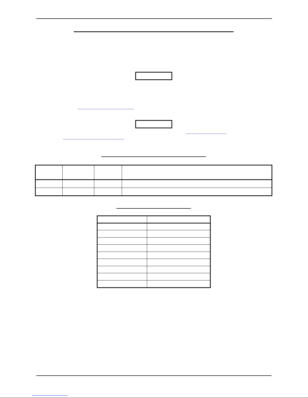
CURRENT REVISION DESCRIPTION
Revision
Page
Number(s)
Section
Number
A All All Initial release
DOCUMENT PAGINATION
Section Page Range
Table of Contents i – vi
Section 1 1-1 – 1-8
Section 2 2-1 – 2-6
Section 3 3-1 – 3-4
Section 4 4-1 – 4-6
Appendix A A-1 – A-2
Appendix B B-1 – B-12
Appendix C C-1 – C-4
Appendix D D-1 – D-2
Description of Change
GTX 23 Installation Manual Page i
190-00906-01 Revision A

TABLE OF CONTENTS
PARAGRAPH PAGE
Section 1 GENERAL DESCRIPTION............................................................. 1-1
Introduction ............................................................................................................................ 1-1
Equipment Description...........................................................................................................1-1
ADS-B Capabilities................................................................................................................ 1-1
ADS-B Versions ........................................................................................................................... 1-2
TIS System Capabilities.........................................................................................................1-2
Mutual Suppression Pulses ....................................................................................................1-2
Interface Summary ................................................................................................................. 1-3
Technical Specifications ........................................................................................................1-4
Physical Characteristics ................................................................................................................ 1-4
General Specifications .................................................................................................................. 1-4
Power Requirements ..................................................................................................................... 1-5
License Requirements ............................................................................................................1-5
Certification............................................................................................................................ 1-5
GTX 23 TSO/ETSO/RTCA/ICAO Compliance........................................................................... 1-6
TSO/ETSO Deviations.................................................................................................................. 1-7
Reference Documents ............................................................................................................1-7
Aviation Limited Warranty .................................................................................................... 1-8
Section 2 INSTALLATION OVERVIEW....................................................... 2-1
Introduction ............................................................................................................................ 2-1
Installation Materials.............................................................................................................. 2-1
Equipment Available .................................................................................................................... 2-1
Additional Equipment Required ...................................................................................................2-1
Installation Considerations.....................................................................................................2-1
Preservation of Previous Systems................................................................................................. 2-1
Antenna Location Considerations.................................................................................................2-2
Cabling and Wiring ................................................................................................................ 2-3
Cable Routing Considerations ...................................................................................................... 2-4
Cooling Air............................................................................................................................. 2-4
GTX 23 Mounting Requirements........................................................................................... 2-4
Section 3 INSTALLATION PROCEDURE .................................................... 3-1
Unpacking Unit ...................................................................................................................... 3-1
Wiring Harness Installation.................................................................................................... 3-1
Electrical Connections ...........................................................................................................3-1
Backshell Assembly ...............................................................................................................3-2
Weight and Balance ...............................................................................................................3-2
Electrical Load Analysis ........................................................................................................3-2
Final Installation..................................................................................................................... 3-3
Post Installation Configuration and Checkout .......................................................................3-3
Configuration ................................................................................................................................ 3-3
Interference Check ........................................................................................................................ 3-3
Page ii GTX 23 Installation Manual
Revision A 190-00906-01

Performance (Ramp) Test............................................................................................................. 3-4
Continued Airworthiness .......................................................................................................3-4
Section 4 SYSTEM INTERCONNECTS......................................................... 4-1
Pin Function List ....................................................................................................................4-1
P2301 ............................................................................................................................................ 4-1
Aircraft Power............................................................................................................................... 4-2
Discrete Functions.................................................................................................................. 4-3
Discrete Outputs............................................................................................................................ 4-3
Discrete Inputs .............................................................................................................................. 4-3
Serial Data Electrical Characteristics..................................................................................... 4-4
RS-232 Input/Output..................................................................................................................... 4-4
ARINC 429 Input/Output ............................................................................................................. 4-4
RS-232 Input/Output, Software Update Connections............................................................ 4-5
Appendix A Construction and Validation of Structures............................... A-1
Static Test Loading .............................................................................................................. A-1
Determining Static Load Capability..................................................................................... A-1
Appendix B Shield Block Installation Instructions ........................................B-1
Shield Block Installation Parts ............................................................................................. B-1
Shield Termination Technique – Method A.1 (Standard).................................................... B-3
Shield Termination Technique - Method A.2 (Daisy Chain)............................................... B-7
Shield Termination – Method B.1 (Quick Term)................................................................. B-7
Shield Termination-Method B.2 (Daisy Chain-Quick Term) .............................................. B-9
Daisy Chain between Methods A and B ............................................................................ B-10
Splicing Signal Wires......................................................................................................... B-10
Appendix C External Interface Drawings (Example Only) .......................... C-1
Appendix D Assembly and Installation Drawings ......................................... D-1
GTX 23 Installation Manual Page iii
190-00906-01 Revision A

LIST OF FIGURES
FIGURE PAGE
Section 1 GENERAL DESCRIPTION............................................................. 1-1
Section 2 INSTALLATION OVERVIEW....................................................... 2-1
Antenna Installation Considerations ...................................................................................... 2-2
GTX 23 Stand-Alone Rack (115-00629-00).......................................................................... 2-5
GTX 23 Stand-Alone Rack, Suggested Mounting Locations ................................................ 2-5
Section 3 INSTALLATION PROCEDURE .................................................... 3-1
Section 4 SYSTEM INTERCONNECTS......................................................... 4-1
J2301 Connector..................................................................................................................... 4-1
GTX 23 Software Update Connections.................................................................................. 4-5
Appendix A Construction and Validation of Structures............................... A-1
Upward static Load Test .......................................................................................................A-2
Forward Static Load Test ...................................................................................................... A-2
Appendix B Shield Block Installation Instructions ........................................B-1
Shield Block Installation (78 pin example)........................................................................... B-2
Method A.1 for Shield Termination...................................................................................... B-3
Insulation/Contact Clearance ................................................................................................ B-5
Method A.2 (Daisy Chain) for Shield Termination .............................................................. B-7
Method B.1 (Quick Term) for Shield Termination............................................................... B-8
Method B.2 (Daisy Chain-Quick Term) for Shield Termination.......................................... B-9
Daisy Chain between Methods A and B ............................................................................. B-10
D-Sub Spliced Signal Wire illustration............................................................................... B-11
Appendix C External Interface Drawings (Example Only).......................... C-1
Core Interconnect Examples ................................................................................................ C-1
ADS-B Interconnect Examples ............................................................................................ C-2
TIS Display Options Example ............................................................................................. C-3
Appendix D Assembly and Installation Drawings......................................... D-1
GTX 23 Remote Rack/Connector Assembly ........................................................................ D-1
GTX 23 Connector/Rack Assembly Drawing....................................................................... D-2
Page iv GTX 23 Installation Manual
Revision A 190-00906-01

LIST OF TABLES
TABLE PAGE
Section 1 GENERAL DESCRIPTION............................................................. 1-1
Section 2 INSTALLATION OVERVIEW....................................................... 2-1
Section 3 INSTALLATION PROCEDURE .................................................... 3-1
Pin Contact Part Numbers...................................................................................................... 3-1
Recommended Crimp Tools ..................................................................................................3-2
Unit Power Loads................................................................................................................... 3-2
Section 4 SYSTEM INTERCONNECTS......................................................... 4-1
Appendix A Construction and Validation of Structures .............................. A-1
Static Test Load..................................................................................................................... A-1
Appendix B Shield Block Installation Instructions ........................................B-1
Parts Supplied for a Shield Block Installation (011-01012-01) ............................................ B-1
Parts not supplied for a Shield Block Installation (Figure B-1)............................................ B-1
Shielded Cable Preparations for Garmin Connectors ........................................................... B-3
Shielded Cable Preparations – (Quick Term) ....................................................................... B-9
Appendix C External Interface Drawings (Example Only).......................... C-1
Appendix D Assembly and Installation Drawings......................................... D-1
GTX 23 Installation Manual Page v
190-00906-01 Revision A

This page intentionally left blank
Page vi GTX 23 Installation Manual
Revision A 190-00906-01

1 GENERAL DESCRIPTION
1.1 Introduction
This manual presents the mechanical and electrical installation requirements for installing the Garmin
GTX 23 Mode S Transponder.
1.2 Equipment Description
The Garmin GTX 23 remote-mounted Mode S Transponder is a radio transmitter and receiver that
operates on radar frequencies. It receives ground radar and TCAS interrogations at 1030 MHz, and it
transmits a coded response of pulses at 1090 MHz. The GTX 23 replies to Mode A, Mode C, and Mode S
interrogations. Mode A replies consist of framing pulses and any one of 4,096 codes, which differ in the
position and number of pulses transmitted. Mode C replies include framing pulses and encoded pressure
altitude. Mode S replies can contain various information such as the Mode A code, Mode C altitude,
ICAO address, and Elementary Surveillance and Enhanced Surveillance data described below.
Features of the GTX 23 include support for ADS-B, TIS-A, mutual suppression, IDENT functionality, SI
codes, elementary surveillance (ELS), and enhanced surveillance (EHS). ADS-B, TIS-A, and mutual
suppression are discussed in following sections. IDENT functionality activates a Special Position
Identification (SPI) pulse for 18 seconds in Mode A replies. This helps the air traffic controller confirm
your position on their radar screen. SI codes, ELS, and EHS better facilitate meeting various requirements
for operation in European airspace. SI codes uniquely identify ground radar with overlapping coverage.
Supporting SI codes enables reduction in ground infrastructure complexity. ICAO Annex 10, Volume IV,
Amendment 77, paragraph 2.1.5.1.7.1 mandated SI code support. Elementary and Enhanced Surveillance
provide additional aircraft parameters to ground radar systems (for ELS, see JAA TGL 13 rev 1 dated
June 01, 2003; for EHS, see AMC 20-13, which supersedes JAA NPA 20-12a). Elementary Surveillance
provides a detailed transponder capability report and aircraft identification data (e.g. Flight ID or radio call
sign). Additionally, TCAS II compatible transponders supporting ELS can provide resolution advisory
data if the aircraft is equipped with TCAS II. (ELS is Mode S BDS registers (1,0), (2,0), and (3,0).)
Enhanced Surveillance provides selected vertical intention, track and turn reporting, and heading and
speed reporting. (EHS is Mode S BDS registers (4,0), (5,0), and (6,0).)
1.3 ADS-B Capabilities
The GTX 23 provides the capabilities of Automatic Dependent Surveillance-Broadcast (ADS-B)
technology, which improves situational awareness and flight safety. With ADS-B capabilities, position,
velocity, and heading information are automatically transmitted to other aircraft and ground stations. The
current air traffic control system depends on a transponder request for pertinent aircraft information.
ADS-B provides automatic transmission of aircraft information without a request.
NOTE
TSOA GPS data from a Garmin GNS 400W/500W-series WAAS enabled unit,
GTN 6XX series, or GTN 7XX series unit is required to support ADS-B
transmissions. If a GNS 400W/500W-series unit is used, note that it must use
main software version 3.20 or later.
GTX 23 Installation Manual Page 1-1
190-00906-01 Revision A

1.3.1 ADS-B Versions
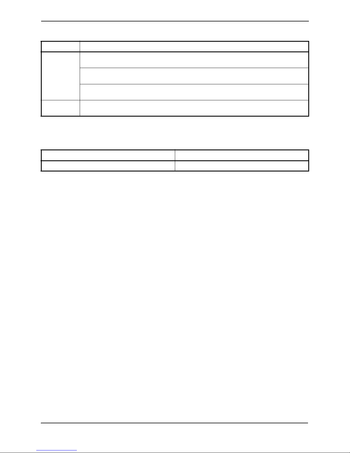
There are three distinct ADS-B versions recognized by regulatory authorities. As shown in the table
below, the Garmin GTX 23 w/ES currently supports ADS-B Out 1090MHz Extended Squitter capability
meeting ‘Version 1’ ADS-B system requirements.
ADS-BVersion GTX 23 w/ES Compliant
Version 0 No Equipment designed to TSO-166 / RTCA DO-260
Version 1 Yes Equipment designed to TSO-166a / RTCA DO-260A
Version 2* No Equipment designed to TSO-166b / RTCA DO-260B
Regulatory Standard/Minimum Performance
Specification
*Version required by 2020 ADS-B mandate defined in 14 CFR 91.225
1.4 TIS System Capabilities
Traffic Information Service (TIS) provides a graphic display of traffic advisory information in the cockpit
for non-TCAS equipped aircraft.
TIS is a ground-based service providing relative location of all transponder equipped aircraft within a
specified service volume. The TIS ground sensor uses real time track reports to generate traffic
notification.
Traffic display is available to aircraft equipped with a Mode S data link such as the Garmin GTX 23
transponder. Traffic can then be displayed on a Garmin GDU Primary Flight Display, or GNS 400W/
500W-series unit.
Surveillance data includes all transponder equipped aircraft within the coverage volume. Aircraft without
an operating transponder are invisible to TIS. TIS displays traffic within seven nautical miles from 3000
feet below to 3500 feet above the requesting aircraft.
1.5 Mutual Suppression Pulses
Other equipment on board the aircraft may transmit in the same frequency band as the transponder. DME,
TCAS, or another transponder are examples of equipment that operate in the same frequency band. Mutual
suppression is a synchronous pulse that is sent to the other equipment to suppress transmission of a
competing transmitter for the duration of the transmission. The transponder transmission is suppressed by
an external source, and other equipment on board that transmit in the same frequency band are suppressed
by the GTX 23 transponder. This feature is designed to limit mutual interference.
Page 1-2 GTX 23 Installation Manual
Revision A 190-00906-01

1.6 Interface Summary
The GTX 23 provides the following interface connections via the rear connector. See Section 4 and
Appendix C for connection details.
• External IDENT input
• External STBY input (useful for dual transponder installations)
• External mutual suppression pulse input/output
• Aircraft power input (14/28 Vdc)
• RS-232 input #1 connection for altitude and unit control data
• RS-232 output #1 connection for TIS and unit status
• RS-232 input #2 connection for GPS data for ADS-B
• Supports Comm-A and Comm-B protocol
• ARINC 429 outputs for TIS data
The GTX 23 supports the following list of Comm-B Definition Subfield (BDS) registers:
• BDS (0,0) Air Initiated Comm-B (AICB)
• BDS (1,0) Data Link Capability Report
• BDS (1,7) Common Usage Ground Initiated Comm-B (GICB) Capability Report
• BDS (1,8) Mode S Specific Services GICB Capability Report
• BDS (1,9) Mode S Specific Services GICB Capability Report
• BDS (1,D) Mode S Specific Services Protocols (MSP) Capability Report
• BDS (2,0) Aircraft Identification
• BDS (4,0) Selected Vertical Intention
• BDS (5,0) Track and Turn Report
• BDS (6,0) Heading and Speed Report
• BDS (0,6) Extended Squitter surface Position
• BDS (0,5) Extended Squitter Airborne Position
• BDS (0,8) Extended Squitter Aircraft Identification and Category
• BDS (0,9) Extended Squitter Airborne Velocity – Subtypes 1 and 3
• BDS (0,A) Extended Squitter Event Driven Data
• BDS (6,1) Emergency/Priority Status
• BDS (6,5) Aircraft operational Status
GTX 23 Installation Manual Page 1-3
190-00906-01 Revision A

1.7 Technical Specifications
1.7.1 Physical Characteristics
Characteristic Specification
Stand-Alone Rack Width 1.78 Inches (45 mm)
Stand-Alone Rack Height 6.92 Inches (176 mm)
Stand-Alone Rack Weight 0.9 lbs. (0.41 kg)
Depth Including Connectors (measured from front face
of unit to rear of connector backshells)
Depth Including Connectors and Shield Blocks (measured from front face of unit to rear of shield blocks)
Connecter Weight (including backshell) 0.4 lbs (0.18 kg)
GTX 23 Unit Weight 3.1 lbs. (1.41 kg)
11.05 Inches (281 mm)
11.44 inches (291 mm)
1.7.2 General Specifications
Characteristic Specification
Regulatory Compliance; GTX 23 w/ES RTCA DO-160D, DO-181C, and EUROCAE/ED-73B
Unit Software RTCA DO-178B Level C
Complex Electronic Hardware RTCA/DO-254 Level C
FCC Authorization Emission Designator 12M0M1D
Temperature Range -45°C to +70°C (continuous operation)
Altitude 55,000 Feet
Transmitter Frequency 1090 MHz ±1 MHz
Transmitter Power 125 Watts minimum, 250 Watts nominal
Receiver Frequency 1030 MHz
Receiver Sensitivity -74 dBm nominal for 90% replies
Mode A Capability 4096 Identification Codes
Mode C Capability
Mode S Capability 4096 Identification Codes, Altitude
External Suppression Input Low ≤ 0.5 V; High ≥ 8 V
External Suppression Output
Audio Output 4.04 Vrms to 7.85 Vrms into a 500 ohm load
Page 1-4 GTX 23 Installation Manual
Revision A 190-00906-01
100 Foot Increments from -1000 to 62,700 feet.
25 Foot Increments from -1000 to 50,175 feet with suitable serial data
altitude.
Output: minimum is +18V (for 300 ohm load) and maximum of +23V
(for 2000 ohm load)

1.7.3 Power Requirements
Characteristic Specification
Input Voltage
Power Input 22 Watts Typical, 45 Watts Maximum
Maximum Full TSO Reply Rate;
Mode C, 1200 PRF, Code 7777
Maximum Quiescent 0.85 A @ 28 Vdc, 1.1A @ 14 Vdc
14/28 Vdc See the Environmental Qualification Form for details on
surge ratings and minimum/maximum operating voltages.
1.6 A @ 28 Vdc, 3.1 A @14 Vdc
1.8 License Requirements
The Telecommunications Act of 1996, effective February 8, 1996, provides the FCC discretion to
eliminate radio station license requirements for aircraft and ships. The GTX 23 installation must comply
with current transmitter licensing requirements. To find out the specific details on whether a particular
installation is exempt from licensing, please visit the FCC web site http://wireless.fcc.gov/aviation.
If an aircraft license is required, make application for a license on FCC form 404, Application for Aircraft
Radio Station License. The FCC also has a fax-on-demand service to provide forms by fax. The GTX 23
owner accepts all responsibility for obtaining the proper licensing before using the GTX 23.
CAUTION
The UHF transmitter in this equipment is guaranteed to meet federal
communications commission acceptance over the operating temperature range.
Modifications not expressly approved by Garmin could invalidate the license and
make it unlawful to operate the equipment.
1.9 Certification
The conditions and tests required for TSO approval of this article are minimum performance standards. It
is the responsibility of those installing this article either on or within a specific type or class of aircraft to
determine that the aircraft installation conditions are within the TSO standards. The article may be
installed only if performed under 14 CFR Part 43 or the applicable airworthiness requirements.
GTX 23 Installation Manual Page 1-5
190-00906-01 Revision A

1.9.1 GTX 23 TSO/ETSO/RTCA/ICAO Compliance
Function
Air Traffic Control Radar
Beacon System/Mode Select
(ATCRBS/MODE S) Airborne
Equipment
Traffic Information Service
(TIS)
Air Traffic Control Radar
Beacon System/Mode Select
(ATCRBS/MODE S) Airborne
Equipment
Extended Squitter Automatic
Dependent Surveillance –
Broadcast (ADS-B) and Traffic
Information Services –
Broadcast (TIS-B)
Extended Squitter Automatic
Dependent Surveillance –
Broadcast (ADS-B) and Traffic
Information Services –
Broadcast (TIS-B)
Enhanced Surveillance
Performance Standard
(TSO/ETSO/RTCA/
Category
EUROCAE)
TSO-C112 Class 2A
RTCA DO-239 -
2C112b
ETSO-2C112b
TSO-C166a (See Note 2)
ETSO-C166a (See Note 2)
ICAO Annex 10, Amendment
77 Tables: 2-64, 2-80, 2-96
(See Note 1)
Class 1
Level 2es
B0 (non-
diversity)
B0 (non-
diversity)
-
Applicable LRU SW Part
Numbers
All 006-B1417-00
RTCA DO-178B Compliance DO-178B Level C
RTCA DO-254 Compliance DO-254 Level C
Note 1: Complies with ICAO Annex 10, Amendment 77 Tables: 2-64, 2-80, 2-96 functionality only when
the Enhanced Surveillance function is enabled during configuration.
Note 2: Complies with TSO-166a/ETSO-166a functionality only when the ADS-B function is enabled
during configuration
Page 1-6 GTX 23 Installation Manual
Revision A 190-00906-01
1.9.2 TSO/ETSO Deviations
TSO/ETSO Deviation
1. Garmin was granted a deviation from TSO-C112 to use RTCA DO-178B instead of RTCA
DO-178A.
TSO-C112
TSO-C166
2. Garmin was granted a deviation from TSO-C112 to use RTCA DO-160D instead of RTCA
DO-160B.
3. Garmin was granted a deviation from TSO-C112 to use RTCA DO-181C instead of RTCA
DO-181.
1. Garmin was granted a deviation from TSO-C166 to use RTCA DO-160D instead of RTCA
DO-160E.
1.10 Reference Documents
The following publications are sources of additional information for installing the GTX 23. Before
installing the unit, the technician should read all relevant referenced materials along with this manual.
Part Number Document
190-01115-01 G3X Installation Manual
GTX 23 Installation Manual Page 1-7
190-00906-01 Revision A

1.11 Aviation Limited Warranty
All Garmin avionics products are warranted to be free from defects in materials or workmanship for: one
years from the date of purchase for new Remote-Mount and Panel-Mount products; one year from the date
of purchase for new portable products and any purchased newly-overhauled products; six months for
newly-overhauled products exchanged through a Garmin Authorized Service Center; and 90 days for
factory repaired or newly-overhauled products exchanged at Garmin in lieu of repair. Within the applicable
period, Garmin will, at its sole option, repair or replace any components that fail in normal use. Such
repairs or replacement will be made at no charge to the customer for parts or labor, provided that the
customer shall be responsible for any transportation cost. This warranty does not apply to: (i) cosmetic
damage, such as scratches, nicks and dents; (ii) consumable parts, such as batteries, unless product damage
has occurred due to a defect in materials or workmanship; (iii) damage caused by accident, abuse, misuse,
water, flood, fire, or other acts of nature or external causes; (iv) damage caused by service performed by
anyone who is not an authorized service provider of Garmin; or (v) damage to a product that has been
modified or altered without the written permission of Garmin. In addition, Garmin reserves the right to
refuse warranty claims against products or services that are obtained and/or used in contravention of the
laws of any country.
THE WARRANTIES AND REMEDIES CONTAINED HEREIN ARE EXCLUSIVE AND IN LIEU OF
ALL OTHER WARRANTIES, WHETHER EXPRESS, IMPLIED OR STATUTORY, INCLUDING ANY
LIABILITY ARISING UNDER ANY WARRANTY OF MERCHANTABILITY OR FITNESS FOR A
PARTICULAR PURPOSE, STATUTORY OR OTHERWISE. THIS WARRANTY GIVES YOU
SPECIFIC LEGAL RIGHTS, WHICH MAY VARY FROM STATE TO STATE.
IN NO EVENT SHALL GARMIN BE LIABLE FOR ANY INCIDENTAL, SPECIAL, INDIRECT OR
CONSEQUENTIAL DAMAGES, WHETHER RESULTING FROM THE USE, MISUSE OR
INABILITY TO USE THE PRODUCT OR FROM DEFECTS IN THE PRODUCT. SOME STATES DO
NOT ALLOW THE EXCLUSION OF INCIDENTAL OR CONSEQUENTIAL DAMAGES, SO THE
ABOVE LIMITATIONS MAY NOT APPLY TO YOU.
Garmin retains the exclusive right to repair or replace (with a new or newly-overhauled replacement
product) the product or software or offer a full refund of the purchase price at its sole discretion. SUCH
REMEDY SHALL BE YOUR SOLE AND EXCLUSIVE REMEDY FOR ANY BREACH OF
WARRANTY.
Online Auction Purchases: Products purchased through online auctions are not eligible for warranty
coverage. Online auction confirmations are not accepted for warranty verification. To obtain warranty
service, an original or copy of the sales receipt from the original retailer is required. Garmin will not
replace missing components from any package purchased through an online auction.
International Purchases: A separate warranty may be provided by international distributors for devices
purchased outside the United States depending on the country. If applicable, this warranty is provided by
the local in-country distributor and this distributor provides local service for your device. Distributor
warranties are only valid in the area of intended distribution. Devices purchased in the United States or
Canada must be returned to the Garmin service center in the United Kingdom, the United States, Canada,
or Taiwan for service.
Garmin International, Inc. Garmin (Europe) Ltd.
1200 East 151st Street Liberty House, Bulls Copse Road
Olathe, Kansas 66062, U.S.A. Hounsdown Business Park
Phone:913/397.8200 Romsey, SO40 9RB, U.K.
FAX:913/397.0836 Phone:44/ (0) 870.8501241
FAX:44/ (0) 870.850125
Page 1-8 GTX 23 Installation Manual
Revision A 190-00906-01
 Loading...