

Page 1

GTS 8XX
Part 23 AML STC Maintenance Manual
with Instructions for Continued Airworthiness
Aircraft Make, Model, Registration Number, and Serial
Number, and accompanying STC configuration
information in Appendix A, must be completed and saved
with aircraft permanent records.
190-01279-01 July 2018 Revision 2
Page 2

© 2014-2018 Garmin International or its subsidiaries
All Rights Reserved
Except as expressly provided herein, no part of this manual may be reproduced, copied, transmitted,
disseminated, downloaded or stored in any storage medium, for any purpose without the express prior
written consent of Garmin. Garmin hereby grants permission to download a single copy of this manual and
of any revision to this manual onto a hard drive or other electronic storage medium to be viewed and to
print one copy of this manual or of any revision hereto, provided that such electronic or printed copy of this
manual or revision must contain the complete text of this copyright notice and provided further that any
unauthorized commercial distribution of this manual or any revision hereto is strictly prohibited.
Garmin
®
, flyGarmin®, and flyGarmin.com
®
are registered trademarks of Garmin International or its
subsidiaries. GDU™, GDL™, GNS™, GTN™, GTS™, and GTX™ are trademarks of Garmin
International or its subsidiaries. These trademarks may not be used without the express permission of
Garmin.
®
Adobe
is a registered trademark of Adobe Systems Incorporated. All rights reserved.
All other product or company names mentioned in this manual are trade names, trademarks, or registered
trademarks of their respective owners.
For aviation product support, visit flyGarmin.com
.
For information regarding the Aviation Limited Warranty
, refer to Garmin’s website.
190-01279-01 GTS 8XX Part 23 AML STC Maintenance Manual
Rev. 2 Page i
Page 3

RECORD OF REVISIONS
Revision Revision Date Description
1 05/01/2014 Initial Release.
2
07/25/2018
Added information pertaining to the GTS 800, 820, and 850.
CURRENT REVISION DESCRIPTION
Section Description of Change
Updated “GTS Processor” to “GTS 800/820/850/825/855.”
1.3.1
1.4 Added GTS 8X0/GPA 65 (GTS 800/GTS 820/GTS 850) Installation (P/N 190-00587-00).
2.3
4.3
5.1 Added “GTS 8X0 Install Tool (P/N 006-A0242-00).”
5.3 Updated “Baro Altitude” fault to “Pressure Altitude” in Table 5-1 GTS 8XX System Faults.
6.1 Added Section 6.1 GTS 8X0.
Updated “GTS Processor LRU” to “GTS 825 or 855 LRU.”
Added “GTS 8X0 refers to the GTS 800, 820, or 850 LRU at the core of the GTS 8XX
system.”
Added GTS 800 and GTS 820/850 requirements to Table 2-1 GTX 8XX System Current
Requirements.
Updated procedure for antenna visual inspection to define inspection criteria.
Updated procedure for antenna visual inspection - suspected lightning strike to include
inspection criteria.
6.2 Added Section 6.2 GPA 65.
7.3 Added content for GTS 8X0 Install Tool (P/N 006-A0242-00).
7.3.1 Added note regarding GTS 8XX install tools.
Appendix A Updated title of Appendix A to “Aircraft Installation Record.”
A.2.1
A.3
Appendix B Updated title of Appendix B to “Electrical Bonding Procedures.”
B.3
B.4 Added bonding strap restriction of six inches.
Added GDU 7XX equipment reference to Table A-1 GTS 8XX System Interfaces to
Garmin Equipment.
Updated aircraft profile to Figure A-2 Equipment Location and Wire Routing - Twin
Engine Airplane.
Added flag notes for Figure B-7.
Added 5:1length-to-width ratio requirement.
Added bonding strap restriction of six inches.
190-01279-01 GTS 8XX Part 23 AML STC Maintenance Manual
Rev. 2 Page ii
Page 4
INFORMATION SUBJECT TO EXPORT CONTROL LAWS
WARNING
CAUTION
NOTE
This document may contain information that is subject to the Export Administration Regulations (EAR)
issued by the United States Department of Commerce (15 CFR, Chapter VII, Subchapter C) and may not
be exported, released, or disclosed to foreign nationals inside or outside of the United States without first
obtaining an export license.
Information in this document is subject to change without notice. For updates and supplemental
information regarding the operation of Garmin products, visit
flyGarmin.com.
DEFINITIONS OF WARNINGS, CAUTIONS, AND NOTES
A Warning means injury or death is possible.
A Caution means that damage to the equipment is possible.
A Note provides additional information.
190-01279-01 GTS 8XX Part 23 AML STC Maintenance Manual
Rev. 2 Page iii
Page 5

TABLE OF CONTENTS
1 INTRODUCTION..............................................................................................................................1-1
1.1 Scope ..........................................................................................................................................1-2
1.2 Organization ...............................................................................................................................1-2
1.3 Definitions and Abbreviations ...................................................................................................1-3
1.4 Related Publications...................................................................................................................1-3
1.5 Distribution.................................................................................................................................1-4
2 GENERAL DESCRIPTION.............................................................................................................2-1
2.1 System Overview .......................................................................................................................2-2
2.2 Equipment Description...............................................................................................................2-2
2.3 Electrical Current Requirements ................................................................................................2-2
2.4 Interface Summary .....................................................................................................................2-3
2.5 Ground Plane..............................................................................................................................2-4
3 CONTROL AND OPERATION.......................................................................................................3-1
4 INSTRUCTIONS FOR CONTINUED AIRWORTHINESS.........................................................4-1
4.1 Airworthiness Limitations..........................................................................................................4-2
4.2 Servicing Information ................................................................................................................4-2
4.3 Maintenance Intervals ................................................................................................................4-3
5 TROUBLESHOOTING ....................................................................................................................5-1
5.1 Troubleshooting Software ..........................................................................................................5-2
5.2 Assert Log Diagnosis .................................................................................................................5-3
5.3 System Faults .............................................................................................................................5-4
6 EQUIPMENT REMOVAL AND RE-INSTALLATION...............................................................6-1
6.1 GTS 8X0 ....................................................................................................................................6-2
6.2 GPA 65.......................................................................................................................................6-2
6.3 GTS Processor............................................................................................................................6-3
6.4 Configuration Module ................................................................................................................6-3
6.5 Antenna Coaxial Cable...............................................................................................................6-4
6.6 Directional Antenna ...................................................................................................................6-6
6.7 Omni-directional (Monopole) Antenna......................................................................................6-7
7 RETURN TO SERVICE ...................................................................................................................7-1
7.1 Maintenance Records .................................................................................................................7-2
7.2 Return to Service Requirements.................................................................................................7-2
7.3 Configuration and Checkout ......................................................................................................7-3
7.4 System Checkout........................................................................................................................7-8
APPENDIX A AIRCRAFT INSTALLATION RECORD...................................................................A-1
A.1 General Installation Information ...............................................................................................A-2
A.2 Interfaced Equipment ................................................................................................................A-3
A.3 Equipment Locations and Wire Routing...................................................................................A-5
A.4 Configuration Log .....................................................................................................................A-8
A.5 Aircraft Wiring Diagrams .........................................................................................................A-9
APPENDIX B ELECTRICAL BONDING PROCEDURES...............................................................B-1
B.1 Considerations for Untreated or Bare Dissimilar Metals .......................................................... B-2
B.2 Preparation of Aluminum Surfaces ...........................................................................................B-3
B.3 Composite Aircraft ....................................................................................................................B-4
B.4 Tube and Fabric Aircraft ........................................................................................................... B-9
190-01279-01 GTS 8XX Part 23 AML STC Maintenance Manual
Rev. 2 Page iv
Page 6

LIST OF FIGURES
Figure 2-1 GTS 8XX System Interface Diagram ..................................................................................2-3
Figure 3-1 GTS 8XX Traffic System Controls ......................................................................................3-1
Figure 5-1 GTS Assert Log Diagnosis Tool ..........................................................................................5-3
Figure 7-1 GTS Processor Install Tool - Normal Tab ...........................................................................7-4
Figure 7-2 GTS Processor Install Tool - Configuration Tab .................................................................7-6
Figure 7-3 GTS Processor Install Tool - Upload Tab ............................................................................7-7
Figure 7-4 GTS Processor Install Tool - Assert Tab .............................................................................7-7
Figure 7-5 GTS Processor Install Tool - Normal Tab ...........................................................................7-9
Figure 7-6 Target Aircraft Position for Traffic Display Flight Check ................................................7-11
Figure A-1 Equipment Location and Wire Routing - Single-Engine Airplane ....................................A-6
Figure A-2 Equipment Location and Wire Routing - Twin Engine Airplane ......................................A-7
Figure A-3 GTS 8XX System Configuration Log ................................................................................A-8
Figure B-1 Electrical Bonding Preparation – Nut Plate .......................................................................B-2
Figure B-2 Electrical Bonding Preparation – Bolt/Nut Joint ................................................................B-2
Figure B-3 Electrical Bond Preparation – Terminal Lug .....................................................................B-2
Figure B-4 Fiberglass Insulation for Carbon Material ......................................................................... B-4
Figure B-5 Aluminum Tape Joint ......................................................................................................... B-6
Figure B-6 Aluminum Tape Ground Termination ................................................................................B-6
Figure B-7 GTS Processor Aluminum Tape Installation ..................................................................... B-7
Figure B-8 Electrical Bonding Using Conductive Clamp .................................................................. B-11
190-01279-01 GTS 8XX Part 23 AML STC Maintenance Manual
Rev. 2 Page v
Page 7

LIST OF TABLES
Table 2-1 GTS 8XX System Current Requirements .............................................................................2-2
Table 2-2 Ground Plane Definitions and Ground Path Resistance Requirements ................................2-4
Table 5-1 GTS 8XX System Faults .......................................................................................................5-4
Table 6-1 Recommended Coaxial Cable Length ...................................................................................6-5
Table 7-1 GTS 8XX System Flag Status ............................................................................................... 7-5
Table 7-2 Data Source Status Icons .......................................................................................................7-6
Table 7-3 Ramp Test Intruder Scenario ...............................................................................................7-10
Table A-1 GTS 8XX System Interfaces to Garmin Equipment ............................................................A-3
Table A-2 GTS 8XX System Interfaces to Other Equipment ...............................................................A-4
Table A-3 GTS 8XX Equipment Locations ..........................................................................................A-5
Table B-1 Composite Airframe Bonding Strap Assembly .................................................................... B-5
Table B-2 Bonding Strap Assembly for Air-craft with Tubular Airframes ........................................ B-10
190-01279-01 GTS 8XX Part 23 AML STC Maintenance Manual
Rev. 2 Page vi
Page 8

1 INTRODUCTION
1.1 Scope................................................................................................................................... 1-2
1.2 Organization........................................................................................................................ 1-2
1.3 Definitions and Abbreviations ............................................................................................ 1-3
1.3.1 Definitions .................................................................................................................................1-3
1.3.2 Abbreviations .............................................................................................................................1-3
1.4 Related Publications ........................................................................................................... 1-3
1.5 Distribution ......................................................................................................................... 1-4
190-01279-01 GTS 8XX Part 23 AML STC Maintenance Manual
Rev. 2 Page 1-1
Page 9

1.1 Scope
This document provides maintenance instructions and Instructions for Continued Airworthiness (ICA) for
the GTS 8XX Traffic System as installed under STC SA02121SE. This document satisfies the requirements
for continued airworthiness as defined by 14 CFR Part 23.1529 and 14 CFR Part 23 Appendix G.
1.2 Organization
The following outline briefly describes the organization of this manual:
Section 2: System Description
This section provides a description of the equipment installed by this STC. An overview of the GTS 8XX
system interface is also provided.
Section 3: Control and Operation
This section provides basic control and operation information in relation to maintenance practices. Basic
GTS configuration and software loading is also described.
Section 4: Instructions for Continued Airworthiness
This section provides instructions to maintain continued airworthiness of the GTS 8XX system and system
airworthiness limitations.
Section 5: Troubleshooting
This section provides troubleshooting information to diagnose and resolve problems with GTS 8XX
system equipment.
Section 6: Equipment Removal and Reinstallation
This section provides instructions for the removal and re-installation of GTS 8XX system equipment.
Section 7: Return to Service
This section specifies return to service procedures to be performed upon completion of maintenance of
GTS 8XX system equipment.
Appendix A: Aircraft Installation Record
This appendix is used to record information for a specific GTS 8XX system installation.
Appendix B: Electrical Bonding Procedures
This appendix provides special bonding procedures for non-metallic aircraft.
190-01279-01 GTS 8XX Part 23 AML STC Maintenance Manual
Rev. 2 Page 1-2
Page 10
1.3 Definitions and Abbreviations
1.3.1 Definitions
“GTS 8XX system” refers to the complete system, including GTS 800/820/850/825/855, antennas, and
associated equipment.
“GTS Processor” refers to the GTS 825 or 855 LRU at the core of the GTS 8XX system.
“GTS 8X0” refers to the GTS 800, 820, or 850 LRU at the core of the GTS 8XX system.
1.3.2 Abbreviations
The following terminology is used within this document:
AML Approved Model List
ADS-B Automatic Dependent Surveillance-Broadcast
CFR Code of Federal Regulations
DME Distance Measuring Equipment
FAA Federal Aviation Administration
HSDB High Speed Data Bus
ICA Instructions for Continued Airworthiness
LRU Line Replaceable Unit
MFD Multi-Function Display
SL Sensitivity Level
STC Supplemental Type Certificate
TA Traffic Advisory
TAS Traffic Advisory System
TCAS Traffic Alert and Collision Avoidance System
TSO Technical Standard Order
In this manual, references to GTS 8XX Part 23 AML STC Installation Manual
abbreviated as the “STC IM.”
1.4 Related Publications
Part Number Document
005-00738-01
005-00738-02
190-00587-00
190-00587-02
190-00587-50
190-00587-51
190-01279-00
700704
700784
Master Drawing List, GTS 8XX Part 23 AML STC
Equipment List, GTS 8XX Part 23 AML STC
GTS 8X0/GPA 65 (GTS 800/GTS 820/GTS 850) Installation Manual
GTS Traffic Systems Pilot’s Guide
GTS Processor (GTS 825/855/8000) Installation Manual
GTS Processor Maintenance Manual
GTS 8XX Part 23 AML STC Installation Manual
L-Band/DME Blade Antenna P/N L10-611-( ) Limitations and Installation Instructions
Dayton-Granger Inc. General Installation Instructions for Antennas
(P/N 190-01279-00) may be
190-01279-01 GTS 8XX Part 23 AML STC Maintenance Manual
Rev. 2 Page 1-3
Page 11

1.5 Distribution
This document contains instructions required to maintain continued airworthiness of the GTS 8XX system.
When this
dealers may
document is revised, every page will be revised to indicate the current revision level. Garmin
obtain the latest revision of this document on the Garmin Dealer Resource Center website.
Owner/operators may obtain the latest revision of this document from
A Garmin Service Bulletin describing the revision to this document will be sent to Garmin dealers if the
revision is determined to be significant.
flyGarmin.com.
190-01279-01 GTS 8XX Part 23 AML STC Maintenance Manual
Rev. 2 Page 1-4
Page 12

2 GENERAL DESCRIPTION
2.1 System Overview................................................................................................................ 2-2
2.2 Equipment Description .......................................................................................................2-2
2.3 Electrical Current Requirements......................................................................................... 2-2
2.4 Interface Summary.............................................................................................................. 2-3
2.5 Ground Plane ...................................................................................................................... 2-4
190-01279-01 GTS 8XX Part 23 AML STC Maintenance Manual
Rev. 2 Page 2-1
Page 13
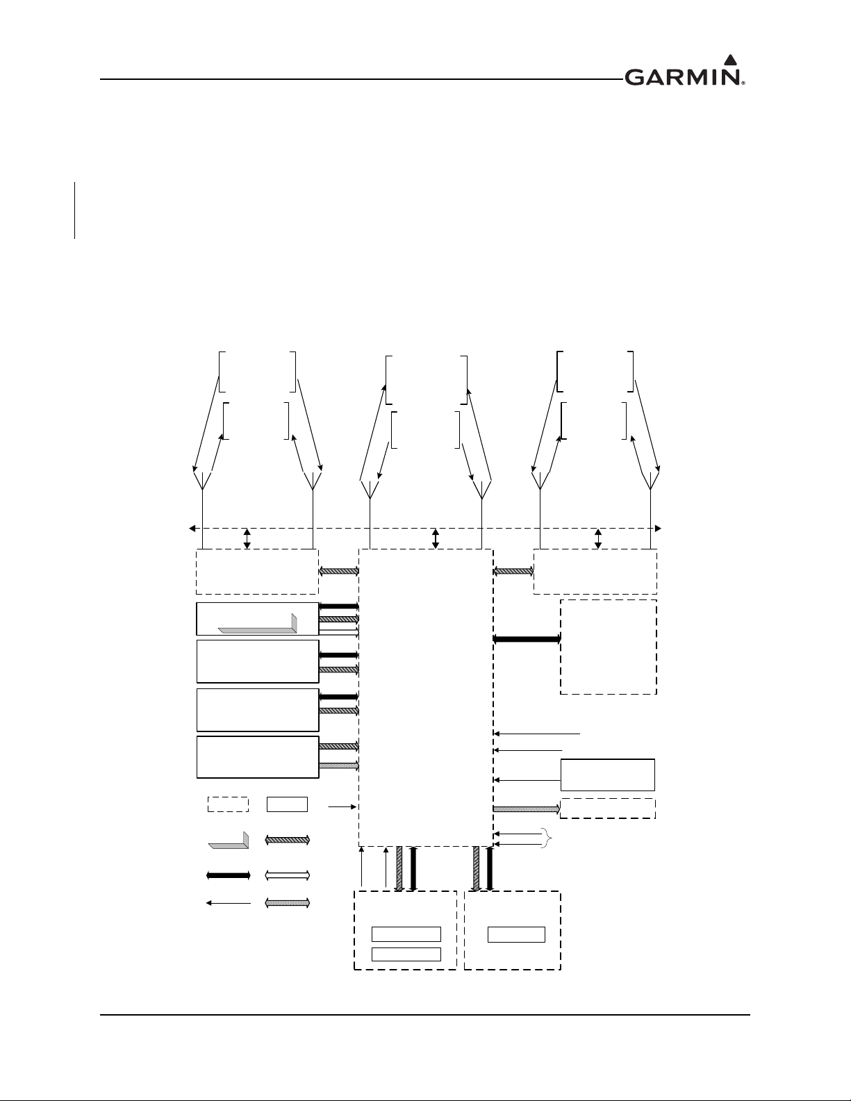
2.1 System Overview
The GTS 8XX system is designed to use active interrogations of Mode S and Mode C transponders to
provide Traffic Advisories (TA) to the pilot. Traffic is displayed on a multifunction display (MFD) via
ARINC 429 and/or High Speed Data Bus (HSDB). An overview of the GTS 8XX system
and its interfaces
are shown in Figure 2-1.
2.2 Equipment Description
The GTS 8XX is a microprocessor-based Line Replaceable Unit (LRU) that uses active interrogations of
Mode S and Mode C transponders to provide Traffic Advisories (TAs) to the pilot.
When properly configured, the GTS 8XX system will utilize passive surveillance to provide ADS-B In
traffic. The GTS ADS-B In capability allows the unit to receive traffic data through its 1090 MHz
Extended Squitter (1090 ES) receiver. Using the received ADS-B Out broadcasts, the system provides
correlated information about target aircraft, including identification, speed, and direction. GPS and
magnetic heading inputs to the GTS 8XX are required for ADS-B In to operate. Although ADS-B In relies
on 1090ES ADS-B Out broadcasts from other aircraft, it is not necessary for the GTS-equipped aircraft to
broadcast an ADS-B Out signal.
Aural alerts are provided to inform the crew of TAs. A top-mounted directional antenna is used to derive
bearing of the intruder aircraft, which is displayed with relative altitude to own aircraft. Top antenna
transmitted interrogations are directional, reducing the number of transponders that receive the
interrogation, thus reducing potential garble on the 1090 MHz band. An optional bottom antenna transmits
omni directional interrogations. A bottom directional antenna installation gives the benefit of intruder
bearing visibi
be degraded on fixed gear aircraft with a bottom directional antenna.
lity for targets that are shaded from the top directional antenna. Target bearing accuracy may
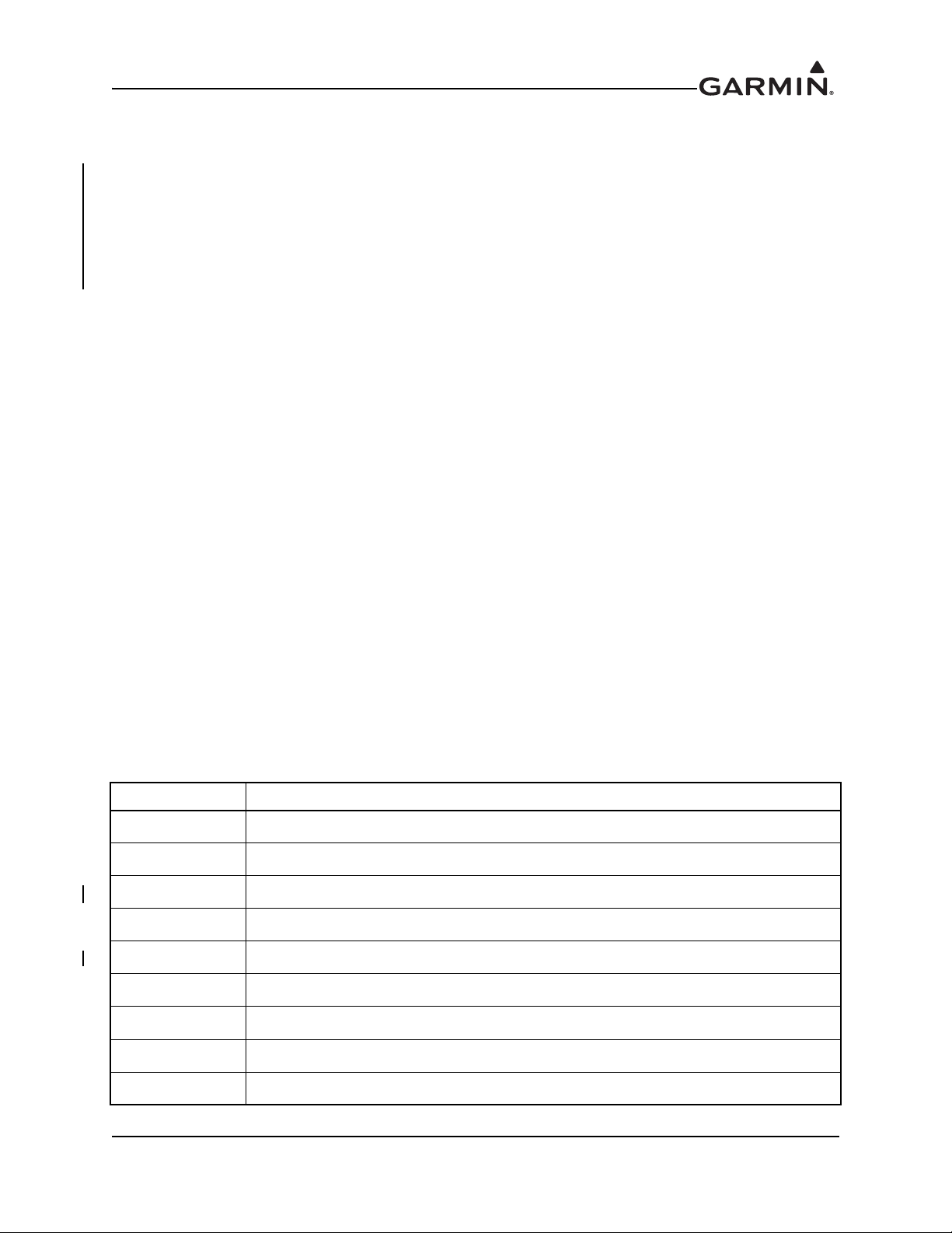
2.3 Electrical Current Requirements
Table 2-1 shows current requirements for the GTS 8XX system.
Table 2-1 GTS 8XX System Current Requirements
LRU
GTS 800 2.2 A 2.6 A 1.1 A 1.5 A
GTS 820/850 2.7 A 3.2 A 1.3 A 1.6 A
GTS Processor 3.5 A 7.5 A 1.7 A
14V Current Draw 28V Current Draw
Typical Maximum Typical Maximum
3.1 A
190-01279-01 GTS 8XX Part 23 AML STC Maintenance Manual
Rev. 2 Page 2-2
Page 14
2.4 Interface Summary
Mode S Transponder
Compatible TX/RX interface
required for power programming
GTS TRAFFIC SYSTEM
Top
Directional
Antenna
Mode C Replies
Mode S Replies
Mode S Squitters
Mode C Interrogations
Broadcast Messages
Mode S Interrogations
1
0
9
0
M
H
z
R
X
1
0
9
0
M
H
zR
X
1
0
3
0
M
H
z
T
X
Optional
Top
Antenna
Bottom
Antenna
Mode A/C/S
Replies
Mode S Squitter
Mode A/C
Interrogations
Mode S Interrogations
Broadcast Messages
1
0
9
0
M
H
zTX
1
0
9
0
M
H
zTX
1
0
3
0
M
H
z
R
X
1
0
3
0
M
H
zR
X
Suppression Bus
Audio Inhibit
Audio Output
Pressure Altitude*
OR
OR
OR
Transponder
Serializer
Magnetic Heading*
(optional)
Radar Altimeter
(optional)
GPS PVT*
(optional)
Data Source
Options
HSDB
Analog I/O
Discrete I/O
RS-232
ARINC 429
LRU Data
OPR/SBY
Self Test
Control/Display*
Unit
Color Display
Knobs/Buttons
Mode S Transponder
(Optional Second Unit)
Compatible TX/RX interface
required for power programming
Optional
Top
Antenna
Bottom
Antenna
Mode A/C/S
Replies
Mode S Squitter
Mode A/C
Interrogations
Mode S Interrogations
Broadcast Messages
1
0
9
0
M
H
zTX
1
0
9
0
M
H
z
T
X
1
0
3
0
M
H
zR
X
1
0
3
0
M
H
z
R
X
Display Unit*
Color Display
Pressure Altitude
Magnetic Heading
GPS PVT
Radio Altitude
Air /Gnd Status
Ldg Gear Position
Mode S TX/RX interface
Control/Display
Ldg Gear Position
Air/Gnd Status
OR
Optional
Bottom
Directional or
Monopole
Antenna
GTS 800 TAS
GTS 820 TAS
GTS 825 TAS
GTS 850 TCAS I
GTS 855 TCAS I
Self Test /
Alt Filter
OPR/SBY
External control inputs required
if Display Unit is only unit installe
d
Audio Panel
High-Priority
Audio Source
(e.g. ,TAWS)
(Optional)
(Req’d for retractable ldg gear)
*The HSDB interface can perform all
of the listed interface functions in
place of separate analog/digital
interfaces.
TRFC Mute
(Optional)
1
0
3
0
M
H
z
T
X
G950/G1000 System*
OR
The GTS 8XX system is designed as an open architecture system that uses ARINC 429, RS-232, and
HSDB communications interfaces, as well as analog and discrete inputs and outputs. GTS 8XX interfaces
include:
• Three RS-232 Inputs/Outputs • Alert Audio Output
• Two RS-422 Input/Output • Ten Active Low Discrete Inputs
• Twelve ARINC 429 Inputs/Outputs • Two Active High Discrete Inputs
• Configuration Module • External Suppression Input/Output
• Aircraft Power Input • Four Annunciator Outputs
• Analog Radar Altimeter Input • HSDB Input/Output
• 26 VAC Heading Reference Input
190-01279-01 GTS 8XX Part 23 AML STC Maintenance Manual
Rev. 2 Page 2-3
Figure 2-1 GTS 8XX System Interface Diagram
Page 15

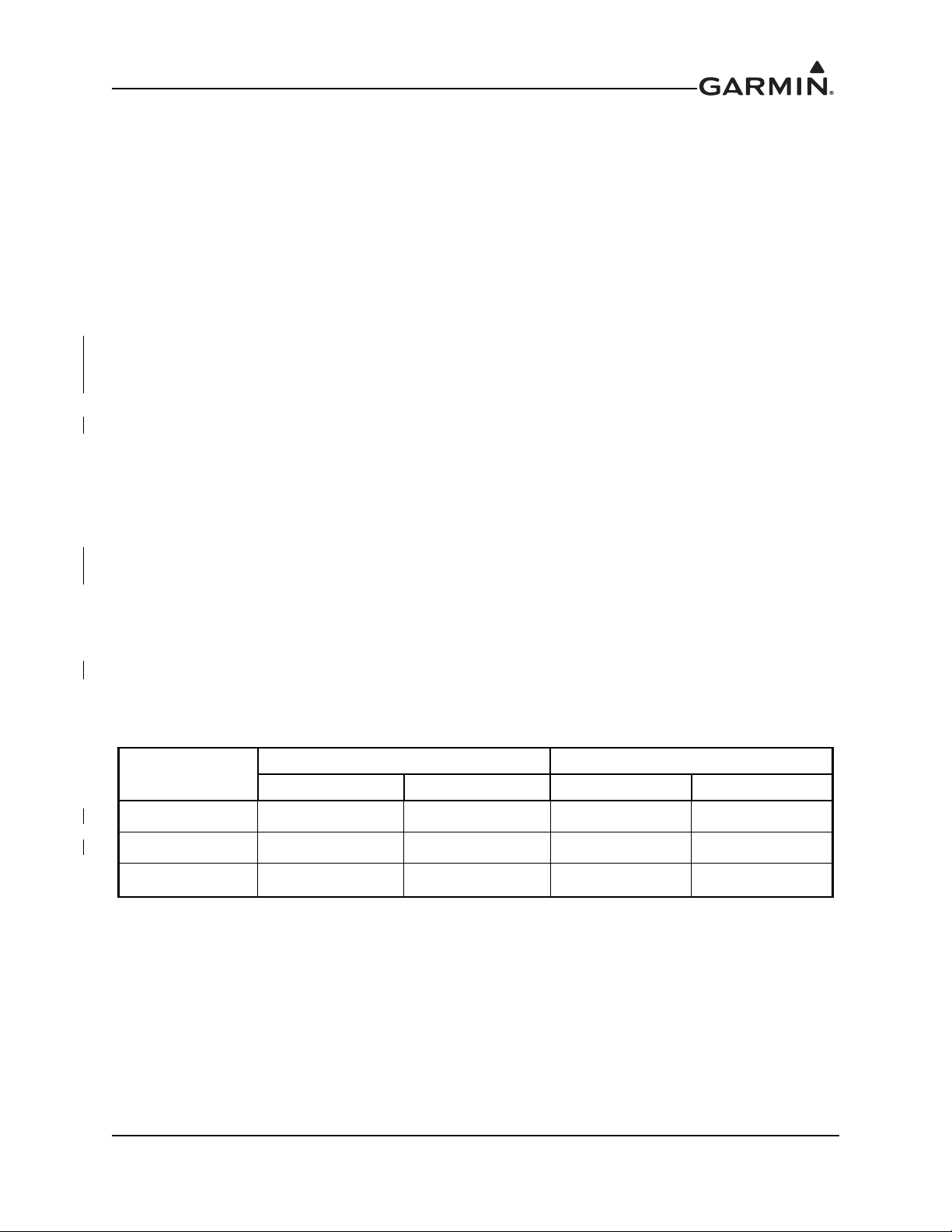
2.5 Ground Plane
Ground plane definition varies with airframe type and aircraft model, as defined in Table 2-2. Refer to the
periodic test and reconditioned resistance values corresponding to these ground plane definitions when
performing the equipment bonding test per Section 4.3. Ensure that all GTS 8XX system antenna coaxial
cables are disconnected during resistance checks.
Table 2-2 Ground Plane Definitions and Ground Path Resistance Requirements
Maximum Resistance Between
Aircraft Type/Model
Ground
Reference
GTS 8XX
Reference (mΩ)
Periodic Test Reconditioned
Chassis and Ground
Notes
Metal airframe
Tube airframe with fabric cover
Composite VFR-only Models
Diamond
Composite IFR Models
Cessna
Cirrus
Diamond
DA 40, DA 40F Instrument panel 50.0 25.0
LC40-550FG,
LC41-550FG,
LC42-550FG
SR20,
SR22,
SR22T
DA 40,
DA 40F
DA 42,
DA 42 N-MG
Nearby metallic
structure
Nearby metallic
structure
Nearby aluminum
lightning
bar/strip
Local grounded
structure
seat support
structure, entry
step)
Nearby structure
lightning
tube
Nearby lightning
ground
ground
(such as
ground
10.0 2.5
10.0 2.5
10.0
10.0
10.0 5.0 [1]
10.0 5.0
5.0
5.0
Notes:
[1] Diamond DA 40 and DA 40F with Diamond OSB 40-004/3 incorporated, or aircraft with
similar factory-installed lightning protection supporting IFR operation.
190-01279-01 GTS 8XX Part 23 AML STC Maintenance Manual
Rev. 2 Page 2-4
Page 16
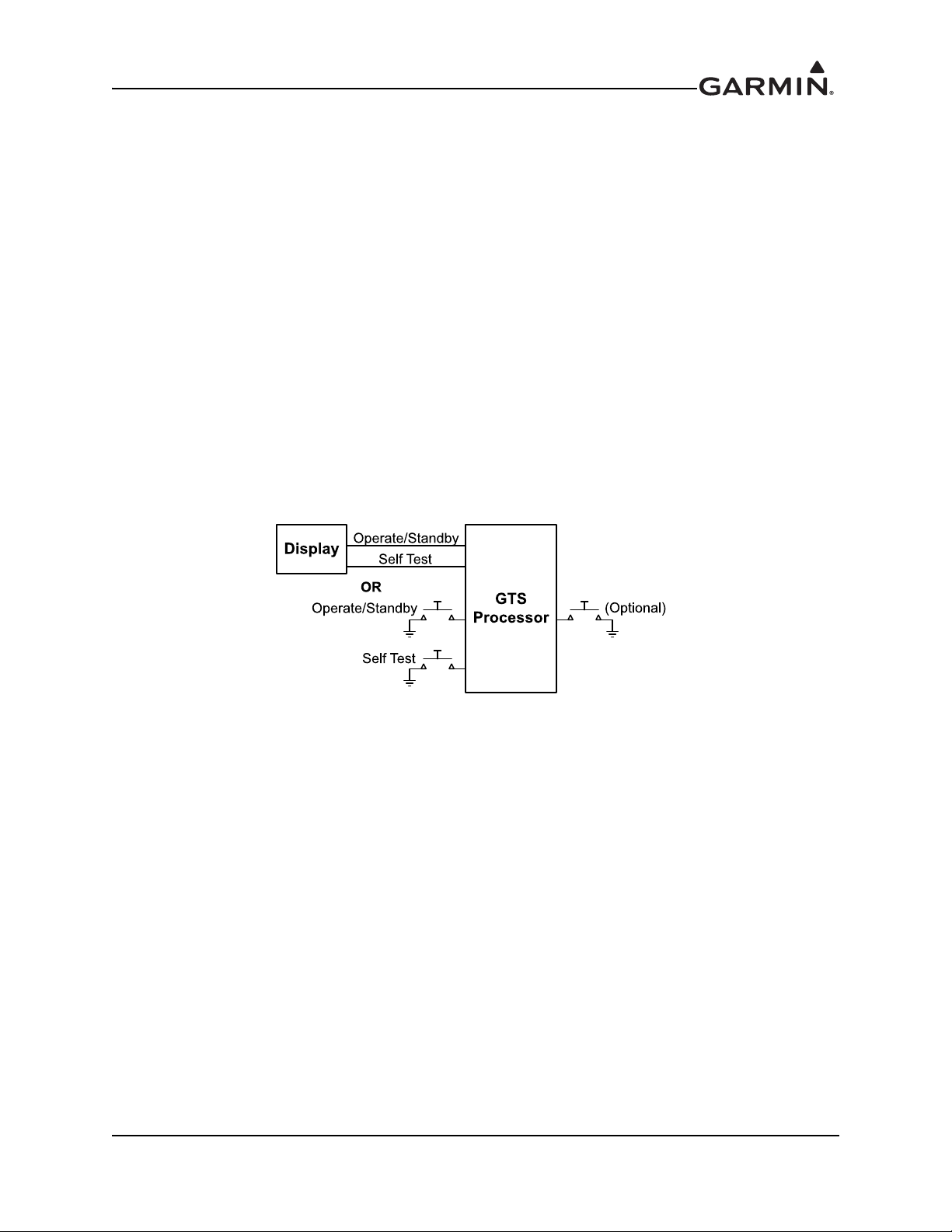
3 CONTROL AND OPERATION
Traffic Mute
The GTS 8XX system includes functions that can be controlled via configured displays or external
switches. Figure 3-1 summarizes GTS 8XX system control. Refer to display documentation for traffic
system control details.
Operate/Standby
The Operate/Standby function toggles the GTS 8XX system between Operate and Standby modes.
Operate/Standby may be controlled through a compatible display or external switch.
Self-Test
The GTS 8XX built-in self-test function may be controlled either through a compatible display or an
external switch.
Traffic Mute (optional)
The optional Traffic Mute function mutes traffic audio alerts and is controlled by an external switch.
Figure 3-1 GTS 8XX Traffic System Controls
190-01279-01 GTS 8XX Part 23 AML STC Maintenance Manual
Rev. 2 Page 3-1
Page 17

4 INSTRUCTIONS FOR CONTINUED AIRWORTHINESS
4.1 Airworthiness Limitations .................................................................................................. 4-2
4.2 Servicing Information ......................................................................................................... 4-2
4.2.1 Periodic Maintenance ................................................................................................................. 4-2
4.2.2 Special Tools ..............................................................................................................................4-2
4.3 Maintenance Intervals......................................................................................................... 4-3
This document is designed for use by the installing agency of the Garmin GTS 8XX Traffic System as
Instructions for Continued Airworthiness in response to 14 CFR 23.1529 and 14 CFR 23 Appendix G. This
ICA includes information required by the operator to adequately maintain the GTS 8XX system installed
under the Approved Model List (AML) STC.
190-01279-01 GTS 8XX Part 23 AML STC Maintenance Manual
Rev. 2 Page 4-1
Page 18
Page 19

4.3 Maintenance Intervals
Maintenance Item Interval Description/Procedure
Antenna visual inspection 12 calendar months
Visually inspect the GTS 8XX system antenna(s) for the following:
• Environmental seal damage or decomposition
• Cracks in the antenna body
• Mounting structure damage or deformation
• Corrosion on metallic structures
If the antenna is not properly attached, or the antenna seal shows signs of damage or deterioration,
the following procedure:
1. Remove, clean, and reattach the antenna.
2. Complete the antenna electrical bonding test as described below.
3. Reseal the antenna.
If the antenna is damaged or cracked, remove and replace the antenna in accordance with Section 6
(antenna(s) installed under this STC), or the antenna installation data (antenna(s) not installed under this
STC). After installing antenna, complete the antenna electrical bonding test described below (if applicable).
If aircraft structure, at location of the antenna, is deformed or damaged, remove the antenna and repair
aircraft structure in accordance with aircraft model-specific structural repair manual. After the aircraft repair
is complete, perform the following:
1. Clean and reattach the antenna.
2. Complete the antenna electrical bonding test as described below (if applicable).
3. Reseal the antenna.
complete
Antenna visual inspection suspected lightning strike
Suspected or actual
lightning strike
In the event of a suspected or actual lightning strike to the aircraft, the GTS 8XX system antenna(s) and
antenna cable installation must be inspected.
1. Inspect the antenna(s) and surrounding area for structural damage.
a. If the antenna is damaged, replace the antenna in accordance with Section 6.
b. If the aircraft structure supporting the antenna installation is deformed or damaged,
2. Inspect the antenna and coaxial cable connector ends for damage. If any damage is found on any
3. Ensure that the coaxial cable connectors are securely attached to the antenna connectors.
4. Perform the GTS 8XX system checkout procedure in accordance with Section 5.
remove the antenna and repair in accordance with procedures detailed in the aircraft
model-specific structural repair manual. When repair is complete, continue with the
following steps.
antenna or coaxial cable connector, replace the antenna(s) or coaxial cable(s) in accordance with
Section 6.
190-01279-01 GTS 8XX Part 23 AML STC Maintenance Manual
Rev. 2 Page 4-3
Page 20

Maintenance Item Interval Description/Procedure
An electrical bonding test must be performed on all GTS 8XX system antennas. The test procedure is:
Antenna electrical bonding test
(Not applicable to
VFR-only
Equipment electrical bonding
test
models)
composite
Every 2000 flight
hours
or ten years,
whichever
Following removal
and
the
rack or bonding
components
AND
Every 2000 flight
hours
whichever
is first
replacement of
GTS 8XX install
or ten years,
is first
1. Gain access to the antenna.
2. Disconnect the coaxial cable connector(s) from the antenna.
3. Measure the resistance between the antenna coaxial connector body and a nearby exposed portion
of aircraft metallic structure (e.g., exposed rivet on fuselage stringer).
4. Verify the resistance is less than or equal to 10 mΩ.
5. Reconnect the antenna connector(s).
In the event of bonding test failure, perform the following procedure:
1. Remove the antenna, clean, and re-install in accordance with Section 6.
2. Measure the resistance between the antenna coaxial connector body and a nearby exposed portion
of aircraft structure (e.g., exposed rivet on fuselage stringer).
3. Verify the resistance is less than or equal to 2.5 mΩ.
1. Disconnect the coaxial cable connector(s) from the GTS 8XX.
2. Disconnect P8001, P8002, and P8003 connectors from the GTS 8XX.
3. Measure the DC resistance between the GTS 8XX chassis and the aircraft ground, as defined in
Table 2-2. Verify the resistance is less than or equal to the appropriate periodic test resistance value
listed in Table 2-2.
In the event of bonding test failure, perform the following procedure:
1. Remove GTS 8XX and install rack from the aircraft per instructions in Section 6.
2. Ensure that the GTS 8XX and install rack are clean and free of dirt and debris.
3. Ensure that all ground path components are in good condition and properly connected and attached
to the aircraft.
4. Re-install the GTS 8XX and install rack in accordance with Section 6.
5. Measure the resistance between the GTS 8XX chassis and the aircraft ground,
as defined in Table 2-2.
6. Verify the resistance is less than or equal to the appropriate reconditioned resistance value listed in
Table 2-2.
Equipment removal and
replacement
On condition
Remove and replace the GTS 8XX and/or GTS 8XX system antenna.
See Section 6 for equipment removal and re-installation instructions.
190-01279-01 GTS 8XX Part 23 AML STC Maintenance Manual
Rev. 2 Page 4-4
Page 21
Maintenance Item Interval Description/Procedure
In the event of a suspected or actual lightning strike to the aircraft, the bonding components for the
Equipment bonding visual
inspection – suspected
lightning strike
Suspected or
actual lightning
strike
GTS 8XX: bonding straps and associated hardware (if applicable) must be inspected. If any damage is
found, the damaged components must be replaced in accordance with specifications and procedures
shown in Appendix B. If any bonding components are replaced, complete the equipment electrical
bonding test as described above.
Equipment visual inspection
12 calendar months
Conduct a visual inspection of the GTS 8XX installation in accordance with 14 CFR 43
Preventative Maintenance, Rebuilding and Alteration, Appendix D. If the equipment fails the visual
inspection, complete the following procedure:
1. Correct improper installations and ensure that all mounting racks and fasteners are secure.
2. Correct improper wire routing and ensure that the wire harness is securely mounted. Replace the
install rack or any wiring, bonding, or shielding component with obvious defects.
3. If the install rack or any bonding components are replaced, complete the equipment electrical
bonding test as described above.
Maintenance,
190-01279-01 GTS 8XX Part 23 AML STC Maintenance Manual
Rev. 2 Page 4-5
Page 22

5 TROUBLESHOOTING
5.1 Troubleshooting Software................................................................................................... 5-2
5.1.1 GTS Install Tool.........................................................................................................................5-2
5.1.2 GTS Assert Log Diagnosis Tool ................................................................................................5-2
5.2 Assert Log Diagnosis.......................................................................................................... 5-3
5.3 System Faults...................................................................................................................... 5-4
This section provides information to assist troubleshooting if problems occur after completing the
maintenance. Refer to the GTS 8XX System Configuration Log, retained in the aircraft permanent records,
for a list of the interfaced equipment and system configuration data. When troubleshooting the GTS 8XX
system, refer to wire routing drawings and interconnect diagrams retained with the aircraft’s permanent
records.
Before troubleshooting the GTS 8XX system, use the GTS Install Tool’s Configuration tab to ensure that
system configuration settings match those recorded in the completed GTS 8XX System Configuration Log
that is retained in the aircraft’s permanent records. See Appendix A for system configuration information.
GTS 8XX system troubleshooting is performed using the following tools:
• Assert Diagnosis
• System Faults
190-01279-01 GTS 8XX Part 23 AML STC Maintenance Manual
Rev. 2 Page 5-1
Page 23

5.1 Troubleshooting Software
The GTS Processor Install Tool (P/N 006-A0242-10) and GTS 8X0 Install Tool (P/N 006-A0242-00)
display GTS 8X5 and GTS 8X0 system faults and generate assert logs. Assert logs can be analyzed using
the GTS Assert Log Diagnosis Tool (P/N 006-A0244-00).
5.1.1 GTS Install Tool
Complete the following procedure to install the GTS Install Tool.
From the Garmin
(P/N 006-A0242-10) for the GTS 825/855 or the GTS 8X0 Install Tool (P/N 006-A0242-00) for the
GTS 800/820/850.
1. Double-click the 32-bit or 64-bit .msi file (depending on PC operating system) to begin
installation.
2. Follow installer prompts and allow driver installation if prompted.
3. Click Close to exit the installer. The GTS Install Tool is now ready to use.
5.1.2 GTS Assert Log Diagnosis Tool
1. Complete the following procedure to install the GTS Assert Log Diagnosis Tool.
2. Download the GTS Assert Log Diagnosis Tool (P/N 006-A0244-00) from the
Garmin
3. Double-click the .msi file to begin installation and follow installer prompts.
4. Click Close to exit the installer. The GTS Assert Log Diagnosis Tool is now ready to use.
Dealer Resource Center, download either the GTS Processor Install Tool
Dealer Resource Center.
190-01279-01 GTS 8XX Part 23 AML STC Maintenance Manual
Rev. 2 Page 5-2
Page 24

5.2 Assert Log Diagnosis
The GTS Assert Log Diagnosis Tool, shown in Figure 5-1, is used with the GTS assert log to assist in the
diagnosis and resolution of asserts generated from the GTS Processor Install Tool or GTS 8X0 Install Tool.
This tool allows for
Windows XP or later and
the Garmin
Diagnosis Tool. See Section 7.3.1.4 for assert log generation instructions.
Dealer Resource Center. A detailed user guide is found under the Help menu of the Assert
troubleshooting the GTS Assert Log using a computer (installed with Microsoft
Microsoft, NET Framework 2.0 SP2 or later) and is available for download from
Figure 5-1 GTS Assert Log Diagnosis Tool
190-01279-01 GTS 8XX Part 23 AML STC Maintenance Manual
Rev. 2 Page 5-3
Page 25

5.3 System Faults
NOTE
GTS 8XX system faults will annunciate on interfaced compatible displays, such as the GDU 620 and on the GTS Install Tool’s Normal tab. Fault descriptions and
corrective actions are listed in Table 5-1.
If any system fault persists after performing the associated troubleshooting actions, return the GTS 8XX to Garmin for service.
Table 5-1 GTS 8XX System Faults
Fault Description Corrective Action
Calibration Data
Configuration Data
FPGA
ROM
Execution CPU execution fault has occurred.
Electrical
Whisper Shout Transmit power is out of tolerance.
Transmit Power
Stored factory calibration parameters are
invalid.
Stored system configuration parameters
are
invalid or Mode S address is invalid (all
zeros
configuration is
FPGA image check failed. Fault will
persist
Internal non-volatile memory failure or
invalid
One or more internal electrical voltages
are
power is
One or more internal transmitter power
source
will persist
or F’s). Fault will persist until
corrected.
until valid FPGA image is loaded.
data image detected.
out of range. Fault will persist until
cycled.
voltages are out of range. Fault
until power is cycled.
Return unit to Garmin for service.
Analyze the assert log. See Section 5.2.
1. Load a valid FPGA image. See Section 7.3.1.3.
2. If an audio or Magnetic Variation image was recently uploaded, retry the upload.
1. Cycle GTS 8XX power. Run self-test. Ensure that self-test occurs in an area free of
buildings and large structures that might reflect signals. [1]
2. Analyze the assert log. See Section 5.2.
1. Cycle GTS 8XX power. Run self-test. [1]
2. Check aircraft power supply.
3. Analyze the assert log. See Section 5.2.
1. Check cable loss configuration.
2. Check antenna installation and all cable connections.
3. Analyze the assert log. See Section 5.2.
1. Cycle GTS 8XX power and run self-test. [1]
2. Check aircraft power supply.
3. Analyze the assert log. See Section 5.2.
1030 MHz
Transmit frequency synthesizer is not
locked.
1. Cycle GTS 8XX power and run self-test. [1]
2. Analyze the assert log. See Section 5.2.
190-01279-01 GTS 8XX Part 23 AML STC Maintenance Manual
Rev. 2 Page 5-4
Page 26

Fault Description Corrective Action
1090 MHz
Receiver Cal GTS 8XX receiver is out of calibration.
Transmitter Cal GTS 8XX transmitter is out of calibration.
Receive frequency synthesizer is not
locked.
1. Cycle GTS 8XX power and run self-test. [1]
2. Analyze the assert log. See Section 5.2.
1. Check antenna installation and all cable connections and run self-test. Ensure that self-test
occurs in an area free of buildings and large structures that might reflect signals. See
Section 7.3.1.3. Receiver self-calibration and test is performed prior to transmitter calibration
and test. In the event that a receiver calibration fault occurs, transmitter self-calibration and
testing will not be performed.
2. Analyze the assert log. See Section 5.2.
Pressure Altitude
Temperature
TCAS Equipage
Radio Altitude
Notes:
[1] If self-test is controlled through a compatible display, refer to display documentation for self-test procedures.
Ownship barometric altitude calculation
is
invalid or has timed out.
Main board or RF receiver temperature is
higher than 100° Celsius or lower than
-60° Celsius. Fault will persist until
internal
acceptable range.
GTS 8XX is not receiving TCAS
Equipage data.
GTS 8XX is not receiving radar altimeter
data.
temperature returns to
Check wiring to the barometric altitude source and ensure that the source is operating. The fault will
clear as soon as valid barometric altitude data is received.
1. Ensure that the GTS 8XX has adequate ventilation and the fan is not obstructed.
2. Analyze the assert log. See Section 5.2.
1. Ensure that transponder is operating properly.
2. Check GTS 8XX wiring to the transponder. This fault will clear as soon as valid TCAS
source data is received.
1. Ensure that radar altimeter is operating properly.
2. Check GTS 8XX wiring to radar altimeter. This fault will clear as soon as valid radio altitude
data is received.
190-01279-01 GTS 8XX Part 23 AML STC Maintenance Manual
Rev. 2 Page 5-5
Page 27

6 EQUIPMENT REMOVAL AND RE-INSTALLATION
WARNING
6.1 GTS 8X0 ............................................................................................................................. 6-2
6.2 GPA 65 ............................................................................................................................... 6-2
6.3 GTS Processor .................................................................................................................... 6-3
6.4 Configuration Module......................................................................................................... 6-3
6.5 Antenna Coaxial Cable .......................................................................................................6-4
6.6 Directional Antenna............................................................................................................ 6-6
6.7 Omni-directional (Monopole) Antenna .............................................................................. 6-7
This section contains procedures and requirements for removal and re-installation of GTS 8XX equipment.
After removal and re-installation, the GTS 8XX system must be checked in accordance with Section 7.
Prior to removal or re-installation of any component of the GTS 8XX system, always ensure
that the aircraft power is off. Unplug any auxiliary power supply.
190-01279-01 GTS 8XX Part 23 AML STC Maintenance Manual
Rev. 2 Page 6-1
Page 28

6.1 GTS 8X0
Removal
1. Ensure there is no power supplied to the GTS 8X0.
2. Gain access to the GTS 8X0. See Appendix A for equipment locations.
3. Disconnect the D-sub and QMA antenna coaxial cable connectors from the GTS 8X0.
4. Loosen the mounting screw on the front of the GTS 8X0 LRU mounting tray.
5. Remove the GTS 8X0 from the install rack.
Re-installation
1. Ensure there is no power supplied to the GTS 8X0.
2. Place the GTS 8X0 in the install rack.
3. Tighten the mounting screw on the front of the GTS 8X0 LRU mounting tray.
4. Connect the D-sub and QMA antenna coaxial cable connectors to the GTS 8X0.
5. Complete the appropriate return to service procedures in Section 7.
6.2 GPA 65
Removal
1. Ensure there is no power supplied to the GPA 65.
2. Gain access to the GPA 65. See Appendix A for equipment locations.
3. Disconnect the QMA antenna coaxial cable connectors from the GPA 65.
4. Disconnect the pigtail connector.
5. Remove the four mounting screws on the GPA 65.
6. Retain the screws for re-installation.
7. Remove the GPA 65.
Re-installation
1. Ensure there is no power supplied to the GPA 65.
2. Install the GPA 65.
3. Attach the GPA 65 with the four mounting screws.
4. Connect the pigtail connector.
5. Connect the antenna connectors on the GPA 65 ensuring each QMA connector is secured.
190-01279-01 GTS 8XX Part 23 AML STC Maintenance Manual
Rev. 2 Page 6-2
Page 29

6.3 GTS Processor
CAUTION
Removal
1. Ensure there is no power supplied to the GTS 8XX.
2. Gain access to the GTS 8XX. See Appendix A for equipment locations.
3. Disconnect the D-sub and antenna coaxial cable connectors from the GTS 8XX.
4. Unscrew the lockdown knob(s).
5. Remove the GTS 8XX from the install rack.
Re-installation
1. Ensure there is no power supplied to the GTS 8XX.
2. Place the GTS 8XX in the install rack with its connectors facing the same side of the rack as
lockdown knob(s).
3. Screw the rack lockdown knob(s) onto the unit lockdown hook(s). Tighten until ratchet clicking
stops.
4. Connect the D-sub and antenna coaxial cable connectors to the GTS 8XX.
5. Complete the appropriate return to service procedures in Section 7.
6.4 Configuration Module
Removal
1. Ensure there is no power supplied to the GTS 8XX.
2. Gain access to the GTS 8XX. See the completed copy of Appendix A retained with the
permanent record for equipment locations.
3. Disconnect D-sub connector P8001 from the GTS 8XX.
4. Remove the two 4-40 x 0.187” countersunk screws from the backshell cover.
5. Remove the three 4-40 x 0.375” pan head screws from the strain relief clamp and remove the clamp.
6. Remove the single screw securing the configuration module.
7. Disconnect the configuration module harness and remove the configuration module.
aircraft
the
Re-installation
190-01279-01 GTS 8XX Part 23 AML STC Maintenance Manual
Rev. 2 Page 6-3
1. Ensure there is no power supplied to the GTS 8XX.
2. Reverse steps 2-7 of the removal procedure above.
Be sure to install the strain relief clamp with its flanges facing AWAY from the wiring
harness. Failure to do so may cause damage to the wiring harness.
3. Complete the appropriate return to service procedures in Section 7.
Page 30

6.5 Antenna Coaxial Cable
NOTE
The GTS 8XX system has stringent coaxial cable requirements. Any damaged or malfunctioning section of
antenna coaxial cable must be replaced. The replacement must include the entire cable length from
connector to connector. See Table 6-1.
To avoid attenuation issues, replace coaxial cables with identical part numbers.
Removal
1. Ensure there is no power supplied to the GTS 8XX.
2. Gain access to the antenna coaxial cable section being removed.
3. Disconnect the QMA or TNC connector at both ends of the coaxial cable section being removed.
4. Remove the coaxial cable section.
Re-installation
1. Ensure there is no power supplied to the GTS 8XX.
2. Route and secure the coaxial cable section.
3. Connect the QMA or TNC connectors at both ends of the coaxial cable section.
4. Complete the appropriate return to service procedures in Section 7.
190-01279-01 GTS 8XX Part 23 AML STC Maintenance Manual
Rev. 2 Page 6-4
Page 31

Coaxial Cable Assembly Repair and Replacement
An individual coaxial cable may be repaired with a maximum reduction in length of two inches from the
length specified in Table 6-1.
Table 6-1 Recommended Coaxial Cable Length
Cable Type
M17/128RG400
PIC 83204 16.7
M17/60-RG142 15.5
PIC S44191 12.2
Carlisle 311901 12.16
PIC S44193 11.8
Carlisle 311601 8.7
PIC S67163 7.5
Carlisle 311501 7.12
Cable Loss
(dB/100ft)
17.2
Connector
Type(s)
Unit/Antenna
TNC/TNC 0.08/0.08 1.98 7.79 10.70 13.60 16.51
TNC/QMA 0.08/0.035 2.24 8.05 10.96 13.87 16.77
TNC/TNC 0.08/0.08 2.04 8.02 11.02 14.01 17.01
TNC/QMA 0.08/0.035 2.31 8.29 11.29 14.28 17.28
TNC/TNC 0.08/0.08 2.19 8.65 11.87 15.10 18.32
TNC/QMA 0.08/0.035 2.48 8.94 12.16 15.39 18.61
TNC/TNC 0.08/0.08 2.79 10.98 15.08 19.18 23.28
TNC/QMA 0.08/0.035 3.16 11.35 15.45 19.55 23.65
TNC/TNC 0.08/0.08 2.80 11.02 15.13 19.24 23.36
TNC/QMA 0.08/0.035 3.17 11.39 15.50 19.61 23.73
TNC/TNC 0.08/0.08 2.88 11.36 15.59 19.83 24.07
TNC/QMA 0.08/0.035 3.26 11.74 15.97 20.21 24.45
TNC/TNC 0.08/0.08 3.91 15.40 21.15 26.90 32.64
TNC/QMA 0.08/0.035 4.43 15.92 21.67 27.41 33.16
TNC/TNC 0.08/0.08 4.53 17.87 24.53 31.20 37.87
TNC/QMA 0.08/0.035 5.13 18.47 25.13 31.80 38.47
TNC/TNC 0.08/0.08 4.78 18.82 25.84 32.87 39.89
TNC/QMA 0.08/0.035 5.41 19.45 26.47 33.50 40.52
Connector
Loss
(dB)
Length
(ft) for
0.5 dB
Length
(ft) for
1.5 dB
Length
(ft) for
2.0 dB
Length
(ft) for
2.5 dB
Length
(ft) for
3.0 dB
Notes:
[1] Actual cable lengths may vary depending on manufacturer’s cable attenuation and
connector specifications.
[2] The values listed include the maximum attenuation of both the maximum length of coaxial
cable and two RF coaxial connectors at a frequency of 1090 MHz.
[3] Vendor: Carlisle Interconnect Technologies
100 Tensolite Drive
St. Augustine, FL 32092
Telephone: 800.458.9960
Fax: 904.829.3447 Website: www.carlisleit.com
[4] Vendor: PIC Wire and Cable
N53 W24747 S Corporate Circle
Sussex, WI 53089-0330
Telephone 800.742.3191 or 262.246.0500
Fax: 262.246.0450 Website: www.picwire.com
[5] See current issue of Qualified Products List, QPL-17.
190-01279-01 GTS 8XX Part 23 AML STC Maintenance Manual
Rev. 2 Page 6-5
Page 32

6.6 Directional Antenna
NOTE
CAUTION
Removal
1. Ensure there is no power supplied to the GTS 8XX.
2. Remove sealant from the antenna’s fasteners.
3. Remove the fasteners attaching the antenna to the fuselage.
4. Remove environmental seal between the antenna and fuselage skin and pull the antenna away from
the fuselage.
5. Disconnect the antenna coaxial cables from the antenna connectors.
6. Remove the antenna from the aircraft. Retain the antenna backing plate (if used) and O-ring.
Re-installation
Ensure the electrical bond meets requirements in Table 2-2.
1. Ensure there is no power supplied to the GTS 8XX.
2. Inspect the antenna O-ring for damage. If necessary, replace the O-ring with a new O-ring.
Otherwise, re-install the O-ring in the groove on the antenna baseplate.
3. Position the antenna backing plate (if used) on the aircraft structure.
4. Reconnect the antenna coaxial cables to the corresponding antenna connectors.
5. Position the antenna on the fuselage and re-install antenna fasteners. Torque 0.164-32 fasteners
10-12 in-lbf.
6. Seal the antenna base to fuselage skin by applying MIL-S-8802 sealant around entire perimeter of
antenna base in a uniform fillet.
7. Ensure that the antenna connector is not contaminated with sealant.
8. Seal the mounting screws with sealant.
Do not use construction grade RTV sealant or sealants containing acetic acid. These
sealants may damage the electrical connections to the antenna. Use of these sealant types
may void the antenna warranty.
9. Complete the appropriate return to service procedures in Section 7.
190-01279-01 GTS 8XX Part 23 AML STC Maintenance Manual
Rev. 2 Page 6-6
Page 33

6.7 Omni-directional (Monopole) Antenna
NOTE
CAUTION
Removal
1. Ensure there is no power supplied to the GTS 8XX.
2. Remove sealant from the antenna’s fasteners.
3. Remove the fasteners attaching the antenna to the fuselage.
4. Remove environmental seal between the antenna and fuselage skin and pull the antenna away from
the fuselage.
5. Disconnect the antenna coaxial cable from the antenna connector.
6. Remove the antenna from the aircraft. Retain the antenna backing plate (if used) and O-ring.
Re-installation
Ensure the electrical bond meets requirements in Table 2-2.
1. Ensure there is no power supplied to the GTS 8XX.
2. Inspect the antenna O-ring for damage. If necessary, replace the O-ring with a new O-ring.
Otherwise, re-install the O-ring in the groove on the antenna baseplate.
3. Position the antenna backing plate (if used) on the aircraft structure.
4. Reconnect the coaxial cable to the antenna connector.
5. Position the antenna on the fuselage and re-install antenna fasteners. Torque the 8-32 fasteners
12-15 in-lbf.
6. Seal the antenna base to fuselage skin by applying MIL-S-8802 sealant around entire perimeter of
antenna base in a uniform fillet.
7. Ensure that the antenna connector is not contaminated with sealant.
8. Seal the mounting screws with sealant.
Do not use construction grade RTV sealant or sealants containing acetic acid. These
sealants may damage the electrical connections to the antenna. Use of these sealant types
may void the antenna warranty.
9. Complete the appropriate return to service procedures in Section 7.
190-01279-01 GTS 8XX Part 23 AML STC Maintenance Manual
Rev. 2 Page 6-7
Page 34

7 RETURN TO SERVICE
7.1 Maintenance Records.......................................................................................................... 7-2
7.2 Return to Service Requirements ......................................................................................... 7-2
7.2.1 GTS 8XX....................................................................................................................................7-2
7.2.2 GTS 8XX Configuration Module...............................................................................................7-2
7.2.3 Antenna ......................................................................................................................................7-2
7.3 Configuration and Checkout............................................................................................... 7-3
7.3.1 GTS 8XX Install Tools ..............................................................................................................7-3
7.4 System Checkout ................................................................................................................ 7-8
7.4.1 System Test and Audio Check ...................................................................................................7-8
7.4.2 Interface Check ..........................................................................................................................7-9
7.4.3 Ramp Test and Return To Service Test .....................................................................................7-9
This section provides procedures for returning the GTS 8XX system to service after removal and
re-installation of system components. The aircraft may be returned to service after accomplishing the
required procedures prescribed in this section.
190-01279-01 GTS 8XX Part 23 AML STC Maintenance Manual
Rev. 2 Page 7-1
Page 35

7.1 Maintenance Records
NOTE
NOTE
Record the following information in the appropriate aircraft maintenance logs:
Version number(s) of software loaded during maintenance
Part and serial numbers of any replacement equipment
Database updates performed during maintenance
Other relevant aircraft maintenance information
7.2 Return to Service Requirements
7.2.1 GTS 8XX
Original GTS 8XX Re-installed
No action is necessary.
New, Repaired, or Exchanged GTS 8XX Installed
If the GTS 8XX configuration module is left in place, no configuration is necessary.
7.2.2 GTS 8XX Configuration Module
Original Configuration Module Re-installed
No action is necessary.
New Configuration Module Installed
Installation of a used configuration module is not recommended.
Feature control of the GTS 8XX as a TAS or TCAS I is stored in the GTS P8001 backshell
configuration module. Replacement of the configuration module will require that the TAS
or TCAS I feature be re-enabled. Contact Garmin
See front matter of this manual for contact information.
The GTS 8XX system configuration must match the original configuration settings recorded in the
completed configuration and checkout log kept with the aircraft’s permanent records.
7.2.3 Antenna
Perform the Ramp Test and Return to Service Test per Section 7.4.3 or the Alternate Flight Test per
Section 7.4.3.1.
Aviation Product Support for details.
190-01279-01 GTS 8XX Part 23 AML STC Maintenance Manual
Rev. 2 Page 7-2
Page 36

7.3 Configuration and Checkout
NOTE
NOTE
The GTS 8XX system configuration and software loading is performed using a computer (installed with
Microsoft Windows XP or later) and the GTS Processor Install Tool (P/N 006-A0242-10) for the
GTS 825/855 or the GTS 8X0 Install Tool (P/N 006-A0242-00) for the GTS 800/820/850. The tool is
available for download from the Garmin Dealer Resource Center
the USB pigtail installed in the wiring harness.
A USB-A to USB-B cable (not provided) is required to interface between a computer
USB-A receptacle and the GTS 8XX USB-B receptacle installed in the wiring harness.
7.3.1 GTS 8XX Install Tools
The GTS Processor Install Tool (P/N 006-A0242-10) and GTS 8X0 Install Tool
(P/N 006-A0242-00) will be referred to as the GTS 8XX Install Tool. Functionality is the
same between the two tools except for TCAS II, which is not approved.
The GTS 8XX Install Tools allow for configuration, diagnostics, and upload of GTS 8XX software. See
Section 5.1.1 for download and installation instructions.
The following GTS 8XX system tabs are accessible on both the GTS Processor Install Tool and GTS 8X0
Install Tool.
Normal tab – Allows selection of Traffic mode to Standby, Operate, or Test. Reports system faults,
status flags, and operation status. Allows Ground Test Mode to be enabled or disabled
Configuration tab – Allows selection of installation options
Upload tab – Allows upload of software to the GTS 8XX
Assert tab – Retrieves and displays the contents of the assert log from the GTS 8XX
. The GTS 8XX system is interfaced with
190-01279-01 GTS 8XX Part 23 AML STC Maintenance Manual
Rev. 2 Page 7-3
Page 37

7.3.1.1 Normal Tab
Figure 7-1 GTS Processor Install Tool - Normal Tab
The Normal tab, shown in
Figure 7-1, displays GTS 8XX
system status during normal
operation, including operating
status, antenna alpha values,
system faults, and status flags. The
Normal tab is also used to enable
or disable GTS 8XX system
ground test. When the Normal tab
is selected, the GTS 8XX reboots
into Normal System mode.
Operating Status
The Normal tab’s Operating
Status portion displays the
GTS 8XX total power-on count
and time, as well as the current
temperature of the GTS 8XX.
Alpha Values
Alpha values are phase measurement values for the top and bottom antennas used to determine if the
installation has an adequate ground plane for each antenna. Alpha values are updated after a self-test is
performed.
System Faults
GTS 8XX system faults are listed in the System Faults column of the Normal tab, shown in Figure 7-1.
Red bold text indicates an active fault. Gray text indicates an inactive fault. See Section 5.3 for GTS 8XX
system fault descriptions.
Status Flags
GTS 8XX system status flags are listed in the Status Flags column of the Normal tab, shown in
Figure 7-1. Black bold text indicates a status flag that has been set. Gray text indicates a status flag that has
not been set. Status flags are described in Table 7-1.
190-01279-01 GTS 8XX Part 23 AML STC Maintenance Manual
Rev. 2 Page 7-4
Page 38

Ground Test
NOTE
NOTE
The Ground Test feature simulates aircraft flight conditions of 50,000 feet altitude and 0º heading for the
purpose of conducting the ramp and return to service tests described in Section 7.4.3.
Table 7-1 GTS 8XX System Flag Status
Flag Active Flag Description
Transponder #1 Active Transponder #1 is active.
Transponder #2 Active Transponder #2 is active.
Magnetic Variation
GPS Available
Display #1 Active Traffic display #1 discrete input is active.
Display #2 Active Traffic display #2 discrete input is active.
Radio Altitude Available Radio altitude source is configured, and valid data is available. [1]
Mag Heading Available Magnetic heading source is configured, and valid data is available. [1]
Airborne Self Test Allowed Self-test can be initiated while airborne. [2]
Notes:
[1] If the status flag is not active, the source is not configured or data is unavailable or invalid.
[2] If the status flag is not active, self-test can only be initiated on the ground.
Magnetic variation data (difference between “true” North and magnetic
North) is available.
GPS Position, Velocity, and Time source is configured and valid data is
available. [1]
7.3.1.2 Configuration Tab
The Configuration tab displays configuration data and allows the maintenance technician to configure the
GTS 8XX to the original configuration settings after maintenance has been performed (e.g., removal and
replacement). Refer to the aircraft records for a copy of the original configuration settings. The
Configuration tab also displays the status of each data source. Table 7-2 depicts status icons that can be
displayed to the left of each data source field.
When the Configuration tab is selected, the GTS 8XX reboots into Configuration mode. Changed
configuration options will be highlighted yellow until the Set Active key is clicked. Configuration items
not applicable to the GTS 8XX system are disabled in the install tool.
After the configuration changes are complete, make sure the Set Active key is selected.
Then return to the Normal tab on the Install Tool to allow the GTS 8XX to go into Operate
mode.
Configuration settings will be lost if the Set Active key is not selected prior to switching to
a different tab.
190-01279-01 GTS 8XX Part 23 AML STC Maintenance Manual
Rev. 2 Page 7-5
Page 39

Table 7-2 Data Source Status Icons
Figure 7-2 GTS Processor Install Tool - Configuration Tab
Icon Status
Active
Inactive
Unknown
Saving or Canceling Configuration Settings
•The Set Active key saves highlighted configuration settings to the GTS 8XX configuration
module and reboots the GTS 8XX with the configuration settings
•The Revert Changes key resets all highlighted configuration settings to those saved on the
GTS 8XX configuration module
•The Exit key closes the GTS Install Tool and causes the GTS 8XX to reboot into Normal mode
190-01279-01 GTS 8XX Part 23 AML STC Maintenance Manual
Rev. 2 Page 7-6
Page 40

7.3.1.3 Upload Tab
Figure 7-3 GTS Processor Install Tool - Upload Tab
Figure 7-4 GTS Processor Install Tool - Assert Tab
The Upload tab displays current
software version information for
Boot Block, Region List, System,
FPGA, Audio, and Magnetic
Variation software, and can be
used to upload new versions of all
software except for Boot Block.
To upload a new software version:
1. Type the software file
path in the appropriate
Upload tab window or
click the Browse key.
2. Click the appropriate
Upload key.
3. Click the Normal tab to
return the GTS 8XX to
Normal mode.
7.3.1.4 Assert Tab
The Assert tab retrieves and
displays the contents of the assert
log from the GTS 8XX. The
contents of the assert log from the
GTS 8XX can be retrieved and
displayed on the Assert tab.
The Assert tab can be used to
generate an assert log, which can
be diagnosed using the Assert
Log Diagnosis Tool
(P/N 006-A0244-00) or submitted
to Garmin Technical Support for
troubleshooting. See Section 5.2
for download and installation
instructions.
1. Select Get Assert Log to
retrieve the assert log
from the GTS 8XX.
2. Select Save Assert Log
to File to save the
received log to a text file.
3. Files can be submitted to Garmin Product Support
issue.
to aid in diagnosing a failure or operational
190-01279-01 GTS 8XX Part 23 AML STC Maintenance Manual
Rev. 2 Page 7-7
Page 41

7.4 System Checkout
NOTE
NOTE
This section details aspects of the GTS 8XX system checkout. It includes traffic audio and system interface
checks, plus detailed procedures for conducting Ramp and Return to Service Test procedures. An alternate
flight check procedure is also provided.
7.4.1 System Test and Audio Check
Verify that the GTS 8XX system produces aural alerts.
1. While on the ground, turn on the GTS 8XX system and audio panel following normal power-up
procedures.
2. Connect a headset to the audio panel and set the volume to a typical in-flight volume level.
3. Command the GTS 8XX system into Self-test mode. If switches are used to control the mode of
the GTS 8XX system, this is done by activating the Traffic Test switch.
4. When the self-test is completed, the aural announcement “TAS SYSTEM TEST PASSED” or
“TCAS ONE SYSTEM TEST PASSED” should be heard. Evaluate the audio for acceptable
volume and intelligibility.
The traffic system audio volume can be adjusted, if necessary. Use the following flight
check to ensure the audio volume configuration is acceptable after adjustments.
7.4.1.1 Traffic Audio Flight Check
The traffic audio volume should be loud enough to ensure aural alerts are audible under
all anticipated noise environmental conditions. This check verifies traffic audio can be
heard during flight.
1. Perform the traffic flight evaluation for the following scenarios:
◦ Not wearing a headset during a normal climb with maximum power
◦ Wearing a noise-attenuating headset during cruise flight
◦ Not wearing a headset during cruise flight
◦ Not wearing a headset during a normal descent at high airspeed
2. When the aircraft is in the necessary flight configuration, place the GTS 8XX system in Standby
mode, then initiate a GTS 8XX system self-test.
3. Evaluate the volume of the audio message. Ensure the GTX 8XX traffic system audio can be heard
clearly and intelligibly. If the volume is too high or low, adjust to an acceptable level.
190-01279-01 GTS 8XX Part 23 AML STC Maintenance Manual
Rev. 2 Page 7-8
Page 42

7.4.2 Interface Check
NOTE
Using the applicable install tool, verify there are no system faults (bold red text) shown on the Normal tab
of the GTS Processor Install Tool (P/N 006-A0242-10) or GTS 8X0 Install Tool (P/N 006-A0242-00).
Then verify status flags are present (bold black text) for interfaces that are connected and valid. See
Figure 7-5.
Figure 7-5 GTS Processor Install Tool - Normal Tab
7.4.3 Ramp Test and Return To Service Test
GDU 1XXX software version 11.10 and later allows the Ramp Test and Return to Service
Tests to be accomplished via the GIFD.
Connect a laptop computer to the USB dongle and, using the GTS Install Tool, perform the following test:
Use a TCAS ramp tester and the following procedure to verify GTS 8XX system operation and
surveillance functionality. See Section 7.4.3.1 if a TCAS ramp tester is unavailable.
The following procedure requires the GTS 8XX system to be placed into Ground Test mode. Ground Test
mode simulates being airborne at 50,000 feet with a heading of 0°. Ground Test mode can be selected on
the Normal tab of the GTS Install Tool or from the G950/G1000 Traffic page (GDU software versions
11.10 and later only).
1. If a radar altimeter is installed and interfaced to the GTS 8XX, temporarily disable the radar
altimeter interface for the duration of the test.
a. Pull the radar altimeter circuit breaker.
190-01279-01 GTS 8XX Part 23 AML STC Maintenance Manual
Rev. 2 Page 7-9
Page 43

2. Using the Configuration tab of GTS Install Tool, set all A429/Analog Radar Altitude Sources to
NOTE
Disabled (see Figure 7-2).The GTS 8XX inputs must be in an on-ground state to enter Ground
Test mode. This may be accomplished by one of the following methods:
a. Squat switch input indicates on-ground.
b. GPS groundspeed is less than 30 knots (valid GPS position required).
c. HSDB input from G950/G1000 indicates on-ground.
d. If none of the above inputs are available, use the Configuration tab of the GTS Install Tool
to temporarily configure the SQUAT ‘ON-GROUND’ SENSE to Open for the duration of
the test (see Figure 7-2).
3. Select the Ground Test mode using one of the following methods:
a. Select Enable key in the Ground Test field on the Normal tab of the GTS Install Tool.
b. G950/G1000 with GDU software version 11.10 or later only: On the Traffic page, press
the soft key sequence 3-4-4-3, then press the GND TEST soft key that appears.
4. Position the test set directional antenna with a clear line of sight to the GTS 8XX antenna at 90º.
5. Set the TRAFFIC SYSTEM to the Operate mode.
6. Set the TCAS ramp tester to the scenario in Table 7-3.
Table 7-3 Ramp Test Intruder Scenario
Intruder Type Intruder Start Distance Intruder Start Altitude Vertical Speed Velocity
ATCRBS 10 NM 50,000 ft 0 fpm 0 Kts
7. Initiate the intruder scenario and observe the following:
◦ The intruder should be displayed at approximately 10 NM, 90º bearing, with a relative
altitude of “00” (same altitude as ownship).
If the bearing is not as anticipated or multiple targets are displayed during tests, verify the
following:
◦ Coax cable connectors are securely connected in place at the GTS 8XX and
associated antennas
◦ Connections are made to the proper channels and color-coded heat shrink is the same color
on both ends of coax cables
◦ QMA and/or TNC connectors are correctly installed on coax cables
8. Reposition the TCAS ramp tester and reengage the same intruder scenario for 180°, 270°, and
0°.
9. Verify an intruder is displayed, on the traffic display, at the same bearing as the ramp tester, for
each of the test bearings.
10. Stop the test scenario on the test set.
11. Set the Traffic System to Standby mode.
12. Disable the traffic system Ground Test mode.
13. Reconfigure the Radar Altimeter and SQUAT ‘ON-GROUND’ SENSE settings, if necessary.
190-01279-01 GTS 8XX Part 23 AML STC Maintenance Manual
Rev. 2 Page 7-10
Page 44

7.4.3.1 Alternate Flight Check
CAUTION
CAUTION
NOTE
NOTE
A
A
Figure 7-6 Target Aircraft Position for
Traffic Display Flight Check
A flight check of the GTS 8XX system may be performed in the event a TIC TR220 or other ramp tester is
unavailable. The flight check is performed with the GTS 8XX system test aircraft in addition to a target
aircraft with an operating transponder installed. The purpose of the flight check is to evaluate the
GTS 8XX system installation and confirm traffic is displayed at the correct relative bearing and altitude
and targets are portrayed correctly. It is performed as an alternative to the Ramp Test and Return to
Service Test. After takeoff, observe traffic on the display and verify visually the display is accurate
regarding intruder bearing, relative altitude, and range.
The flight check must be performed in Visual Meteorological Conditions (VMC) to allow
visual acquisition of the target aircraft. Maintain constant radio contact with the target
aircraft throughout the flight check to ensure safe separation minimums.
Do not perform head-to-head maneuvers with the target aircraft. For safety, all
maneuvers should be performed in the same direction with GPS using offsets from known
NAV aids so both pilots know the test aircraft to target aircraft separation at all times.
1. With the GTS 8XX system powered up and
“Standby” indicated on the traffic display, cycle
the GTS 8XX system to Operate.
4 NM
Each time the GTS 8XX system transitions
between these modes, a self-test of the antenna
circuit is initialized. If the antenna connection is
Test
ircraft
not correct, the traffic display will display
“Failure” indicating it will be necessary to
recheck the antenna coaxial connections.
2. If the traffic displays “Operate” without
indicating a fault, proceed to the flight test.
3. Ensure the test aircraft and the target aircraft
maintain a 1,000-foot altitude separation.
4. Verify the visual location of the target aircraft
matches the location of the target on the display.
For each of the target aircraft scenarios below, the target should appear on the traffic
display as a filled diamond with a ±10 above, which indicates proximate traffic at 1,000
feet above or below test aircraft altitude. The plus symbol (+) indicates proximate traffic
above test aircraft altitude. The minus symbol (-) indicates proximate traffic below test
aircraft altitude.
Target
ircraft
190-01279-01 GTS 8XX Part 23 AML STC Maintenance Manual
Rev. 2 Page 7-11
Page 45

5. To verify the 12 o’clock position, maneuver the target aircraft approximately within 4 NM directly
NOTE
NOTE
ahead of the test aircraft while maintaining a 1,000-foot altitude separation. Obtain a visual of the
target aircraft and verify the target aircraft is depicted at the 12 o’clock position on the traffic
display.
6. To verify the 3 o’clock position, maneuver the target aircraft approximately within 4 NM directly
to the right of the test aircraft while maintaining a 1,000-foot altitude separation. Obtain a visual of
or radio confirmation from the target aircraft and verify the target aircraft is depicted at the
3 o’clock position on the traffic display.
7. To verify the 6 o’clock position, maneuver the target aircraft approximately within 4 NM directly
behind the test aircraft while maintaining a 1,000-foot altitude separation. Obtain a visual of or
radio confirmation from the target aircraft and verify the target aircraft is depicted at the 6 o’clock
position on the traffic display.
8. To verify the 9 o’clock position, maneuver the target aircraft approximately within 4 NM directly
to the left of the test aircraft while maintaining a 1,000-foot altitude separation. Obtain a visual of
or radio confirmation from the target aircraft and verify the target aircraft is depicted at the
9 o’clock position on the traffic display.
If unexpected targets are displayed during the flight tests, recheck the antenna coaxial
connections. If the target appears 45˚ from the expected location on the traffic display,
verify the configuration corresponds with the installed antenna(s).
Ensure the target aircraft appears only in the expected location on the traffic display. It is
possible the target will appear in dual locations, 180˚ opposite from each other, if the
antenna cable connections are swapped or incorrectly connected in a dual directional
antenna installation.
If the bearing is not as expected, check the antenna coaxial connections by verifying the following:
• TNC connectors are firmly fastened
• Cables are connected to the proper GTS 8XX ports and antenna(s)
• TNC connectors are correctly installed on cables
• Correct antenna type is selected in Configuration
190-01279-01 GTS 8XX Part 23 AML STC Maintenance Manual
Rev. 2 Page 7-12
Page 46

APPENDIX A AIRCRAFT INSTALLATION RECORD
A.1 General Installation Information........................................................................................ A-2
A.2 Interfaced Equipment......................................................................................................... A-3
A.2.1 Garmin Equipment....................................................................................................................A-3
A.2.2 Other Equipment .......................................................................................................................A-4
A.3 Equipment Locations and Wire Routing ........................................................................... A-5
A.4 Configuration Log.............................................................................................................. A-8
A.5 Aircraft Wiring Diagrams.................................................................................................. A-9
A copy of this appendix must be used to record information for installation of the GTS 8XX system on a
specific aircraft. This appendix includes sections for the following information:
General installation information
Interfaced equipment
GTS 8XX system configuration log
Equipment locations and wire routing
190-01279-01 GTS 8XX Part 23 AML STC Maintenance Manual
Rev. 2 Page A-1
Page 47

A.1 General Installation Information
Aircraft
GTS
Registration Number:
Serial Number:
Aircraft Make and Model:
Serial Number:
Part Number:
Mod Level:
Top Directional Antenna
Serial Number:
Part Number:
Model:
Bottom Antenna
Software Versions
Part Number:
Model:
Serial Number:
Main:
FPGA:
Audio:
Region List:
Mag Var Database:
Airport Database:
Bottom Antenna Type:
Directional
Omni-directional (Monopole)
[N/A]
190-01279-01 GTS 8XX Part 23 AML STC Maintenance Manual
Rev. 2 Page A-2
Page 48

A.2 Interfaced Equipment
NOTE
Completion of this section and its retention with the aircraft record is recommended but not
required.
A.2.1 Garmin Equipment
Table A-1 may be used to document GTS 8XX system interfaces with other Garmin equipment installed in
the aircraft. GTS 8XX system interfaces to all equipment listed in Table A-1 are covered by this STC. Refer
to installation-specific interconnect diagrams retained with the aircraft’s permanent records for detailed
equipment interface information.
Table A-1 GTS 8XX System Interfaces to Garmin Equipment
Equipment Interfaced
GDU 620
GDU 7XX
GMX 200/ MX20
GNS 400/500 series
GNS 480
GTN 6XX
GTN 7XX
Yes No
Yes No
Yes No
Yes No
Yes No
Yes No
Yes No
Interface
Format(s)
ARINC 429
Discrete
HSDB
ARINC 429
Discrete
HSDB
ARINC 429
Discrete
ARINC 429
Discrete
ARINC 429
Discrete
ARINC 429
Discrete
HSDB
ARINC 429
Discrete
HSDB
Notes
Garmin Transponder #1
Garmin Transponder #2
GDC 74( )/7400
GRS 77/7800
GDU 1XXX
Yes No ARINC 429
Yes No ARINC 429
Yes No ARINC 429
Yes No ARINC 429
Yes No HSDB
190-01279-01 GTS 8XX Part 23 AML STC Maintenance Manual
Rev. 2 Page A-3
Page 49

A.2.2 Other Equipment
Use Table A-2 to document GTS 8XX system interfaces with other equipment installed in the aircraft but
not listed in Table A-1. Refer to the STC IM to determine whether interfaces between the GTS 8XX and
equipment not listed in Table A-1 are covered by this STC.
Table A-2 GTS 8XX System Interfaces to Other Equipment
Equipment
Multifunction Display
Transponder #1
Transponder #2
Radar Altimeter
Altitude Encoder/
Air Data Computer
Magnetic Heading
Audio Panel
Model(s)
Installed
Interface
Format(s)
Covered by
this STC?
Yes No
Yes No
Yes No
Yes No
Yes No
Yes No
Yes No
Notes
190-01279-01 GTS 8XX Part 23 AML STC Maintenance Manual
Rev. 2 Page A-4
Page 50

A.3 Equipment Locations and Wire Routing
Record locations of the equipment of the GTS 8XX system in Table A-3.
Table A-3 GTS 8XX Equipment Locations
LRU Location Description Notes
GTS 8XX
Top Antenna
Bottom Antenna
(Optional)
Figure A-1 and Figure A-2 depict approximate locations of the GTS 8XX system components as well as the
following details in a single-engine and twin-engine airplane, respectively:
GTS 8XX location
GTS 8XX wiring harness routings
Antenna locations
Antenna coaxial cable routings
Added support structure (mounting plates or brackets) installed per this STC.
Also, identify all secondary structure installed per this STC (e.g., mounting plates, brackets, or other
support structure).
190-01279-01 GTS 8XX Part 23 AML STC Maintenance Manual
Rev. 2 Page A-5
Page 51

Figure A-1 Equipment Location and Wire Routing - Single-Engine Airplane
190-01279-01 GTS 8XX Part 23 AML STC Maintenance Manual
Rev. 2 Page A-6
Page 52

Figure A-2 Equipment Location and Wire Routing - Twin Engine Airplane
190-01279-01 GTS 8XX Part 23 AML STC Maintenance Manual
Rev. 2 Page A-7
Page 53

A.4 Configuration Log
COM Port:
ARINC 429 Primary:
Pressure Altitude Source
[Disabled]
[N/A]
[N/A]
[N/A]
Low High
Rx Channel:
RS-232 Port
Speed:
ARINC 429 Secondary:
[Disabled]
[Disabled]
[N/A]
Low High
Rx Channel:
Speed:
COM Port:
ARINC 429 Channel:
Radio Altitude Source
[Disabled]
[N/A]
Low High
Rx Channel:
RS-232 Port
Speed:
ARINC 429 Secondary:
[Disabled]
[Disabled]
[N/A]
Low High
Rx Channel:
Speed:
COM Port:
ARINC 429 Rx:
Transponder 1 Communication
[Disabled]
[N/A]
Low High
Rx Channel:
RS-232 Port
Speed:
ARINC 429 Tx:
[Disabled]
[Disabled]
[N/A]
Low High
Tx Channel:
Speed:
COM Port:
ARINC 429 Rx:
Transponder 2 Communication
[Disabled]
[N/A]
[N/A]
[N/A]
Low High
Rx Channel:
RS-232 Port
Speed:
ARINC 429 Tx:
[Disabled]
[Disabled]
[N/A]
Low High
Tx Channel:
Speed:
Calculated Height Above Ground
DisabledEnabled DisabledEnabled
OffOn
Analog Format:
ARINC 429 Primary:
Magnetic Heading Source
[Disabled]
[N/A]
Low High
Rx Channel:
Speed:
ARINC 429 Secondary:
[Disabled]
[Disabled]
[N/A]
Low High
Rx Channel:
Speed:
Enhanced COM Port:
ARINC 429 Channel:
Traffic Display Destination
[Disabled]
[N/A]
Low High
Tx Channel:
RS-232 Port
Speed:
Model: Cable Loss:
Top Antenna
dB
Notes
Model: Cable Loss:
Bottom Antenna
dB
dB
Landing Gear Sense
ADS-B Receiver:
FemaleMale
Voice Gender:
Audio Volume Level
GTS 825 TAS GTS 855 TCAS I
GTS Feature
*76RQO\
Short Audio:
Gear/Wheel:
RetractableFixed
Discrete ‘gear-down’ Sense:
N/A Ground Open
HSDB ‘gear-down’ Sense:
N/A Ground Open
Squat ‘on-ground’ Sense:
N/A Ground Open
Figure A-3 is an electronic fillable configuration log. Acrobat Reader 8.0 or later is necessary to view and
fill out the form. You can download Acrobat Reader by visiting www.adobe.com
.
Figure A-3 GTS 8XX System Configuration Log
190-01279-01 GTS 8XX Part 23 AML STC Maintenance Manual
Rev. 2 Page A-8
Page 54

A.5 Aircraft Wiring Diagrams
Attach the aircraft wiring diagrams showing the equipment installed by this STC or a markup of the
interconnect diagrams from the STC installation manual detailing which equipment is installed and how it
is connected.
190-01279-01 GTS 8XX Part 23 AML STC Maintenance Manual
Rev. 2 Page A-9
Page 55

APPENDIX B ELECTRICAL BONDING PROCEDURES
B.1 Considerations for Untreated or Bare Dissimilar Metals....................................................B-2
B.2 Preparation of Aluminum Surfaces.....................................................................................B-3
B.3 Composite Aircraft .............................................................................................................B-4
B.4 Tube and Fabric Aircraft.....................................................................................................B-9
Refer to SAE ARP 1870 Section 5 when surface preparation is required to achieve electrical bond.
190-01279-01 GTS 8XX Part 23 AML STC Maintenance Manual
Rev. 2 Page B-1
Page 56

B.1 Considerations for Untreated or Bare Dissimilar Metals
0.50
E-BOND PREP
LOCK WASHER
FLAT WASHER
0.50
E-BOND PREP
E-BOND PREP
LOCK WASHER
FLAT WASHER
FLAT WASHER
LOCK NUT
0.50
E-BOND PREP
FLAT WASHER
LOCK WASHER
FLAT WASHER
The correct material finish is important when mating untreated or bare dissimilar metals. Materials should
be galvanically-compatible. When corrosion protection is removed to make an electrical bond, any
exposed area after the bond is completed should be protected again. Additional guidance can be found in
AC 43.13-1B and SAE ARP 1870. Typical electrical bonding preparation examples are shown in
Figure B-1, Figure B-2, and Figure B-3.
Figure B-1 Electrical Bonding Preparation – Nut Plate
Figure B-2 Electrical Bonding Preparation – Bolt/Nut Joint
Figure B-3 Electrical Bond Preparation – Terminal Lug
190-01279-01 GTS 8XX Part 23 AML STC Maintenance Manual
Rev. 2 Page B-2
Page 57

B.2 Preparation of Aluminum Surfaces
The following general procedure is recommended to prepare an aluminum surface for proper electrical
bonding:
1. Clean grounding location with solvent.
2. Remove non-conductive films or coatings from the grounding location.
3. Apply a chemical conversion coat, such as Alodine 1200, to the bare metal.
4. Once the chemical conversion coat is dry, clean the area.
5. Install bonding equipment at grounding location.
6. After the bond is complete, if any films or coatings were removed from the surface, reapply a
suitable film or coating to the surrounding area.
For a more detailed procedure, refer to SAE ARP 1870 Sections 5.1 and 5.5.
190-01279-01 GTS 8XX Part 23 AML STC Maintenance Manual
Rev. 2 Page B-3
Page 58

B.3 Composite Aircraft
A
A
Use the following guidance when repairing or replacing electrical bonding components. Use aluminum
tape (3M P/N 438 or other adhesive-backed dead soft aluminum foil with minimum metal thickness of
7.2 mils) when replacing existing aluminum foil that has been damaged. If using a bonding tape, a
maximum length-to-width ratio of 7:1 must be maintained (i.e., up to seven inches in length for every one
inch in width). A minimum tape width of six inches is required for bonding strips. If a bonding strap is
used in conjunction with a bond tape, the bond tape maximum length-to-width ratio of 5:1 must be
maintained (i.e., up to five inches in length for every one inch in width). Maintain the existing aluminum
tape routing. Additional guidance can be found in AC 43.13-1B and SAE ARP1870, Sections 5.1 and 5.5.
Additional considerations:
• Ensure isolation from the carbon composite material is maintained to prevent corrosion due to
dissimilar materials
• The GTS ground must be routed to the aircraft ground reference specified in Table 2-2
• The aluminum tape must not have any tears in the joint or along the length of the tape, as tears
will degrade the bonding performance
• Where the tape is bonded with any mating metal part:
◦ The tape must be folded over twice onto itself
◦ The folded area must be covered with a thin aluminum plate to avoid damage from
fasteners and to provide good contact with all tape strips
◦ Mating metal-to-metal contact surfaces must be carefully cleaned to ensure good contact
◦ The plate and tape must be secured to the mating metal part with multiple fasteners
When replacing damaged aluminum foil, the following procedure is recommended for bonding on
composite structures:
1. If the aluminum tape must be isolated from carbon composite material, secure a thin layer of
fiberglass cloth to the carbon fiber with fiberglass resin, as shown in Figure B-4.
STRIP OF LIGHT FIBERGLASS CLOTH
SUCH AS 1080-50 (1.45 OZ/SQ. YARD)
TTACHED WITH FIBERGLASS RESIN.
LUMINUM TAPE
CARBON
FIBER
6” MINIMUM
¼” MINIMUM DISTANCE
EACH SIDE.
Figure B-4 Fiberglass Insulation for Carbon Material
190-01279-01 GTS 8XX Part 23 AML STC Maintenance Manual
Rev. 2 Page B-4
Page 59

2. Ensure the existing ground location is prepared in accordance with Appendix Section B.2.
3. Route the aluminum tape between the GTS 8XX install rack and the grounding location. If needed
to maintain the length-to-width ratio, the tape width can be overlapped in more than one strip. If
two or more pieces of tape must be joined end-to-end, they can be joined as illustrated in
Figure B-5.
4. Fold the end of the tape over twice for added thickness at the prepared grounding location. The
span of the fold should equal or exceed the width of the aluminum plate used to protect the
aluminum tape from the fasteners.
5. Secure the end of the tape to the composite surface with the existing aluminum plate, as shown in
Figure B-6.
6. If any of the existing special bonding components are found to be damaged, use the braid and
hardware specified in Table B-1 to replace the damaged items (see Figure B-6 and Figure B-7).
The bonding strap must not be longer than six inches.
7. If multiple strips of tape were used, the plate must touch each strip to ensure grounding.
8. Ensure the bonding straps, aluminum plate, and associated hardware are re-installed as shown in
Figure B-6.
9. Verify the resistance between tape and the local grounding location does not exceed 2.5 mΩ.
10. Re-install the GTS 8XX install rack and aluminum plate on the aluminum tape as shown in
Figure B-7.
11. Verify the resistance between the GTS 8XX chassis and the aircraft ground structure listed in
Table 2-2 does not exceed the value specified.
Table B-1 Composite Airframe Bonding Strap Assembly
Item Number Description
Tinned copper flat braid, 3/4”, QQB575F36T781
1
2 Terminal lug, 5/16-inch, uninsulated, MS20659-131
3 Bolt, 5/16-inch, AN5-XA
4 Lock washer, 5/16-inch, NASM35338-45
5 Flat washer, 5/16-inch, NAS1149F0563P
6 Flat washer, 0.063-inch thick, NASM970-516 (AN970-5)
7 Locknut, 5/16-inch, AN363-535
OR
Tinned copper tubular braid, 7/16”, QQB575R30T437
190-01279-01 GTS 8XX Part 23 AML STC Maintenance Manual
Rev. 2 Page B-5
Page 60

SECONDARY STRUCTURE
APPLY ALUMINUM TAPE
PATCH OVER JOINT
APPLY ALUMINUM TAPE
TO SECONDARY STRUCTURE
3"
ADHESIVE SIDE
FOLD ALUMINUM
TAPE JOINT
1"
ADHESIVE SIDE
ADHESIVE SIDE
ALUMINUM
TAPE
0.063" ALUMINUM PLATE
3 BOLTS WITH
LOCKNUTS
AND WASHERS
GROUND STUD-COMMON TO
INSTRUMENT PANEL
BONDING STRAP
REQUIRED IF SECONDARY
STRUCTURE IS NOT BONDED TO
THE INSTRUMENT PANEL
SECONDARY STRUCTURE
A
A
VIEW A-A
(NOT TO SCALE)
0.063" ALUMINUM PLATE
SECONDARY STRUCTURE
ALUMINUM TAPE
2
1
3
4
5
6
6
7
Figure B-5 Aluminum Tape Joint
190-01279-01 GTS 8XX Part 23 AML STC Maintenance Manual
Rev. 2 Page B-6
Figure B-6 Aluminum Tape Ground Termination
Page 61

ALUMINUM TAPE
ALUMINUM
PLATE
GTS PROCESSOR
(VERTICAL MOUNT)
AIRCRAFT STRUCTURE
(E.G. EQUIPMENT SHELF)
2
1
ALUMINUM PLATE
1
AIRCRAFT
STRUCTURE
7:1 LENGTH-TO-WIDTH RATIO
MEASUREMENT BEGINS AT
LAST POINT OF ELECTRICAL
CONTACT WITH MOUNTING RACK
TO I
N
S
T
RUMENT PANEL
GTS PROCESSOR
(VERTICAL MOUNT)
ALUMINUM TAPE
2
3
3
Figure B-7 GTS Processor Aluminum Tape Installation
Sheet 1 of 2
190-01279-01 GTS 8XX Part 23 AML STC Maintenance Manual
Rev. 2 Page B-7
Page 62

NOTES:
1
2
3
4
MINIMUM THICKNESS OF ALUMINUM PLATE IS 0.032 INCHES. ALUMINUM PLATE LENGTH AND WIDTH
MUST BE AT LEAST 0.5 INCHES LARGER THAN GTS PROCESSOR FOOTPRINT. REMOVE ALL BURRS AND
SHARP EDGES. RADIUS ALL SHARP CORNERS (0.125-INCH MINIMUM, 0.25-INCH RECOMMENDED).
MINIMUM DIMENSIONS SHOWN IN DRAWING. IF MULTIPLE STRIPS OF TAPE ARE USED TO CREATE THE
SIX-INCH TAPE WIDTH, ENSURE THAT PLATE IS IN CONTACT WITH ALL STRIPS OF TAPE.
GTS PROCESSOR IN VERTICAL MOUNT MUST BE INSTALLED ON A HORIZONTAL SURFACE, BUT
ORIENTATION IS UNRESTRICTED. GTS PROCESSOR IN HORIZONTAL MOUNT (NOT SHOWN) CAN BE
INSTALLED ON HORIZONTAL AND VERTICAL SURFACES WITH ORIENTATION UNRESTRICTED.
WIRE OPTIONAL WATERPROOFNESS KIT SHOWN INSTALLED.
GTS PROCESSOR IS SHOWN FOR ILLUSTRATIVE PURPOSES. THE GTS 8XX SHALL FOLLOW SIMILAR
PRACTICES.
Figure B-7 GTS Processor Aluminum Tape Installation
Sheet 2 of 2
190-01279-01 GTS 8XX Part 23 AML STC Maintenance Manual
Rev. 2 Page B-8
Page 63

B.4 Tube and Fabric Aircraft
NOTE
If it is necessary to replace the existing bonding clamp, install a new conductive clamp for bonding in
accordance with AC 43.13-1B Chapter 11 and the following criteria:
• Use cadmium plated steel clamp, nut, and washers. Only AN735-6 and larger diameter clamps
are permitted for the bonding location. See Table B-2 for acceptable hardware.
Install the conductive clamp on the tubular structure using the following procedure (see Figure B-8):
1. Ensure all surface preparation material (e.g., primer, paint, etc.) is removed between the clamp and
the metallic tube over an area that is equal to the width of the clamp and one-inch minimum length
for steel tubes (two-inch minimum length for attachment to aluminum tubes) to ensure a good
contact surface.
2. Re-install the existing bonding straps from the GTS 8XX mounting plate to the bonding clamp.
If it is necessary to replace the bonding straps, fabricate new straps, as shown in
Figure B-8, using the hardware specified in Table B-2. The bonding strap must not be
longer than six inches. Install the #10 end of the bonding strap to the conductive clamp, as
shown in Figure B-8. Install the other end of the bonding straps to the GTS 8XX mounting
plate, as shown in Figure B-8.
3. Verify the resistance between the GTS 8XX chassis and the aircraft ground structure does not
exceed the value specified in Table 2-2.
4. After assembly and bonding check, prime the airframe tube and clamp in accordance with one of
the following:
• The approved aircraft maintenance manual
• MIL-PRF-85285 Type I, Color to suit (36081 Flat Gray Preferable) Coating: Polyurethane,
Aircraft And Support Equipment
• MIL-PRF-23377 Type I, Class N, Primer Coatings: Epoxy, High-Solids
190-01279-01 GTS 8XX Part 23 AML STC Maintenance Manual
Rev. 2 Page B-9
Page 64

Table B-2 Bonding Strap Assembly for Air-craft with Tubular Airframes
Item Number
See Figure B-8
1 Bonding clamp, AN735-X (AN735-6 or larger is required), Steel
Tinned copper flat braid, 3/4”, QQB575F36T781
2
3 Terminal lug, #10, uninsulated, MS20659-130
4 Bolt, #10, AN3-XA
5 Lock washer, #10, NASM25338-43
6 Flat washer, #10, NAS1149F0363P
7 Flat washer, AN960C10
8 Locknut #10, AN363-1032
9 Terminal lug, 5/16-inch, uninsulated, MS20659-131
10 Bolt, 5/16-inch, AN5-XA
OR
Tinned copper tubular braid, 7/16”, QQB575R30T437
Description
FOR CONDUCTIVE CLAMP
FOR STEEL OR ALUMINUM PLATE
11 Lock washer, 5/16-inch, NASM35338-45
12 Flat washer, 5/16-inch, NAS1149F0563P
13 Flat washer, 0.063-inch thick, NASM970-516 (AN970-5)
14 Locknut, 5/16-inch, AN363-524
190-01279-01 GTS 8XX Part 23 AML STC Maintenance Manual
Rev. 2 Page B-10
Page 65

Figure B-8 Electrical Bonding Using Conductive Clamp
4
5
6
7
2
1
7
6
8
39
10
11
12
13
13
12
14
MOUNTING
PLATE
AIRCRAFT
FRAME
Sheet 1 of 2
190-01279-01 GTS 8XX Part 23 AML STC Maintenance Manual
Rev. 2 Page B-11
Page 66

CLAMP TONGUESTUBE
7
4
5
6
3
3
6
5
8
1
7
SHELF
10
11
12
13
13
14
9
9
Figure B-8 Electrical Bonding Using Conductive Clamp
Sheet 2 of 2
190-01279-01 GTS 8XX Part 23 AML STC Maintenance Manual
Rev. 2 Page B-12
Page 67

 Loading...