

Garmin GMR 624 xHD2, GMR 626 xHD2, GMR 1224 xHD2, GMR 1226 xHD2, GMR 2524 xHD2 Installation Instructions Manual
...
GMR™ 420/620/1220/2520 XHD2 SERIES
Installation Instructions
Important Safety Information
WARNING
See the Important Safety and Product Information guide in the
product box for product warnings and other important
information.
The radar transmits electromagnetic energy. Ensure that the
radar is installed according to the recommendations in these
instructions and that all personnel are clear of the path of the
radar beam before transmitting. When properly installed and
operated, the use of this radar conforms to the requirements of
ANSI/IEEE C95.1-1992 Standard for Safety Levels with Respect
to Human Exposure to Radio Frequency Electromagnetic Fields.
When the radar is transmitting, do not look directly at the
antenna at close range; eyes are the most sensitive part of the
body to electromagnetic energy.
When connecting the power cable, do not remove the in-line
fuse holder. To prevent the possibility of injury or product
damage caused by fire or overheating, the appropriate fuse
must be in place as indicated in the product specifications. In
addition, connecting the power cable without the appropriate
fuse in place voids the product warranty.
CAUTION
This device should be used only as a navigational aid. Do not
attempt to use the device for any purpose requiring precise
measurement of direction, distance, location, or topography.
Always wear safety goggles, ear protection, and a dust mask
when drilling, cutting, or sanding.
Opening the device may result in personal injury and/or damage
to the device. This device contains no user-serviceable parts,
and should be opened only by a Garmin® authorized service
technician. Any damage resulting from opening the unit by
anyone other than a Garmin authorized service technician will
not be covered by the Garmin warranty.
NOTICE
When drilling or cutting, always check what is on the opposite
side of the surface.
Registering Your Device
Help us better support you by completing our online registration
today.
• Go to http://my.garmin.com.
• Keep the original sales receipt, or a photocopy, in a safe
place.
Contacting Garmin Product Support
• Go to www.garmin.com/support for in-country support
information.
• In the USA, call 913-397-8200 or 1-800-800-1020.
• In the UK, call 0808 238 0000.
• In Europe, call +44 (0) 870 850 1241.
Tools Needed
• #2 Phillips screwdriver
• 5 mm hex wrench
• Drill and 15.0 mm (19/32 in.) drill bit
• 17 mm (21/32 in.) wrench and torque wrench
• A length of 3.31 mm² (12 AWG) copper wire to ground the
radar housing (and voltage converter, if applicable).
• Marine sealant
Mounting Considerations
When selecting a mounting location, observe these
considerations.
• It is highly recommended that the device is mounted out of
range of people, with the vertical beam width above head
height. To avoid exposure to harmful radio frequency (RF)
levels, the device should not be mounted closer to people
than the maximum safe distance value listed in the product
specifications.
• The device should be mounted high above the ship’s keel
line with minimal blockage of the radar beam. Obstructions
may cause blind and shadow sectors, or generate false
echoes. The higher the installation position, the farther the
radar can detect targets.
• The device should be mounted on a flat surface or a platform
that is parallel to the vessel's water line and is sturdy enough
to support the device's weight. The weight for each model is
listed in the product specifications.
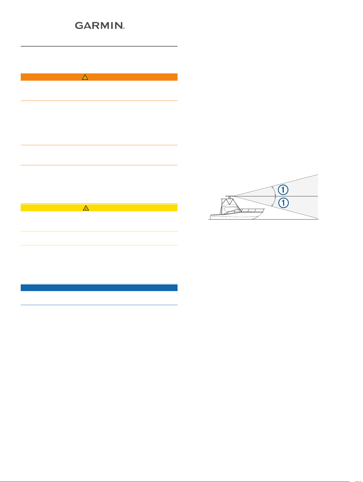
• The radar beam spreads vertically 11.5° above and
11.5° below À the radar's radiating element. On vessels with
higher bow angles at cruise speed, the installation angle can
be lowered to point the beam slightly downward to the
waterline while at rest. Shims can be used if necessary.
• The device should be mounted away from heat sources, such
as smoke stacks and lights.
• The device should be mounted at a different level than
horizontal spreaders and mast crosstrees.
• To avoid interference with a magnetic compass, the device
should not be mounted closer to a compass than the
compass-safe distance value listed in the product
specifications.
• Other electronics and cables should be mounted more than
2 m (6.5 ft.) from the radar beam path.
• GPS antennas should be either above or below the radar
beam path.
• The device should be mounted at least 1 m (40 in.) from any
transmitting equipment.
• The device should be mounted at least 1 m (40 in.) away
from cables carrying radio signals such as VHF radios,
cables, and antennas.
• The device should be mounted at least 2 m (6.5 ft.) away
from Single Side Band (SSB) radios.
Preparing the Surface and the Radar for Mounting
Before you can mount the radar, you must choose a suitable
mounting location (Mounting Considerations, page 1).
Secure the included mounting template to the surface at the
1
mounting location, along the bow-stern axis, as indicated on
the template.
Drill the mounting holes using a 15 mm (19/32 in.) drill bit.
2
If you need to run the power and network cables through the
3
mounting surface, select a location under the power and
network connectors indicated on the template, drill a passthrough hole for the cables using a 32 mm (11/4 in.) drill bit,
and route the cables through the surface (optional) (Cable
Considerations, page 2).
Remove the mounting template from the surface.
4
January 2017
Printed in Taiwan 190-01818-02_0C
Remove the hatch on the front of the pedestal by loosening
5
the screw and lifting the hatch off of the hinges.
Apply the included Petrolatum Primer to one half of the
6
threads of the four threaded rods.
Insert the ends of the threaded rods coated in Petrolatum
7
Primer into the pedestal.
Tighten the threaded rods using a 5 mm hex wrench.
8
To avoid damaging the pedestal, you should stop tightening
the threaded rods when they no longer turn easily.
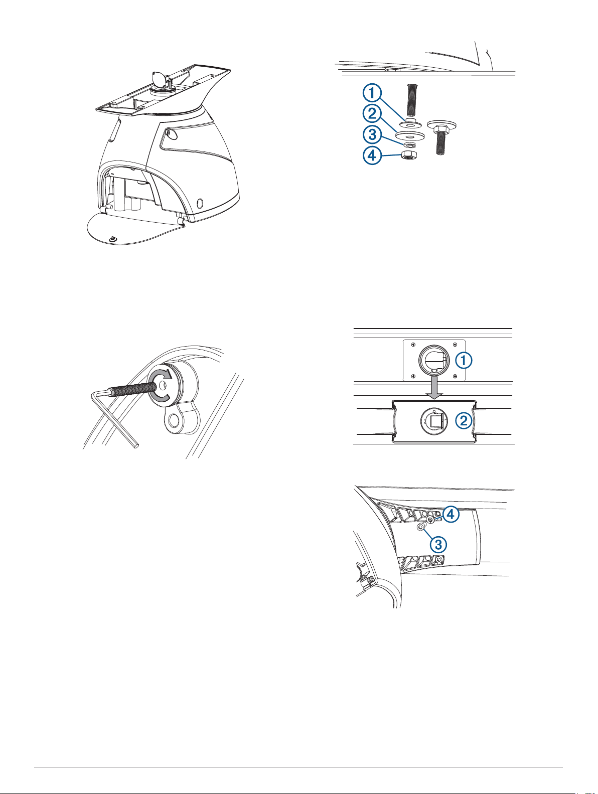
Place the flat washers Á, lock washers Â, and hex nuts à on
4
the threaded rods.
Torque the hex nuts to 1.5 kgf-m (130 lbf-in. [11 lbf-ft.]) to
5
securely fasten the radar to the surface without damaging the
radar or the mounting hardware.
Installing the Antenna
Before you can install the antenna on the radar, you must
securely mount the pedestal (Mounting the Radar, page 2).
Remove the protective cover from the waveguide on the top
1
of the pedestal.
Align the waveguide À on the pedestal with the socket on the
2
bottom of the antenna Á, and slide the antenna onto the
pedestal.
Mounting the Radar
Before you can mount the radar, you must first select a
mounting location, and prepare the mounting surface and the
radar (Preparing the Surface and the Radar for Mounting,
page 1).
Take note of which end of the pedestal you plan to mount
1
facing the bow along the bow-stern axis.
If the hatch side is facing the bow, you must adjust the front-
of-boat offset on the chartplotter to receive an accurate radar
reading (Front-of-Boat Offset, page 4).
Hoist the radar into position, and carefully lower it onto the
2
mounting surface, feeding the threaded rods through the
holes.
From under the mounting surface, place the shoulder
3
washers À on the threaded rods and feed them into the
mounting surface so they fit securely.
Secure the antenna to the pedestal using the included hex
3
bolts  and spring washers Ã.
Torque the hex bolts to 0.81 kgf-m (70 lfb-in. [6 lbf-ft.]) to
4
fasten the antenna to the pedestal without damaging the
antenna or the mounting hardware.
Cable Considerations
It may be necessary to drill 32 mm (11/4) in. holes for routing the
power or network cables.
• When routing both the power and network cables through the
same hole, you must route the network cable before the
power cable.
• You must apply marine sealant to the hole after the cables
are in place to ensure a waterproof seal.
2
If the routing hole must be made in a visible location, decorative
cable grommets can be purchased from Garmin or a Garmin
dealer (optional).
• If needed, the grommet can be trimmed to enable you to
route both the network and the power cable through the
same hole.
• The optional grommet does NOT provide a waterproof seal.
You must apply marine sealant to the grommet after the
cables are in place to ensure a waterproof seal.
When installing the network and power cables, you should
observe these considerations.
• Cutting the Garmin Marine Network cable is not
recommended, but a field install kit can be purchased from
Garmin or a Garmin dealer if cutting the network cable is
necessary.
• To ensure safety, appropriate tie-wraps, fasteners, and
sealant should be used to secure the cable along the route
and through any bulkheads or the deck.
• Cables should not be run near moving objects and high-heat
sources or through doorways and bilges.
• To avoid interference with other equipment, network and
power cables should not be run next to or parallel to other
cables, such as radio antenna lines or power cables. If this is
not possible, the cables should be shielded with metal
conduit or a form of EMI shielding.
• The power cable should be installed as close to the battery
source as possible.
◦ If it is necessary to extend the power cable, the
appropriate gauge of wire must be used (Power Cable
Extensions, page 4).
◦ Incorrectly extended runs of cable may cause the radar to
malfunction due to insufficient power transmission.
Connecting to Power Through the Voltage Converter
WARNING
When connecting the power cable, do not remove the in-line
fuse holder. To prevent the possibility of injury or product
damage caused by fire or overheating, the appropriate fuse
must be in place as indicated in the product specifications. In
addition, connecting the power cable without the appropriate
fuse in place voids the product warranty.
NOTICE
Do not reuse any voltage converters from previous Garmin radar
models, or third party voltage converters. Using any converter
other than one included with the radar may damage the radar or
prevent it from turning on.
Some radar models require a voltage converter unit to properly
power the device. If your model is packaged with a voltage
converter, it must be installed in order for your radar to function.
If your model is not packaged with a voltage converter, connect
the power cable directly to the boat battery (Connecting Directly
to Power, page 3).
When installing the voltage converter for an applicable radar
model, observe these considerations.
• The voltage converter requires an input voltage of 10 to
32 Vdc.
• It is recommended to install the voltage converter as close as
possible to the power source.
• Connecting the power cable for the voltage converter directly
to the battery is recommended. If it is necessary to extend
the cable, the appropriate gauge of wire must be used for the
length of the extension (Power Cable Extensions, page 4).
Item Description
À
Á
Â
Ã
Ä
Å
1
2
3
4
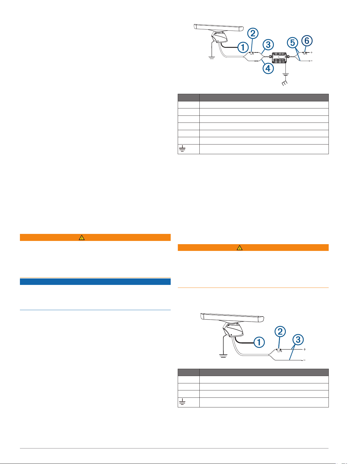
To the Garmin Marine Network
10 A fuse holder
Red (+)
Black (-)
To the boat battery (10 to 32 Vdc)
30 A fuse holder
Water ground connection
Route the power cable to the radar and the voltage converter.
Use crimp connectors and heat-shrink tubing to connect the
power cable to the voltage converter.
The radar power cable contains a 10 A fuse which should not
be removed when connecting to the voltage converter.
Connect the voltage converter to the boat battery through the
included 30 A fuse.
The 30 A fuse between the voltage converter and battery is in
addition to the 10 A fuse included in the radar power cable.
Both fuses must be in place for the radar to function properly.
Connect the power cable to the POWER port on the radar.
Connecting Directly to Power
WARNING
When connecting the power cable, do not remove the in-line
fuse holder. To prevent the possibility of injury or product
damage caused by fire or overheating, the appropriate fuse
must be in place as indicated in the product specifications. In
addition, connecting the power cable without the appropriate
fuse in place voids the product warranty.
Some radar models do not require a voltage converter unit. If
your model is packaged without a voltage converter, it should be
connected directly to power.
Item Description
À
Á
Â
1
2
3
To the Garmin Marine Network
15 A fuse holder
To the boat battery (10 to 32 Vdc)
Water ground connection
Route the power cable to the radar and boat battery.
Connect the power cable to the boat battery.
Connect the power cable to the POWER port on the radar.
3
 Loading...