

Garmin GMR 21, GMR 41 User Manual
GMR 21/41
marine radar
Owner’s Manual

© Copyright 2006 Garmin Ltd. or its subsidiaries
Garmin International, Inc.
1200 East 151st Street,
Olathe, Kansas 66062, U.S.A.
Tel. 913/397.8200 or 800/800.1020
Fax 913/397.8282
All rights reserved. Except as expressly provided herein, no part of this manual may be reproduced, copied, transmitted, disseminated, downloaded or stored in any
storage medium, for any purpose without the express prior written consent of Garmin. Garmin hereby grants permission to download a single copy of this manual onto
a hard drive or other electronic storage medium to be viewed and to print one copy of this manual or of any revision hereto, provided that such electronic or printed
copy of this manual must contain the complete text of this copyright notice and provided further that any unauthorized commercial distribution of this manual or any
revision hereto is strictly prohibited.
Information in this document is subject to change without notice. Garmin reserves the right to change or improve its products and to make changes in the content
without obligation to notify any person or organization of such changes or improvements. Visit the Garmin Web site (www.garmin.com) for current updates and
supplemental information concerning the use and operation of this and other Garmin products.
Garmin® is a registered trademarks of Garmin Ltd. or its subsidiaries and may not be used without the express permission of Garmin.
March 2006 Part Number 190-00665-00 Rev. A Printed in Taiwan
Garmin (Europe) Ltd.
Unit 5, The Quadrangle
Abbey Park Industrial Estate
Romsey, SO51 9DL, U.K.
Tel. 44/0870.8501241
Fax 44/0870.8501251
Garmin Corporation
No. 68, Jangshu 2nd Road
Shijr, Taipei County, Taiwan
Tel. 886/2.2642.9199
Fax 886/2.2642.9099

INTRODUCTION > ABOUT THIS MANUAL
INTRODUCTION
About This Manual
Thank you for choosing Garmin’s GMR 21/41 marine radar. The
addition of the GMR 21/41 marine radar to your Garmin Marine
Network, enhances the capability of your system by adding graphical
radar data to your Garmin chartplotter.
This manual covers the features and operation of the GMR 21/41
marine radar when viewed on the Garmin chartplotters. To get the
most out of your new radar, take time to read this manual and learn
the operating procedures for your unit in detail.
The Introduction contains information about this manual and the
Table of Contents.
The Main Pages contain information on the setup and operation of the
GMR 21/41.
The Appendix contains information such as specifications and license
requirements. You can also find warranty and FCC information in the
Appendix.
Use the Index as a key word search to help you find information more
quickly.
Terminology Used Throughout This Manual
• This manual refers to the radome hardware as the “scanner,”
“radar,” or “GMR 21/41.” These terms can be used
interchangeably.
• This manual uses the term “chartplotter” when referring to a
Garmin GPSMAP 3000 series multi-function display.
• This manual uses the term “Radar Page.” The Radar Page is
a dedicated page on the Garmin chartplotter showing radar
information. Radar information can be displayed as a split
screen on any of the chartplotter main pages.
• This manual uses the term “
on-screen cursor. To highlight something, use the Rocker key
on the chartplotter to move the cursor to the desired item. The
on-screen cursor is represented by a highlighted yellow box.
highlight” when referring to the
GMR 21/41 Owner’s Manual i

INTRODUCTION > TABLE OF CONTENTS
Introduction ...........................................................................i
About This Manual ................................................................... i
Terminology used Throughout this Manual ........................... i
GMR 21/41 Operation ..........................................................1
Radar Overview ....................................................................... 1
The Radar Page ....................................................................... 1
Radar Page Layout .......................................................................... 3
Range Rings ..............................................................................4
Heading Line ............................................................................. 4
Digital Navigation Data ............................................................ 4
The Radar Configuration Page ............................................... 5
The Radar Adjustment Menu .................................................. 5
Gain ................................................................................................ 6
Sea Clutter ......................................................................................6
Rain Clutter ..................................................................................... 7
FTC (Fast Time Constant) .............................................................. 7
Zoom ............................................................................................... 8
Target Expansion ............................................................................ 8
Trails ............................................................................................... 9
Guard Zone ..................................................................................... 9
VRM/EBL ..................................................................................... 10
MARPA ......................................................................................... 11
MARPA Setup ............................................................................. 12
Hide/Show Navigation Features ................................................... 13
Additional Adjustment Menu Items ............................................. 13
Map Cursor On/Off ....................................................................... 14
Setup .............................................................................................14
The General Tab ...................................................................... 14
The Display Tab ...................................................................... 15
The MARPA Tab ..................................................................... 16
The Advanced Tab .................................................................. 16
Enter Standby/Begin Transmitting ...............................................17
Map Page Radar Overlay ...................................................... 17
Appendix ............................................................................19
European License Requirements ........................................ 19
Specifications ........................................................................ 20
FCC Compliance .................................................................... 21
Declaration of Conformity .................................................... 21
Software License Agreement ............................................... 22
Limited Warranty ................................................................... 22
Warning and Cautions .......................................................... 24
ii GMR 21/41 Owner’s Manual
GMR 21/41 OPERATION > RADAR OVERVIEW—THE RADAR PAGE
GMR 21/41 OPERATION
When the new radar is detected, the chartplotter automatically
adds a dedicated Radar Page to the pages list. If the Radar Page is
Radar Overview
The Garmin GMR 21/41 transmits a narrow beam of microwave
energy in a rotating 360° pattern. When the transmitted energy
contacts a target, some of that energy is reflected and returned to
the scanner. The scanner collects the returned energy for processing
and display. The GMR 21/41 is operated and adjusted using controls
on the Gamin chartplotter. Radar data is presented on a dedicated
Radar Page or as an overlay on the Map page. All radar controls are
not available, press and hold ADJ/MENU until the Main Menu is
displayed. Use the Rocker to highlight the System tab, and select
Radar from the Services list at the bottom of the page.
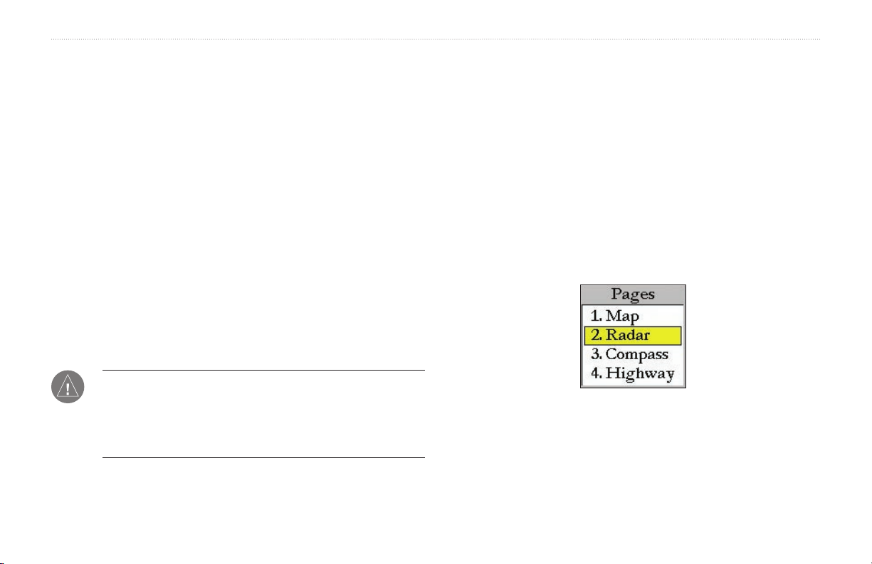
To Select the Radar Page for display:
1. Press PAGE to display the Pages list.
2. Using the Rocker, select Radar.
3. Press ENTER.
accessible on both pages.
The Radar Page
With the GMR 21/41 radar properly installed, at power up, the
Garmin chartplotter should detect the GMR 21/41 as a new network
connection.
NOTE: A software update may be needed for the GMR 21/41
to function properly. If the message “Incompatible Software
Version” is displayed when the chartplotter is powered on, the
software in the chartplotter needs to be updated. A software
update card is provided with the GMR 21/41.
Pages List
GMR 21/41 Owner’s Manual 1
GMR 21/41 OPERATION >THE RADAR PAGE
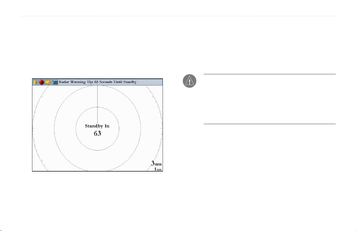
When the scanner is powered on, the Status Bar at the top of the
Radar Page, shows the message “Radar Warming Up” with a
countdown to Standby Mode. The countdown is also displayed in
the middle of the Radar Page. When the countdown reaches zero, the
message changes to “Hold FCTN to transmit.”
As a safety feature, the scanner enters standby mode after it warms
up. This provides the operator an opportunity to verify that the area
around the scanner is clear before beginning radar transmission. It is
important to remember that the microwave energy transmitted by the
scanner can potentially be dangerous.
CAUTION: The GMR 21/41 radar transmits microwave energy
When the area surrounding the scanner is clear, press and hold
FCTN. The message “Do you want to begin radar transmission?”
is displayed. Select Yes, then press ENTER. Before transmission
begins, the message “Spinning Up” is shown while the radar antenna
reaches nominal rotation speed. When the message disappears, the
radar begins painting an image.
that has the potential to be harmful to humans and animals. Before
beginning radar transmission, verify that the area around the
scanner is clear. The GMR 21/41 transmits a beam approximately
12° above and below a line extending horizontally from the center
of the scanner. Avoid looking directly at the scanner, the eyes are
the most susceptible part of the body.
2 GMR 21/41 Owner’s Manual
GMR 21/41 OPERATION > RADAR PAGE LAYOUT
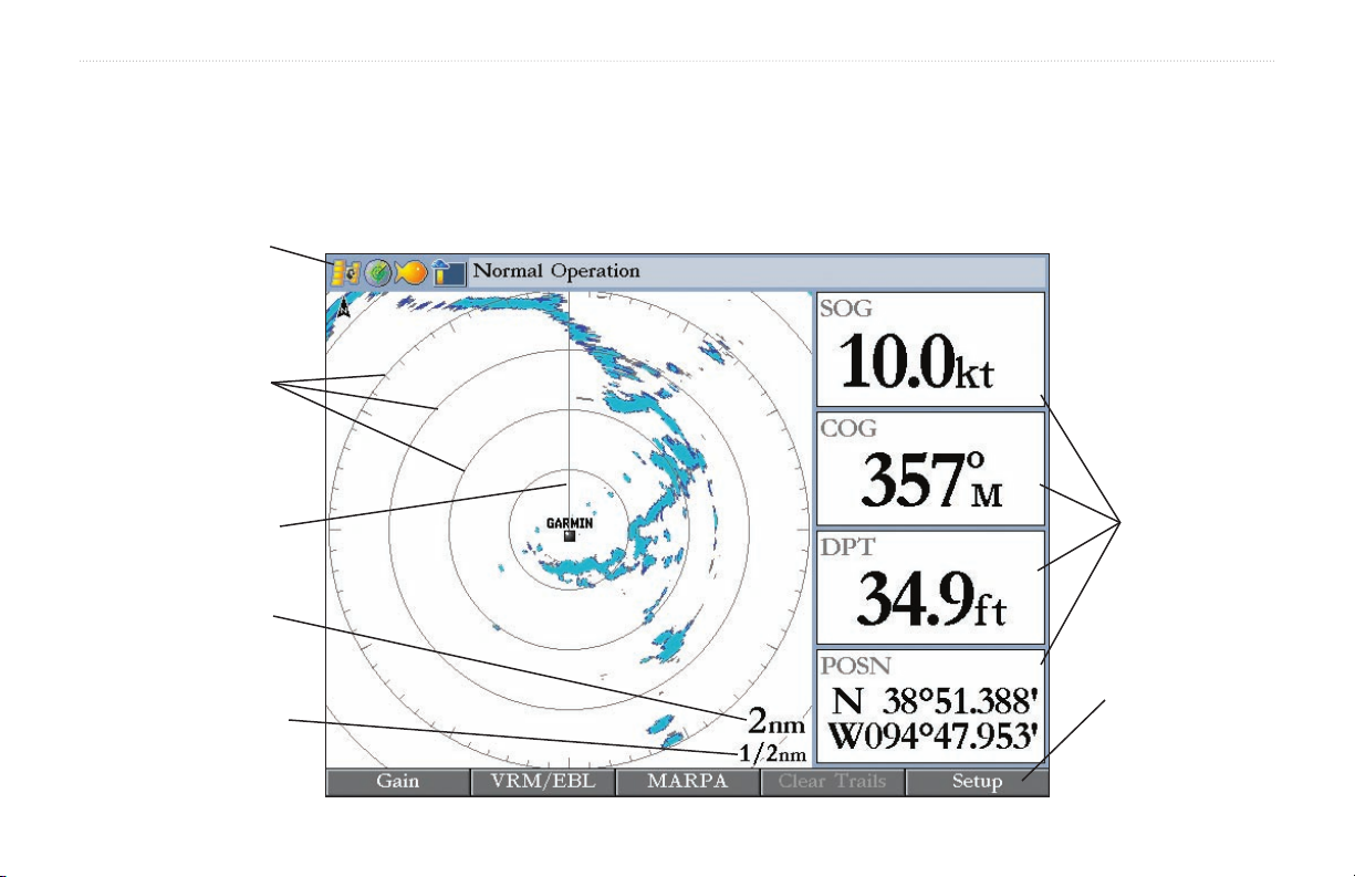
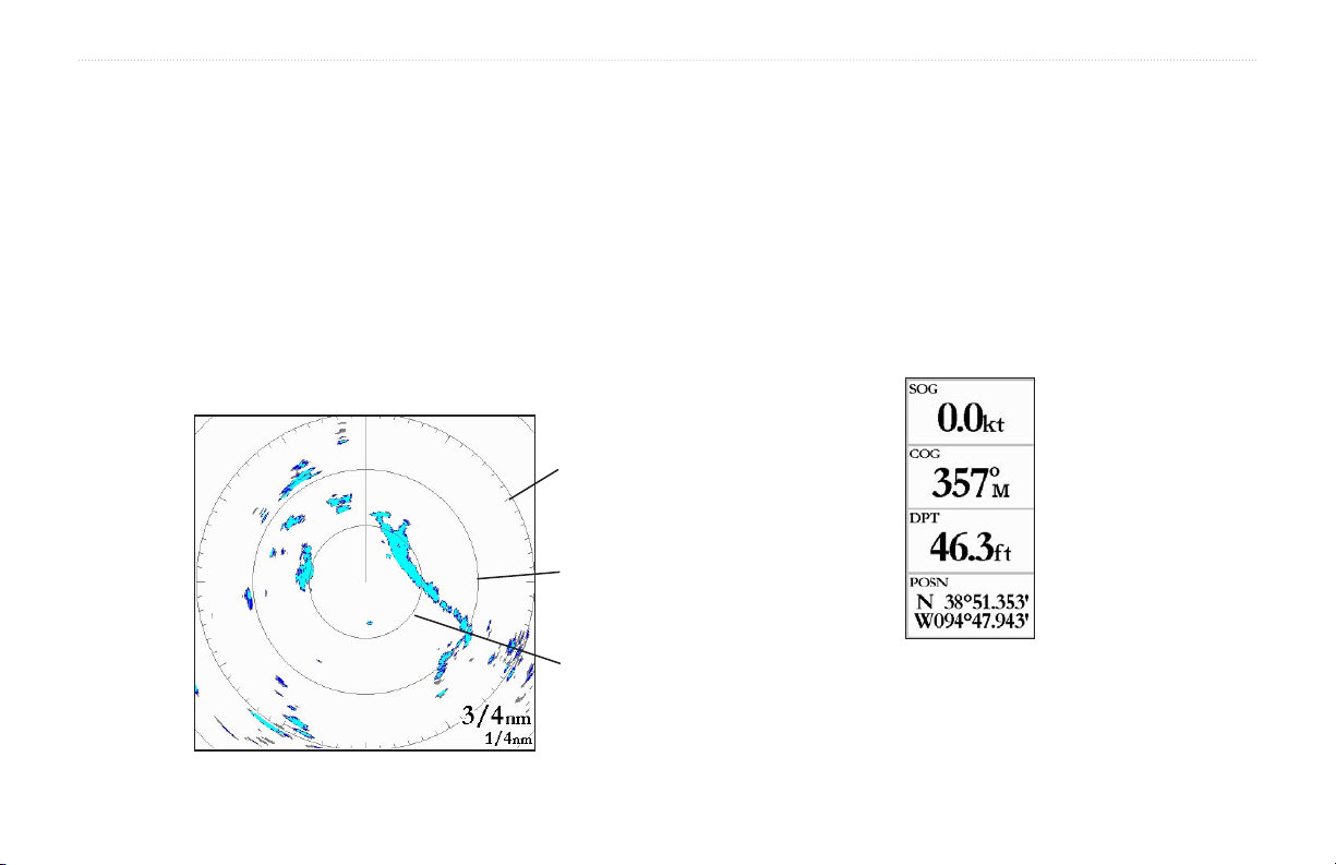
Radar Page Layout
This section describes the features of the Radar Page and how its features are displayed. By default, the Radar Page displays a Status Bar along
the top, user configurable Digital Navigation Data down the right side, a Heading Line, and Range Rings. Soft key options that allow quick
access to radar functions and setting changes are displayed along the bottom of the page.
Status bar
Range rings
Heading line
Zoom scale
Ring separation
GMR 21/41 Owner’s Manual 3
Digital
navigation
data
Soft key options
GMR 21/41 OPERATION > RANGE RINGS—HEADING LINE—DIGITAL NAVIGATION DATA
Range Rings
The Range Rings help to quickly determine the distance to a target. In
the lower-right corner of the display are two scales. The upper scale
Heading Line
The Heading Line is shown from your current position along the path
of your current heading.
is the current zoom scale. This scale is changed using the RANGE
keys. The zoom scale is represented by the Range Ring with tick
marks around the circumference. The tick marks are arranged with
major tick marks at thirty-degree increments and minor tick marks
every five degrees. The tick marks can help in quickly determining
the azimuth to a target. The lower scale represents the distance
Digital Navigation Data
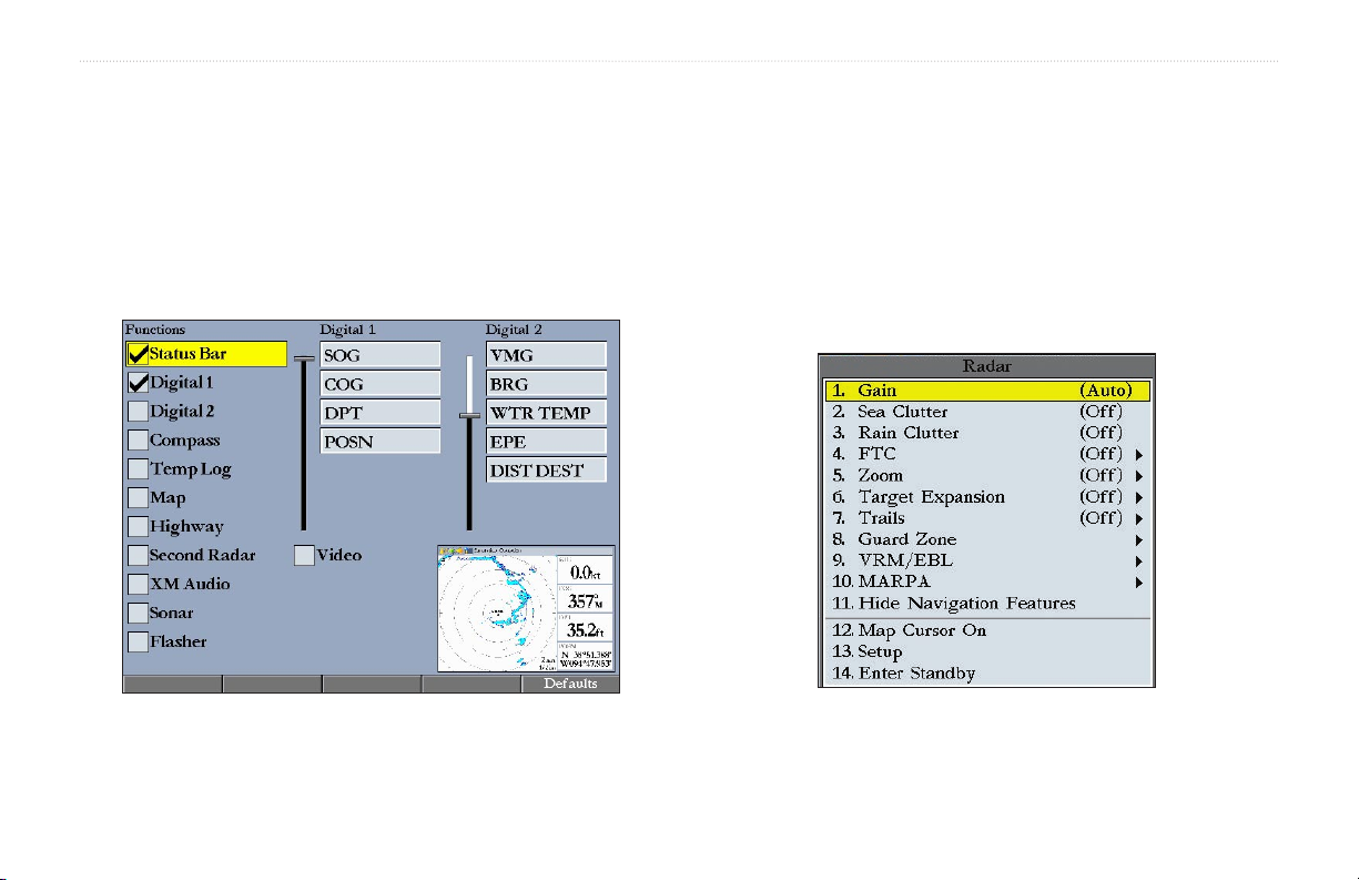
By default, the Radar Page shows one column of digital navigation
data with four data fields. The Radar Page can be configured to show
two columns of data with up to seven data fields each. Each data field
can be configured to show a variety of data.
between the Range Rings.
3/4 nm
1/2 nm
1/4 nm
4 GMR 21/41 Owner’s Manual
GMR 21/41 OPERATION > THE RADAR CONFIGURATION PAGE—THE RADAR ADJUSTMENT MENU
The Radar Configuration Page
The Radar Configuration Page is used to change the look of the Radar
Page. Please refer to the GPSMAP 3000 series owner’s manual for
information about “Configuring the Main Pages.”
To display the Radar Configuration Page:
Press and hold DATA\CONFIG.
The Radar Adjustment Menu
The Radar Adjustment Menu is a numbered list of options that allows
direct access to the settings and features most commonly used on the
Radar Page. There are several adjustment options available: Gain, Sea
Clutter, Rain Clutter, FTC, Zoom, Target Expansion, Trails, Guard
Zone, VRM/EBL, MARPA, and Hide/Show Navigation Features. All
adjustments are made using the Rocker, or Data Entry keys.
Radar Configuration Page
Radar Adjustment Menu
GMR 21/41 Owner’s Manual 5
GMR 21/41 OPERATION > THE RADAR ADJUSTMENT MENU
To change a Radar Adjustment Menu setting:
1. Press ADJ/MENU to display the Adjustment Menu.
2. Use the Rocker or Data Entry keys to select an option. Press
ENTER to display the adjustment for that selection.
3. Use the Rocker to change the current setting. Press ENTER
to accept the change.
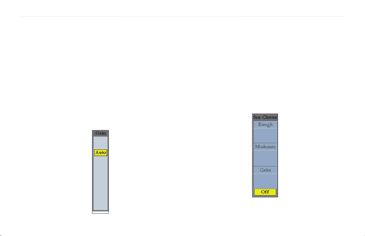
Gain
Selecting Gain displays the Gain adjustment slider. When Auto
is selected, the scanner’s gain is automatically adjusted to provide
optimal performance. Manually adjusting the gain increases or
decreases the receiver’s sensitivity. Increasing the gain may help to
show a distant target, but may also increase screen clutter.
To change the Gain setting:
1, Use the Rocker to move the slider up or down.
2. Press ENTER to accept the change.
To return the Gain setting to Auto, move the slider to the Auto
position, or press the Auto soft key.
Sea Clutter
Adjusting the Sea Clutter setting can help eliminate any unwanted
screen clutter caused by choppy sea conditions. Selecting Sea Clutter
displays the Sea Clutter adjustment slider. The slider has three preset
positions: Calm, Moderate, and Rough.
6 GMR 21/41 Owner’s Manual
 Loading...