

Garmin ECHOMAP PLUS 60 series, ECHOMAP PLUS 90 series, ECHOMAP PLUS 70 series Installation Instructions Manual
ECHOMAP™ PLUS 60/70/90
SERIES
Installation Instructions
Important Safety Information
WARNING
See the Important Safety and Product Information guide in the
product box for product warnings and other important
information.
When connecting the power cable, do not remove the in-line
fuse holder. To prevent the possibility of injury or product
damage caused by fire or overheating, the appropriate fuse
must be in place as indicated in the product specifications. In
addition, connecting the power cable without the appropriate
fuse in place voids the product warranty.
CAUTION
Always wear safety goggles, ear protection, and a dust mask
when drilling, cutting, or sanding.
NOTICE
When drilling or cutting, always check what is on the opposite
side of the surface.
Before permanently installing any part of your device, you
should plan the installation by determining the location of the
various components.
• The mounting location must provide a clear view of the
screen and access to the keys on the device.
• The mounting location must be sturdy enough to support the
device and the mount.
• The cables must be long enough to connect the components
to each other and to power.
• To avoid interference with a magnetic compass, do not install
the device closer to a compass than the compass-safe
distance value listed in the product specifications.
Fixed-Bail Mounting the Device
NOTICE
If you are mounting the bracket on fiberglass with screws, it is
recommended to use a countersink bit to drill a clearance
counterbore through only the top gel-coat layer. This will help to
avoid cracking in the gel-coat layer when the screws are
tightened.
Stainless-steel screws may bind when screwed into fiberglass
and overtightened. It is recommended to apply an anti-seize
lubricant on the screws before installing them.
Select the mounting hardware appropriate for your mounting
1
surface and for the bail-mount bracket.
Using the bail-mount bracket as a template, mark the pilot
2
holes through the screw holes.
Using a drill bit appropriate for the mounting hardware, drill
3
the four pilot holes.
Using the selected mounting hardware, secure the bail-mount
4
bracket to the mounting surface.
Install the bail-mount knobs À on the sides of the cradle.
5
To obtain the best performance and to avoid damage to your
boat, install the device according to these instructions.
Read all installation instructions before proceeding with the
installation. If you experience difficulty during the installation,
contact Garmin® Product Support.
Tools Needed
• Drill
• Drill bits
◦ Bail mount: drill bits appropriate for the surface and
hardware
◦ Swivel mount: 3 mm (1/8 in.) drill bit
◦ Flush mount: 3 mm (1/8 in.) and 9.5 mm (3/8 in.) drill bits
• #2 Phillips screwdriver
• Jigsaw or rotary tool
• File and sandpaper
• Marine sealant (optional)
Mounting Considerations
You can mount the device using one of three methods.
Bail mount: You can mount the device using the bail mount,
which allows you to tilt the device.
Swivel mount: You can mount the device using the swivel base
and bail mount, which allows you to swivel and tilt the device.
Not available on the ECHOMAP Plus 90 models.
Flush mount: You can mount the device in the dashboard,
which provides a more integrated installation.
Place the cradle into the bail-mount bracket Á, and tighten
6
the bail-mount knobs.
Connect each cable to a port on the cradle, using the locking
7
bracket or locking rings to secure the cables to the cradle
(Installing the Cables and Connectors, page 2).
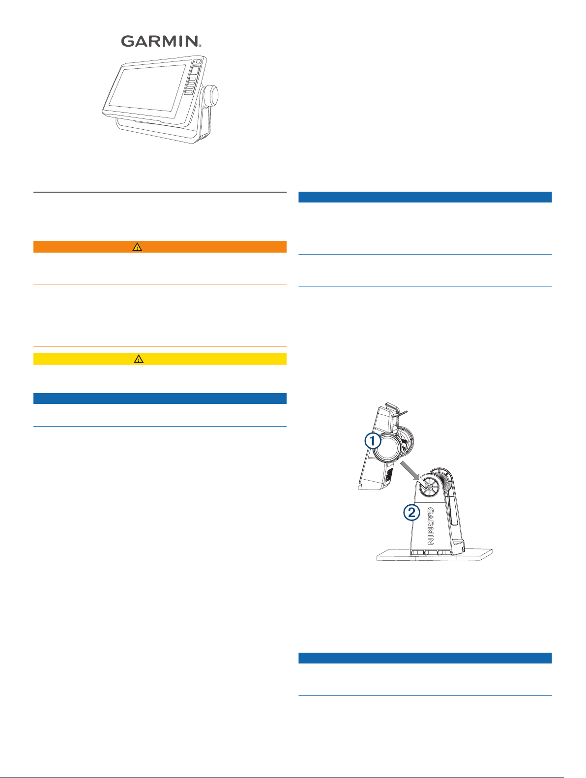
Bail Mounting a Device with a Swivel Base
NOTICE
Only pan-head machine bolts or self-tapping screws should be
used to secure the swivel base. If you use screws with
countersunk heads, you may damage the mounting bracket.
Some models have the option of adding a swivel base to the bail
mount, so you can turn the device for a wider range of viewing
angles.
December 2017
190-02243-02_0B
NOTE: The ECHOMAP Plus 90 models do not have a swivel
option.
Using the swivel base À as a template, mark three pilot holes
1
.
Á
Using a 3 mm (1/8 in.) drill bit, drill the three pilot holes.
2
Using the included wood screws Â, secure the swivel base to
3
the mounting surface.
Place the bail-mount bracket à on the swivel base, and
4
secure it using the swivel-mount knob Ä.
Install the bail-mount knobs Å on the sides of the cradle.
5
Place the device in the bail-mount bracket and tighten the
6
bail-mount knobs.
Connect each cable to a port on the cradle, using the locking
7
bracket or locking rings to secure the cables to the cradle
(Installing the Cables and Connectors, page 2).
Ensure the mounting holes on the device line up with the pilot
8
holes on the template.
If the mounting holes on the device do not line up with the
9
pilot holes on the template, mark the new pilot-hole locations
on your template.
Using a 3 mm (1/8 in.) drill bit, drill the pilot holes.
10
Remove the template from the mounting surface.
11
Place the device in the cradle.
12
NOTE: You must use the cradle and locking bracket or
locking rings when you flush-mount the device.
If you will not have access to the back of the device after you
13
mount it, connect all necessary cables to the cradle and
secure the cables with the locking bracket or locking rings
before placing the device into the cutout (Installing the
Cables and Connectors, page 2).
To prevent corrosion of the metal contacts, cover unused
14
connectors with weather caps (ECHOMAP Plus 70/90
models only).
Install the rubber gasket pieces on the back of the device.
15
The pieces of the rubber gasket have adhesive on the back.
Make sure you remove the protective liner before installing
them on the device.
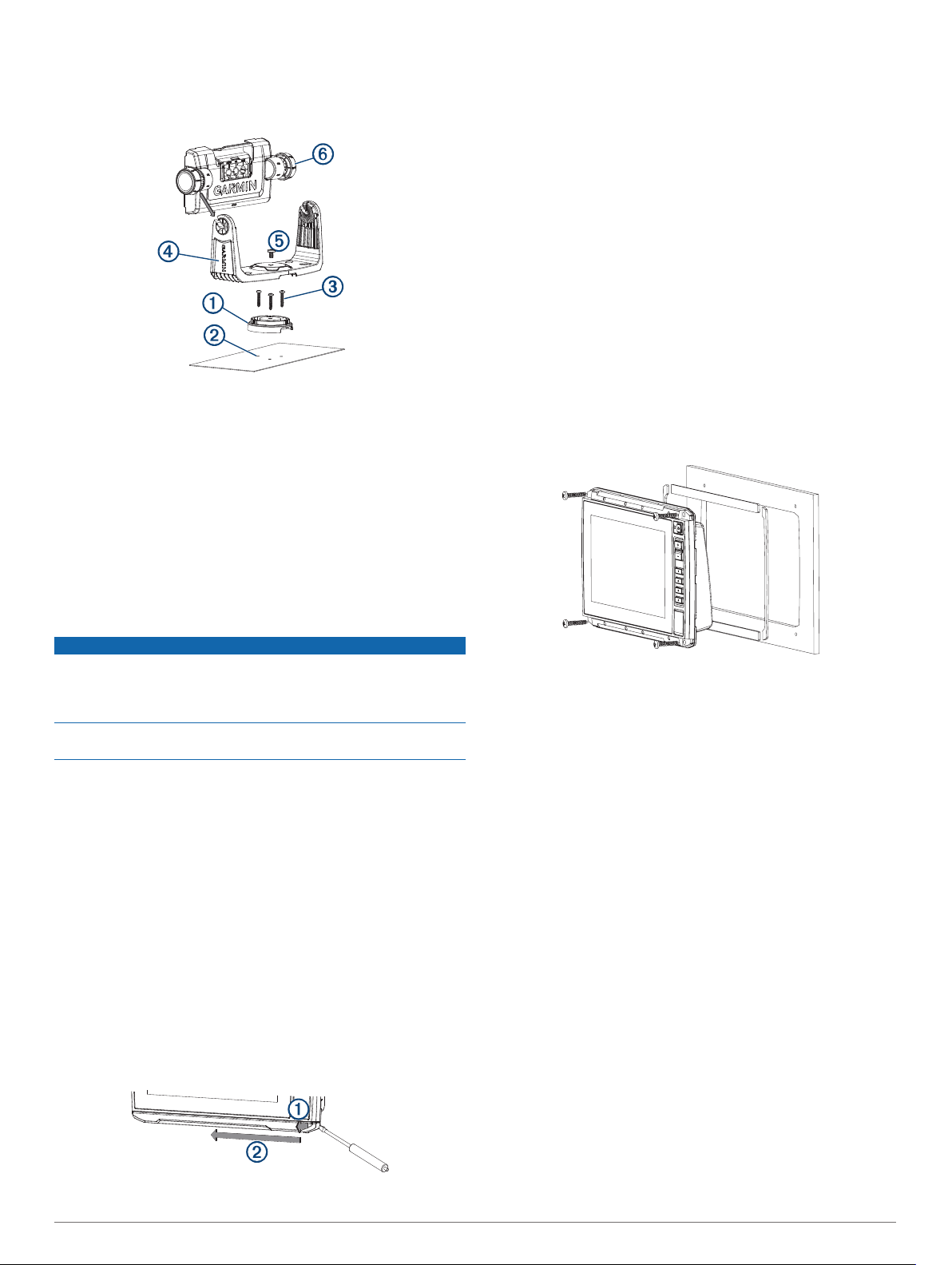
Flush Mounting the Device
NOTICE
Be careful when cutting the hole to flush mount the device.
There is only a small amount of clearance between the case and
the mounting holes, and cutting the hole too large could
compromise the stability of the device after it is mounted.
Using a metal pry tool such as a screwdriver can damage the
trim caps and the device. Use a plastic pry tool when possible.
You can mount the device in your dashboard using the flushmount template and appropriate hardware.
Trim the template and make sure it fits in the location where
1
you want to mount the device.
Secure the template to the mounting location.
2
Using a 9.5 mm (3/8 in.) drill bit, drill one or more of the holes
3
inside the corners of the solid line on the template to prepare
the mounting surface for cutting.
Using a jigsaw or rotary cutting tool, cut the mounting surface
4
along the inside of the solid line indicated on the template.
Place the device into the cutout to test the fit.
5
If necessary, use a file and sandpaper to refine the size of
6
the hole.
If your device has trim caps, use a pry tool, such as a flat
7
piece of plastic or a screwdriver, to carefully pry up the
corners of the trim caps À, slide the pry tool to the center Á,
and remove the trim caps.
Connect each cable to a port on the cradle, using the locking
16
bracket or locking rings to secure the cables to the cradle
(Installing the Cables and Connectors, page 2).
Place the device and cradle into the cutout.
17
Secure the device to the mounting surface using the included
18
screws.
Install the trim caps by snapping them in place around the
19
edges of the device.
Installing the Cables and Connectors
Wiring to Power
Route the power cable from the mount to the boat battery or
1
fuse block.
If necessary, extend the wires using 0.82 mm2 (18 AWG) or
2
larger wire.
Connect the red wire to the positive terminal on the battery or
3
fuse block, and connect the black wire to the negative
terminal.
Wiring Harness
• The wiring harness is used for NMEA® 0183 devices, and to
share route and waypoint information.
• The wiring harness connects the device to power and NMEA
0183 devices.
• The device has one internal NMEA 0183 port that is used to
connect to NMEA 0183 compliant devices.
• If it is necessary to extend the power and ground wires, you
must use 0.82 mm2 (18 AWG) or larger wire.
• If it is necessary to extend the NMEA 0183 or alarm wires,
you must use .33 mm2 (22 AWG) wire.
2
 Loading...