


GMR 20/40
marine radar
installation guide

© Copyright 2004 Garmin Ltd. or its subsidiaries. All Rights Reserved
Garmin International, Inc.
1200 E 151st Street, Olathe, Kansas 66062
U.S.A.
Tel. 913/397.8200
Fax. 913/397.8282
Garmin (Europe) Ltd.
Unit 5, The Quadrangle, Abbey
Park Industrial Estate, Romsey,
SO51 9AQ U.K.
Tel. 44/0870.8501241
Garmin Corporation
No. 68, Jangshu 2nd Road, Shijr, Taipei
County, Taiwan
Tel. 886/2.2642.9199
Fax. 886/2.2642.9099
Fax. 44/0870.8501251
Except as expressly provided herein, no part of this manual may be reproduced, copied, transmitted, disseminated, downloaded or stored in any
storage medium, for any purpose without the express prior written consent of Garmin. Garmin hereby grants permission to download a single
copy of this manual and of any revision to this manual onto a hard drive or other electronic storage medium to be viewed and to print one copy
of this manual or of any revision hereto, provided that such electronic or printed copy of this manual or revision must contain the complete
text of this copyright notice and provided further that any unauthorized commercial distribution of this manual or any revision hereto is strictly
prohibited.
Information in this document is subject to change without notice. Garmin reserves the right to change or improve its products and to make
changes in the content without obligation to notify any person or organization of such changes or improvements.
Web site address: www.garmin.com
GARMIN® is a registered trademarks of Garmin Ltd. or its subsidiaries and may not be used without the express permission of Garmin.
October 2004 Part Number 190-00457-02 Rev. A Printed in Taiwan

WELCOME
Thank you for choosing the Garmin GMR 20/40. The GMR 20/40 utilizes the performance of Garmin radar and provides overlay and color
information when combined with a marine Multi-Function Display (MFD).
Contact Garmin
If you should encounter any difficulty while using your GMR 20/40, or if you have any questions, in the U.S.A. contact Garmin Product
Support by phone: 913/397-8200 or 800/800-1020, Monday thru Friday, 8 am to 5 pm Central Time; or by e-mail at sales@garmin.com. In
Europe, contact Garmin (Europe) Ltd. at 44/0870.8501241.
Product Support Registration
Help us better support you by completing our on-line registration today! Have the serial number of your GMR 20/40 handy and connect to our
Web site (www.garmin.com). Look for the Product Registration link on the Home page. Also, be sure to record your serial number in the area
provided on this page.
Serial Number
Use this area to record the serial number in case it is lost, stolen, needs service, or if you need to contact Product Support. The 8-digit number is
located on the bottom of the unit and on the outside of the product box. It is advisable to record this number prior to installation of the scanner.
Be sure to keep your original sales receipt in a safe place or attach a photocopy inside the manual.
Serial Number:
NOTE: The Garmin GMR 20/40 has no user-serviceable parts. Should you ever encounter a problem with your unit, please take it to an authorized
Garmin NMEA dealer or contact Garmin Customer Service for repairs.
Packing List
Before installing and getting started with your unit, please check to see that your package includes the following items. If any parts are
missing, please contact your Garmin dealer immediately.
Standard Package:
• GMR 20 or 40 Radar Unit
• Power/Marine Network Cable
• Installation Manual
• Mount Kit Hardware
• Grommet for Marine Cable
GMR 20/40 Radar Installation Manual
1
Scanner Installation
The following section covers the installation and setup of the GMR 20 (2 kW) and GMR 40 (4 kW) Marine Radars. The GMR 20 and 40 only
operate with components of the Garmin Marine Network with compatible MFD (Mulit-Function Displays). See your Garmin dealer or the
Garmin web site for more details. To complete the installation, you will need the appropriate fasteners, tools, and mounts. These items should
be available at most marine dealers. Always wear safety goggles, ear protection, and a dust mask when drilling, cutting, or sanding. When
drilling or cutting, always check first to see what is on the other side of the surface. When in doubt, seek professional assistance.
Installation Guidelines
In order to maximize the performance of the radar, please observe the following installation guidelines:
• An ideal scanner mounting location is high above the ship’s keel line with a minimal part of the vessel’s structure or rigging blocking
the radar beam. Obstructions in the path of the radar beam may cause blind/shadow sectors or generate false echoes. The higher the
installation position, the further the scanner can detect targets.
• Avoid mounting the scanner on the same level as smoke stacks or horizontal spreaders/crosstrees on a mast. Do not install the scanner
near heat sources where it may be subjected to smoke or hot air from smoke stacks or heat from lights.
• The mounting surface/platform should be sturdy enough to support the weight of the scanner (26 lbs.), flat as possible, and parallel with
the vessel’s water line.
• It is recommended that the radar scanner is mounted out of range of personnel (horizontial beam width above head height). Do not look
directly at the antenna at close range as your eyes are the most sensitive part of the body to electromagnetic energy. When properly
installed and operated, the use of this radar will conform to the requirements of ANSI/IEEE C95.1-1992 Standard for Safety Levels with
Respect to Human Exposure to Radio Frequency Electromagnetic Fields.
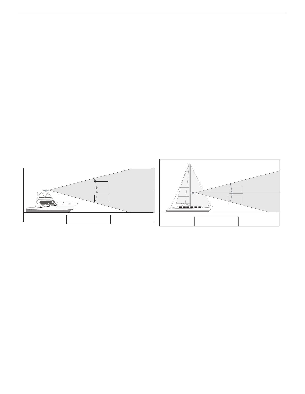
12.5°
12.5°
Ideal Radiation Plane
Ideal Radiation Plane
12.5°
12.5°
• Mount other electronics and cables more than 2 m (7 ft) from the path of a radar beam. A radar beam can normally be assumed to spread
25° vertically above and below the scanner’s radiating element. For vessel’s with higher bow angles at cruise speed, it may be helpful to
lower the angle so the beam points slightly downwards to the waterline while at rest. Shims may be used as necessary.
• Install the scanner away from antennas for other electronics. GPS antennas should be either above or below the radar beam path of the
scanner. Mount at least 1 m (3 ft) from any equipment transmitting or cables carrying radio signals e.g. VHF radios, cables and antennas.
In the case of SSB radios, the distance should be increased to 2 m (7 ft). IEC 60936-1 clause 3-27.1 maximum distances from the antenna
at which RF (Radio Frequency) levels can be expected.
GMR20 (100W/m squared = 40cm [15.75”]) (10W/m squared = 120cm [47.24”])
GMR40 (100W/m squared = 60cm [23.62”]) (10W/m squared = 175cm [68.90”])
• The radar scanner transmits electromagnetic energy. It is important that the radar is turned off and/or DC power input be disconnected
whenever personnel are required to come close to the scanner to perform work on the scanner assembly or associated equipment.
Installation
The following order of mounting the scanner and attaching the Power/Network cables may vary depending on the installation location and
mount used.
GMR 20/40 Radar Installation Manual
2
 Loading...