

Garmin APOLLO GX SERIES Service Manual

Service Manual
Apollo GX Series
Confidential, unpublished property of Garmin AT, Inc. Use and distribution is limited
solely to authorized personnel. The use, disclosure, reproduction, modific ation, t ransf er,
or transmittal of any portion of this work for any purpose in any form or by any means
without the express written permission of Garmin AT is strictly prohibited.
October 2004 560-7001-501 Rev. --

Garmin AT Rev. --
© 2004 Garmin Ltd. or its subsidiaries. All rights reserved. Printed in the U.S.A.
st
Garmin International, Inc., 1200 East 151
Street, Olathe Kansas 66062, U.S.A.
Tel: 913/397.8200 Fax: 913/397.8282
Garmin (Europe) Ltd., Unit 5, The Quadrangle, Abbey Park Industrial Estate, Romsey, Hampshire
S051 9DL, U.K.
Tel: 44.1794.519944 Fax: 44.1794.519222
Garmin Corporation, No. 68, Jangshu 2
nd
Road, Shijr, Taipei County, Taiwan
Tel: 886/02.2642.9199 Fax: 886.02.2642.9099
Garmin AT, Inc., 2345 Turner Road, S.E., Salem, OR 97302, U.S.A.
Tel: 800.525.6726 Fax: 503.364.2138
Canada Tel: 800.654.3415
International Tel: 503.391.3411
Visit our web pages at http://www.garmin.com
Send comments about this manual by email to: techpubs.salem@garmin.com
Except as expressly provided herein, no part of this manual may be reproduced, copied, transmitted,
disseminated, downloaded or stored in any storage medium, for any purpose without the express
written permission of Garmin. Garmin hereby grants permission to download a single copy of this
manual and of any revision to this manual onto a hard drive or other electronic storage medium to be
viewed for personal use, provided that such electronic or printed copy of this manual or revision must
contain the complete text of this copyright notice and provided further that any unauthorized
commercial distribution of this manual or any revision hereto is strictly prohibited.
Information in this document is subject to change without notice. Garmin reserves the right to change
or improve their products and to make changes in the content of this material without obligation to
notify any person or organization of such changes or improvements.
Garmin®, Garmin AT®, II Morrow, Apollo, and GNS are trademarks of Garmin Ltd. or its subsidiaries.
These trademarks may not be used without the express permission of Garmin.
ii GX Service Manual © 2004 Garmin AT

Garmin AT Rev. --
How to Contact Us
Telephone: 800-525-6726 US
800-654-3415 Canada
503-391-3411 International
Fax: 503-364-2138
Please feel free to fax us your orders (including account number, purchase order and shipping
method desired), literature requests, or service questions. If sending service questions, please
include serial number of unit, part number, software version, type and location of antenna, and as
much detail as possible about the problem.
E-mail Tech Support: techpubs.salem@garmin.com
If sending service questions, please include serial number of unit, part number, software version, type
and location of antenna, and as much detail as possible about the problem.
World Wide Web: www.garmin.com
Need an operation manual or install manual? How about a copy of an STC or flight manual
supplement? You can download most of our printed materials right off our website. This is a good
source of information for you and your customers. We have the latest information about our products.
It also allows end users to find dealers by doing a search in our nearest dealer listings. If you have
your own web site, you can link it to ours.
Navigating Our Phone System
When you call Garmin AT, the first thing you hear is, “Thank you for calling Garmin AT. Our business
hours are…” This is followed by a series of menu choices to help get you to the appropriate
department. Here are some department extensions to get you into our system without having to listen
to the menu choices:
If you need this: Call this extension:
Order Units 3990
Order Accessories 3990
Order Datacard and Field Upgrades 3995
Database Subscriptions 3995
Troubleshooting or Operational Questions 3991
Installation Questions 3991
Check repair status of a unit 3992
Billing or invoice questions 3994
Returning new products or special requests 3990
© 2004 Garmin AT GX Service Manual iii

Garmin AT Rev. --
TABLE OF CONTENTS
H
OW TO CONTACT US........................................................................................................................................III
LIST OF FIGURES ............................................................................................................................................... VI
HISTORY OF REVISIONS ....................................................................................................................................VII
HISTORY OF REVISIONS ....................................................................................................................................VII
CHAPTER 1. SERVICE REQUIREMENTS ............................................................................................................. 1-1
PRELIMINARY DATA........................................................................................................................................ 1-1
SERVICE AUTHORIZATION AND AUDITS ..........................................................................................................1-1
UPDATING SERVICE MANUALS........................................................................................................................ 1-1
ESD REQUIREMENTS....................................................................................................................................... 1-1
SOLDERING REQUIREMENTS............................................................................................................................ 1-1
SOURCES FOR SOLDERING STANDARDS........................................................................................................... 1-2
GPS SIGNAL SOURCE...................................................................................................................................... 1-2
TOOLS REQUIRED............................................................................................................................................ 1-2
GUIDE FOR USING HAND TOOLS....................................................................................................................... 1-2
GUIDE FOR USING FASTENERS ........................................................................................................................ 1-3
CHAPTER 2. INTRODUCTION.............................................................................................................................. 2-1
DISPLAY.......................................................................................................................................................... 2-2
EXTERNAL ANNUNCIATORS ............................................................................................................................ 2-2
CONTROLS....................................................................................................................................................... 2-2
KEYS ............................................................................................................................................................... 2-3
“SMART” KEYS ............................................................................................................................................... 2-3
MAP FUNCTION SMART KEYS ......................................................................................................................... 2-4
MAP WAYPOINT KEYS .................................................................................................................................... 2-4
APOLLO GX FEATURES................................................................................................................................... 2-6
CHAPTER 3. INSTALLATION MANUALS ............................................................................................................. 3-1
CHAPTER 4. ANTENNA INSTALLATION GUIDES................................................................................................ 4-1
CHAPTER 5. AIRCRAFT INSTALLATION TROUBLESHOOTING .......................................................................... 5-1
REDUCING THE EFFECTS OF VHF INTERFERENCE ON GPS INSTALLATIONS..................................................... 5-1
CHAPTER 6. THEORY OF OPERATION............................................................................................................... 6-1
NAV BOARD THEORY OF OPERATION............................................................................................................. 6-1
COMM THEORY OF OPERATION....................................................................................................................... 6-5
CHAPTER 7. RETURN TO SERVICE PROCEDURES ............................................................................................. 7-1
INTRODUCTION................................................................................................................................................ 7-1
PRELIMINARY DATA........................................................................................................................................ 7-4
FINAL TEST/INSPECTION ................................................................................................................................. 7-4
SETUP REQUIREMENTS.................................................................................................................................... 7-4
COMMON TESTS (ALL UNITS) ......................................................................................................................... 7-7
NAV RETURN TO SERVICE PROCEDURES........................................................................................................ 7-8
COMM RETURN TO SERVICE PROCEDURE...................................................................................................... 7-15
COMM TEST PROCEDURES.............................................................................................................................7-25
FINAL UNIT CHECKOUT................................................................................................................................. 7-55
CHAPTER 8. REPLACEMENT PROCEDURES....................................................................................................... 8-1
PURPOSE.......................................................................................................................................................... 8-1
PRELIMINARY DATA........................................................................................................................................ 8-1
BOARD LOCATIONS ......................................................................................................................................... 8-1
CHASSIS COVER REPLACEMENT...................................................................................................................... 8-4
iv GX Service Manual © 2004 Garmin AT

Garmin AT Rev. --
BATTERY REPLACEMENT .................................................................................................................................8-5
BEZEL ASSEMBLY REPLACEMENT....................................................................................................................8-6
CHASSIS REPLACEMENT...................................................................................................................................8-8
GX60/65 COMM BOARD FUSE REPLACEMENT.................................................................................................8-9
GX60/65 COMM BOARD REPLACEMENT........................................................................................................8-10
GX50 AND GX55 GPS BOARD REPLACEMENT..............................................................................................8-14
GX60 & GX65 GPS BOARD REPLACEMENT..................................................................................................8-15
KEYPAD REPLACEMENT.................................................................................................................................8-16
KNOB REPLACEMENT.....................................................................................................................................8-17
LENS REPLACEMENT......................................................................................................................................8-18
NAV BOARD FUSE REPLACEMENT ................................................................................................................8-19
NAV BOARD REPLACEMENT .........................................................................................................................8-20
SMART KEY REPLACEMENT ...........................................................................................................................8-21
NAV BOARD SOFTWARE UPGRADE ...............................................................................................................8-22
COMM BOARD SOFTWARE UPGRADE.............................................................................................................8-24
COMPLETE INITIALIZATION............................................................................................................................8-25
CHAPTER 9. TROUBLESHOOTING...................................................................................................................... 9-1
PRELIMINARY DATA.........................................................................................................................................9-1
ERROR MESSAGES............................................................................................................................................9-1
SYMPTOMS.......................................................................................................................................................9-3
EEPROM DATA...............................................................................................................................................9-7
CHAPTER 10. DRAWINGS................................................................................................................................. 10-1
COMPONENT LAYOUTS ..................................................................................................................................10-1
BLOCK DIAGRAMS .........................................................................................................................................10-9
ASSEMBLY DRAWINGS.................................................................................................................................10-18
CHAPTER 11. PARTS LISTS.............................................................................................................................. 11-1
COMMON PARTS.............................................................................................................................................11-1
GX50 PARTS ..................................................................................................................................................11-2
GX55 PARTS ..................................................................................................................................................11-2
GX60 PARTS ..................................................................................................................................................11-3
GX65 PARTS ..................................................................................................................................................11-4
DATA CARDS..................................................................................................................................................11-5
MAINTENANCE SUPPLIES ...............................................................................................................................11-5
CHAPTER 12. REGULATORY DOCUMENTS...................................................................................................... 12-1
CHAPTER 13. SERVICE DATA SHEET .............................................................................................................. 13-1
© 2004 Garmin AT GX Service Manual v

Garmin AT Rev. --
LIST OF FIGURES
F
IGURE 7-1. GX55 ASSEMBLY BOARD LOCATIONS ............................................................................................ 8-2
FIGURE 7-2. GX 50/60/65 ASSEMBLY BOARD LOCATIONS.................................................................................. 8-3
FIGURE 7-3. RIBBON CABLE PLACEMENT ON BEZEL ASSEMBLY AND NAV BOARD ........................................... 8-7
FIGURE 7-4. RIBBON CABLE PLACEMENT.......................................................................................................... 8-11
FIGURE 7-5. FLEX CIRCUIT PLACEMENT............................................................................................................ 8-21
FIGURE 9-1. GX55 NAV PCB COMPONENT LAYOUT (REFERENCE ONLY) (SHEET 1 OF 3)............................... 10-1
FIGURE 9-2. GX 50/60/65 NAV PCB COMPONENT LAYOUT (REFERENCE ONLY) (SHEET 1 OF 2).................... 10-4
FIGURE 9-3. COMM PCB COMPONENT LAYOUT (REFERENCE ONLY) (SHEET 1 OF 3) .......................................10-6
FIGURE 9-4. NAV BLOCK DIAGRAM .................................................................................................................10-9
FIGURE 9-5. COMM BOARD BLOCK DIAGRAM.................................................................................................10-10
FIGURE 9-6. VHF COMM MAIN PCA BLOCK DIAGRAM.................................................................................. 10-11
FIGURE 9-7. MICROCONTROLLER BLOCK DIAGRAM .......................................................................................10-12
FIGURE 9-8. VHF COMM SYNTHESIZER BLOCK DIAGRAM..............................................................................10-13
FIGURE 9-9. RECEIVER BLOCK DIAGRAM .......................................................................................................10-14
FIGURE 9-10. AUDIO CIRCUITS BLOCK DIAGRAM ........................................................................................... 10-15
FIGURE 9-11. VHF COMM TRANSMITTER BLOCK DIAGRAM........................................................................... 10-16
FIGURE 9-12. VHF COMM POWER SUPPLY/AUDIO AMP BLOCK DIAGRAM.....................................................10-17
FIGURE 9-13. GX55 ASSEMBLY (REFERENCE ONLY) (SHEET 1 OF 2).............................................................. 10-18
FIGURE 9-14. GX50, 60, 65 ASSEMBLY (REFERENCE ONLY) (SHEET 1 OF 2).................................................. 10-20
vi GX Service Manual © 2004 Garmin AT

Garmin AT Rev. --
History of Revisions
July 1999 ....................................................................................................................... Original Release
January 2001 ...........................................................................................................................Revision A
This revision incorporates changes in drawings due to previous ENs. Refer to EN6010,
EN6125, EN6320, EN6393, and EN6432.
October 2004 ...........................................................................................................................Revision --
Changed UPSAT to Garmin AT. Also deleted three chapters to make more web
friendly.
© 2004 Garmin AT GX Service Manual vii

Garmin AT Rev. --
This Page Intentionally Left Blank
viii GX Service Manual © 2004 Garmin AT

Chapter 1. Service Requirements
Preliminary Data
Prior to performing any repair or testing, fill out the appropriate fields of the Service Data Sheet. A
copy is located at the back of this manual. This will be used when service is completed to reenter
customer configuration and perform final test and inspection.
Service Authorization and Audits
Only UPS Aviation Technologies authorized Level II service centers can service UPS Aviation
Technologies avionics equipment. A level II service center must meet the following requirements:
• FAA or local civil aviation authority repair station certification in the radio and/or navigation
category.
• Completion of factory sponsored Level II training or passing a written test.
• Possession of the most current version of the maintenance manual and/or applicable USP
Aviation Technologies service literature.
• Fulfillment of the minimum test equipment requirements as listed in the maintenance manual,
including provisions for static control (ESD).
Contact UPS Aviation Technologies for more information.
Updating Service Manuals
It is required that all service centers have the latest revision of the service manuals prior to performing
any maintenance. The manual document numbers and configurations are available via the Internet or
by calling UPS Aviation Technologies at the numbers given in the front of this manual.
ESD Requirements
ESD precautions must be followed at all times when handling components or circuit boards. When
working on the unit, you must use a grounded wrist strap and a grounded working surface. Circuit
boards or components must only be carried in a nonconductive, anti-static bag. Reference EIA
Standard # EIA-625.
All components to be shipped require appropriate ESD protective packaging.
Soldering Requirements
Use a grounded tip, temperature controlled solder iron operating at 600 to 700 degrees Fahrenheit.
The solder, wick and flux are “no-clean” products. If others are used, the boards must be cleaned
after servicing to remove residues. See the parts list for these items. Reference the following
standards:
IPC-R-7721 and 7711 (or newer) Guidelines for Rework and Repair of Printed Boards and
Assemblies.
IPC-A-610A (or newer) Acceptability of Electronic Assemblies.
© 2004 Garmin AT GX Service Manual 1-1

Garmin AT Rev --
Sources for Soldering Standards
Electronic Industries Association
Engineering Dept.
2001 Pennsylvania Ave. N.W.
Washington, DC 20006
Also:
Global Engineering Documents
(800) 854-7179 (US & Canada)
(303) 397-7956 (International)
Institute for Interconnecting and Packing Electronic Circuits.
2125 Sanders Road
Northbrook, IL 60062
Tel (847) 509-9700
Fax (847) 509-9798
(www.ipc.org)
GPS Signal Source
A GPS signal source is required for Return to Service of the GPS Navigation units. See page 7-6.
Tools Required
• #1 Phillips screwdriver
• 5 lb.-in. torque wrench with #1 Phillips driver bit
• Needle nose pliers
• ¼" Nut driver
• 0.312" Nut driver
• Solder iron - grounded tip, temperature controlled (600-700 degrees F)
• Solder wick - “no clean,” Tech Spray p/n 1815-100F (0.060" dia) or 1816-100F (0.85" dia) or
equivalent
• Solder - “no clean,” Qualitek p/n NC600 (63/37), or equivalent
• Flux – “no clean,” Qualitek p/n 302 No-Clean flux or p/n rwrk wand, no-clean
• Slotted screwdriver
• 0.050 Hex driver
• Glass cleaner, non-ammonia base
• Cleaning wipes – low lint
• Integrated circuit puller
Guide for using hand tools
1. Always use the appropriate size tool.
2. Exterior and interior screws should be tightened only with a torque screwdriver set to the
specified torque. Refer to the instruction manual supplied with the torque screwdriver. The correct
tightening torque is shown in each procedure.
1-2 GX Service Manual © 2004 Garmin AT

Garmin AT Rev --
Guide for Using Fasteners
1. Make sure that you use the proper screw in each location. Note the difference between
countersunk and undercut screws. Use appropriate screws.
2. Be careful not to damage screws. Screws with damaged threads or stripped heads must be
discarded and replaced with the appropriate screws.
© 2004 Garmin AT GX Service Manual 1-3

Garmin AT Rev --
1-4 GX Service Manual © 2004 Garmin AT
Chapter 2. Introduction
This guide describes the maintenance of the Apollo GX line of products. The GX50 and GX55 are
GPS receivers. The GX60/65 models combine the GPS receiver with a VHF radio in a single
package.
The Apollo GX products are high-performance GPS products with a high-resolution moving map
display configured in a 2-inch high by 6.25-inch wide standard package. The Apollo GX’s use a
powerful, accurate 8-channel GPS engine designed specifically for high-performance aviation use.
The 160 by 80 pixel electroluminescent display uses an automatic intensity control to keep it easily
readable in all conditions from direct sunlight to the dark of night.
A wealth of easy to use features serves the needs of today’s demanding aviation requirements. The
large waypoint database has information about airports, VORs, NDBs, intersections, and special use
airspaces that makes the Apollo GX an encyclopedia of aviation. It’s what you’d expect from UPS
Aviation Technologies the first to provide a database in a general aviation navigation aid. The
database can be updated by simply changing the removable data card in the front of the unit. The
database can also include 500 custom waypoints created by the user. Thirty flight plans can be saved
with up to twenty legs for setting up custom tailored routes. The detailed navigation information
displays are also customizable and can be set to automatically scroll through the desired information.
The Nearest/Emergency Search feature, invented by UPS Aviation Technologies, makes it easy to
react to an emergency or change your active flight plan.
GX55
The GX55 is designed to be a simple slide-in replacement for panel-mounted Apollo Loran and
Flybuddy GPS receivers. The GX55 connectors and antenna footprint are the same as the Apollo
Loran and Flybuddy GPS receivers. The GX55 is TSO-C129 Class A2 authorized for IFR en route
and terminal operation.
© 2004 Garmin AT GX Service Manual 2-1

Garmin AT Rev --
GX50
The Apollo GX50 GPS receiver possesses all of the performance features of the GX55, plus more.
The GX50 is TSO-C129a Class A1 authorized for IFR nonprecision approach operation. The GX50
uses the same tray size, but different connections on the back to allow for approach capabilities.
GX60
The Apollo GX60 combines the physical package of the GX50 GPS receiver with a revolutionary VHF
Comm transceiver. All of this without the requirement for external cooling.
GX65
The Apollo GX65 possesses the same features as the GX60, except it is not certified for IFR
approaches.
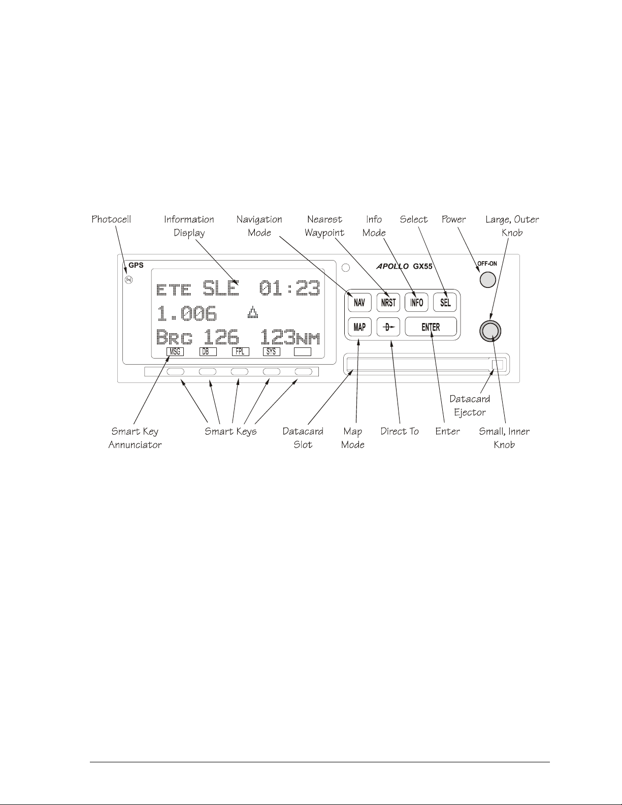
Display
The display is a 160 by 80 pixel electroluminescent graphic display. A photocell is located in the top
left corner of the front panel display. The photocell automatically controls the light intensity of the
display from low brightness at night to high brightness during daylight operation.
External Annunciators
When external indicators are installed, the Apollo GX will also provide an external indication when
Parallel Track (PTK) is activated or a Message (MSG) is received. The GX50/60 also have external
annunciator controls for OBS/Hold and Approach Active.
Controls
The Apollo GX uses a variety of controls to manage the features. The controls include a power knob,
dual-concentric knobs (called large and small), hard keys, and “smart” keys.
Power Knob
The knob on the top right side of the Apollo GX controls power on/off. Rotate the knob clockwise
(CW) past the detent to turn the power on. Rotate the knob fully counterclockwise to turn the power
off. Full rotation and the push-pull capabilities are only used in the GX60/65.
Power/Volume/Squelch Knob (GX60/65)
The knob on the right side of the GX60/65 controls power on/off, volume, and squelch test. Rotate the
knob clockwise (CW) past the detent to turn the power on. Continue rotating the knob to the right to
increase speaker and headphone amplifier volume level. Rotate the knob to the left to reduce the
volume level. Pull the knob out to disable automatic squelch.
2-2 GX Service Manual © 2004 Garmin AT
The dual concentric knobs on the right side of the front panel are used to select pages, edit
characters and values, or other options. The large knob moves the cursor and the small knob
changes characters. Either may change pages depending on the function.
Small and Large Knobs
Garmin AT Rev --
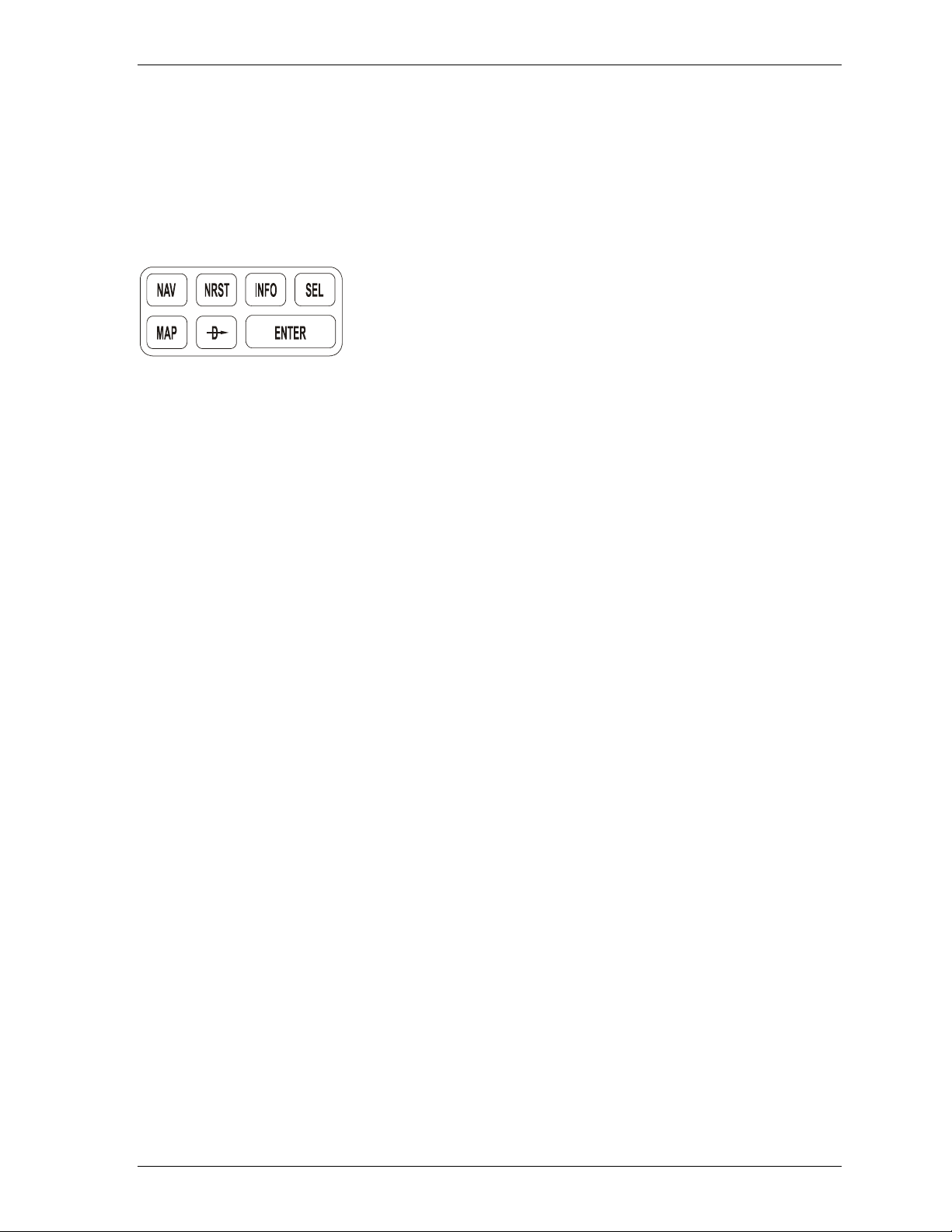
Keys
There are two types of keys that allow you access to the functions in your Apollo GX: permanent
“hard” keys and displayed “smart” keys. Seven backlighted permanent keys are used to reach the
functions or perform other operations of the Apollo GX. The “smart” key labels are shown on the
bottom of the display. There are two categories of “smart” keys: those available for the Map function
and those available at all other times. Press the key below the label to use the displayed function.
Press a function key once to go to the last page viewed or twice to go to its “home” page.
Hard Keys
The “hard” keys are the easy-touch, black, rounded keys with white
lettering on the right side of the display. These keys include, NAV,
NRST, INFO, SEL, MAP, Direct-To, and ENTER.
NAV (Navigation)
Press the NAV key to reach the navigation functions. Press twice to go to the “top” page.
NRST (Nearest Waypoint)
The Nearest Waypoint (Emergency) mode displays the closest waypoints to your position.
INFO (Information)
The Info function accesses supplementary information about a waypoint. Press INFO a second time
to return to the previous display.
SEL (Select)
The SELECT key activates editing or the selection of options. Editing is active on the items that flash
on the display. Press SEL a second time to deactivate selection.
MAP (Graphic Moving Map)
The MAP key starts the moving map function. The entire display is used as a graphic map display.
DIRECT-TO
The Direct-To key is used to define a direct course from your present position to a waypoint. Press
once to select a waypoint. Press twice to enter an OBS desired track To or From the current active
waypoint.
ENTER
The ENTER key enters and saves the information flashing on the display. If the ENTER key is not
pressed after editing, any changes made are not saved. In the GX60/65, the ENTER key flip/flops the
Active and Standby frequencies.
“Smart” Keys
The Apollo GX uses “smart” keys to provide custom controls for specialized functions. Five small,
unlabeled keys are located below the display. The labels appear on the display and can change to
give extra controls for the active function, such as in the MAP function. You can always press the
NAV key to go back to the navigation function and view the normal “smart” keys.
© 2004 Garmin AT GX Service Manual 2-3

Garmin AT Rev --
MSG (Message)
Press the MSG key to reach the message functions. The MSG annunciator will flash when a new
message is provided. Press the MSG key a second time to return to the previous display after all new
messages have been viewed. The MSG key will remain highlighted when a message remains.
DB (Database)
The database key provides access to the waypoint database.
FPL (Flight Plan)
The flight plan key takes you to the flight planning function where you can create, edit, and control
your flight plans.
SYS (System Mode)
Press the SYS key to reach the system mode functions. System mode is used to make system level
adjustments and modify navigation function displays.
SKIP (Start-Up Option)
Press the SKIP key during the start-up procedure to bypass the start-up tests. This is for
emergencies, as the IFR tests must be completed to allow IFR flight.
Map Function Smart Keys
The moving map function uses several “smart” keys to allow you to declutter the map, find waypoint
information, and setup your map information.
Map Waypoint Keys
APT, VOR, INT, NDB, & USR
The map waypoint “smart” keys are present when the Moving Map pages are displayed. Press the
“smart” key to control the display of the waypoint type. There are three selections possible: waypoint
identifier and location symbol, location symbol only, and off. Pressing the “smart” key subsequent
times will control which selection is made. Map waypoint choices are Airport (APT), VOR, NDB,
Intersection (INT), and User (USR).
A solid, reversed waypoint-type annunciator above the “smart” key means the waypoint identifier and
location symbol will both be displayed.
A bold outline of the waypoint type annunciator will show only a symbol on the waypoint location.
A thin outline around the waypoint type means that it is turned off and no information for that waypoint
type will be displayed on the map.
Waypoint LIST Key
Each press of this key scrolls through the available “smart” keys.
Waypoint SCAN Key
When the SCAN key is active (highlighted) in the moving map display, turning the large knob will
move between the nearest airports. You can then press INFO to view information about that airport.
2-4 GX Service Manual © 2004 Garmin AT

Garmin AT Rev --
In an emergency, press DIRECT-TO and ENTER to fly direct to the highlighted airport. Press the
SCAN key again to return the large knob to normal operation.
Map Setup Keys
The Map Setup page displays three “smart” keys that provide a short cut for customizing your moving
map.
The Route Line “smart” key toggles between On and Off.
The Map Orientation “smart” key toggles between Desired Track (DTK), Track, and North.
The Map Reference “smart” key toggles between Plane and Destination (Dest) as the moving map
center point.
Communications Radio Mode Smart Keys - GX60/65
The Recall (RCL), Monitor (MON), Memorize (MEM), and Flip/Flop (↔) keys are available in the
GX60/65 after the COM soft key has been pressed.
COM (GX60/65)
Press the COM key to operate the communications radio functions.
Flip/Flop (GX60/65)
Press the Flip/Flop key to switch between the active (left-most) and standby (right-most) frequency
while in the Comm function. You may use an optional external Flip/Flop key for the same operation as
the front panel control. Switching between frequencies is disabled while you are transmitting or
editing in any function.
RCL (Recall) (GX60/65)
Press the RCL key to recall frequencies stored in the database.
MON (Monitor) (GX60/65)
Press the MON key to listen to the standby frequency. When the active frequency receives a signal,
the GX60 will automatically switch to the active frequency.
MEM (Memorize) (GX60/65 )
Press the MEM key to store the current standby frequency.
XIT (Exit) (GX60/65)
The XIT key will appear on the far left of the display, in the MSG key position, if the COM key has
been pressed to allow use of the radio during startup testing. Press the XIT key to return to the startup sequence, or wait for test completion. The XIT key will disappear when testing is complete.
© 2004 Garmin AT GX Service Manual 2-5

Garmin AT Rev --
Apollo GX Features
Navigation Features
• High resolution, daylight-readable graphics display
• Automatic display intensity
• Back-lit buttons
• Simple “Direct-To” navigation
• Datacard database for easy user update and replacement
• Nearest waypoint and airspace search (includes airports, VORs, NDBs, intersections, and
user waypoints)
• Remote waypoint search
• Navigation displays -
− Lat/Lon to 0.01 minute
− Bearing and distance to waypoint
− Ground speed and track angle
− Track angle error
− Desired track and distance between waypoints
− Cross track error with numeric and graphic CDI
− Display of the “TO” waypoint ident
− ETE and ETA to the “TO” and destination waypoints
− Altitude (from altitude encoder/converter input)
− Minimum safe altitude and en route safe altitude information
• Map Displays -
− Full screen map with bearing, distance to waypoint, and zoom level
− Split screen map with distance, speed, bearing, track, crosstrack error, To waypoint, and
zoom level
− Split screen with navigation data and communication frequency display (GX60/65 only)
− Smart key, 1 button map declutter, Tri-state
− On map waypoint selection for information, direct-to nomination
− Track up, desired track up, and magnetic north up options
− Runway diagrams and runway names displayed
− 5 nm ATC rings around airports with control towers
− Airspaces displayed by sector or outer boundary
− Airspace display controllable by type
− Approach preview page (GX50/60 only)
− Route line displayed
2-6 GX Service Manual © 2004 Garmin AT

Garmin AT Rev --
• Automatic waypoint sequencing
• Vectors to final input (GX50/60 only)
• DME arc assist
• Built-in simulator for trip planning and training
• User definable navigation pages with auto sequencing
• 30 reversible flight plans of up to 20 legs with automatic sequencing
• 500 user waypoints created by lat/lon or by radial/distance from a reference waypoint
• Real time clock (time and date) in UTC
• Countdown timer
• Flight timer
• Automatic or manual magnetic variation
• Parallel track offset
• Alerts for -
− Loss of navigation data
− Arrival at waypoint
− Special use airspace
• Full range (10 VDC to 40 VDC) input supply voltage
GPS Receiver Performance Specifications
• 8-channel parallel GPS receiver
− Frequency: 1575.42 MHz L1, C/A code
• Sensitivity (acquisition): -135 dBm
• Sensitivity (drop lock): -142 dBm
• Dynamic range: >20 dB
• Lat/Lon position accuracy
− 15 meters RMS accuracy
− 25 meters, SEP, without SA
− 100 meters 2 DRMS with SA
• Velocity: 999 knots maximum
− Acceleration: 4G maximum
• TTFF (time to first fix)
• 25 sec. (typical) with current almanac, position, time, and ephemeris
• 55 seconds typical with current almanac, position, & time
• Reacquisition: 2.5 seconds typical
• Position update interval: 1 second typical
• Datum: WGS-84
© 2004 Garmin AT GX Service Manual 2-7

Garmin AT Rev --
Electrical
• Input voltage
− 10 VDC to 40 VDC, reverse polarity protected
• Input current (GPS navigation input)
− 500 mA typical, 750 mA max at 13.75 VDC
− 250 mA typical, 375 mA max at 27.5 VDC
• Input current (communication input - GX60/65 only)
− 270 mA typical, 2 A max at 13.75 VDC, receive
− 130 mA typical, 900 mA max at 27.5 VDC, receive
− 2.1A typical, 3.2 A max at 13.75, transmit
− 1.0A typical, 1.4 A max at 27.5 VDC, transmit
• Input power (GPS navigation input)
− 7 watts typical
• Input power (communication input - GX60/65 only)
− 3.7 watts typical, receive
− 28 watts typical, transmit
GX50 and GX60/65 Avionics Outputs
• CDI L/R deviation ± 150 mV full scale
• TO/OFF/FROM flag ± 250 mV, TO/FROM indication
• Navigation valid flag +300 mV for valid indication
• Navigation superflag 400 mA source
• VDI up/down ± 150 mV
• VDI valid flag +300 mV
• VDI superflag 400 mA source
• Annunciators
− MSG (message)
− PTK (parallel track)
− OBS/HLD (waypoint sequencing hold) GX50/60 only
− APPRCH (approach enabled) GX50/ 60 only
− ACTIVE (approach active) GX50/60 only
2-8 GX Service Manual © 2004 Garmin AT

Garmin AT Rev --
GX55 Avionics Outputs
• CDI L/R deviation ± 150 mV full scale
• TO/OFF/FROM flag ± 250 mV TO/FROM indication
• Navigation valid flag +300 mV for valid indication
• Annunciators
− MSG (message)
− PTK (parallel track)
Avionics Inputs
• Serial
• Frequency flip/flop (GX60/65 only)
• Waypoint Sequence (GX50/60 only)
Serial Interface
• 2 RS-232 for GX50/60/65
• 1 RS-232 for GX55
Physical Specifications
• Height: 2.0 inches (5.08 cm)
• Width: 6.25 inches (15.88 cm)
• Depth: 11.125 inches (28.26 cm) behind panel, including mounting frame and connectors
• Weight (with mounting frame):
− GX50 and GX55 - 2.6 pounds (1.179 kg)
− GX60/65 - 3.1 pounds (1.409 kg)
Environmental Specifications
• Operating temperature -20º C to +55º C
• Storage temperature -55º C to +85º C
• Temperature variation 2º C per minute
• Humidity 95% at 50º C for 6 hrs (2 day cycle)
• Maximum altitude 55,000 feet
• Cooling Not required
© 2004 Garmin AT GX Service Manual 2-9

Garmin AT Rev --
VHF Comm Features (GX60/65)
• 760 channels
• Frequency range of 118.000 to 136.975 MHz
• Active and standby frequency display
• Transmit status indicator
• Stuck mic time-out
• Frequency monitor function - listen to standby frequency while monitoring active frequency
for any activity
• Weather channels - National Weather Service channels
• Built-in intercom function
• Frequency memory and recall functions
− From navigation data base
− Ten last used
− Ten user stored
• Two microphone inputs
• 12 watt audio amplifier
VHF Comm Receiver Performance Specifications (GX60/65)
• Class D
• Frequency range - 118.000 to 136.975 MHz, 760 channels
• Sensitivity
− 1 microvolt (2 microvolt hard) for 6 dB S+N/N
− 30% modulation at 1000 Hz
• Selectivity
− <6 dB variation at ± 22 kHz
• Speaker audio output level
− 12 watts into 4 ohms, 8 watts into 8 ohms
• Headphone audio output level
− 280 mW into 100 ohms, 120 mW into 500 ohms
• Distortion - <5% at rated output at 1000 Hz
• AGC characteristics
− <3 dB variation in audio output from 5 to 100 mV input
− 15% to 90% modulation
• Squelch control - automatic with manual override
2-10 GX Service Manual © 2004 Garmin AT

Garmin AT Rev --
VHF Comm Transceiver Performance Specifications (GX60/65)
• Class 4
• Output power
− 8 watts minimum carrier at >12 VDC
− 6 watts minimum at 10 VDC (transmit is locked out below 9 VDC input)
• Modulation capability
− 85% with 100 mv to 1000 mv rms microphone input at 1000 Hz
• Duty cycle 100%
• Stuck mic time out
− 35-second time-out, reverts to receive
TSO Authorizations
• GX50
− TSO C129A A1
• GX55
− TSO C129 A2
• GX60
− TSO C129A A1
− TSO C128
− TSO C37d
− TSO C38d
• GX65
− TSO C129A A2
− TSO C128
− TSO C37d
− TSO C38d
Features and specifications subject to change without notice.
© 2004 Garmin AT GX Service Manual 2-11

Garmin AT Rev --
2-12 GX Service Manual © 2004 Garmin AT

Chapter 3. Installation Manuals
Please refer to the Dealer’s Only website at http://www.garmin.com to download the latest installation
manuals.
© 2004 Garmin AT GX Service Manual 3-1

Garmin AT Rev --
3-2 GX Service Manual © 2004 Garmin AT

Chapter 4. Antenna Installation Guides
© 2004 Garmin AT GX Service Manual 4-1

Garmin AT Rev --
4-2 GX Service Manual © 2004 Garmin AT

Chapter 5. Aircraft Installation Troubleshooting
Reducing the effects of VHF Interference on GPS Installations
Why do we test for VHF interference?
Checking for VHF harmonic interference is a requirement called out in the FAA Advisory Circular AC
20-138. The Advisory Circular requires VHF interference checks along with other requirements
needed to gain approval. The GPS signals are transmitted from satellites that are in orbit 10,000
miles above the earth. By the time these signals reach the earth they are weak, buried in noise, and
easily swamped by an interference source. As GPS receivers are susceptible to VHF harmonics and
other interference on the L1 GPS frequency, all GPS receivers approved for use in instrument
conditions must have the VHF interference tests performed.
There are new FAA changes to AC 20-138 that will expose more VHF interference problems than you
have experienced in the past. These changes will require the shops to test each interfering frequency
for a period of 45 seconds. The current requirement calls for a 20-second transmit test. The changes
are intended to identify all interference sources to insure reliable GPS performance in IFR conditions.
Some GPS manufactures have masked VHF interference problems through software techniques like
coasting, and not warning the pilot during temporary signal outages. Coasting is a method for dealing
with momentary outages, but the TSO also requires the GPS receiver to warn pilots within 10
seconds of a signal loss during approach operations. All UPS Aviation Technologies GPS products
will warn the pilot within 10 seconds per the TSO requirements. It is important to isolate potential VHF
interference sources, and eliminate them.
The Advisory Circular states, “Remove any source of VHF interference from the aircraft.” We have
listed some steps that can be taken to reduce the effects of interference. The intent here is to save
you time and money on GPS installations. The following provides some practical steps to help you
identify and minimize GPS interference sources on board aircraft.
What can we do to minimize VHF interference?
Perform a pre-installation check to determine if there is going to be a problem with VHF interference.
Ninety percent of the time when our tech support phone rings with one of these VHF problems, we
hear, “The equipment is installed, antenna bolted down. I’ve tried everything. Can you help?” We
recommend that you perform a pre-installation checkout that will help determine if there is a VHF
interference problem.
Pre-Installation Checkout
Take a few minutes with the aircraft before completing the installation quote to your customer. You
can get a good idea if you need to add a few extra hours to the quote by using a handheld GPS, or,
better yet, a spectrum analyzer. A spectrum analyzer is the preferred tool, if available. When using a
portable GPS, which is available to most shops, turn it on and observe the signal strength display. For
example, the Apollo Precedus shows signal strength for up to eight satellites. Obtain some average
GPS signal strength readings as you walk around the aircraft. Key up Comm 1 on the entire list of
VHF frequencies listed in the Advisory Circular. Observe the effects of VHF transmissions on the
signal strength display of the portable GPS unit. Repeat the test for Comm 2. During the interference
checks, make sure you get the portable GPS antenna as close as you can to the VHF Comm
antennas, the ELT antenna, and the direction-finding antenna. This procedure should also help in
determining the best location for the GPS antenna. Check the interference levels at different topmounted locations using the portable GPS antenna. If the interference is too strong, causing a loss of
GPS signals in all possible antenna locations, follow the suppression guidelines below. You should
© 2004 Garmin AT GX Service Manual 5-1

Garmin AT Rev --
also include extra time in installation quotes to allow time to identify and isolate the interference
source(s).
What are the sources of VHF interference?
The main sources of VHF interference fall into one of the categories listed below.
th
1. VHF harmonic interference broadcast on the 12
frequency by Comm and NAV/Comm transceivers.
2. A clean VHF signal can produce interference when it is picked up by an ELT antenna. Non-linear
components in the ELT antenna generate interfering harmonics which are re-broadcast and
interfere with the GPS.
3. A clean VHF signal can produce interference when it is picked up by a direction finding antenna
(used mainly in search and rescue aircraft). Non-linear components in the antenna system or
front end generate harmonics which are re-radiated from the direction finding antenna.
4. VHF harmonic interference emitted from the NAV/Comm radio case and front panel.
5. Inter-coupling between multiple Comms and NAV/Comms. Usually, both Comm antennas are
mounted on the top side in close proximity. In these cases, we’ve seen the Comm 1 transmitter
couple to the Comm 2 receiver or vice versa causing the re-broadcast of L1 interference through
the case and display of Comm 2. For example, let’s say a GPS/Comm is designated as Comm 1
and a NAV/Comm is designated as Comm 2. When the Comm 1 transmitter is keyed on one of
the interfering VHF frequencies, the RF transmit energy is coupled to the Comm 2 receiver and
interference on the L1 GPS frequency can be re-emitted from the case and display of Comm 2.
and/or 13th harmonic of the fundamental VHF
More than one of these VHF interference problems can occur on the same aircraft at the same time.
The real problem is being able to identify and isolate the interference.
Isolating the sources of VHF Interference
The following steps are to be taken only if you have verified L1 interference during the pre-installation
checkout. Install the GPS unit in the panel according to the manufacturer’s instructions. Run the
antenna coax (RG-142B) and leave some extra lead length, but do no mount the antenna. We
suggest you make up a test coax harness for use during GPS installations. Using the test coax
harness, connect it to the GPS antenna on top as close to the desired location as possible.
Remove Comm 2 and the ELT from the aircraft. Test Comm 1 on all the known interfering
frequencies listed in the AC or the Apollo Installation manual.
If there is GPS signal degradation, re-test Comm 1 on a dummy load to determine if the VHF
harmonic interference is being transmitted out the antenna or radiated from the NAV/Comm unit. If
the VHF interference occurs only during transmitting, install a GPS notch filter in line with the
antenna. The GPS notch filters will attenuate the interference by 40 dB, which will suppress the 12
and 13
th
harmonic interference.
If the problem exists only under dummy load, then the interference is radiating from the case and
front panel of Comm 2. Try to re-position the GPS antenna to minimize the effects of the interference.
Additional shielding around the case of the NAV/Comm has been effective in suppressing
interference. Wrap the entire unit in aluminum foil for testing. A metal case with appropriate grounding
may be needed as a permanent fix.
We have experienced interference on a number of installations involving an existing GPS receiver.
Try installing GPS filters and/or appropriate metal shielding, such as 0.020" aluminum, around the
case to suppress the L1 interference. The L1 interference on the GPS receiver emits from the sheet
metal seams in the case. It is important to completely enclose the GPS receiver chassis in
appropriate metal shielding. We have also seen some extreme cases where the interference emits
from the front panel and display area of the GPS receiver. Re-positioning the antenna can usually
correct the problem. If not contact the manufacturer of the GPS receiver for additional help. It’s
th
5-2 GX Service Manual © 2004 Garmin AT
 Loading...