

Garmin Apollo GX50 GPS, Apollo GX60 GPS, Apollo GX60 Comm, Apollo GX65 GPS, Apollo GX65 Comm Installation Manual

®
Apollo
Model GX50 GPS
Model GX60 GPS/Comm
Model GX65 GPS/Comm
Installation Manual
September 2003 560-0959-04b

© 2003 Garmin Ltd. or its subsidiaries. All rights reserved. Printed in the U.S.A.
Garmin International, Inc., 1200 East 151st Street, Olathe Kansas 66062, U.S.A.
Tel: 913/397.8200 Fax: 913/397.8282
Garmin (Europe) Ltd., Unit 5, The Quadrangle, Abbey Park Industrial Estate, Romsey,
Hampshire S051 9DL, U.K.
Tel: 44/1794.519944 Fax: 44/1794.519222
Garmin Corporation, No. 68, Jangshu 2nd Road, Shijr, Taipei County, Taiwan
Tel: 886/02.2642.9199 Fax: 886/02.2642.9099
Garmin AT, Inc., 2345 Turner Road, S.E., Salem, OR 97302, U.S.A.
Tel: 800/525.6726 Fax: 503/364.2138
Canada Tel: 800/654.3415
International Tel: 503/391.3411
Visit our web pages at http://www.garminat.com and http://www.garmin.com
Send comments about this manual by email to: techpubs.salem@garmin.com
Except as expressly provided herein, no part of this manual may be reproduced, copied,
transmitted, disseminated, downloaded or stored in any storage medium, for any purpose without
the express written permission of Garmin. Garmin hereby grants permission to download a single
copy of this manual and of any revision to this manual onto a hard drive or other electronic
storage medium to be viewed for personal use, provided that such electronic or printed copy of
this manual or revision must contain the complete text of this copyright notice and provided
further that any unauthorized commercial distribution of this manual or any revision hereto is
strictly prohibited.
Information in this document is subject to change without notice. Garmin reserves the right to
change or improve their products and to make changes in the content of this material without
obligation to notify any person or organization of such changes or improvements.
Garmin®, Garmin AT®, Garmin AT, Apollo, and GNS are trademarks of Garmin Ltd. or its
subsidiaries. These trademarks may not be used without the express permission of Garmin.

HISTORY OF REVISIONS
Revision SW Ver Date Description
-- Nov 5, 1997 Initial release.
-01 Nov 11, 1997 Corrected altitude input requirements.
-01b June 10, 1998 Added references about altitude encoders, F/AD, & serial
interface
-02 June 26, 1998 Addition of Model GX65 GPS/Comm
-03 Mar 24, 1999 Test Mode additions, Serial data output, Apollo ACU added
-03a Sept. 23, 1999 Added new connector pins and crimping tools
-03b 5/8/00 Add new extended data and SL30 output messages
-03c 3.3 7/2/01 Add autopilot roll steering data, and changes for GX SW
Ver 3.3. Mounting tube changes.
-04 2/18/02 Added helicopter environmental qualification information
-04a 3.5 4/2/02 Added Transceiver Status data output
-04b 9/18/03 Company name change
IMPORTANT NOTE
“The conditions and tests required for TSO approval of this article are minimum performance
standards. It is the responsibility of those desiring to install this article on or within a specific
type or class of aircraft to determine that the aircraft operating conditions are within TSO
standards. The article may be installed only if further evaluation by the applicant documents
an acceptable installation and is approved by the Administrator.”
Source: FAA TSO-C129a, TSO-C37d, TSO-C38d, and TSO-C128
ORDERING INFORMATION
To receive additional copies of this publication, order part # 560-0959-04b, Apollo GX50 GPS
and GX60/GX65 GPS/Comm Installation Manual.

NOTES

Table of Contents
TABLE OF CONTENTS
SECTION 1 - INTRODUCTION ................................................................................................ 1
ABOUT THIS MANUAL...................................................................................................................... 1
APOLLO GX50/60/65 DESCRIPTION ................................................................................................. 1
FEATURES ........................................................................................................................................ 3
SYSTEM CONFIGURATIONS ............................................................................................................... 4
VFR GPS NAVIGATION INSTALLATION ..................................................................................................................... 4
IFR GPS NAVIGATION INSTALLATION....................................................................................................................... 5
COMM TRANSCEIVER - GX60/65 .............................................................................................................................. 5
DATABASE UPDATES........................................................................................................................ 5
REGULATORY COMPLIANCE ............................................................................................................. 6
UNPACKING THE EQUIPMENT ........................................................................................................... 6
ACKAGE CONTENTS........................................................................................................................ 6
P
O
THER REQUIRED MATERIALS ......................................................................................................... 8
SPECIAL TOOLS REQUIRED............................................................................................................... 8
LICENSE REQUIREMENTS.................................................................................................................. 8
SECTION 2 - INSTALLATION.................................................................................................. 9
PRE-INSTALLATION INFORMATION ................................................................................................... 9
INSTALLATION OVERVIEW................................................................................................................ 9
INSTALLATION CONSIDERATIONS ..................................................................................................... 9
MOUNTING CONSIDERATIONS ................................................................................................................................... 9
MINIMUM SYSTEM CONFIGURATION ......................................................................................................................... 9
ALTITUDE INPUT ....................................................................................................................................................... 9
HELICOPTER REQUIREMENTS .................................................................................................................................. 10
EQUIPMENT MOUNTING ................................................................................................................. 10
MOUNTING TUBE INSTALLATION............................................................................................................................. 11
UNIT INSERTION ...................................................................................................................................................... 12
UNIT REMOVAL....................................................................................................................................................... 12
ELECTRICAL CONNECTIONS............................................................................................................ 14
POWER .................................................................................................................................................................... 14
AVIONICS OUTPUTS................................................................................................................................................. 14
SERIAL INTERFACE.................................................................................................................................................. 14
SPEAKER AND HEADPHONE OUTPUTS (GX60/65 ONLY) ......................................................................................... 15
MICROPHONE INPUTS (GX60/65 ONLY) .................................................................................................................. 15
TRANSMIT KEY INPUT (GX60/65 ONLY)................................................................................................................. 15
INTERCOM SELECTOR SWITCH (GX60/65 ONLY) .................................................................................................... 15
REMOTE FLIP/FLOP INPUT (GX60/65 ONLY) ........................................................................................................... 15
ANTENNA INSTALLATION AND CONNECTIONS ................................................................................ 15
COMM ANTENNA (GX60/65 ONLY) ........................................................................................................................ 15
GPS ANTENNA........................................................................................................................................................ 16
POST INSTALLATION CHECKOUT .................................................................................................... 25
TEST MODE CHECKOUT AND SETUP........................................................................................................................ 25
GPS NAVIGATION CHECKOUT................................................................................................................................. 27
VHF COMM CHECKOUT (GX60/65)........................................................................................................................ 28
FINAL SYSTEM CHECK............................................................................................................................................ 29
INTERFACE CHECKS ................................................................................................................................................ 29
SECTION 3 - SPECIFICATIONS ............................................................................................ 33
Apollo GX50/60/65 Installation Manual
i

Table of Contents
ELECTRICAL....................................................................................................................................33
PHYSICAL .......................................................................................................................................33
ENVIRONMENTAL............................................................................................................................34
GPS RECEIVER PERFORMANCE.......................................................................................................34
AVIONICS OUTPUTS ........................................................................................................................35
ALTITUDE INPUT REQUIREMENTS ...................................................................................................36
ANNUNCIATOR REQUIREMENTS ......................................................................................................36
COMM RECEIVER PERFORMANCE (GX60/65 ONLY)........................................................................37
COMM TRANSMITTER PERFORMANCE (GX60/65 ONLY) .................................................................37
INTERCOM PERFORMANCE (GX60/65 ONLY) ..................................................................................38
CONTROL INPUTS ............................................................................................................................38
ANTENNA REQUIREMENTS ..............................................................................................................38
GPS ANTENNA ........................................................................................................................................................38
COMM ANTENNA .....................................................................................................................................................38
SERIAL INTERFACE..........................................................................................................................38
REAR CONNECTOR PINOUT .............................................................................................................39
SECTION 4 - LIMITATIONS ...................................................................................................41
INSTALLATION ................................................................................................................................41
OPERATIONAL.................................................................................................................................41
APPENDIX A - TROUBLESHOOTING ..................................................................................43
CONTACTING THE FACTORY FOR ASSISTANCE ................................................................................44
APPENDIX B - PERIODIC MAINTENANCE ........................................................................45
LITHIUM BATTERY REPLACEMENT..................................................................................................45
EQUIPMENT CALIBRATION ..............................................................................................................45
REFERENCE OSCILLATOR (GX60/65) ......................................................................................................................45
CLEANING THE FRONT PANEL .........................................................................................................45
APPENDIX C - ENVIRONMENTAL QUALIFICATIONS...................................................47
APPENDIX D - ACCESSORIES ...............................................................................................49
FROM GARMIN AT..........................................................................................................................49
COMMERCIALLY AVAILABLE ..........................................................................................................52
APPENDIX E - SERIAL INTERFACE SPECIFICATIONS .................................................55
MOVING MAP OUTPUT ...................................................................................................................56
BINARY NEAREST LIST DATA (WHEN EXTENDED DATA IS ENABLED ONLY) ..................................59
ANNUNCIATOR OUTPUTS (WHEN EXTENDED DATA IS ENABLED ONLY) .........................................60
FLIGHT PLAN WAYPOINT TYPES (WHEN EXTENDED DATA IS ENABLED ONLY) ..............................61
NAVCOMM DATA OUTPUT .............................................................................................................62
REMOTE LOCALIZER LIST ........................................................................................................................................ 64
DISTANCE/SPEED/TIME MESSAGE ..................................................................................................66
ALTITUDE ENCODER/CONVERTER INPUT ........................................................................................67
FUEL/AIR DATA COMPUTER INPUT .................................................................................................68
“S” DATA FORMAT .................................................................................................................................................. 68
“Z” DATA FORMAT.................................................................................................................................................. 70
ii Apollo GX50/60/65 Installation Manual

Table of Contents
GPSS SERIAL OUTPUT ................................................................................................................... 72
TRANSCEIVER STATUS (WHEN MOVING MAP MODE IS ENABLED ONLY) ....................................... 73
LIST OF TABLES
TABLE 1 PACKAGE CONTENTS......................................................................................................... 7
TABLE 2 COMM INTERFACE CONNECTOR PINOUT ......................................................................... 39
TABLE 3 NAVIGATION INTERFACE CONNECTOR PINOUT................................................................ 40
TABLE 4 TROUBLESHOOTING GUIDE ............................................................................................. 43
TABLE 5 RS-232 SERIAL INTERFACE SELECTIONS ......................................................................... 55
TABLE 6 MOVING MAP ASCII NAVIGATION DATA ....................................................................... 57
TABLE 7 MOVING MAP BINARY ROUTE DATA .............................................................................. 58
TABLE 8 NEAREST WAYPOINT LIST DATA..................................................................................... 59
TABLE 9 ANNUNCIATOR OUTPUT DATA ........................................................................................ 60
TABLE 10 FLIGHT PLAN WAYPOINT TYPE ..................................................................................... 61
TABLE 11 ALTITUDE INPUT DATA ................................................................................................. 67
TABLE 12 FUEL/AIR DATA MESSAGE DATA (S FORMAT).............................................................. 69
TABLE 13 FUEL/AIR DATA MESSAGE DATA (Z FORMAT).............................................................. 71
TABLE 14 - ASCII AUTOPILOT DATA ............................................................................................... 72
LIST OF ILLUSTRATIONS
FIGURE 1 GX50 FRONT PANEL........................................................................................................ 2
FIGURE 2 GX60/65 FRONT PANEL................................................................................................... 2
FIGURE 3 - FULL STACK MOUNTING TUBE SPACING ...................................................................... 11
FIGURE 4 MOUNTING FRAME ASSEMBLY ...................................................................................... 13
FIGURE 5 CABLE ROUTING ............................................................................................................ 13
FIGURE 6 REAR COAX CONNECTOR ASSEMBLY ............................................................................ 17
FIGURE 7 TNC COAX CONNECTOR ASSEMBLY ............................................................................. 17
FIGURE 8 GX50/60/65 POWER AND AVIONICS CONNECTIONS....................................................... 18
FIGURE 9 - APOLLO ACU TO APOLLO GX50/60 WIRING DIAGRAM ............................................... 19
FIGURE 10 - APOLLO ACU TO APOLLO GX65 WIRING DIAGRAM .................................................. 20
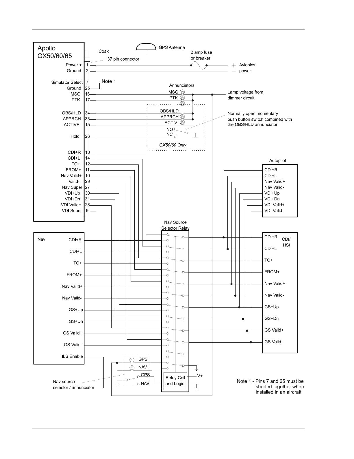
IGURE 11 APOLLO 50/60 CONNECTIONS WITH MD41 ANNUNCIATOR / RELAY............................ 21
F
F
IGURE 12 RS-232 SERIAL CONNECTIONS .................................................................................... 22
FIGURE 13 GX60/65 COMM WIRING DIAGRAM............................................................................. 23
FIGURE 14 GX60/65 TYPICAL AUDIO PANEL CONNECTIONS......................................................... 24
FIGURE 15 UNIT DIMENSIONS........................................................................................................ 34
FIGURE 16 - EXAMPLE ANNUNCIATORS.......................................................................................... 36
FIGURE 17 MOVING MAP DATA OUTPUT (EXTENDED DATA DISABLED)....................................... 61
FIGURE 18 MOVING MAP DATA OUTPUT (EXTENDED DATA ENABLED)........................................ 62
FIGURE 19 ALTITUDE DATA INPUT ................................................................................................ 68
FIGURE 20 FUEL / AIRDATA DATA INPUT (S FORMAT) .................................................................. 70
FIGURE 21 - FULL STACK INTERCONNECT DRAWING...................................................................... 75
Apollo GX50/60/65 Installation Manual
iii

Table of Contents
NOTES
iv Apollo GX50/60/65 Installation Manual

Introduction
SECTION 1 - INTRODUCTION
ABOUT THIS MANUAL
This manual describes the installation of the Apollo GX50 GPS and GX60/65 GPS/Comm
units. It is intended for use by persons certified by the Federal Aviation Administration (FAA)
to install aircraft navigation devices. It includes installation and checkout procedures for the
GX50, GX60, GX65 and units to standards described in FAA advisory circulars AC 20-138
(for GPS) and AC 20-67B (for comm).
The GX50 and GX60/65 units are equivalent except that the GX50 does not include the VHF
Comm. Throughout this manual, references to the GX50/60/65 are for the GX50, GX60, and
GX65. The GX65 differs from the GX60 in that it is not certified for IFR approaches.
Section 1
Section 2
Section 3
Section 4
Appendix A
Appendix B
Appendix C
Appendix D
Appendix E
Provides an introduction to the Apollo GX50/60/65 units. TSO certification
information is also included in this section.
Includes installation and checkout procedures.
Includes complete specifications.
Includes limitations for the equipment and installation.
Includes troubleshooting information.
Includes periodic maintenance requirements.
Includes the environmental qualification form.
Includes information on accessories.
Includes serial data specifications.
APOLLO GX50/60/65 DESCRIPTION
The Apollo GX50 GPS is a TSO-C129a/JTSO-C129a Class A1 GPS supplemental navigation
receiver for IFR en route, terminal, and non-precision approach operation. The unit features a
moving map display and a database provided by means of a plug-in data card for convenience
in changing and updating the database.
The Apollo GX60 GPS/Comm includes the same GPS capabilities as the GX50 and includes
a 760 channel VHF Comm transceiver. The Apollo GX65 includes the same GPS and Comm
capabilities as the GX60, except that it is not certified for non-precision approach. The GX65
has TSO-C129a/JTSO-C129a Class A2 authorization.
Apollo GX50/60/65 Installation Manual
1
Introduction
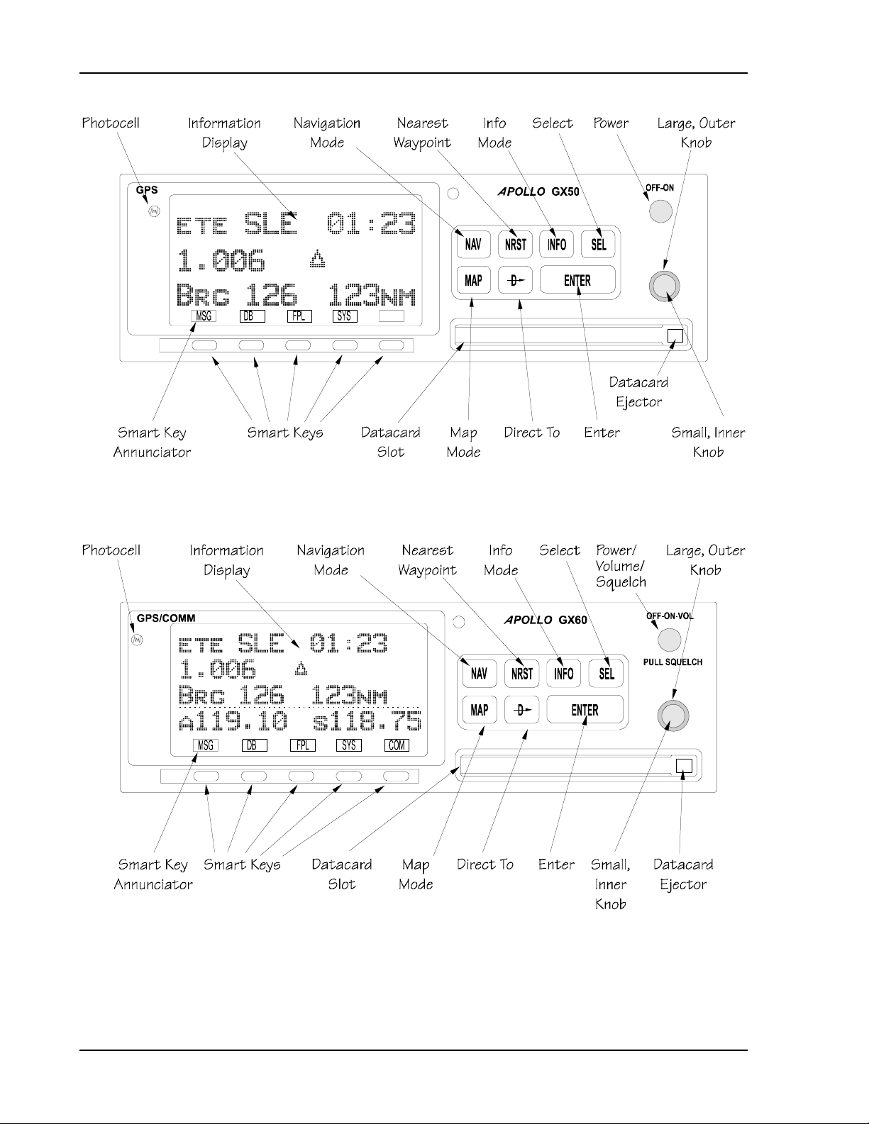
Figure 1 GX50 Front Panel
Figure 2 GX60/65 Front Panel
2 Apollo GX50/60/65 Installation Manual

Introduction
FEATURES
The GPS navigation features for the GX50 GPS and GX60/65 GPS/Comm include:
• High resolution, daylight readable graphics display
• Automatic display intensity
• Back-lit buttons
• Simple “Direct-To” navigation
• Datacard database for easy user update and replacement
• Nearest waypoint and airspace search (includes airports, VORs, LocDMEs, NDBs,
intersections, and user waypoints)
• Remote waypoint search
• Navigation displays -
− Lat/Lon to 0.01 minute
− Bearing and distance to waypoint
− Ground speed and track angle
− Track angle error
− Desired track and distance between waypoints
− Cross track error with numeric and graphic CDI
− Display of the “TO” waypoint ident
− ETE and ETA to the “TO” and destination waypoints
− Altitude (from altitude encoder/converter input)
− Minimum safe altitude and en route safe altitude information
• Map Displays -
− Full screen map with bearing, distance to waypoint, and zoom level
− Split screen map with distance, speed, bearing, track, crosstrack error, To
waypoint, and zoom level
− Split screen with nav data and comm frequency display (GX60/65 only)
− Smart key, 1 button map declutter, Tri-state
− On map waypoint selection for information, direct-to nomination
− Track up, desired track up, and magnetic north up options
− Runway diagrams and runway names displayed
− 5nm ATC rings around airports with control towers
− Airspaces displayed by sector or outer boundary
− Airspace display controllable by type
− Approach preview page (GX50/60 only)
− Route line displayed
• Automatic waypoint sequencing
• Vectors to final input (GX50/60 only)
• DME arc assist
• Built-in simulator for trip planning and training
• User definable navigation pages with auto sequencing
• 30 flight plans of 20 legs each
• 500 user waypoints created by lat/lon or by radial/distance from a reference waypoint
• Real time clock (time and date) in UTC
• Countdown timer
Apollo GX50/60/65 Installation Manual
3

Introduction
• Flight timer
• Automatic or manual magnetic variation
• Parallel track offset
• Alerts for -
− Loss of navigation data
− Arrival at waypoint
− Special use airspace
• Full range (10VDC to 40VDC) input supply voltage
The VHF Comm features of the GX60/65 GPS/Comm include:
• 760 channels
• Frequency range of 118.000 to 136.975 MHz
• Active and standby frequency display
• Transmit status indicator
• Stuck mic time-out
• Frequency monitor function - listen to Standby frequency while monitoring Active
frequency for any activity
• Weather channels - tune in to National Weather Service channels
• Built-in intercom function
• Frequency memory and recall functions
− from navigation data base
− 10 last used
− 10 user stored
• Two microphone inputs
• 12 watt audio amplifier
• Remote flip/flop input
SYSTEM CONFIGURATIONS
The GX50/60/65 can be installed in several configurations based upon individual
requirements. This includes VFR or IFR GPS navigation. This section defines the minimum
requirements.
VFR GPS NAVIGATION INSTALLATION
When installed for VFR operation, the GX50/60/65 requires only the following minimal
connections.
• an A-33 or A-34 GPS antenna
4 Apollo GX50/60/65 Installation Manual
• power input
The GX50/60/65 can also be connected to other external devices such as:
• an external non-numeric indicator, such as a CDI or HSI
• external lamp annunciators including “MSG” and “PTK”
• an “OBS/HLD” external annunciator (with switch)
• an autopilot
• a moving map display connected to an RS-232 serial output

Introduction
• an altitude encoder/converter
• Fuel/Airdata Computer (e.g. Shadin Model ADC-200)
When the GX50/60/65 is installed for VFR, a placard stating “GPS Limited to VFR Use
Only” or an FAA approved equivalent statement must be placed next to the primary indicator.
IFR GPS NAVIGATION INSTALLATION
When installed for IFR operation, the GX50/60/65 requires connections to several external
indicators. The minimum connections for IFR operation are as follows.
• an A-33 or A-34 GPS antenna
• power input
• an external non-numeric indicator, such as a CDI or HSI
• external lamp annunciators including “MSG” and “PTK”
For TSO-C129a A1 (non-precision approach) operation the following connections are also
required (GX65 not included):
• external lamp annunciators including “APPRCH” and “ACTIVE”
• an “OBS/HLD” external annunciator (with switch)
• altitude input from an altitude encoder/converter or air data computer
The GX50/60/65 can also be connected to other external devices such as:
• an autopilot
• a moving map display connected to an RS-232 serial output
• an SL40 VHF Comm radio connected to an RS-232 serial output (For GX50 units)
• Fuel/Airdata Computer (e.g. Shadin Model ADC-200)
COMM TRANSCEIVER - GX60/65
For standalone installations, the comm requires connections to:
• a standard comm antenna
• a microphone (or microphones)
• a speaker or headphone
• power input
The microphone and speaker or headphones may be installed dedicated to the GX60/65
comm, or by connection to an audio panel.
The comm installation can also include optional connections:
• external remote flip-flop button
DATABASE UPDATES
The GX50/60/65 utilizes a Flybrary database stored on a standard plug-in memory card for
easy updating and replacement. Simply plug in the new datacard to update your existing
database or change to a new database.
Contact the Garmin AT factory for information on databases available for the GX50/60/65.
Apollo GX50/60/65 Installation Manual
5

Introduction
REGULATORY COMPLIANCE
The Apollo GX60/65 is designed and tested to meet the following TSO/JTSOs:
FAA TSO-C37d/JTSO-2C37e Class 4 for transmit
FAA TSO-C38d/JTSO-C38e Class D for receive
FAA TSO-C128/JTSO-2C128 for unintentional transmission (stuck mic)
FAA TSO-C129a /JTSO C129a (GX60 – Class A1, GX65 – Class A2) for GPS
navigation
The Apollo GX50 is designed and tested to meet the following TSO/JTSOs:
FAA TSO-C129a/JTSO-C129a Class A1 for GPS navigation
The Apollo GX60/65 comm complies with the FCC requirements specified in:
CFR 47, Part 87, Aviation Services, Subpart D, Technical Requirements
The Apollo GX50 and GX60/65 comply with the FCC requirements specified in:
CFR 47, Part 15, Radio Frequency Devices, Subpart B, Unintentional Radiators
The Apollo GX50/60/65 software is designed and tested to RTCA/DO-178B, level C and ED12B Level C.
Note: Unauthorized changes or modifications to the GX50/60/65 may void the
compliance to regulatory agency requirements and authorization for continued
equipment usage.
UNPACKING THE EQUIPMENT
Carefully unpack the equipment. Visually inspect the package contents for any evidence of
shipping damage. Retain all shipping containers and packaging material in case reshipment is
necessary.
PACKAGE CONTENTS
As shipped from the Garmin AT factory, the Apollo GX50/60/65 package includes most items
necessary for installation other than supplies normally available at the installation shop, such as
wire and cable ties, and required input and output equipment. The standard items included in the
package are listed in Table 1.
6 Apollo GX50/60/65 Installation Manual

Introduction
Table 1 Package Contents
Part # Description Qty
GX50 GX60 GX65
Units
430-6050-4xx GX50 GPS 1
430-6050-6xx GX60 GPS / Comm 1
430-6050-8xx GX65 GPS / Comm 1
Install kits Part number: 424-2007- -4xx -6xx -8xx
162-0100 15-pin dsub connector shell 1 1
162-0103 37-pin dsub connector shell 1 1 1
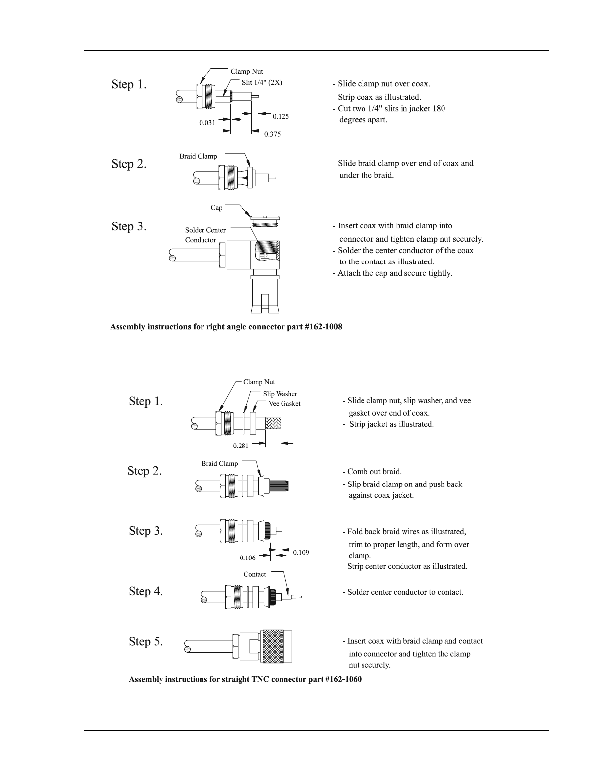
162-1008 Right angle coax plug 1 2 2
162-1060 TNC coax connector 1 1 1
202-0001 Cable tie 2 4 4
204-0037 Edge grommet 6” 6” 6”
204-2100 Shoulder bushing 2 4 4
221-0400 4-40 x 1/4 SS pan head Phillips machine screw
4 4 4
with lock washer
224-0404 4-40 x 1/4 SS flat head Phillips machine screw 6 8 8
245-0022 Crimp contact for dsub, 20 to 24 awg wire 37 52 52
310-5184-xx Mounting frame 1 1 1
310-5188-xx Connector mounting plate 1 1 1
998-0048 3/32 hex driver 1 1 1
Manual kits Part number: 564-0064- -4xx -6xx -8xx
560-0961-xx GX GPS User’s Manual 1 1 1
560-0959-xx GX50 / GX60 Installation Manual 1 1 1
560-0928-xx GX GPS Approach User’s Manual Insert 1 1
560-0963-xx GX60 Comm User’s Manual Insert 1 1
560-9000 Binder, 5½ x 8½ x 1” 3 ring 1 1 1
561-0236-xx GX60/65 Quick Reference Guide 1 1
561-0238-xx GX50 Quick Reference Guide 1
Accessories
560-0949-xx A-33 Installation Guide 1 1 1
590-1104 A-33 GPS Antenna 1 1 1
Note: Package contents may vary depending on how the unit is ordered.
Apollo GX50/60/65 Installation Manual
7

Introduction
OTHER REQUIRED MATERIALS
The GX50/60/65 is intended for use with standard aviation accessories. External devices
required for various installations are listed in the System Configurations section on page 4.
Depending upon the installation, this will include items such as:
• annunciators
• a CDI or HSI
• a comm antenna
• a microphone(s)
• a speaker or headphones
SPECIAL TOOLS REQUIRED
Crimp Tool
A crimp tool meeting MIL specification M22520/1-01 and a positioner/locater are required to
ensure consistent, reliable crimp contact connections for the rear d-sub connectors. These tools
are available from:
For pin p/n 245-0022
Astro Tool Corp. Phone (503) 642-9853
21615 SW TV Highway Fax (503) 591-7766
Beaverton, OR 97006
Crimp tool: Astro Tool part #615708
Positioner: Astro Tool part #616356
For pin p/n 245-0027
ITT Cannon Phone (714) 261-5300
1851 E. Deere Ave. Fax (714) 575-8324
Santa Ana, CA 92705-6500
Insertion tool: ITT part # 274-7006-000 (Desc. CIET-20HD)
Regular duty Crimp tool: ITT part #995-0001-585 (Desc. M22520/1-01)
Regular duty Locator tool: ITT part #995-0001-244 (Desc. TH25)
Heavy duty Crimp tool: ITT part #995-0001-584 (Desc. M22520/2-01)
Heavy duty Locator tool: ITT part #995-0001-604 (Desc. M22520/2-08)
LICENSE REQUIREMENTS
An aircraft radio station license is required for operation of the GX60/65 comm transmitter
once installed in the aircraft. An application must be submitted on FCC Form 404, which may
be obtained from the FCC in Washington, DC, or any of its field offices. Procedures for
applications are in CFR 47, Part 87, Aviation Services, Subpart B, Applications and Licenses.
8 Apollo GX50/60/65 Installation Manual

Installation
SECTION 2 - INSTALLATION
This section describes the installation of the GX50 and GX60/65 including mounting, wiring,
and connections. A post installation check-out procedure is included at the end of this section.
PRE-INSTALLATION INFORMATION
Always follow good avionics installation practices per FAA Advisory Circulars (AC) 43.13-1A,
43.13-2A, AC 20-138, and AC 20-67B, or later FAA approved revisions of these documents.
Follow the installation procedure in this section as it is presented for a successful installation.
Read the entire section before beginning the procedure. Perform the post installation checkout before closing the work area in case problems occur.
INSTALLATION OVERVIEW
A successful installation should start with careful planning including determination of
mounting location for the GX50/60/65, antenna mounting, cable routing, and other required
modifications. Once the mounting location has been determined, prepare the mounting frame
for installation. It may be easier to complete the wiring harness and attach the connectors to
the mounting frame before installing the mounting frame.
INSTALLATION CONSIDERATIONS
MOUNTING CONSIDERATIONS
The GX50/60/65 is designed to mount in the avionics stack in the aircraft instrument panel
within easy view and reach of the pilot. The standard package includes a mounting frame for
ease of mounting, connections, and service of the unit. Allow an additional one inch clearance
to the rear of the mounting frame for connectors and cables.
For typical installations, the GX50/60/65 does not require external cooling. When mounting the
unit, ensure that a clearance of 1/8 to 1/4 inch exists between avionics units to allow for air
circulation.
MINIMUM SYSTEM CONFIGURATION
The minimum system configuration and external connection requirements are described in the
System Configurations section on page 4.
ALTITUDE INPUT
The GX50/60/65 includes an altitude input, which is used by the GPS RAIM calculations as
well as providing for altitude assist functions such as altitude preset and hold and 3D airspace
alerts. The altitude input is required for installations approved for non-precision approach
operation, optional for other installations.
The GX50/60/65 altitude input can be connected from either an altitude encoder/converter or
an air data converter. The minimum requirements for the altitude input are listed in the
specifications on page 36.
Apollo GX50/60/65 Installation Manual
9

Installation
HELICOPTER REQUIREMENTS
The GX60 and GX65 is qualified for helicopter installation with certain mount tube and
GX60/65 configurations (see Section 4 - Limitations).
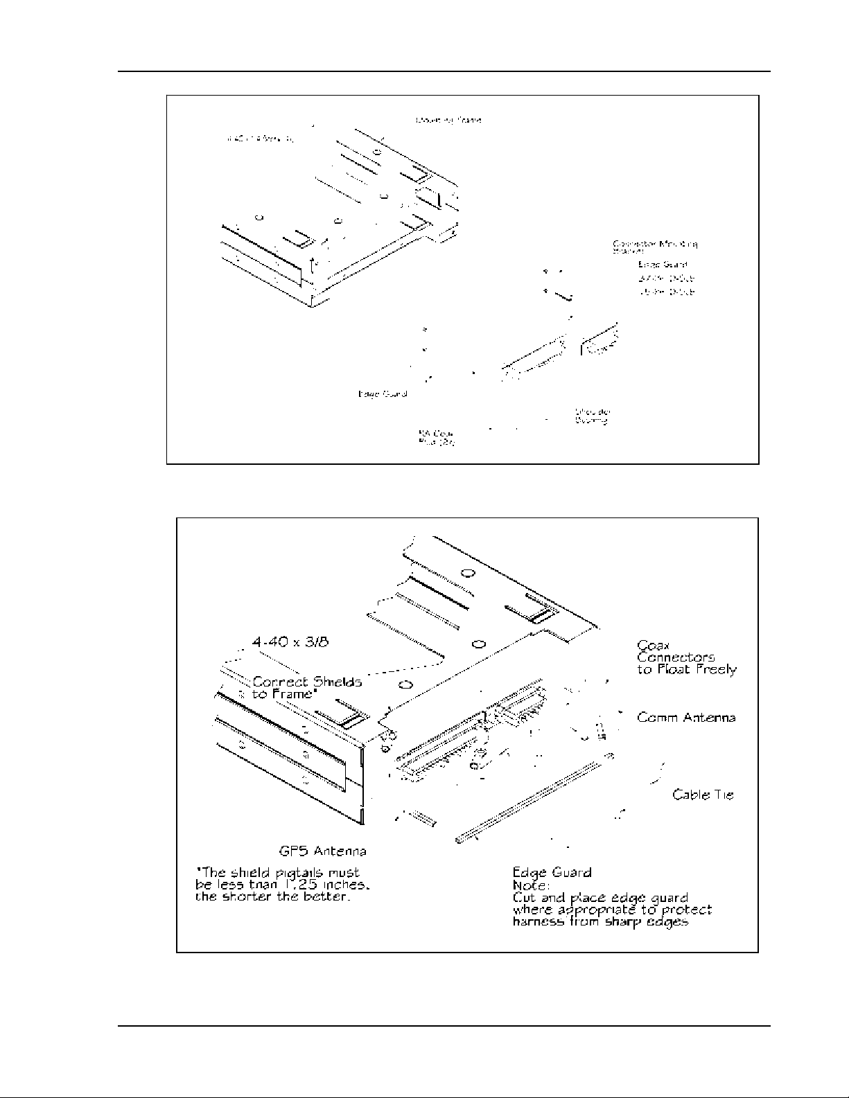
EQUIPMENT MOUNTING
Once the cable assemblies have been made, attach the 15 and 37 pin d-sub and coaxial cable
connectors to the rear connector mounting plate and the mounting frame as illustrated in Figure 4
and Figure 5. Route the wiring bundle as appropriate. The rear connector plate should be attached
to the mounting frame before installing the frame in the instrument panel. The rear connector
plate can be used to tie down the cable assemblies. Use the supplied edge guard to protect the
cable from sharp edges. Connect the shield grounds directly to the connector mounting plate.
Once the cable assemblies, the connector mounting plate, and the mounting frame are
assembled, install the mounting frame assembly in the instrument panel as illustrated in
Figure 3. Be sure to use low profile head screws so the unit will slide in and out freely. Attach
the front of the mounting frame to the instrument panel. Use support brackets to attach the
rear of the frame to the aircraft.
10 Apollo GX50/60/65 Installation Manual
Installation
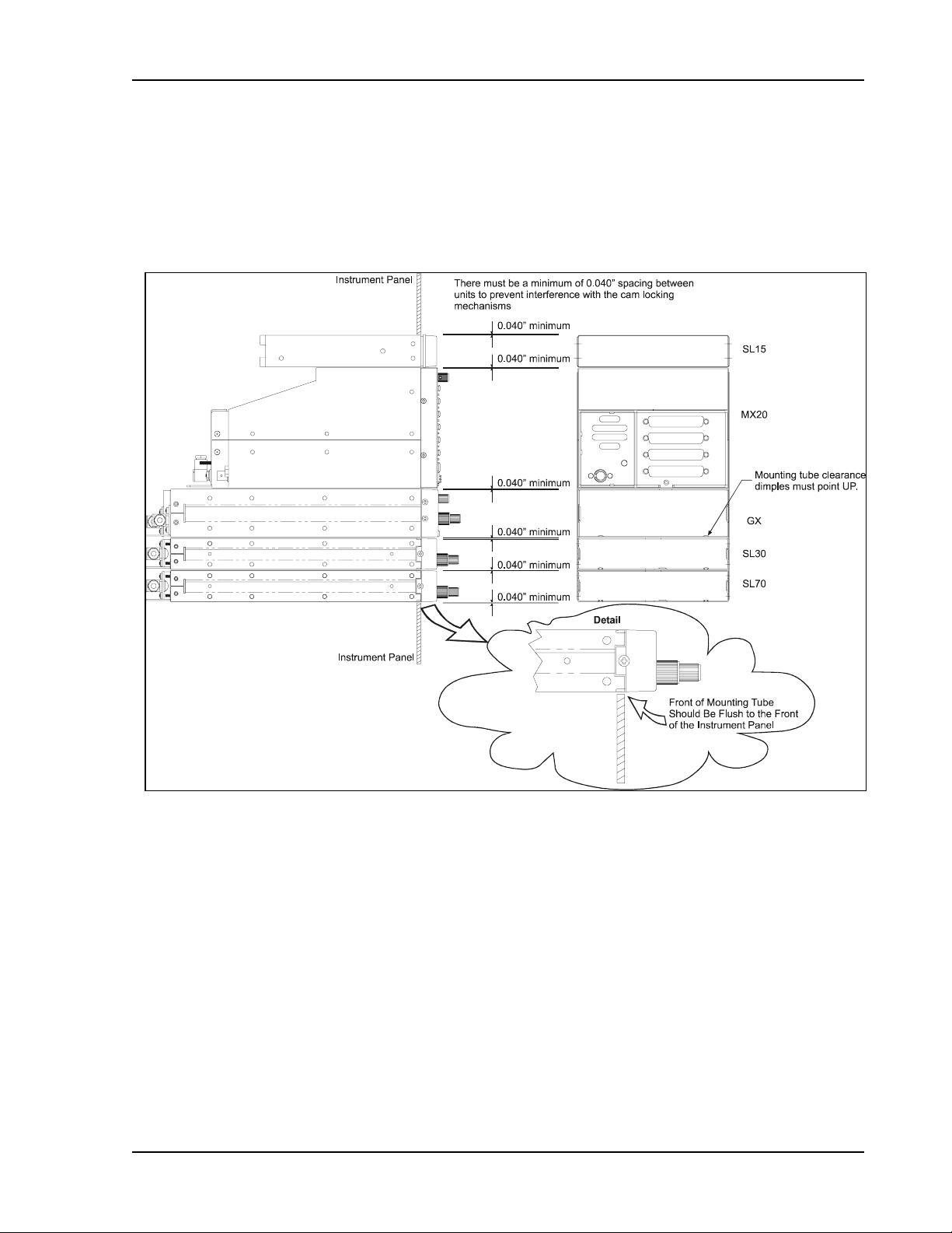
MOUNTING TUBE INSTALLATION
Care must be taken when installing the mounting tube to ensure you can properly insert and
secure the unit. There must be a minimum vertical spacing of 0.040 inches between units to
prevent interference with the cam locking mechanisms. Mounting tubes with clearance
dimples help maintain the proper clearance. The mounting tube must be installed with the
clearance dimples pointing up.
Figure 3 - Full Stack Mounting Tube Spacing
The mounting tube should be flush to the instrument panel and allow sufficient clearance for the
back of the bezel of the unit to mount flush to the mounting tube. Sufficient clearance must exist
in the instrument panel opening to allow ease of insertion and removal of the unit. If the back
of the unit bezel does not mount flush to the mounting tube, the connector may not
engage fully.
Secure the mounting tube to the instrument panel structure. Mounting screw heads must not
protrude into the mounting tube. Be sure to use the appropriate screws so the unit will slide in
and out freely. The screws attaching the mounting tube to the instrument panel structure must
not interfere with the insertion of the unit. Failure to prevent interference will result in damage
to the unit or prevent its insertion. Take care that the mounting tube is not distorted when it is
attached to the instrument panel and structural supports. Shims may be necessary to properly
install the mounting tube. If the mounting tube is distorted out of square, the unit may either bind
when being inserted or the cam lock may not engage.
Apollo GX50/60/65 Installation Manual
11
Installation
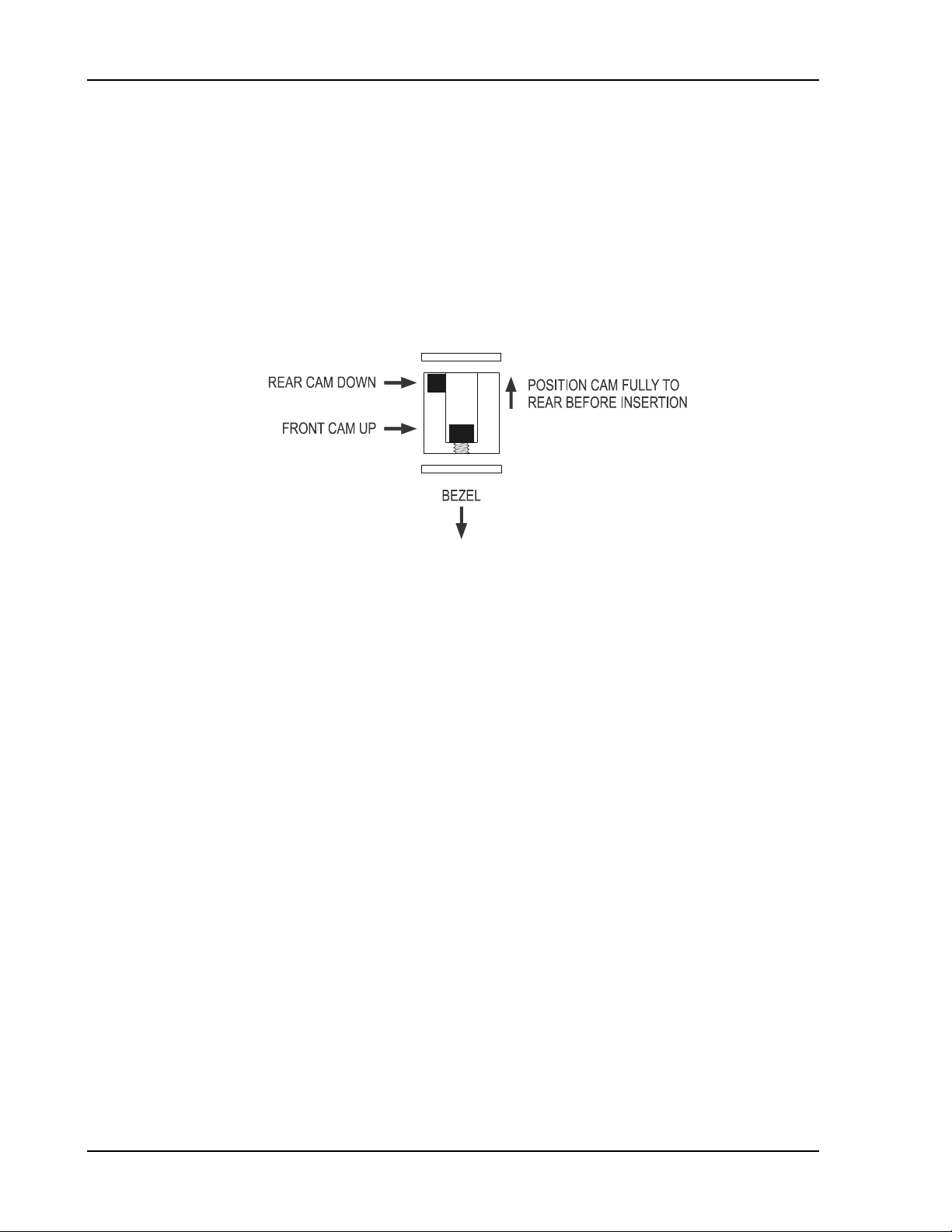
UNIT INSERTION
Position the cam lock as shown below. The front lobe of the cam should be vertical. The cam
lock mechanism should be fully unscrewed (turned counter-clockwise). Slide the unit into the
frame. Turn (clockwise) and carefully hand-tighten (4 in-lb max.) the cam lock mechanism
using only the 3/32" hex driver provided in the installation package. Using a larger tool than
the one provided makes it easy to exceed the allowable torque on the cam lock resulting in
damage to the unit. The unit will be pulled into the frame securing the unit and the connectors
will fully engage. Do NOT overtighten. The back of the bezel must only be flush to the
mounting tube. If the cam lock is hard to turn or the unit does not seat fully, the unit is
probably binding and the mounting tube should be checked.
UNIT REMOVAL
To remove the unit from the mounting frame, turn the screw counter-clockwise with the hex
driver to unscrew the cam lock mechanism. The unit will begin to pull away from the
mounting tube. Turn the screw until slight resistance is felt and then pull the unit from the
frame. Do not exert excessive turning force at the end of the cam lock travel or the unit
may be damaged. With the cam lock fully disengaged, pull the unit straight out holding onto
the sides of the bezel. It is not recommended that you pull the unit out by the rotary knobs. No
special extraction tools are required, if the mounting tube is properly installed.
12 Apollo GX50/60/65 Installation Manual
Installation
Figure 4 Mounting Frame Assembly
Figure 5 Cable Routing
Apollo GX50/60/65 Installation Manual
13

Installation
ELECTRICAL CONNECTIONS
Wiring necessary for installation of the GX50/60/65 includes the rear panel electrical
connections and the antenna cable placement. The 15 and 37 pin d-sub connectors and coax
connector(s) may be wired before or after being installed in the mounting frame. The
recommended connecting wire size for the connectors is 20 to 24 AWG. Wiring diagrams are
included on pages 18 through 24.
POWER
The GX60/65 requires two power connections, one for the GPS navigation side of the unit, the
other for the comm. Make the power connections to the unit using 20 AWG wire.
The GPS navigation power input is internally fused at 3 amps. A separate 2 amp (maximum)
circuit breaker or fuse should be installed for downline overload or short circuit protection.
The comm power input (GX60/65 only) is internally fused at 7 amps. A separate 5 amp (maximum)
circuit breaker or fuse should be installed for downline overload or short circuit protection.
Note: Circuits should be protected in accordance with guidelines in AC 43.13-1A,
chapter 11, section 2, paragraph 429.
Warning
When connecting power to the GX unit, reversing the polarity of the connection
will blow the internal fuse. The internal fuse is soldered onto the circuit board
and requires repair at the factory.
AVIONICS OUTPUTS
The GX50/60/65 includes avionics outputs for CDI/HSI indicators, autopilot, and
annunciators. These outputs are to be connected as appropriate for the particular installation.
The CDI/HSI outputs may be connected to a dedicated CDI or HSI or to a shared indicator
using an appropriate switching relay. The avionics outputs available are listed in the Avionics
Outputs specification on page 35. Connect the annunciator outputs to lamp indicators as
described in the specifications. The minimum connections required for different installations
are listed in the System Configurations on page 4.
If a switching relay is used to make connections to a shared CDI/HSI, it should be a minimum
of an eight pole relay box with an appropriate selector switch with annunciation. The ILS
enable signal (see Figure 8 and Figure 11) from a connected ILS receiver can be connected to
automatically switch the indicators back to the nav receiver when an ILS frequency is
selected.
SERIAL INTERFACE
The GX50/60/65 includes two RS-232 serial ports for making optional connections. The serial
ports can be used for connecting to such devices as the Apollo SL40 comm, a moving map
display, multi-function display, autopilot, VHF Nav/Com, Fuel Air/Data computer, or an
altitude encoder/converter. Serial output connections should be limited to no more than three
external units.
When making connections to the GX50/60, use a three-conductor shielded cable (for two-way
serial communication) or a two-conductor shielded cable (for one-way serial communication).
Make RxD, TxD, and signal ground connections to the 37-pin connector. Connect the shield(s)
to the rear of the mounting frame. The shield leads must be <1.25 inches. See Figure 5.
Complete serial interface specifications are included in Appendix E.
14 Apollo GX50/60/65 Installation Manual

Installation
SPEAKER AND HEADPHONE OUTPUTS (GX60/65 ONLY)
Connect the speaker and headphones to the output pins on the rear connector.
MICROPHONE INPUTS (GX60/65 ONLY)
Microphone input connections should be made using a twisted pair shielded cable. Attach the
signal ground to the mic ground pin on the rear connector and connect the shield to the rear
connector plate.
TRANSMIT KEY INPUT (GX60/65 ONLY)
The TxKey input on the rear connector must be pulled low to ground to enable the transmitter. This
input should be connected to a microphone or yoke mounted momentary push button switch.
INTERCOM SELECTOR SWITCH (GX60/65 ONLY)
The GX60/65 includes a voice activated intercom function that can be enabled by an external
control switch. This is an optional connection.
When making connection for the intercom selection, connect the intercom selection input to a
remote mounted normally open switch. A momentary toggle or alternate action switch can be
used. Connect the other terminal of the switch to ground. The intercom function is enabled
when the input is pulled low to ground. The monitor function is inhibited when the intercom
function is selected.
REMOTE FLIP/FLOP INPUT (GX60/65 ONLY)
The GX60/65 includes a remote flip/flop input. This is an optional input that can be connected
to a remote mounted (such as on the yoke) momentary push button switch which pulls the
input low to ground.
ANTENNA INSTALLATION AND CONNECTIONS
COMM ANTENNA (GX60/65 ONLY)
The GX60/65 requires a standard 50Ω vertically polarized antenna. Follow the antenna
manufacturer’s installation instructions for mounting the antenna.
The antenna should be mounted on a metal surface or a ground plane with a minimum area of
18 x 18 inches. The antenna should be mounted a minimum of two feet away from GPS
antennas.
The comm antenna should also be mounted as far apart as practical from the ELT antenna,
preferably one on top and the other on the bottom of the aircraft fuselage. Some ELTs have
exhibited re-radiation problems generating harmonics that may interfere with GPS signals.
This can happen when the comm (GX60/65 or any other comm) is transmitting on certain
frequencies such as 121.15 or 121.175 MHz, which may cause the ELT output circuit to
oscillate from the signal coming in on the ELT antenna coax.
The antenna coax cable should be made of RG-142B or a comparable quality 50Ω coax.
Assembly instructions for the rear coax connector are included in Figure 6.
Apollo GX50/60/65 Installation Manual
15

Installation
GPS ANTENNA
The mounting location and cable connections for the GPS antenna are very important. The
antenna should be mounted no closer than two feet from VHF comm transmitter antennas, six
inches from other antennas emitting less than 25 watts, and two feet from higher power
antennas. Special care should be taken to ensure that the GPS antenna is not mounted in close
proximity to antennas that may emit harmonic interference at the L1 frequency of
1575.42 MHz. Refer to the antenna installation manual for installation instructions.
The connectors are included in the installation kit, and are intended for use with RG-142B size
coax cable. If using a different diameter coax, alternative connectors may be required. Assembly
instructions for the connectors are included in Figure 6 and Figure 7. RG-142B cable can be used
as long as the length is less than 20 feet. For longer lengths, use a low loss 50Ω coax.
Suggestion: Temporarily locate the GPS antenna with coax connected to the GX50/60/65 and
check the GPS performance as described in the GPS Operation and Position test in the Post
Installation Checkout on page 27. Once a suitable location has been verified, then
permanently mount the antenna.
Note: If using a GPS antenna that was already on the aircraft, or if mounting the antenna
closer than two feet from a comm antenna, conduct the GPS Operation and Position test in
the Post Installation Checkout on page 27. If the GX50/60/65 passes the test, then moving the
antenna is not necessary.
Once the antenna mounting position has been prepared, route the coax cable from the antenna
to the GX50/60/65. Proper selection of coax cable and assembly of connectors is critical to
GPS signal performance. The cable loss from the antenna to the GX50/60/65 should be
limited to a maximum of 4 dB. Minimize the coax length for optimum performance and DO
NOT coil excess cable. Leave only enough for service loops. The coaxial connectors and
adapters, such as TNC to BNC, add additional loss to the cable and should be considered
when computing the maximum 4 dB loss. A typical loss of 0.2 dB can be used for each
connection. The typical cable loss for 20 feet of RG-142B coax with a connector on each end
is 4 dB.
During the post-installation checkout, susceptibility to harmonics of VHF comm transmitters
will be evaluated. If problems arise, then better isolation, or distance, may be required
between the GPS and comm antennas, or a notch filter may be installed in series with the
antenna coax of the VHF comm transceiver to reduce or eliminate the harmonic interference.
A notch filter for this use (part #162-1059) is available from Garmin AT.
Note: GX60/65 performance has been verified in typical installations and has not shown
problems with the built-in comm interfering with the GPS when installed according to
If a VHF comm transmitter causes problems with the GPS on the selected frequencies as
listed in the post-installation checkout, the problem may be due to the ELT. This can be
verified by disconnecting the ELT antenna coax at the ELT unit. If the ELT is found to cause
the problem, then contact the ELT manufacturer or replace the ELT.
the recommended installation guidelines.
16 Apollo GX50/60/65 Installation Manual
Installation
Figure 6 Rear Coax Connector Assembly
Figure 7 TNC Coax Connector Assembly
Apollo GX50/60/65 Installation Manual
17
Installation
Figure 8 GX50/60/65 Power and Avionics Connections
18 Apollo GX50/60/65 Installation Manual
 Loading...