

Garmin Apollo GX 50 Training Package
Apollo GX50
Dealer/Customer
Training Package
II MORROW
VISIONARY THINKING TODAY

II Morrow and Apollo are trademarks of II Morrow Inc.
© 1998 by II Morrow Inc. All rights reserved.
Printed in the U.S.A.
II Morrow Inc.
II MORROW
VISIONARY THINKING TODAY
Consumer Products Division
2345 Turner Road, S.E.
Salem, OR 97302
U.S.A. Toll Free 800.525.6726
Canada Toll Free 800.654.3415
International 503.391.3411
FAX 503.364.2138
Visit our web page at http://www.iimorrow.com
Send comments about this manual by email to: techpubs@iim.ups.com

Table Of Contents
Getting Started the First Time......................1
Power On ........................1
Seed Position ......................1
Entering a Seed Position ................2
Change Reference Waypoint ..............2
Using the Direct-To Function..............3
Waypoint Information .................4
Navigation Basics ................................5
Estimated Time En Route (Ete).............5
Bearing (Brg) ......................5
Range (Rge).......................5
Course Deviation Indicator (CDI) and
Distance Off Track ...................6
Desired Track (Dtk)...................7
Leg (FROM-TO) Distance ...............7
Track (Trk) Angle....................7
Track Angle Error (Tae) ................7
Ground Speed (GS) ...................7
Minimum Safe Altitude (MSA).............8
Minimum En Route Safe Altitude (MESA) ......8
Flight Time .......................8
Time UTC........................9
Estimated Time of Arrival (ETA) ...........9
Nearest Waypoint Search ................9
Starting Nearest Waypoint Search ...........9
Searching Around a Reference Waypoint .......10
From/To/Next Waypoint ...............11
Creating FROM/TO/NEXT Waypoints (ABCD) ...11
Placing the TO Waypoint on Hold ..........14
Using Direct-To ....................14
Direct-To Defaults...................15
Direct-To Operation ..................15
Direct-To Examples ..................16
Center the CDI.....................16
Enter a New Waypoint into a Flight Plan .......17

Waypoint Database ..............................19
Create User Waypoint by Lat/Lon ..........19
Create User Waypoint by Radial/Distance ......19
Flight Plan Functions ............................21
Flight Plan Pages ...................21
Reaching the Flight Plan Function ..........21
Active Flight Plan ...................21
Creating a Flight Plan .................22
Flight Plan Sequencing ................24
Flight Plan Leg Information ..............24
Moving Map Functions...........................25
Full Screen Map ....................25
Controls ........................25
Map Scale .......................25
Map and Nav Info ...................26
Map Setup .......................26
Route Line .......................26
Map Orient.......................26
Identifier and Waypoint Type Selection........27
Airspace Setup.....................28
Airspace Buffers....................28
ATC Ring Selection ..................29
Airspace Selections ..................30

Dealer/Customer Check Off Sheet
Getting Started the First Time......................1
Power On ........................1
Seed Position ......................1
Entering a Seed Position ................2
Change Reference Waypoint ..............2
Using the Direct-To Function..............3
Waypoint Information .................4
Navigation Basics ................................5
Estimated Time En Route (Ete).............5
Bearing (Brg) ......................5
Range (Rge).......................5
Course Deviation Indicator (CDI) and
Distance Off Track ...................6
Desired Track (Dtk)...................7
Leg (FROM-TO) Distance ...............7
Track (Trk) Angle....................7
Customer
Dealer
Track Angle Error (Tae) ................7
Ground Speed (GS) ...................7
Minimum Safe Altitude (MSA).............8
Minimum En Route Safe Altitude (MESA) ......8
Flight Time .......................8
Time UTC........................9
Estimated Time of Arrival (ETA) ...........9
Nearest Waypoint Search ................9
Starting Nearest Waypoint Search ...........9
Searching Around a Reference Waypoint .......10
From/To/Next Waypoint ...............11
Creating FROM/TO/NEXT Waypoints (ABCD) ...11
Placing the TO Waypoint on Hold ..........14
Using Direct-To ....................14
Direct-To Defaults...................15
Direct-To Operation ..................15
Direct-To Examples ..................16
Center the CDI.....................16
Enter a New Waypoint into a Flight Plan .......17
Please detach and return to II Morrow

Dealer/Customer Check Off Sheet
Waypoint Database ..............................19
Create User Waypoint by Lat/Lon ..........19
Create User Waypoint by Radial/Distance ......19
Flight Plan Functions ............................21
.................................................
Flight Plan Pages ...................21
Reaching the Flight Plan Function ..........21
Active Flight Plan ...................21
Creating a Flight Plan .................22
Flight Plan Sequencing ................24
Flight Plan Leg Information ..............24
Moving Map Functions...........................25
Full Screen Map ....................25
Controls ........................25
Map Scale .......................25
Customer Dealer
Map and Nav Info ...................26
Map Setup .......................26
Route Line .......................26
Map Orient.......................26
Identifier and Waypoint Type Selection........27
Airspace Setup.....................28
Airspace Buffers....................28
ATC Ring Selection ..................29
Airspace Selections ..................30
Dealer Name: _____________________________________
Dealer Address: ___________________________________
___________________________________
___________________________________
Dealer No.: _________________
Customer Name: __________________________________
Serial Number: ____________________________________
Please detach and return to II Morrow
Getting Started the First Time
This section explains how to get started using your Apollo GX50. Information in
this section explains how to startup the unit, check signals from the GPS satellites,
enter a seed position, and go Direct-To a destination waypoint.
It is necessary to enter a seed position and the current time the first time you
turn the unit on.
Getting Started the First Time
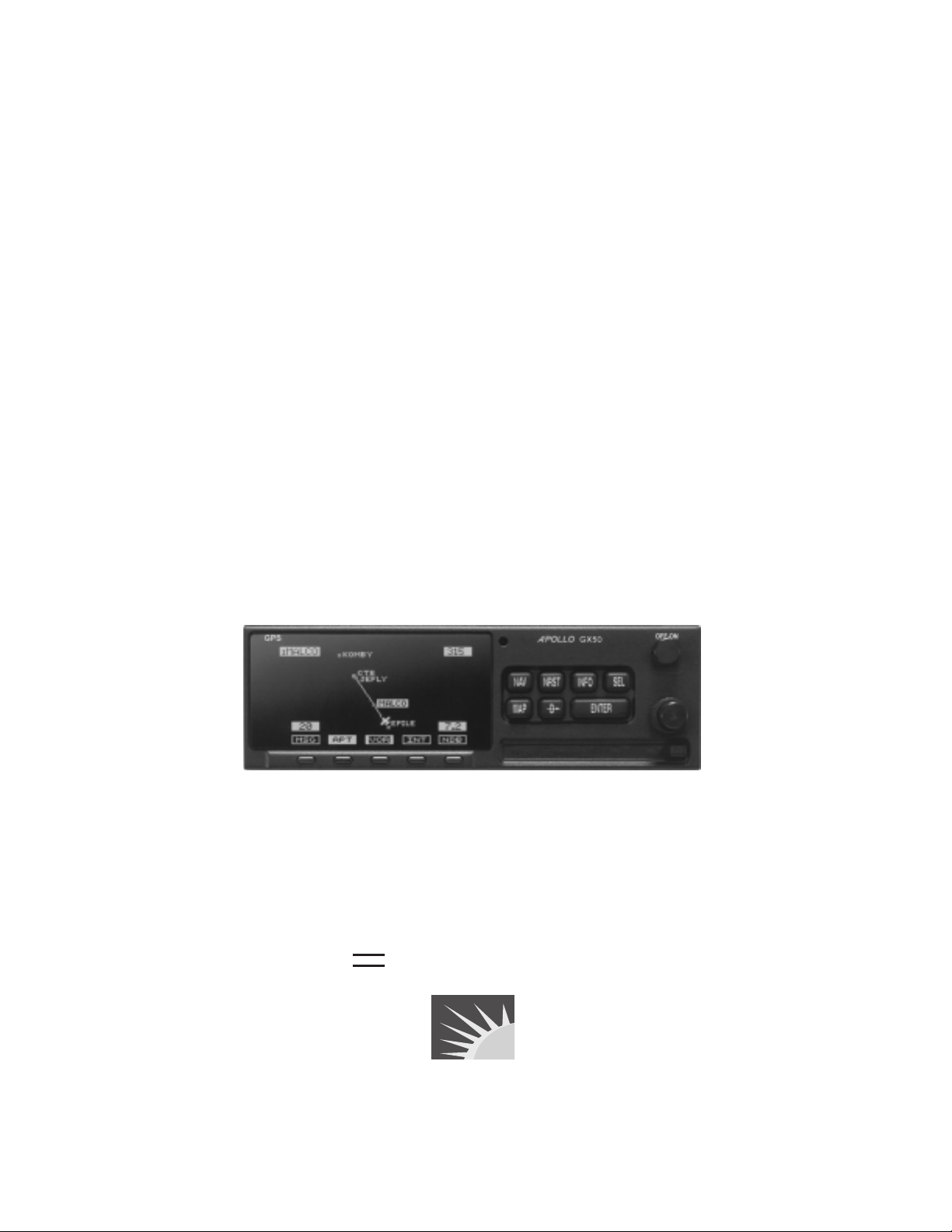
Information
Display
ete SLE 01:23
1.006
Brg 126 123nm
MSG
Smart Key
Annunciator
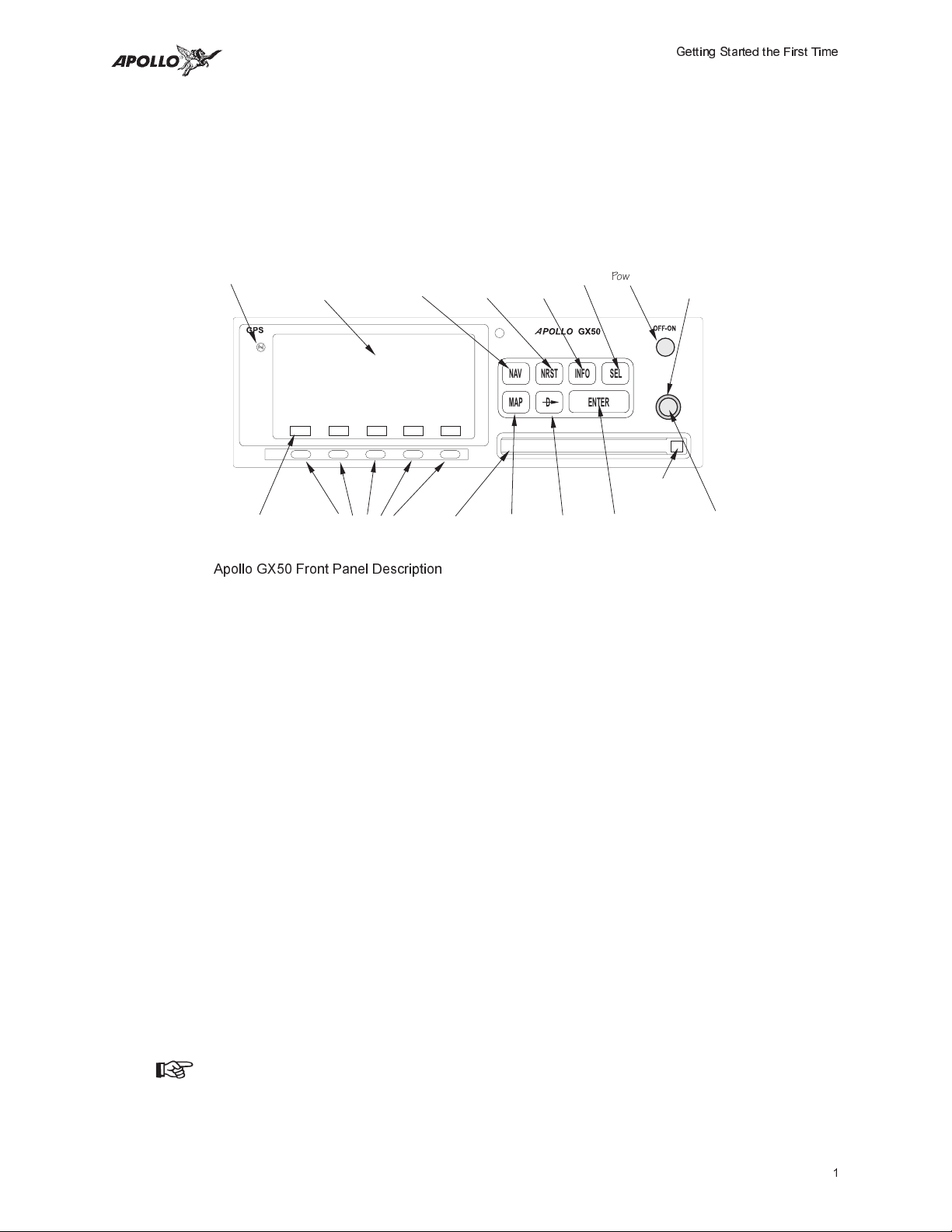
Apollo GX50 Front Panel Description
• Power on
•
Enter a seed position (your dealer may have already completed this step for you),
Navigation
Smart Keys
Mode
“
Info
Waypoint
NAV
SYSFPLDB
Slot
Mode
Select
Mode
A
NRST INFO SEL
D
Direct ToMap
PowerPhotocell Nearest
ENTERMAP
EnterDatacard
Large, Outer
Knob
Datacard
Ejector
Small, Inner
Knob
if necessary
•
Check satellite signal strength
•
Enter a “Direct-To,” or destination, waypoint
•
Begin navigating
Power On Turn the Power knob clockwise to switch the unit on. The startup screen, testing,
position, and database information shows on the display for several seconds and
then will go into the Navigation function.
Seed
Position
Each time the Apollo GX50 is switched on, it must locate satellites in the sky to
acquire signals before determining a position fix in a complex process involving
lengthy mathematical operations. Without a seed position and the current UTC time
and date, this process can take 10 minutes or more to complete. Enter a Seed Position
to allow the receiver to quickly locate and track available satellites.
Note
The seed position and current time only need to be entered the first
time the receiver is switched on. This information is stored in memory
and need not be entered again. If you move about three hundred miles
1
Getting Started the First Time
without the Apollo GX50 turned on and tracking its position, reenter
the seed position.
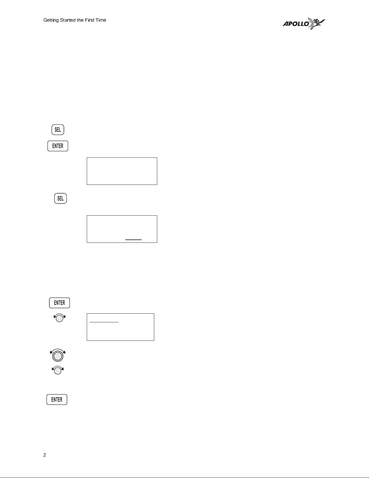
Entering a
Seed
Position
SEL
ENTER
1. The previous Seed Position will display with the choice of SEL to change the Seed
2. Press SEL to change the Seed Position.
SEL
3. The current Reference Position will be displayed and the Chg? prompt will flash.
After the start up tests, you will always have the choice of entering a Seed
Position. The Seed Position is a starting reference point so the GPS receiver
knows what satellites to look for. If a Seed Position has been previously entered,
you do not need to select a new Present Position or a Reference Waypoint. If you
do not make any selections, the Apollo GX50 will automatically progress into the
Navigation function.
Position or ENTER to accept the previous position. If you don’t do anything, the
Apollo GX50 will continue normally. You can also press ENTER to accept the current
position, though this is not required.
Ppos: 2.3nm 130°
To Nrst Wpt SLE
Ent-OK SEL-Chnge
Ppos: 44°54.46N
122°59.69W
Ref Wpt: Chg
?
ENTER
ENTER
Press ENTER to change the Reference Waypoint or turn the Large knob to
change to Lat/Lon Reference Position. Use the appropriate following description:
Change Reference Waypoint or Change Lat/Lon Reference Position.
Change Reference Waypoint
1. After pressing ENTER, the waypoint type will flash. Turn the Small knob to select
the waypoint type.
AIRPORT PDX
PORTLAND
CITY OR USA
2. Turn the Large knob to clockwise (cw) one click so the first character of the
Reference Waypoint name will flash. Change the character with the Small knob.
Turn the Large knob to move to each character of the waypoint
name.
3. When you have entered the waypoint name, press ENTER.
2
Getting Started the First Time
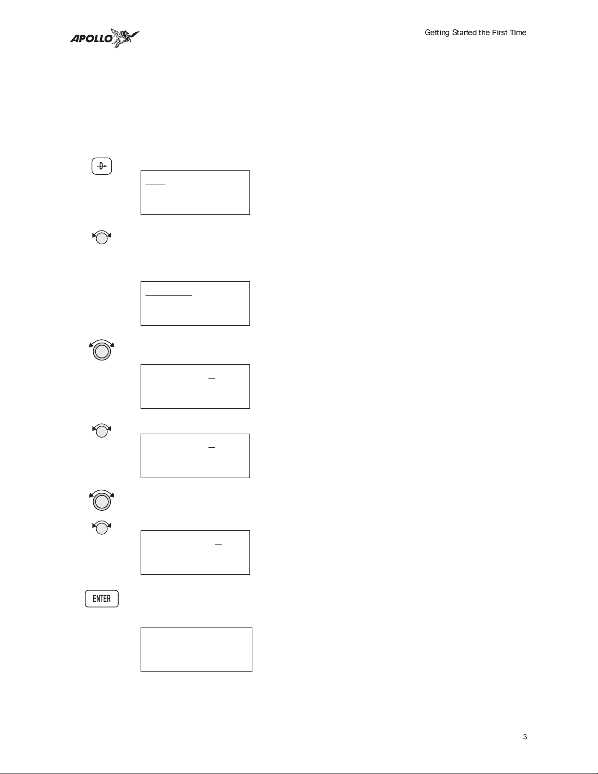
Using the Direct-To Function
Pressing Direct-To allows you to quickly make changes to your TO waypoint.
When you press Direct-To, the default waypoint shown will be the current TO
waypoint in the Nav or Flight Plan functions or the waypoint displayed in the
Database or Info functions. See page 14 for more details.
D
1. Press the Direct-To key. The waypoint type will flash.
VOR CVO
SALEM
CITY OR USA
2. Turn the Small knob to select the waypoint type. You may select: AIRPORT,
VOR, NDB, INT, or USER. For instance, with AIRPORT indicated as the type
of destination waypoint, only airports show on the display as you select
identifier characters.
AIRPORT SLE
SALEM
city OR USA
3. Turn the Large knob clockwise (cw) one position to the waypoint identifier.
The first character of the waypoint identifier will flash.
AIRPORT SLE
SALEM
CITY OR USA
4. Turn the Small knob to change the character.
ENTER
AIRPORT HAB
HAMILTON
city AL USA
5. Turn the Large knob to move to each character of the waypoint identifier.
Change the character with the Small knob. Continue using the Large and
Small knobs to select your waypoint.
AIRPORT HIB
HIBBING
city MN USA
6. After selecting the desired waypoint identifier, press ENTER. Your Apollo GX50
will now switch to the Navigation function and show information based on a direct
route from your present position to the Direct-To destination waypoint.
ete aHIO 00:12
“ 0.000
Brg 346 35.2nm·
3
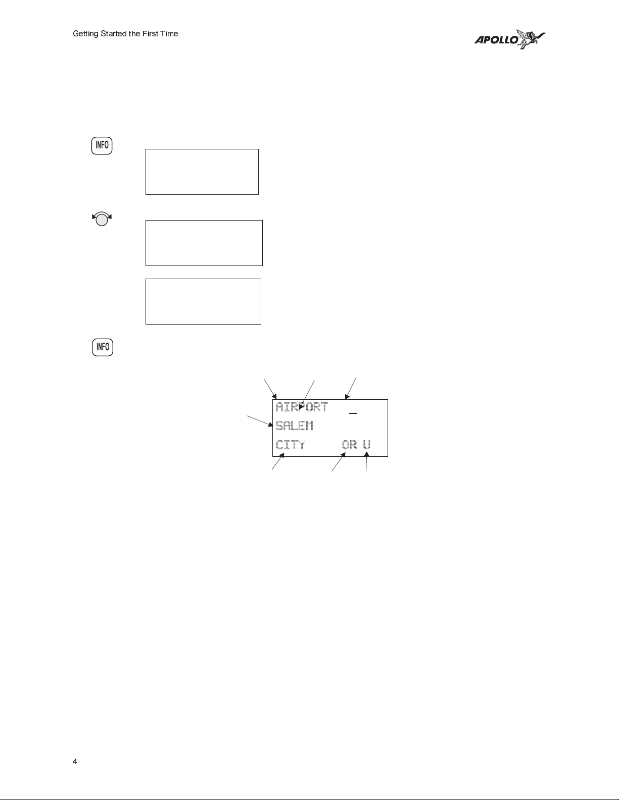
Getting Started the First Time
Waypoint
Information
1. Press INFO to view information about the TO waypoint.
INFO
2. Turn the Small knob to view the available information about the TO waypoint.
3. Press INFO again to return to the previous display.
INFO
The GX50 contains a wealth of information in its database. Pressing the INFO
key will access the information about the destination (TO), or displayed,
waypoint.
HIO AIRPORT
PORTLAND
city OR USA
HIO ATIS 127.65
UNIC 123.00
TWR 119.30
HIO 12 /30
6600ft Hard ILS
Lighted
Waypoint Type
(Airport shown here)
Underline indicates
flashing character
Waypoint
Indentifier
City or Facility
Name
City or Facility
AIRPORT
SLE
SALEM
CITY OR USA
State
Country
4
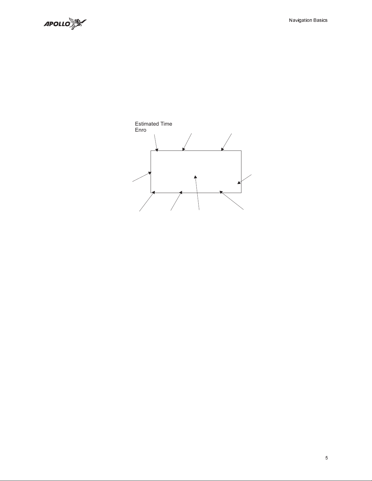
Navigation Basics
Estimated Time En Route (Ete)
ETE is to the current TO (destination) waypoint from your present position based on the
current ground speed. The units shown are in hours and minutes, 00:00 to 99:59. If the
ground speed is less than or equal to 5 knots, the GPS receiver does not have a valid
position, or there is no TO waypoint, the ETE value will be shown as dashes. If there is
no TO waypoint, the TO identifier location will be replaced by dashes.
Navigation Basics
Estimated Time
Enroute Label
ete aEUG 00:16
Distance
Off Track
Bearing Label Range to Destination
1.120
Brg 173 45.5nm“¼·
Bearing Value
Waypoint
Indentifier
Graphic CDI
Indicator
Estimated Time
Enroute Value
º
"Diamond" indicates
more pages can be
selected with the
knob.Small
Waypoint from your
Present Position
Bearing (Brg)
Bearing is the angle from your present position to the TO waypoint. Bearing is shown
from 0 to 359 degrees in one degree increments. Bearing is computed using the magnetic
variation at the Present Position. The Bearing value will be dashed if the FROM or TO
waypoints are blank or the GPS receiver does not have a valid position.
Range (Rge)
The distance from your present position to the TO waypoint. Units can be set as either
nautical miles or kilometers in the Nav Info section of the System functions (see page ).
Nautical mile units are 0.00 to 9.00 nm in 0.01 nm increments, 10.0 to 99.9 nm in 0.1 nm
increments, and 100 to 9999 nm in 1 nm increments. Kilometer units are 0.00 to 99.99
km in 0.01 km increments, 100.0 to 999.9 km in 0.1 km increments, and 1000 to 9999 km
in 1 km increments. The Range value will be dashed if the FROM or TO waypoints are
blank or the GPS receiver does not have a valid position.
5
Navigation Basics
Course Deviation Indicator (CDI) and Distance Off Track
The triangle symbol (
) referenced to a bar graph shows your position relative to being
“
on-course. When the bar graph is to the right of the triangle, you must fly right to return
on-course; the bar graph indicates you are off-course to the left. Fly the aircraft in the
direction of the bar graph to return on-course.
ete aSLE 00:37
#### “ 4.005
Brg 173 42.4nm
CDI Sensitivity = 0.3 nm CDI Sensitivity = 1.0 nm CDI Sensitivity = 5.0 nm
each 7 = 0.01 nm each $ = 0.05 nm each H = 0.24 nm
each 6 = 0.04 nm each z = 0.14 nm each B = 0.71 nm
“ ›››››››
(full scale) = 0.3 nm
“ ¼¼¼¼¼¼¼
(full scale) = 1.0 nm
“ ¥¥¥¥¥¥¥
(full scale) = 5.0 nm
A single dot thickness bar indicates that CDI sensitivity is set to 0.3 nm full scale per
side. The two dot bar indicates a sensitivity of 1.0 nm full scale per side. The three dot
bar indicates a sensitivity of 5.0 nm full scale per side. The manual sensitivity of the CDI
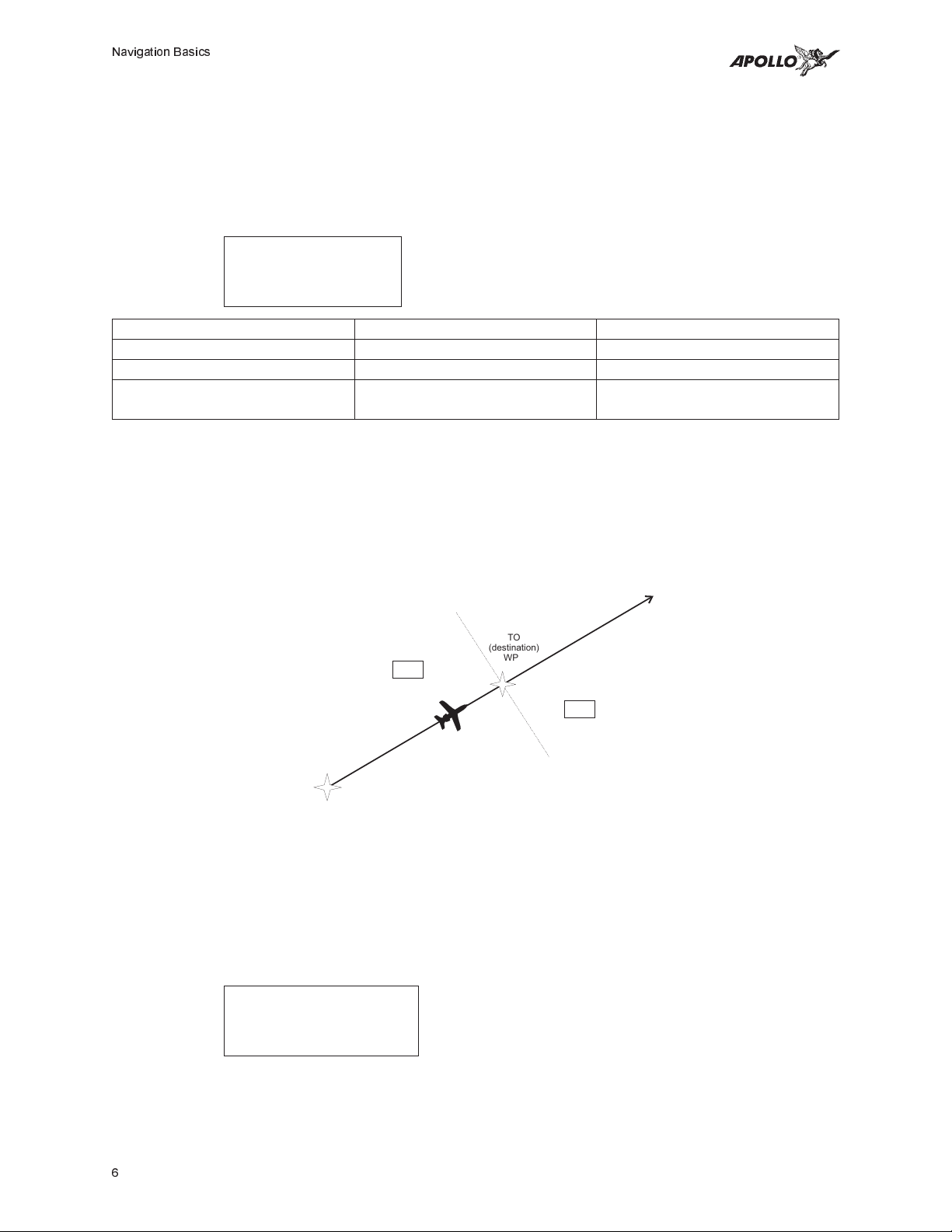
may be set to 0.3, 1.0, or 5.0 nm full scale per side. The triangle symbol is also used as a
TO-FROM indicator. When the triangle is facing up, you are on the “TO” side of the
destination waypoint. When the triangle is facing upside down, you are on the “FROM”
side of the destination waypoint.
To side of destination
waypoint
“
TO
(destination)
WPT
From side of destination
waypoint
”
FROM
(origin)
WPT
The number shown on the edge of the display opposite from the triangle symbol shows
the distance off track. The numbered values of Cross Track Error are in the direction you
are off course. If the numbers are on the left side, fly right to return on course. The
displayed value ranges are: 0.000 to 0.999 nm with 0.001 nm resolution, 1.0 to 9.99 nm
with 0.01 nm resolution, and 10.0 to 99.9 nm with 0.1 nm resolution.
ete aSLE 00:37
0.006 “
Brg 173 42.4nm
If the GPS sensor is not sending a valid position, or the current TO waypoint is blank, the
CDI will display “—Nav Flagged—”.
6
 Loading...