

Page 1

TM
Lock On: Modern Air Combat
TM
Lock On: Air Combat Simulation
Enhanced Manual
Reference Manual
Training Guide
Recognition Guide
Digital Aspirin Ltd & Ubisoft
2003
Copy Number
All content, (including in-game graphics), except where otherwise noted are copyright by
Ubisoft and Digital Aspirin Ltd and cannot be reproduced without expressed written consent. All screenshot images, except where otherwise noted, are copyright Digital Aspirin and
are used under license. Certain images are Public Domain, such as the aircraft recognition
section. Please email info@lomac-manual.com if you believe the manual contains copyrighted material and we will remove and/or label the images accordingly.
Page 2

Page 3

Index
Introduction by Carl C. Norman i
Reference Manual 1
Training Guide 134
Recognition Guide 209
Key Reference 269
Acronyms 276
Brevity Code 278
SAM/AAA Reference Sheets 282
Mission Planning Sheets 284
Page 4

Page 5

Introduction i
Introduction
It is indeed a pleasure to have been asked to write this introduction for what will hopefully
become a trend for flight simulation games.
Our Unique Hobby
Combat Flight Simulation games for have been in existence since the first personal
computers. At one time flight sims were one of the primary entertainment applications for
the personal computer. Those of us that enjoy these products share a love of several
genres, be it the military, flying, speed, or the fine details and procedure of aviation
brought to our screens. Whatever the reason, we all share a common interest in
something that requires patience and skill as well as an understanding of the principals of
flight and aerial combat. We are a unique group of enthusiasts. Instead of wanting a game
that is easy to figure out and simple to operate, we demand and marvel at the complexity
and fidelity of air combat. We are the “Armchair Fighter Pilots” who want to sample a bit of
the thrill of strapping ourselves to a jet that is going to go into harm’s way.
Our Hobby Abandoned
Being unique has a real disadvantage. We are a niche market in an overall population that
craves instant gratification and reward. Alas, our niche community has been abandoned
by the traditional market for video games. The big money can now be found in first-person
shoot ‘em ups, “Pop Culture” licensed titles, and “simulations” that model our
interpersonal relationships. The video game industry has “gone Hollywood” and there is
little room in this financial juggernaut for the detail and high-fidelity that we desire. Video
games are now played on your television with a console box that is easy to use and simple
to configure. While I have nothing against the world of console video games, their
popularity has pushed our hobby off the shelves. Combat fight simulations are not dead,
but they are no longer a genre that is supported by the software industry. Fortunately
publishers like Ubi Soft have supported products like
flight simulation developed by our friends at 1C: Maddox Games who are also located in
Moscow
)
and, of course,
Lock On
IL-2 Sturmovik
(an excellent WWII
The Community
The combat flight simulation community is a strange bunch. Some of the most loyal and
dedicated users of any product can be found in our midst. Many of these people
participate online in the various community forums and product websites. It is an
international crowd with users from all over the globe sharing their passion and
experiences. The majority of these people are friendly and will go out of their way to help
out a fellow flight sim enthusiast. I’m pleased to have made friends all over the world
through my participation online in the flight simulation community.
Unfortunately, we have our dark side as well. While the majority of users are helpful and
willing to assist anyone showing an interest in our hobby, there are also those that show
incredible amounts of intolerance and snobbery. These types are easy to spot in the online
community. Like most human endeavours, there are always a few bad apples. They are to
be avoided if possible. You’ll recognize them immediately should you encounter them
online.
Page 6

Introduction ii
But fear not brave user! The community remains active and vibrant. You can always count
on the majority of online users to give you the answers to your questions and provide you
with the latest information about our hobby. There is also an enormous amount of
creativity online in the form of humor, third-party enhancements, and new missions. It is
well worth your time to spend some time online with this bunch. A good place to start is
the General Forum at www.lo-mac.com.
History of Lock On
Back in 1994 an entertainment software company called Strategic Simulations, Inc. (SSI),
well known for its line of wargames and fantasy role-playing games, was purchased by
Mindscape, Inc. A gentleman named Jim Mackonochie, who was a Vice President for
Mindscape, was able to enter into an agreement with a gentleman named Nick Grey. Nick
is one of the managing directors of The Fighter Collection (TFC), which operates with a
software development studio named Eagle Dynamics. Eagle is based in Moscow and at
the time had a prototype simulation depicting the Su-27 Flanker jet fighter. This product
became
Su-27 Flanker
and was published in 1995.
Lock On
u-27 Flanker
S
the flight sim community to combat aircraft flown by Russia. The staff at Eagle Dynamics
is a very talented and dedicated group of professionals.
I was fortunate enough to have been a newly hired Producer at SSI when the
product was started. The opportunity to work on this project was something I jumped on
immediately. I was working with the fine folks at Eagle Dynamics and my counter-parts at
the Mindscape UK office. Following the release of this first
created an add on product for
product upgrade to Version 1.5.
The sequel
product, we went on to create a major upgrade to
This upgrade would be sold online and would add the MiG-29 as a user flyable aircraft. We
also upgraded and enhanced the overall simulation by fixing some problems and adding
new features.
Lock On
Su-25 Frogfoot attack jet. Our original plan was to dovetail the development effort for the
Flanker 2.5 upgrade into the process to create the
planning for this next Flanker product Mindscape and SSI went through a corporate
acquisition by The Learning Company. This was to be the first of several additional
corporate buyouts and mergers. At the time I was an Executive Producer with SSI in
charge of Combat Simulations.
is the third product in a generation of combat flight simulations that started with
and was followed by
Flanker 2.0. T
he
Flanker
series of products introduced
Su-27 Flanker
Su-27 Flanker
Flanker 2.0
began as a proposed add on product to
was released in 1999 by SSI. As with the original
which included new missions and a major
Flanker
Flanker 2.0
Flanker 2.0
that we called
that would feature the Russian
Su-25 Frogfoot
product we soon
Su-27 Flanker
Flanker 2.5
product. During the early
.
We saw an opportunity to expand our original plans for a new
Western attack jet, the A-10 Thunderbolt II affectionately known as the “Warthog”. At the
time another large publisher of combat flight simulations had cancelled their plans to
feature the Warthog in a product. I must admit at this point that my personal interest in the
Warthog was a major factor in my going the distance to get this aircraft included in the
product. I have always had an interest for the A-10 and wanted it in our simulation very
much. We obtained approval to proceed with including this unique and very popular
combat aircraft into our plans.
Flanker
product by adding a
Page 7

Introduction iii
The decision was made to create a sequel product instead of a mere add on. This new
product would feature the Frogfoot and Warthog and would be called
course there would be a few more corporate adventures and The Learning Company was
soon purchased by Mattel and we became a new publishing and development organization
known as Mattel Interactive. The scope of the product increased at this time by the
inclusion of a Western counter-part to the Su-27. Thus, the F-15C Eagle joined the ranks as
another flyable aircraft in the product.
Flanker: Attack
. Of
At the very end of our development efforts on the
group was again questionable as Mattel was selling off the assets of Mattel Interactive. We
were up for sale with no idea what would happen to our future products. This state of
being would become a familiar one as we were soon sold to a holding company which
helped maintain our existence but had plans to parcel off the assets of the former Mattel
Interactive/Learning Company.
Once
release the 2.5 upgrade for free over the Internet to ensure that the upgrade reached the
users who had purchased
following the release of the
former Mattel Interactive/Learning Company was sold to Ubi Soft Entertainment.
Each one of these corporate acquisitions and changes in ownership resulted in a process of
evaluation to determine which products would continue and which ones would be
cancelled. This resulted in major delays to the products we were working on at the time to
include all the combat simulations. Some products were cancelled; others were cancelled
and then resurrected. Fortunately,
Lock On
more accessible to new users without taking away the more realistic aspects that veteran
users desired. Of course all of this only resulted in further delays.
Flanker 2.5
was finished we were still in a state of limbo. We came to decision to
Flanker 2.0
Flanker 2.5
in case we were forced to shut down. Several weeks
upgrade the entertainment product group of the
Flanker: Attack
. We added some new features to include the ability to scale the product to make it
Flanker 2.5
survived but it now had a new name –
upgrade the future of our
In late 2002 I left Ubi Soft and began working directly with The Fighter Collection and Eagle
Dynamics. I was pleased to be able to concentrate my efforts on the genre and product
line that I loved. Our product had suffered many delays and yet all of knew that it had
great potential. We also knew that there was little competition for this type of product as
modern air combat simulations were not being supported by the industry. We believed
then and we still believe now that we have a product that would be popular.
This Manual
My association with Mr. Nic Cole began in the late Summer of 2003 when he inquired on
the official Lock On forums about the possibility of producing a hard copy manual for Lock
On. I contacted him and lent my support for such an effort. I had been suggesting that a
hard copy manual for Lock On be made available for separate purchase by the publisher so
I was very pleased to see an effort from the community take form.
The trend in the entertainment software industry has been to eliminate hard copy manuals
and move to smaller standard packaging for software products. The documentation for
most products being sold now consists of a small “get started” pamphlet and a more
extensive manual in “electronic format” on the game disk. This arrangement works fairly
well for 99% of the games being published. It does not work well for a detailed and
complex product like a combat flight simulation. I have always been an advocate of rich
and detailed documentation for the products I’ve worked on, but the costs and resources
for this type of manual were no longer something that the publishing arm was interested in
devoting to a niche line of products.
Page 8

Introduction iv
Through his persistence and some backing by a few of us that really believed in the
concept of a third-party manual effort, Nic Cole was able to convince Ubi Soft that this
manual was a viable option. An agreement was soon reached. Nic began to gather
content and enlist the help of several of us in the Lock On community to assist him in
getting the manual together. We at Eagle Dynamics were delighted at the prospect of a
more detailed hard copy manual. That you are now reading this is proof that a grass
roots effort by dedicated and talented members of the flight sim community can achieve
great things.
The Future
As I write this introduction we are in the final days of development for Lock On. We are
testing a Release Candidate as I type. It’s been a long process to get it finished and we are
very proud of our work. What about the future?
We see great potential for follow on products in the form of new aircraft to fly and new
missions. We have several proposals for such products and we hope that they are
forthcoming. There are also new combat simulation products on our drawing board that
we hope to bring to you in the future. The future of all these products depends on the
success of Lock On. The potential for these types of third-party produced manuals
depends on you, the members of community. Please help promote this manual to your
peers. Let them know about it and urge them to support Nic and his efforts. This will
ensure that we have this type of documentation for future products.
Much Appreciation
Those of us at TFC/Eagle Dynamics would like to thank several people who really made a
difference. Mark “Shepski” Shepheard and Andrew “Swing Kid” Pavacic were
instrumental in their assistance. We owe our dedicated external Beta Testing crew our
thanks for the many hours of dedicated support. They and many others too numerous to
mention here are listed in the credits and several of them have been with us since our first
product. “Gentleman Jim” Mackonochie continues to be an invaluable ally and friend and
we are grateful for his constant support.
T
hanks also to our friend and colleague Matt Wagner at Ubi Soft for his hard work and
dedicated efforts. Special thanks to Nic Cole for making this manual possible. We wish
him much success in this venture and hope that it is the start of something that continues
for our community and his success.
I would also like to express my deep personal appreciation for my associates Igor Tishin,
Jim Mackonochie, and Nick Grey. I have always been blessed to have been working with
people whom I can call friend. I am also proud to have worked with the talented staff of
Eagle Dynamics. Their hard work and skill is appreciated by all of us.
Kind Regards,
Carl C. Norman
Executive Producer
The Fighter Collection / Eagle Dynamics
Page 9

Manual Credits
Nic Cole – Editor
Mark Shepheard – Training Section Editor
Lynn Gosley – Binder Design and Build Consultant
Quality Assurance & Clearance
Matt Wagner – Ubisoft
Charlie Barrett – Ubisoft
Carl Norman – Eagle Dynamics / The Fighter Collection
Special Thanks Go To:
Introduction v
The entire www.lo-mac.com forum moderators and members for their
welcome input and encouragement.
Chris Bergeron
Christopher Halpin
Terry Reinhart at Virtual Flight Productions
Carl Norman (again)
For their proof reading skills and mastery of the English language
Sarah Berridge at Ubisoft for putting up with our requests for graphics and
text at such short notice.
Nic Cole
Digital Aspirin
Sheffield
November 2003
Page 10
Introduction vi
Lock On Credits
Eagle Dynamics
M A N A G E M E N T
Nick Grey
Project Director,
Director of The Fighter Collection
Igor Tishin
Project Development Manager,
Director of Eagle Dynamics, Russia
Andrey Chizh
Assistant Development & QA Manager
Carl Norman
Executive Producer & Consultant
D E S I G N E R S
Vladimir Trifonov
Terrain
Vladimir Titov
Terrain
Marina Kurdjukova
Terrain
Vladislav Kuprin
Cockpits, GUI
Alexander Drannikov
Planes
Timur Cygankov
Ships, ground vehicles
Page 11

Introduction vii
Yury Shubin
Planes
Alexander Porozov
Planes
Vyacheslav Bogdanov
Graphics effects
Denis Poznyakov
Graphics effects
P R O G R A M M E R S
Valery Blazhnov
Lead Programmer
Vyacheslav Patutinsky
AI Planes
Igor Krylov
SAMs, Ships, Ground Vehicles
Evgeny Dovgopoly
Mission Editor
Igor Loginov
GUI, Mission Editor
Alexey Kravetsky
GUI, Mission Editor
Alexey Vakhov
Mission Editor
Alexander Alexeev
GUI
Anton Trutce
Avionics, weapon systems
Vladimir Feofanov
Flight dynamics
Maxim Zelensky
AI Planes, Flight Dynamics
Alexander Matveev
Input, Sound
Sergey Chistov
Track IR, Sound
Grigory Yakushev
Graphics
Timur Ivanov
Graphics
Yury Uralsky
Graphics
Dmitry Sultanov
Graphics
Dmitry Zhukov
Graphics
Maxim Porshnev
Objects Animation
Dmitry Robustov
Terrain
Dmitry Baikov
Internet game, Installer, GUI
Sergey Gurchev
LAN game, Track Recording
Dmitry Illarionov
MAP
T E C H N I C A L S U P P O R T
German Lutchak
Internet & Network maintenance
Andrey Solomykin
Flight dynamics research
Dmitry Moskalenko
Aerodynamics calculations
Denis Panchuk
Aerodynamics calculations
Alexander Komarov
Lead Tester
Vitaly Nikityanin
Optimisation
Page 12

Introduction viii
U B I S O F T
CEO:
Yves Guillemot
International Production Director:
Christine Burgess-Quemard
International Content Director:
Serge Hascoet
L O C A L I Z A T I O N
Worldwide Localization Manager:
Coralie Martin
Localization Project Manager:
Loic Jacolin
P R O D U C T I O N
Florence Alibert
EMEA Group Manager:
Gabrielle Zagoury
EMEA Brand Manager:
Yannick Spagna
International Marketing Team:
Sylvaine Gomez
Andreas Balfanz
Doug Mc Conckey
Christian Born
Javier Montoro
Pim Hofmeester
Nick Wong
Soren Lass
Yannick Theler
Bertrand Chaverot
Vanessa Leclercq
Zhou Hui Bo
VP of product development:
Bret Berry
Executive Producer:
Tony Van
Producer:
Matt Wagner
Associate Producer:
Marc Fish
Data Management International Service:
Guenaele Mendroux
David Picco
Benoit Maury-Bouet
M A R K E T I N G
US Marketing Director:
Tony Kee
US Group Manager:
Karen Conroe
US Brand Managers:
Tena Lawry
Sarah Berridge
EMEA Marketing Director:
P U B L I C R E L A T I O N S
US PR Manager:
Clint Hayashi
T E S T
QA Manager:
Eric Tremblay
Assistant Manager:
Eric Audette
Lead Tester:
Emmanuel-Yvan Ofoe
Testers:
Alain Chenier
Allen Tremblay
Antoine Drouin
Antoine Thisdale
Eric St-Jean
Frederic Laporte
Louis-Phillipe Brissette
Marc Brouillette
Marc-Andre Proulx
Martin Shank
Martin Tavernier
Mathieu Larin
Mathieu Laurin
Page 13

Introduction ix
Pascal Gauthier
Patrice Cote
Pierre Boyer
Compatibility Test:
David Levesque
Jason Alleyne
External Beta Testers:
Oscar Garcia Minguillan
Jose Benito
Francisco de Ascanio
Carlos Garcia Pineiro
Jim Campisi
Jeff Streeter
Gene Buckle
Leonardo Rogic
Goran Ivaz
Robert Borjesson
Juan Andres Hermoso Franco
Guillaume Leleve
Manuel Silveira
Dan Crenshaw
James Rhodes
Moodie Coretti
Chad Matthew Griffin
Michael Scampini
Lou Mayers
Pascual Malonda
Ivan San Primitivo
Alejandro Lorenzo Gallego
Francesc Basullas
Domingo Silanes
Jose Luis Barrero
Jose Ma Catena
Santiago Cerezo
Fernando Fernandez de Benito
Luis Rivas
Roberto Seoane
Ian Boys
Andrew Peter Pavacic
James Hallows
Chris Picco
Aaron Watson
Igor Harlukov
Anton Stepanov
Arkady Lalayants
Denis Chumachenko
Alexander Saigushkin
Alexey Egorov
Danila Pyatkin
Kirill Dzyuba
Vladimir Vorobiev
Alexander Tulin
Alexey Larin
Vagan Grigoryan
Sergey Vertelev
Alexey Prokopchuk
Igor Anisimov
Andrey Serov
Mikhail Sapronov
Alexander Gorbachenko
Ruslan Ilyin
G A M E M A N U A L
Reference Manual:
Tom Basham
S O U N D
Music:
Marshall Crutcher - Perfect Score
Voice recordings:
Charles DeVries Multimedia
S P E C I A L T H A N K S
Thomas Desaveines
for aircraft textures
David Moratilla
for aircraft textures
Eric Johnson
for aircraft textures
Frederic Bourges
for aircraft textures
Troy A. Fortmann
for F-15C consultation
Steve Davies
for F-15C consultation
Edward Burke
for A-10A consultation
Christopher Andreychik
for A-10A consultation
Andy Bush
for A-10A consultation
Joe Hodges
Page 14

Introduction x
for A-10A consultation
Glenn Davis
for military aircraft consultaion
Sergey Trukhan
for Su-25 and Su-27 consultation
Alexander Degtyaryov
for MiG-29 and Su-27 consultation
Daniil Tuseev
for MiG-29 and Su-27 consultation
Nikolay Isaev
for military consultation
Andrew Peter Pavacic
for single missions
and Pilot Log Book consultation
Jan Slegers
for Pilot Log Book consultation
Michael Larsen
for Pilot Log Book consultation
Manuel Fossa
for Pilot Log Book consultation
George Gachaleishvili
for Pilot Log Book consultation
Roy van Versendaal
for Pilot Log Book consultation
Francisco de Ascanio de la Vega
for Pilot Log Book consultation
Ertugrul Ozmen
for Pilot Log Book consultation
Dominik Merk
for Pilot Log Book consultation
Chris Janssens
for Pilot Log Book consultation
Yuri Yashnev
for Pilot Log Book consultation
Mark Shepheard
for training and single missions
Jean-Francis Tetreault, Martin Asnong
for CD protection
Halstead York - NaturalPoint
for TrackIR support
Justin Cooney - ATI
for Development Support
The Forum Moderators and Community
Members at the Official Lock On Forums
Jim Mackonochie
for constant support and Business
Development
Page 15

Introduction xi
Printed Manual Errata
Page 5. Starting the game. A “Show Replay” (SHOW)” button has been added to the
Navigation Bar on the Main Menu. Once selected, you can use the browser menu to select
Track Files. Once selected, press the Start button to begin playing the Demo track.
Page 5. Starting the game. A “Network Play (NTW)” button has been added to the
Navigation Bar on the Main Menu. This allows you to directly access the Network play
menus from the Main Menu.
Page 6. Starting the game. The Back/Fwd Button has been removed from the Main Menu.
Page 9. Graphics. We suggest setting VISIB RNG and SCENES to High and WATER to Very
High if you have top-end computer.
Page 9. Graphics. An option to toggle civilian road and rail traffic on and off had been
added to the Graphics settings. From the CIV TRAFF button, you can select Yes or No.
Page 9. Graphics. An option to toggle the advanced haze effect as been added to the
Graphics settings. From the HAZE button, you can choose Basic or Advanced.
Page 9. Graphics. As option to choose water detail level has been added to the Graphics
settings. From the WATER button, you can choose Low, Medium, High, or Very High.
Page 9. Graphics. An option to disable engine heat blur has been added to the Graphics
settings. From the HEAT BLR button, you can select On or Off. Note that game
smoothness can at times be negatively impacted if Heat Blur and FSAA are used
simultaneously.
Page 9. Graphics. The FREQ selection has been removed.
Page 10. Audio. If you feel the engine and other cockpit sounds are too quiet, you can use
the COCKPIT slider to increase the volume. You can also increase the ENGINES level to
make the engine sound louder in the cockpit.
Page 10. Audio. “Betty in Russian” has been changed to “Russian Voices.” This is
because you can now hear all radio communications in Russian when flying a Russian
aircraft. If you select the German MiG-29A, the Betty voice will be in German.
Page 11 and 45. Difficulty. Two additional buttons have been added to the My Plane box.
The G-EFFECTS button allows you to disable black-outs and red-outs when under extreme
G. The PADLOCK button allows you to enable or disable the use of the padlock option.
Page 11 and 46. Difficulty. The AWACS view has been renamed the MAP view.
Page 11. Difficulty. Within the Simplification box is a button entitled SET GLOBAL. When
this button is ON, the player’s difficulty settings and the Scene setting for Graphics will be
used for all missions. If however the button is not on, the difficulty and scene settings will
be used when the mission was created.
Page 11. Difficulty. When simplification is changed between imperial and metric, this only
applies to measurements used in the Mission Editor. It does not apply to the flight portion
of the game.
Page 16

Introduction xii
Page 12. Cockpit. The G-Effects setting has been moved to the Difficulty page.
Page 18. Multiplayer. After pressing the NTW button, a window that allows you choose
either a LAN or Internet game will be displayed now. You must make this decision before
preceded to Host or Join a multiplayer game.
Page 19. Multiplayer. Protocol section has been removed from LAN network connection
options.
Page 19. Multiplayer. The Ubi.com button only applies to an Internet game. This button
has been removed from the LAN screen.
Page 18. Multiplayer. The multiplayer description in only accurate for when LAN play is
selected. Internet play uses an entirely new system of connection. When you enter an
Internet game, there will be a two-position dial near the top of the screen. One setting is
labeled Player and the other Connect.
When set to Player, you can enter your name in the NAME field. Press the enter key once
you have typed in your name.
When set to Connect, you can enter your Host or Client connection properties. If Network
Settings button is set to SERVER, then you are acting as the Host and you can determine
PORT number, connection speed, and password. You can also set global setting such as
session title, maximum number of players, and game mode in the Game Settings screen.
If set to Client, you can enter the SERVER IP number and the required password if needed.
Once the SERVER and CLIENTS have entered the required data, they can press the START
key to proceed.
After the SERVER presses the START key, they will be brought to the OPEN mission screen.
After selecting the desired mission, press the MAP key to return to the Internet interface.
Once all players have reached the Join Game screen, they can select their coalition. If no
planes are available in a coalition, the JOIN box will be greyed out. Upon selecting a valid
coalition, press the SELECT button in the top / left portion of the screen to select an aircraft.
Simply click on the aircraft you wish in the Select Plane list. If you wish to change
coalitions, you can click the Coalitions button on the top menu bar.
Once players have selected their aircraft, the FLY button can be pressed to start the
mission. Note that each player must press the FLY button in order to enter the mission.
Page 22. Multiplayer. It is not possible for clients to in-flight refuel during multiplayer
games.
Page 22. Multiplayer. Only a single player can be assigned to take off from the Kuznetsov
aircraft carrier. Adding more than one aircraft will cause over-lapping.
Page 22. Multiplayer. When flying an Internet game, each player must be assigned an
individual Group when creating the mission. You cannot assigned players to separate
Flights within a Group.
Page 22. Training. Advanced Training has been renamed Top Gun.
Page 17

Introduction xiii
Page 22. Training. Select the EXIT button in the lower / left portion of the screen to exit
the Training screen.
Page 22. Training. In order to avoid problems with the training missions, please mind the
following:
- Resolution to 1024x768
-Cockpit view angle set to 60(default)
-Mouseview off
-Mirrors off
-Russian HUD setting
-Do not press any key but "S" to pause and un-pause while viewing
Page 25. Log Book. The pull down menu to view general statistics has been removed.
Page 26. Log Book. To exit the Log Book, press the Exit button in the lower / left portion of
the screen.
Page 29. Easy Radar. When setting the display mode to ALL, all ground, surface, and
naval units will be displayed on the screen.
Page 30. Mission Editor. From the File selection on the Menu Bar, Merge is also available.
This allows two separate missions to be combined into a single mission.
Page 30. Mission Editor. From the View selection on the Menu Bar, Crimean View has
been changed to Actual Size view. Additionally, Object View and Region View have been
removed.
Page 30. Mission Editor. From the File selection on the Menu Bar, Record AVI has been
added. After selecting a track file, this option can be enabled and allow the player to
convert a track file into an AVI video. To create an AVI file, please follow these steps:
1- From the Mission Editor, select the desired Track file you wish to convert to an
AVI file.
2- Once selected, select RECORD AVI from the File pull down.
3- A new dialog screen will be presented in which you can select Start and End time
of recording, the compression Codec and quality level, the name you wish to save
the AVI as, and the frame rate you wish the AVI to play back as.
Once you have made your selections, press the Start button. Lock On will then replay the
Track file frame by frame until completion. Note that this can be a long process of the
recording length or frame rates have been set high.
After the video had been recorded, the sound pass will automatically be recorded. This will
play back in real time, but you will only hear the mission being played out. For proper AVI
sound recording, ensure you have WAV as your Windows sound recording device.
Page 30. Mission Editor. From the File selection on the Menu Bar, Loop track can be
selected to continually loop the selected track file.
Page 44. Mission Editor. Regarding cloud cover, when the Density is set to 5 or higher, the
precipitation drop down becomes active. Selections include None, Rain, and
Thunderstorm. If however the Season is set to Winter, the precipitation options will be
None, Snow, and Snow-storm
.
Page 18

Introduction xiv
Page 45. Mission Editor. Creating a Campaign. Creating a user-created campaign is a
simple process that uses the fundamentals of creating a single mission within the Mission
Editor. To get started, enter the Mission Editor and press the CAMP button on the left
portion of the screen.
You will now be presented with the Campaign creator / editor. To create a new campaign,
follow these steps:
1- Select the countries that will take part in the two coalitions. From the Coalitions
button at the top of the screen, place at least one country in the Red and Blue
coalitions. Press OK when complete.
2- In the top Title box, enter the title of the campaign you are about to create.
3- Each mission is composed of a generated stage that you create. In the Stage box,
enter the name of the first stage in the Title box. In the Description box, enter the
text briefing that the player will read.
4- Create the stage as you would a normal single mission. However, all the static
objects you place in the first stage will automatically be carried over to later
missions.
5- When you are ready to create the next stage in the campaign, forward the stage
number to 2 and create you next mission. You can keep adding stages this way
until you have all the stages you wish in the mission.
6- To enter the text that the player will read when he or she has finished the
campaign; select the Results button and enter the campaign debriefing text.
TROUBLESHOOTING & TIPS
Increasing frame rate and performance
It’s always a good idea to defragment your drive for better performance. Use the Windows
Disk Defragmenter in Accessories/System Tools to defragment your drive.
Ensure that you have the very latest drivers for you video card. You can usually obtain
updated drivers on the support website of your card’s manufacturer. The manufactures of
the more popular video cards often update their drive sets.
Ensure that you have DirectX 8.1 or higher installed on your system. DirectX 9 is included
as part of the Lock On installation routine. The setup for DirectX 9 is located on the Lock
On CD. Many of the “MX” type of cards are older video chips that are use more memory
and are then marketed as newer cards, but many of them do not support 8.1 or higher.
Older video cards MAY run Lock On but without all the effects and the performance will be
questionable. Your video card MUST support DirectX 8.1 or higher. NOTE: Having the
correct version of DirectX installed on your system alone is NOT the answer. Your card
MUST also be compliant with 8.1 or higher. Older cards will most likely NOT meet this
requirement.
Shut down programs running in the background (Virus Scanners, Firewalls, etc.) Zone
Alarm is known to cause problems when trying to use the Options menu as reported by
several Lock On Demo users. If you choose to run other applications in the background
you WILL have a lower performance with Lock On. There are several utility programs such
as Enditall and others you can obtain on the Internet that can assist you in shutting down
other applications.
Page 19

Introduction xv
Lock On will run slower if you have all the graphics and effects settings on their highest
settings. This is particularly noticeable with minimum spec computers and hardware.
Your “mileage” may vary, but to get all the effects and have good performance you will
need top of the line equipment. Lock On can be run at lower settings and still be a very
enjoyable simulation experience, but the high end and the future of hardware were primary
considerations when we designed this product and its graphics effects.
Performance will also be affected by the size and content of missions. Large missions with
many vehicles, missiles, aircraft, and radars will have a noticeable affect on performance
and frame rates. Try adjusting the settings in the Options – Graphics screen to optimize for
your best performance for your hardware.
There are quite a few different options for graphics and cockpit settings in Lock On the
more of them you use and the higher the quality you select then the lower your
performance will be when running the program. While we would like to provide you with
an optimum settings profile, it is impossible to give a profile that will be optimum for all
the many different hardware configurations that users possess. You are going to have to
experiment with your individual settings to see what works best for you and what options
you feel are worth the hit in performance. As each of us have our own personal
preferences for graphics and effects, these aspects only add to the difficulty in our
providing a standard profile. Again, your preferences and personal tastes will have to be
factored into how you set up the features in Lock On.
The settings for WATER, VISABLE RANGE, and COLOR have a big impact on frame rate.
The WATER effects are a big frame killer even if you are not flying over water and have the
setting on high, your performance will be lower. Set WATER to Low if you do not have a
high performance system and/or video card.
VISABLE RANGE will also take a lot of your system’s performance. Unless you are using a
high resolution, there really is no big difference between the Medium and High settings for
this option. Medium appears to be optimum. Your results may differ depending upon
your hardware.
The HEAT BLUR effect is NOT compatible with your video card anti-aliasing features turned
on and will create a conflict that will greatly affect performance and frame rate. If you want
HEAT BLUR effects you need to turn off your anti-aliasing settings. Note: The HEAT BLUR
effects do not appear for all aircraft (A-10 for example) and will not appear for aircraft if
they are travelling at high speeds.
The COLOR setting should really be set to 16 bit as the advantages of 32 bit are only for the
very top end video cards. The advantage of 32 bit will most likely be noticeable with video
cards that will be hitting the market in the near future. For now it is recommended that you
stick with 16 bit. If you do use 32 bit, ensure that your Windows Desktop is also set for 32
bit.
Cockpit Mirrors are nice to have, but they can rob you of performance. They are not
essential, particularly for air-to-ground. Turn them off unless you really feel that you need
them. You can also lower their resolution to save on performance.
Page 20

Introduction xvi
Joysticks, Throttles, Rudders, and other devices
You may need to manually adjust your joystick, throttle, and rudders using the Options –
Input menu.
The default settings for Lock On may not match your particular input devices. Go to the
Options section and set the select knob to INPUT in the upper right hand corner of the
Options screen.
In the upper left hand corner there is a toggle switch showing BUTTONS or AXIS, click on
this so that AXIS is selected and then select the pull-down box window so that your
particular joystick is selected instead of KEYBOARD or MOUSE.
In the BUTTONS MAP text box below on the left will be a list of input areas and their
corresponding inputs (PITCH, ROLL, RUDDER, THRUST, etc.) and their respective axis or
rotator. To ensure your equipment is configured properly select each one and then hit the
CHANGE button to upper right. A CAUTION dialog box will appear with a blank entry for
an Axis input. When this box appears move the appropriate device you want to set. The
proper axis or rotator will appear in the text box. Hit OK and you have set the device
properly in Lock On.
NOTE: This section also provides you the ability to configure dual or split throttles to
control two-engine aircraft if you have such an input device.
In the RESPONSES section of the INPUT screen there is a graph showing the response
profile for each device. It is recommended that you select your RUDDER in BUTTONS MAP
and then flip the switch in RESPONSES from SLIDER to AXIS. This will display the
response curve for your RUDDER.
Often the rudder input devices continue to “pull” to one side. This will cause your aircraft
to roll or yaw to one side. Configuring your rudders with a bit of a “dead space” will
prevent your aircraft from rolling or pulling to one side. Do this by selecting the RUDDER
in the BUTTONS MAP area and then moving the D-ZONE slider a small amount to the left.
You will notice a flat line appear in the middle of the response curve. This will create a
dead space at the centre of your rudder that will prevent rudder inputs while your rudder is
in the center position.
It is also recommended that you increase the curve by placing the SHIFT slider in the
middle position of the slider giving the rudders a smooth response curve on both sides.
There is also a selection on this screen that will allow you reverse (invert) the directions of
your input devices.
Trim and Control
Several of the aircraft, the MiG-29 in particular MUST be constantly trimmed or your
control inputs will not be as effective. Read the section on trim and consult the appropriate
Tutorial Mission to learn how to trim the aircraft. ALT-T will neutralize your trim settings.
NOTE: Airspeed changes also affect trim settings. Be sure to adjust trim after coming out
of Autopilot.
Page 21

Introduction xvii
Audio Adjustments
If you are having choppy or distorted sound, turn Hardware Acceleration OFF in your
DirectX Sound Settings. To do this, run the DirectX Diagnostics Tool
(C:\WINDOWS\system32\dxdiag.exe), select the SOUND tab, and turn off Hardware
Acceleration with the slider. Even if you do not have distorted sounds, many users of the
Demo have reported better performance with Hardware Acceleration turned off.
If you want more ambient sounds in the cockpit you will need to adjust your audio volume
settings in the Options – Sound screen. Adjust the sliders for the various sound effects to
the levels you prefer. If you like to hear the engines and gun fire from the cockpit then you
should increase the ENGINES and COCKPIT sliders to higher. 100% for COCKPIT will give
you both engines and gun sounds.
As with the graphics settings, the volume of the various sounds in Lock On is an individual
taste. You need to experiment with the settings to obtain the sound levels you desire.
Engaging Targets with Weapons
Familiarize yourself with the proper way to configure your aircraft for combat modes. The
weapons will not fire unless you configure your aircraft to the proper combat mode. The
default mode is Navigation when you first start a mission. The weapons will not fire in Nav
mode.
Taking Screenshots and Recording Videos
Screenshots can be made by hitting the PrtScn (Print Screen) button. Each time you hit
this button a screenshot will be created and saved to the Lock On Screenshots subdirectory
with a sequential naming convention. If you wish to remove the information bar for
exterior views hit the “Y” key twice to turn off the bar. Hitting “Y” again will toggle the bar
back on.
Key Input Changes
1-Cockpit camera discrete steps have been implemented with Ctrl - Keypad 1-9 or Ctrl Joystick hat. Alt-Z toggles between snap modes (to return or not to return camera tacitly).
The discrete steps are configurable in the Config/View/View.cfg file.
2- Ctrl-Keypad 5 action has been changed to Alt-Keypad 5 for F11 view.
3- Shift-F11 trains/cars toggle has been added for Ctrl-F12 view.
Page 22

Introduction xviii
This page has been left intentionally blank
Page 23

INSTRUCTION MANUAL
CONTENTS
Aircraft Introduction . . . . . . . . . . . . . . . . . . . . . . . . . . . 2
Aircraft Cockpits . . . . . . . . . . . . . . . . . . . . . . . . . . . . . . 6
Heads-Up Display Modes . . . . . . . . . . . . . . . . . . . . . 30
Sensors . . . . . . . . . . . . . . . . . . . . . . . . . . . . . . . . . . . .68
Radar Warning Receivers . . . . . . . . . . . . . . . . . . . . . . 76
Air-to-Air Missiles . . . . . . . . . . . . . . . . . . . . . . . . . . . . 82
Air-to-Ground Weapons . . . . . . . . . . . . . . . . . . . . . . . 97
Ground School . . . . . . . . . . . . . . . . . . . . . . . . . . . . . 108
Primary Flight School . . . . . . . . . . . . . . . . . . . . . . . . 112
Air Combat Basics . . . . . . . . . . . . . . . . . . . . . . . . . . . 115
Weapon Usage . . . . . . . . . . . . . . . . . . . . . . . . . . . . . 129
Page 24

2 Aircraft Introduction
AIRCRAFT INTRODUCTION
The old adage, “Use the right tool for the job,” applies to air combat as much as
carpentry. Aircraft missions, such as air superiority, close air support, deep strike,
etc., generally have conflicting requirements. Heavy armor that protects a pilot
while engaging an enemy AAA site is a serious disadvantage in a dogfight.
Success in the air requires a thorough understanding of each aircraft’s strengths
and weaknesses. The following section identifies each aircraft flyable by the player
and summarizes its combat role.
1.1 F-15C “Eagle”
The F-15C “Eagle” has often been labeled the greatest fighter aircraft in the world.
Designed to counter the exaggerated capabilities of the Soviet MiG-25 “Foxbat,”
the F-15 has been the backbone of U.S. air defense for three decades. The F-15C,
equipped with improved avionics and weapons over the original F-15A, has scored
over 100 air-to-air victories in the service of Israel, Saudi Arabia, and the U.S.
without suffering any losses.
The F-15C rules the Beyond Visual Range arena (BVR). No slouch in a dogfight, the
F-15C excels at finding targets, positively identifying them as hostile, and engaging
them with AIM-120 AMRAAM and AIM-7M missiles before the enemy can
respond.
The Eagle is somewhat restricted in the close-in dogfight. The AIM-9 Sidewinder, a
reliable weapon that has soldiered on since the 1960’s, does not have the high offboresight capability of recent Russian heat-seeking missiles. Eagle drivers should
generally favor the higher-speed “energy fight” in favor of the low-speed turning
duel, especially against nimble adversaries.
Length: 63’ 9”
Height: 18’ 8”
Wingspan: 42’ 10”
Speed: Mach 2.5+ at sea level
Ceiling: 65,000’
Max. Takeoff Weight: 68,000 lbs
1.2 A-10A “Thunderbolt II”
Very few address this aircraft by its given name of “Thunderbolt II.” Instead, its
unusual appearance earned it the moniker “Warthog,” and often simply “the Hog.”
Designed as a Close Air Support (CAS) platform to counter the massive quantities
of Soviet armor during the Cold War, the Hog is heavily armored and carries an
impressive weapon load, including a deadly 30mm anti-armor cannon. Efforts to
retire the A-10 from active duty began gaining momentum, but fell by the wayside
after the aircraft’s stellar performance during the 1991 Gulf War and the 2003
Operation Iraqi Freedom.
The A-10 was intended to fly low, using the terrain to mask its presence from
enemy Surface-to-Air Missiles (SAMs). Low flying, however, places the aircraft in
the heart of the Anti-Aircraft Artillery (AAA) engagement zone. Therefore, the
aircraft is heavily armored, including a “titanium bathtub” which surrounds the
pilot. When the threat of SAMs has been reduced, the A-10 generally flies
Page 25

Aircraft Introduction 3
missions at medium altitudes, placing it safely out of the reach of AAA guns.
The sub-sonic A-10 can carry AIM-9 Sidewinders for self-defense, but should avoid
dogfighting. It carries an impressive air-to-ground weapon load, but lacks the
power for a sustained fight against a dedicated air-to-air platform. When
confronted by an enemy fighter, the Hog pilot should use the A-10’s impressive
turn rate capability to point the nose (and the dreaded 30mm cannon) at the
attacker. When the attacker overshoots, unload and extend until the attacker
makes another pass, and then use another maximum-rate turn to point the nose
back at the adversary.
Length: 53’ 4”
Height: 14’ 8”
Wingspan: 57’ 6”
Speed: Mach 0.56
Ceiling: 45,000’
Max. Takeoff Weight: 51,000 lbs
1.3 Su-25 “Frogfoot”
The Su-25 Frogfoot bears little resemblance to the U.S. A-10, but was designed for
a very similar Close Air Support (CAS) ground-attack mission. The Su-25 was built
to operate near the battlefront from rough, “unimproved” airstrips, and can carry a
kit with tools, spare parts, auxiliary power supply, a pump for manual refueling,
and other “self-deployment” supplies. It carries a wide variety of weapons for
missions, including anti-radar, runway denial, and tank killing.
The fortified cockpit and armored canopy helps protect the pilot from AAA and
small-arms fire while engaging targets at low altitude. Flying low, the Su-25 hunts
down mobile targets, pops up, delivers its weapons, and dives back behind the
terrain. The Frogfoot may arguably be the most powerful ground-attack aircraft in
Eastern inventories.
The Su-25 is not intended for dogfighting, though. Its primary defense against
patrolling flights is simple avoidance. When engaged, the Su-25 should operate at
extremely low altitude, which hampers enemy fighters’ ability to dive toward it.
Using available terrain, the pilot should turn to face oncoming threats.
Length: 50’ 11”
Height: 15’ 9”
Wingspan: 47’ 11”
Speed: Mach 0.8 at sea level
Ceiling: 22,965’
Max. Takeoff Weight: 38,800 lbs
1.4 Su-27 “Flanker B”
The Su-27 Flanker and its descendants are some of the most impressive and
capable fighter aircraft in the world, designed to beat the vaunted F-15. Born in the
waning years of the Cold War, the Flanker did not have an easy life. The initial design
suffered serious problems. Then, the breakup of the Soviet Union hindered its
deployment, denying it the opportunity to prove itself as the world’s greatest aircraft.
Page 26

4 Aircraft Introduction
The Su-27 is tailored for air-to-air combat, not air-to-ground. Armed with the R-27
(AA-10) Alamo missiles, the Flanker has an impressive BVR capability. Meanwhile,
the helmet-mounted sight and the high off-boresight R-73 (AA-11) Archer heatseeking missile, coupled with the Su-27’s high thrust and sustained turn capability
give the aircraft a powerful edge in a knife fight. High-AOA maneuvering helps the
pilot point his weapons at the enemy. Finally, its large fuel capacity keeps it in the
fight well after most Western aircraft are running on fumes. It carries as many as
ten air-to-air missiles, giving it an impressive “punch.”
Detractors criticize the Su-27’s avionics and cockpit layout, citing limited ability to
track/engage multiple targets, high reliance on GCI control, and high pilot
workload, but its passive Electro-Optical System (EOS) lets it find and engage
targets without any radar signals (which can warn the target). Debate continues
on whether high-AOA maneuvers (such as tail slides and the famed “Cobra”) are
useful combat tactics or merely impressive air-show routines.
Length: 71’ 11”
Height: 19’ 5”
Wingspan: 48’ 2”
Speed: Mach 2.35 at sea level
Ceiling: 59,055’
Max. Takeoff Weight: 72,750 lbs
1.5 Su-33 “Flanker D”
Originally named the Su-27K, this descendant of the Su-27 was specifically
designed to operate from Soviet versions of super aircraft carriers. Equipped with
canards for improved takeoff and landing performance, the first Su-27K made its
maiden flight in 1985. The tail cone was shortened to reduce the risk of tail strike
during high-AOA carrier landings, but also reduced the space available for
defensive countermeasures (including chaff and flare dispensers). Whereas the
Su-27 was tailored as an air-to-air interceptor, the Su-33 is a multi-role aircraft (a
necessity of carrier-based aviation operating far from home bases). The Su-33
retains, to a large extent, the avionics and cockpit of the basic Su-27.
Length: 69’ 6”
Height: 19’ 4”
Wingspan: 48’ 2”
Speed: Mach 1.14+ at sea level
Ceiling: 55,250’
Max. Takeoff Weight: 66,000 lbs
1.6 MiG-29A “Fulcrum A” and MiG-29S “Fulcrum C”
Western observers often conclude, inaccurately, that the Su-27 and MiG-29 were
born of a single design program, which copied the U.S. Navy’s F/A-18, no less.
Indeed, the Su-27 and MiG-29 look quite similar, and some observers cannot
readily tell the two aircraft apart, despite the MiG-29 being substantially shorter
than the Su-27. Both the Su-27 and MiG-29 design teams reportedly worked with
common research data and drew common design conclusions. The MiG-29 was
much more widely exported than the Su-27, serving in many Warsaw Pact air
Page 27

Aircraft Introduction 5
forces, several of which have since joined NATO (bringing their Soviet-made MiG29s with them).
The MiG-29 originally shared most of its avionics suite with the Su-27 (including
the radar, the Electro-Optical System (EOS), and the helmet-mounted sight), but
was designed as a short-range fighter, not an interceptor. The EOS lets the
Fulcrum search for, track, and engage targets without emitting tell-tale radar
signals. Being smaller, it doesn’t carry as many missiles as the Su-27, but its highAOA maneuverability, coupled with the R-73 (AA-11) Archer high off-boresight,
heat-seeking missile, and helmet-mounted sight makes the MiG-29 a deadly
dogfighter. The slow-speed turning fight is the MiG-29’s preferred arena where it
can use its high-AOA capability to point its weapons at a floundering target. The
newer MiG-29C includes the medium-range R-77 (AA-12) Adder missile and an
internal radar jamming system.
As with the Su-27, critics cited weak avionics and poor cockpit design as
weaknesses of the MiG-29A. The later MiG-29S (Fulcrum C), though, incorporated
numerous improvements, including better defensive countermeasures and
increased fuel capacity. The MiG-29 reportedly requires a significant amount of
maintenance, especially the engines. German MiG-29As (inherited from the East
when Germany was re-unified) have had their engine performance “tuned down”
somewhat to preserve engine lifespan. Obtaining spare parts continues to be a
concern for former Warsaw Pact nations.
Russian forces in LOMAC employ the MiG-29A and MiG-29S, while German
forces in NATO operate only the MiG-29A.
Length: 56’ 10”
Height: 15’ 6”
Wingspan: 37’ 3”
Speed: Mach 2.3 at sea level
Ceiling: 55,775’
Max. Takeoff Weight: 40,785 lbs
Page 28
6 Aircraft Cockpits
AIRCRAFT COCKPITS
Each aircraft’s cockpit is tailored for the role it performs. Although all cockpits
share certain instruments, such as an airspeed indicator, an attitude indicator,
engine indicators, etc., cockpit design philosophies have changed dramatically over
the years. Furthermore, Eastern and Western aircraft designers often take different
approaches to solving common problems. As a result, cockpit layout varies greatly
from aircraft to aircraft.
In this chapter, we’ll examine each aircraft’s cockpit and instrumentation.
You’ll need to familiarize yourself with the cockpit layout for each aircraft type
you intend to fly.
2.1. F-15C Eagle Cockpit
Although the F-15C Eagle retains a nominal air-to-ground capability, it is strictly an
air-to-air superiority fighter today. Consequently, its cockpit is tailored around the
radar display and threat warning display, which are situated just below the HUD.
The lower section of the instrument panel focuses on aircraft attitude, engines,
and storage management.
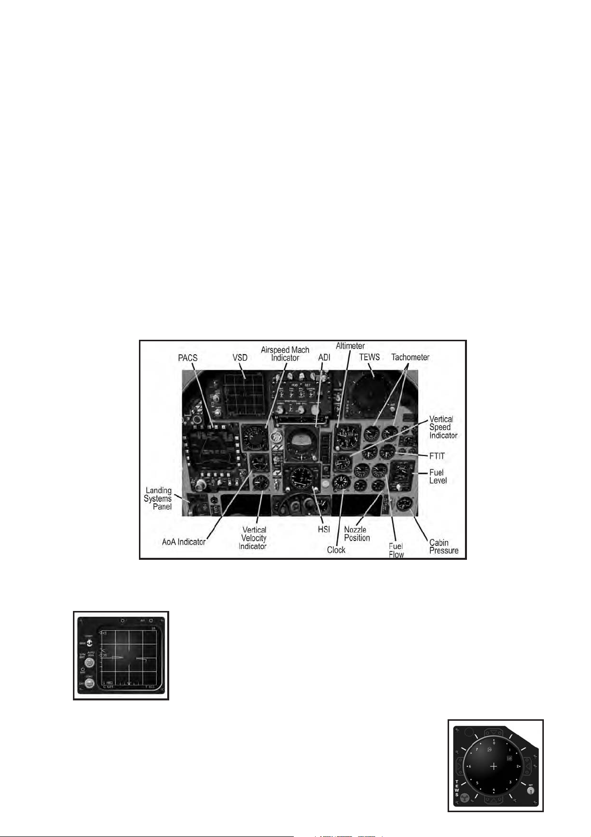
The F-15C Cockpit
2.101 Vertical Situation Display (VSD)
The Vertical Situation Display (VSD), otherwise known as the
“radar display,” dominates the instrument panel’s upper-left
corner. The VSD shows a top-down view of the airspace ahead
of the aircraft, highlighting target aircraft detected by the radar.
Full details of radar operation and VSD symbology appear in the
“Sensors” chapter.
The VSD
2.102 Tactical Electronic Warfare System
(TEWS)
The Tactical Electronic Warfare System (TEWS), located in the
upper right of the instrument panel, detects radar emissions
(from other aircraft, surface-to-air missile launchers, etc.). It
The TEWS
Page 29
Aircraft Cockpits 7
categorizes the information it detects and displays clues about the direction and
type of emitter. Full usage and symbology details appear in the “Radar Warning
Receivers” chapter.
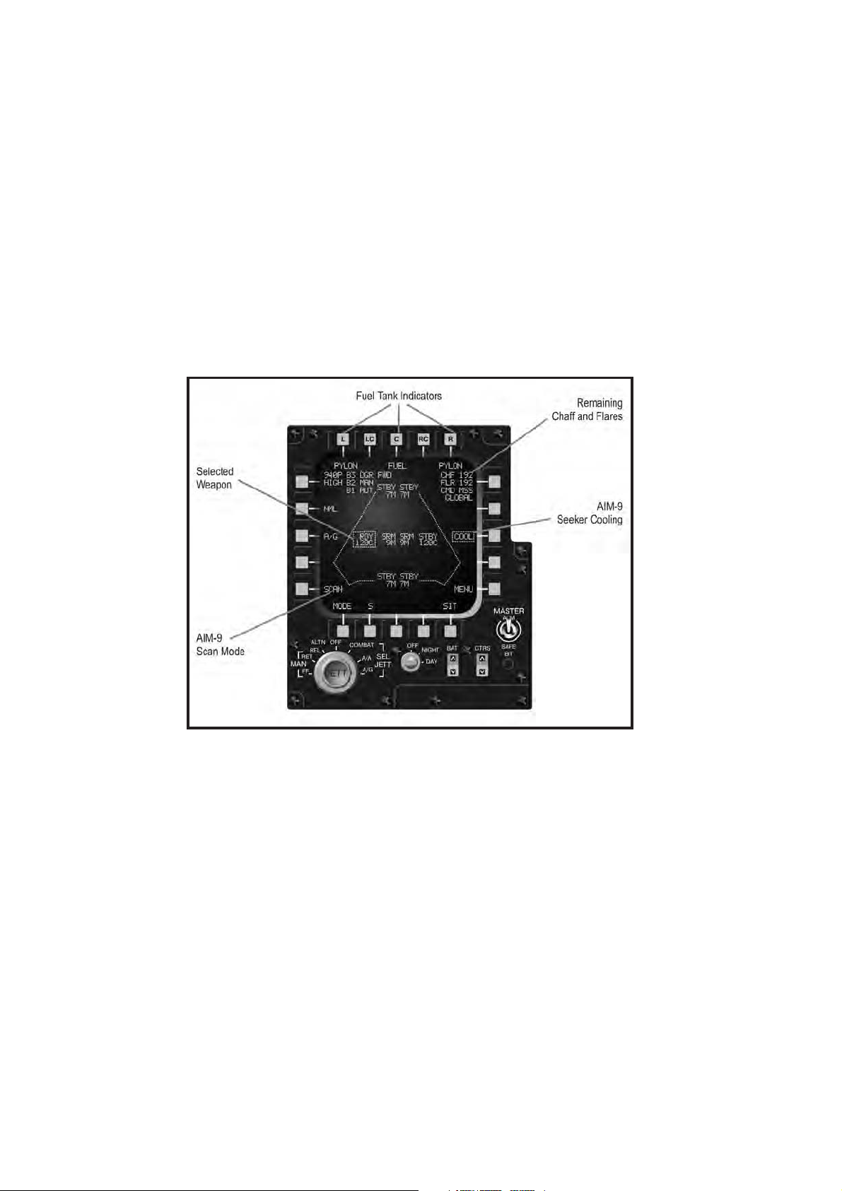
2.103 Programmable Armament Control System (PACS)
The Programmable Armament Control System (PACS), located in the lower left of
the instrument panel, is a multipurpose display that provides storage (fuel,
weapons, chaff, and flares) management.
The top edge of the PACS display shows the number of loaded external fuel
tanks. The positions L, C, and R indicate the status of the left, center, and
right pylons, respectively. When a fuel tank is loaded, the word “FUEL”
appears beneath the pylon indicator. When a tank is not loaded, the word
“PYLON” appears.
Fuel Tank Indicators
The left side of the PACS display shows two indicators. The uppermost button
shows the current firing rate of the 20 mm cannon. HIGH indicates 6,000 rounds
per minute; LOW indicates 4,000 rounds per minute. The number directly below
the rate of fire indicates the quantity of 20 mm rounds remaining. When fired, the
counter decrements in units of 10.
The SCAN indicator in the bottom-left corner will be highlighted with a box when
an AIM-9 missile is selected and operating in SCAN mode. See the “Weapon
Usage” chapter for full details on using SCAN mode.
The right side of the PACS display indicates the defensive stores (chaff and flares)
remaining, along with weapons status. The CHF and FLR displays in the upper
right indicate the number of chaff and flares, respectively. The F-15C can carry up
to 120 chaff rounds and up to 60 flares.
The COOL indicator along the right edge of the PACS display indicates the overall
weapons status. With the Master Arm switch in the ARM position, a box appears
around the word “COOL,” indicating weapons are ready. The box disappears when
the Master Arm switch is in the SAFE position.
The center of the PACS display shows the loaded weapons and their status. There
are eight weapon stations, four on the fuselage and two on each wing. Air-to-air
Page 30
8 Aircraft Cockpits
missiles appear in two categories: AIM-9 variants are classified as “Short-Range
Missiles” (SRM), while AIM-7 and AIM-120 variants are classified as “MediumRange Missiles” (MRM). The status for each station shows two lines based on
the selected weapon type:
• When an MRM is selected: RDY appears above the selected weapon. STBY
appears above all other medium-range missiles. SRM appears above all shortrange missiles.
• When an SRM is selected: RDY appears above the selected weapon. STBY
appears above all medium-range missiles. SRM appears above all other shortrange missiles.
The following table illustrates the abbreviations used for each missile type:
Abbreviation Missile Range
7M AIM-7M MRM
120C AIM-120 MRM
9M AIM-9M SRM
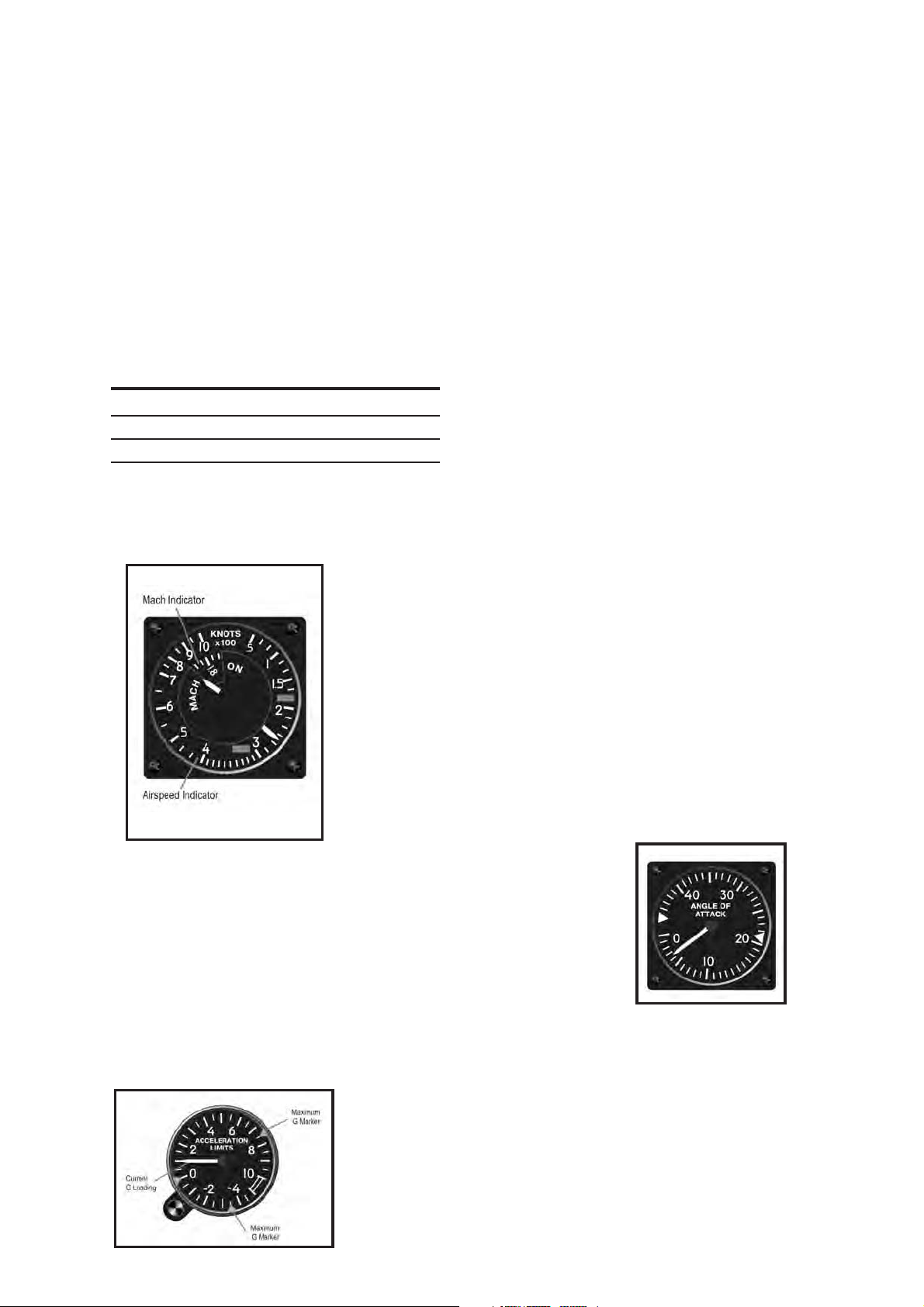
2.104 Airspeed/Mach Indicator
Located next to the PACS, the airspeed/Mach indicator shows the Calibrated
Airspeed (CAS) and Mach number. The fixed airspeed
scale, graduated from 50 to 1000 knots, and a rotating
Mach number scale (synchronized so their correct
relationship is shown at all altitudes) allow a single
pointer to indicate both readings. The Mach number
shows above 200 knots.
Airspeed / Mach Indicator
2.105 AOA Indicator
Located below the airspeed/Mach indicator, the AOA
indicator displays the current Angle Of Attack in units from
0 to 45. The units are calibrated against the F-15C’s normal
flight envelope – a single unit does not equate to a single
degree of pitch. An index mark is set at the approximate
optimum landing approach AOA (20 to 22 units).
AOA Indicator
2.106 Accelerometer
The accelerometer displays instantaneous positive and
negative acceleration G-loads. Markers highlight the
maximum positive and negative G-loads achieved. The
instrument is independent of, and less accurate than,
the G-load displayed on the HUD.
Accelerometer
Page 31

Aircraft Cockpits 9
2.107 Attitude Director Indicator (ADI)
The Attitude Director Indicator (ADI)
dominates the center of the instrument
panel. The rolling attitude sphere displays
the aircraft’s pitch and bank angles. Pitch
markings are graduated in 5-degree
increments. The bank markings are
graduated in 10-degree increments.
During Instrument Landing System (ILS)
approaches, the ILS bank steering
(localizer) and glideslope bars appear in
front of the attitude sphere. During ILS
Longitudinal Aiming Mode Symbology
bottom of the instrument. When not centered, apply rudder toward the needle to
center the indicator.
landings, fly toward the ILS needles.
The turn-and-slip indicator resides at the
2.108 Horizontal Situation Indicator (HSI)
The Horizontal Situation Indicator (HSI)
shows a horizontal, top-down view of
the aircraft superimposed on a
compass. The compass rotates so that
the aircraft heading always appears at
the top of the display. The outer edge
of the compass ring shows the course
arrow, indicating the direction of the
next navigation point.
The course deviation indicator in the
center of the compass illustrates the
intended course relative to the aircraft
in the center of the instrument. During
an ILS landing, the bar corresponds
The HSI
deviation from the localizer beam. Please note, however, that the course deviation
indicator moves the opposite direction of the ILS bank steering bar.
The desired heading is also displayed numerically on the right side of the
instrument. The distance to the destination, in nautical miles, is shown on the left
side of the instrument.
with the bank steering bar, showing
The Altimeter
2.109 Altimeter
The altimeter displays altitude above sea level (MSL) in 20-foot
increments. It consists of a numeric readout in the center with
a clock-like display along the outside edge, which graphically
displays the “hundreds” of feet. In the example shown, the
numeric readout shows an altitude of 29,093 feet. The needle,
therefore, points to 93.
Page 32

10 Aircraft Cockpits
2.110 Vertical Velocity Indicator (VVI)
The Vertical Velocity Indicator (VVI) indicates the aircraft’s rate of
climb (or descent) in thousands of feet per minute. The needle
counts clockwise from zero as the aircraft climbs, and counts
counter-clockwise as the aircraft descends.
The Vertical Velocity Indicator
2.111 Engine Tachometer
This pair of instruments indicates the engine speed as a
percentage of maximum RPM for both the left and right
engines. The red band indicates afterburner.
Engine Tachometers
2.112 Fan Turbine Inlet Temperature (FTIT)
Indicators
FTIT Indicators
Located below the tachometers, this pair of instruments
combines an analog pointer and digital readout. The
temperature is shown in increments of 10 degrees centigrade.
The red band indicates excessive temperature.
2.113 Fuel Flow Indicators
This pair of instruments shows the fuel flow, including
afterburner, for each engine. Flow is measured in pounds per
hour.
Fuel Flow Indicators
2.114 Exhaust Nozzle Position Indicators
Located in the lower right of the instrument panel, this pair of
instruments shows the exhaust nozzle position for each engine.
The display shows the position as a percentage of being
completely open.
Exhaust Nozzle Position Indicators
2.115 Fuel Quantity Indicator
Fuel Quantity Indicator
The fuel quantity indicator shows the remaining
fuel in the internal and external tanks. The needle
in the center of the display shows the internal
fuel, measured in thousands of pounds. Three
numeric indicators show the total fuel remaining
(internal and external), the fuel remaining in the
left wing tank, and the fuel remaining in the right
wing tank. All three displays measure the
remaining fuel in pounds.
Page 33

Aircraft Cockpits 11
2.116 Cabin Pressure Indicator
The cabin pressure indicator shows the current “altitude”
inside the cockpit based on the air pressure in the cabin. In the
event of structural damage, the cabin may lose air pressure,
causing the cabin altitude to increase. If the cabin pressure
altitude climbs above 10,000 feet, descend immediately!
Cabin Pressure Indicator
2.2. A-10A Cockpit
Designed specifically for Close Air Support (CAS) ground attacks, the A-10A
doesn’t carry radar or many of the advanced electronic systems found in other
fighters. It has a much simpler cockpit dominated by navigational and engine
instruments. The sole TV screen shows only images from AGM-65 Maverick
seekers.
The A-10A Cockpit
2.201 TV Monitor
The TV Monitor (TVM) displays the view from the AGM-65
Maverick missile-seeker head. A description of AGM-65 displays
and the targeting process is included in the "Sensors" chapter.
The TV Monitor
2.202 Radar Warning Receiver (RWR)
The A-10’s radar warning system consists of two instruments.
The Radar Warning Receiver (RWR), located in the right side of
the instrument panel, listens for radar emissions (from other
aircraft, surface-to-air missile launchers, etc.). It categorizes the
information it “hears,” displaying clues about the direction and
The RWR
below the HUD, provides additional details about the sources of radar emissions.
Full usage and symbology details appear in the RWR chapter.
source of the emitter. The RWR control indicator, located just
Page 34

12 Aircraft Cockpits
Airspeed / Mach Indicator
2.204 AOA Indicator
Located to the left of the Airspeed Indicator, the AOA
indicator displays the current Angle Of Attack in units from
zero to 30. The units are calibrated against the A-10A’s normal
flight envelope – a single unit does not equate to a single
degree of pitch. An index mark is set at the approximate
AOA Indicator
optimum landing approach AOA (20 units).
2.203 Airspeed Indicator
Located just below the RWR scope, the airspeed
indicator shows Calibrated Airspeed (CAS) from 50 to
500 knots, and reads within 4 knots of the airspeed
displayed on the HUD. The striped needle moves to
show the limiting structural airspeed.
2.205 AOA Indexer
The AOA indexer sits on the canopy railing just left of the
HUD. It displays three indicators comparing the current
AOA with the proper landing approach AOA. When the top
light illuminates, the AOA is either too high or the airspeed
AOA Indexer
is too slow. When the bottom light illuminates, the AOA is
either too low or the airspeed is too high. When the center light illuminates, the
aircraft is maintaining the correct landing AOA. Slight errors are indicated when
the center light illuminates in conjunction with one other light.
2.206 Attitude Director Indicator
(ADI)
The Attitude Director Indicator (ADI) dominates
the center of the instrument panel. The rolling
attitude sphere displays the aircraft’s pitch and
bank angles. Pitch markings are graduated in 5degree increments. The bank markings are
graduated in 10-degree increments. During
The ADI
appear in front of the attitude sphere. During ILS landings, fly toward the ILS
needles.
Instrument Landing System (ILS) approaches, the
ILS bank steering (localizer) and glideslope bars
The turn-and-slip indicator resides at the bottom of the instrument. When not
centered, apply rudder toward the needle to center the indicator.
Page 35

Aircraft Cockpits 13
2.207 Horizontal Situation Indicator (HSI)
The Horizontal Situation Indicator (HSI)
shows a horizontal, top-down view of the
aircraft superimposed on a compass. The
compass rotates so that the aircraft heading
always appears at the top of the display.
The outer edge of the compass ring shows
the course arrow, indicating the direction of
the next navigation point.
The course deviation indicator in the center
of the compass illustrates the intended
course relative to the aircraft in the center
of the instrument. During an ILS landing,
HSI
localizer beam. Please note, however, that the course deviation indicator moves
the opposite direction of the ILS bank steering bar.
the bar corresponds with the bank steering bar, showing deviation from the
The desired heading is also displayed numerically on the right side of the
instrument. The distance to the destination, in nautical miles, is shown on the left
side of the instrument.
2.208 Altimeter
The altimeter displays altitude above sea level (MSL) in 20-foot
increments. It consists of a numeric readout in the center with
a clock-like display along the outside edge, which graphically
displays the “hundreds” of feet.
The Altimeter
2.209 Vertical Velocity Indicator (VVI)
The Vertical Velocity Indicator (VVI) indicates the aircraft’s rate of
climb (or descent) in thousands of feet per minute. The needle
counts clockwise from zero as the aircraft climbs, and counts
counter-clockwise as the aircraft descends.
The Vertical Velocity Indicator
2.210 Accelerometer
The accelerometer displays instantaneous positive and
negative acceleration G-loads. Markers highlight the maximum
positive and negative G-loads achieved.
Accelerometer
2.211 Interstage Turbine Temperature (ITT)
Indicators
This pair of instruments displays the temperature between the
high and low-pressure turbine sections in degrees C.
Interstage Turbine Temperature Indicators
Page 36

14 Aircraft Cockpits
2.212 Engine Core Speed Indicator
This pair of instruments indicates the compressor core speed as
a percentage of maximum RPM for both the left and right
engines.
Engine Core Speed Indicator
2.213 Engine Oil Pressure Indicator
This pair of instruments indicates the engine oil pressure reading
in psi. If pressure drops below 27.5 psi, the engine oil pressure
caution light illuminates.
Engine Oil Pressure
2.214 Fan Speed Indicator
This pair of instruments indicates the engine speed as a
percentage of maximum RPM for both the left and right engines.
Engine fan speed is the primary indicator of thrust being
generated by the A-10A’s TF-34 engines.
Fan Speed Indicator
h Engine fan speed provides the best indication of thrust being
generated in the A-10A.
2.215 Fuel Flow Indicators
This pair of instruments shows the fuel flow for each engine.
Flow is measured in pounds per hour.
Fuel Flow Indicators
2.216 Flaps Indicator
The flaps indicator shows the position of the flaps.
Flaps Indicator
2.217 Brake Indicator
The brake indicator shows the position of the speed brake.
Brake Indicator
2.218 Fuel Quantity Indicator
The fuel quantity indicator shows the remaining fuel in the
internal and external tanks. The digital readout shows internal
fuel remaining. The left and right pointers indicate fuel remaining
in the left and right tanks, respectively.
Fuel quantity indicator
Page 37

Aircraft Cockpits 15
2.219 Armament Control Panel
The armament control panel
dominates the lower left
side of the instrument panel,
showing the quantity and
status of each of the A-10A’s
eleven hardpoints. Each
hardpoint is represented by
a square of four lights.
The two upper lights in each
square represent the
quantity of weapons (or
jamming pods) on that
hardpoint. If both upper
green lights are lit, there are
two or more weapons on
that hardpoint. If only one
upper green light is lit, there is only one weapon on that hardpoint. When all
weapons on the hardpoint are exhausted, the upper lights turn off and the red
light on the bottom row illuminates.
Armament Control Panel
The green light in the lower row indicates the “active” or selected hardpoint.
Cycling through available weapons causes the green light in the lower row to
move from hardpoint to hardpoint.
2.220 Ripple Quantity Indicator
hAutomatically releasing multiple bombs with a single press of the
release button is called “rippling.”
The Ripple Quantity indicator shows the number of bombs that will be
released per drop.
2.221 Ripple Interval
The Ripple Interval indicator indicates the spacing in milliseconds times ten
between each bomb release. For example, “50” would equate to 500
milliseconds, or 0.5 seconds.
2.222 Cannon Rate Switch
The Cannon Rate switch selects between the high (60 rounds per second) and
low (30 rounds per second) rates of fire for the 30mm cannon.
2.223 Master Arm Switch
The Master Arm switch enables ARM and disables SAFE in the weapons
system. The switch should be in the SAFE position during takeoff, landing, and
flying over friendly territory. Switch to ARM to enable the weapons when
entering hostile airspace.
Page 38

16 Aircraft Cockpits
2.3. Su-25 Frogfoot Cockpit
The Su-25 cockpit is relatively simple, dominated by a series of analog gauges.
In addition, most instruments are the same as (or very similar to) Su-27 and
MiG-29 cockpits.
Landing System Signal Panel
The Su-25 Cockpit
2.301 Indicated Airspeed ( IAS) Indicator
The IAS indicator shows the aircraft’s indicated airspeed (IAS).
The scale ranges from 0 to 800 km/h.
IAS Indicator
2.302 Landing System Signal Panel
The landing system signal panel shows the deployment
status of the landing gear, flaps, Leading Edge Flaps (LEF),
and speed brakes. The red light in the center illuminates
when any of the landing gear is not locked in the position of
the landing gear handle (up or down). The light flashes if one
or more landing gear is locked up but the handle is down, or
if the LEF are down but the handle is up.
2.303 Combined AOA/G-Meter
The combined AOA/G-meter simultaneously displays
the aircraft’s angle of attack and current g-load. The
pointer on the left shows the current AOA in degrees.
The long needle on the right side of the instrument
shows the current g-load.
Combined AOA/G-Meter
2.304 Attitude Director Indicator (ADI)
The ADI simultaneously shows current flight attitude and course guidance
information. The numeric tape in the center shows the aircraft’s current pitch and
bank angle. The horizontal lines remain parallel with the horizon at all times. The
Page 39

Aircraft Cockpits 17
turn-and-slip indicator at the bottom indicates the current sideslip. As always, apply
rudder toward the sliding ball (also called “stepping on the ball”) to center it.
h“Step on the ball” in the turn-and-slip indicator (apply rudder toward
it) to center it and correct sideslip.
The horizontal Pitch Steering Bar in the center of the instrument indicates the
correct pitch angle to reach the next waypoint. Likewise, the Course Steering Bar
leans left or right, indicating the correct course to the next waypoint. When both
bars are centered, the aircraft is on course.
During landings, the W-shaped
glideslope deviation indicator and
course deviation indicator
provide Instrument Landing
System (ILS) direction. If either
channel of the ILS system has
failed, the appropriate OFF light
illuminates. During automatic
landing approaches, the
appearance of either light
indicates an automatic level-off
by the flight control system.
ADI
2.305 Horizontal Situation
Indicator (HSI)
The Horizontal Situation Indicator (HSI)
provides a horizontal view of the aircraft
with respect to the navigation course. The
compass card rotates such that the correct
heading is always displayed at the very top.
The course pointer shows the desired
heading, while the bearing pointer points
HSI
directly toward the next waypoint. The
range counter indicates the distance in
kilometers to the next steer point while the bearing counter provides a numeric
readout of the desired heading. ILS localizer and glideslope bars are located within
the center of the compass.
2.306 Vertical Velocity
Indicator (VVI)
The needle moves along the left edge of the
Vertical Velocity Indicator (VVI), indicating the
aircraft’s current rate of climb or descent. A
turn-and-slip indicator in the center provides
backup should the ADI malfunction. The turn
needle in the center leans toward the
direction of the turn, but does not provide
accurate rate-of-turn information.
VVI
Page 40

18 Aircraft Cockpits
2.307 Radar Altimeter
The radar altimeter shows the aircraft’s current Altitude above
Ground Level (AGL), from 0 to 1,000 meters. It does not
indicate altitude when above 1,000 meters.
Radar Altimeter
2.308 Engine RPM Indicator
The engine RPM indicator shows the current speed of both
engines as a percentage of maximum RPM.
Engine RPM Indicator
2.309 Fuel Quantity Indicator
The fuel quantity indicator shows the amount of fuel remaining
onboard, from 0 to 10 tons. The white tape shows the total fuel
quantity.
RHAW Display Panel
Fuel Quantity Indicator
2.310 EGT Indicators
The Exhaust Gas Temperature (EGT) indicators show the
exhaust temperature from 200 degrees C to 1,000 degrees C.
EGT
2.311 Radar Homing And Warning
(RHAW) Display Panel
The Radar Homing And Warning (RHAW) panel indicates
the direction and source of detected radar emitters. The
Aircraft symbol represents your position; the lights
around it indicate the bearing to the emitter. The six
lights along the bottom indicate the radar type. See the
"Radar Warning Receivers" chapter for additional details.
Page 41

Aircraft Cockpits 19
Weapons Display 2.312
In the rightmost side of the weapons console, there are two small windows
displaying cyrillic letters. These letters identify the type of weapons available in the
currently selected pylons:
• HPC
• YP
• B
• BP
• Blac
Pylons #2 & #9
selected and ready
(green lights). Weapon
of choice: rockets
(HPC). Below "HPC" it
reads "BPY" meaning
the cannon is
operational.
: Rockets
: Missiles (either AG or AA)
: Bombs
Y: Cannon
k and white stripes: no cannon rounds left
Pylons #3 & #8
selected. #3 is not
green because it is
carrying an ECM pod,
not a weapon. Pylon 8
carries a missile (YP).
Pylons #4 & #7
selected. Weapon of
choice: missiles (YP). As
you can see, we are
moving inwards through
the pylons.
Pylons #5 and #6
selected. #6 is not
green because it is
carrying a fuel tank. 5
carries a bomb (b).
Selecting the cannon as
the active weapon is
indicated by the label
(BPY). In the bottom
window there is a "K"
meaning we have
between 1/2 and a full
load of ammo rounds.
As we fire the cannon,
available rounds will
eventually get below
1/2. This is shown by
the label "1/2". If we
keep firing, the next
label will be "1/4". When
no more rounds are left
there will appear a black
and white striped label.
Page 42

20 Aircraft Cockpits
2.313 ECM Light
Before engaging hostile forces it is a good idea to
switch on our ECM pod. A green light will appear
on the right console to inform us that we are
emitting jamming noise.
2.314 Heads-Up Display (HUD)
On the base of the HUD, colored lights indicate sensor and weapon status.
2.315 Weapons Panel
The weapons panel provides indications to inform the pilot of weapon
status and type selected.
Page 43

2.316 Warning Panel
Aircraft Cockpits 21
This series of lights indicates aircraft damage and system indicators.
2.4. Su-27 and Su-33 Flanker Cockpit
The Su-27 and Su-33 cockpits are extremely similar. Although some control panels
differ, the instrumentation is identical between the two aircraft. Furthermore, most
instruments are identical (or very similar) to the MiG-29 and Su-25 cockpits.
IAS Indicator
The Su-27cockpit
2.401 Indicated Airspeed (IAS) Indicator
The IAS indicator shows the aircraft’s Indicated Airspeed (IAS).
The scale ranges from 0 to 1,600 km/h.
Page 44
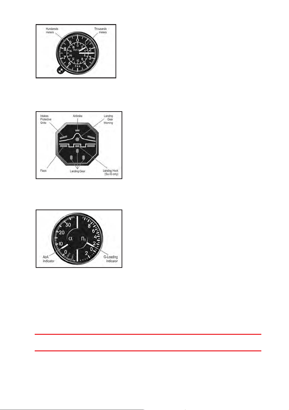
22 Aircraft Cockpits
2.402 Altimeter
The altimeter shows the aircraft’s altitude above
sea level (MSL), from 0 to 25,000 meters. The
inner ring and short needle show the altitude in
thousands of meters. The outer ring and long
needle show it in hundreds of feet. Add the two
readings to obtain the exact altitude.
Altimeter
2.403 Landing System Signal Panel
The landing system signal panel shows the
deployment status of the landing gear, flaps,
Leading Edge Flaps (LEF), and speed brakes. The
red light in the center illuminates when any of
the landing gear is not locked in the position of
the landing gear handle (up or down). The light
flashes if one or more landing gear is locked up
but the handle is down, or if the LEF are down
but the handle is up.
Landing System Signal Panel
2.404 Combined AOA/G-Meter
The combined AOA/G-meter simultaneously
displays the aircraft’s angle of attack and current
G-load. The pointer on the left shows the current
AOA in degrees. The long needle on the right
side of the instrument shows the current G-load.
The small needle indicates the maximum G-load
encountered during the flight.
Combined AOA/G-Meter
2.405 Attitude Director Indicator (ADI)
The ADI simultaneously shows current flight attitude and course guidance
information. The numeric tape in the center shows the aircraft’s current pitch and
bank angle. The horizontal lines remain parallel with the horizon at all times. The
turn-and-slip indicator at the bottom indicates the current sideslip. As always, apply
rudder toward the sliding ball (also called “stepping on the ball”) to center it.
h“Step on the ball” in the turn-and-slip indicator (apply rudder toward
it) to center it and correct sideslip.
The horizontal Pitch Steering Bar in the center of the instrument indicates the
correct pitch angle to reach the next waypoint. Likewise, the Course Steering Bar
leans left or right, indicating the correct course to the next waypoint. When both
bars are centered, the aircraft is on course.
Page 45

Aircraft Cockpits 23
During landings, the W-shaped
glideslope deviation indicator and
course deviation indicator provide
Instrument Landing System (ILS)
direction. If either channel of the ILS
system has failed, the appropriate
OFF light illuminates. During
automatic landing approaches, the
appearance of either light indicates an
automatic level-off by the flight control
system.
ADI
2.406 Horizontal Situation Indicator (HSI)
The Horizontal Situation Indicator (HSI) provides a horizontal view of the aircraft
with respect to the navigation course. The compass card rotates such that the
correct heading is always displayed at the very
top. The course pointer shows the desired
heading, while the bearing pointer points
directly toward the next waypoint. The range
counter indicates the distance in kilometers to
the next steer point, while the bearing counter
provides a numeric readout of the desired
heading. ILS localizer and glideslope bars are
located within the center of the compass.
HSI
VVI
2.407 Vertical Velocity Indicator
(VVI)
The needle moves along the left edge of the
Vertical Velocity Indicator (VVI), indicating the
aircraft’s current rate of climb or descent. A turnand-slip indicator in the center provides backup
should the ADI malfunction. The turn needle in
the center leans toward the direction of the turn,
but does not provide accurate rate-of-turn
information.
2.408 Clock
The clock shows the current time of day.
Clock
Page 46

24 Aircraft Cockpits
2.409 Engine RPM Indicator
The engine RPM indicator shows the current speed of both
engines as a percentage of maximum RPM. The green lights
under the indicator illuminate when the afterburner engages.
Engine RPM Indicator
2.410 Fuel Quantity Indicator
The fuel quantity indicator shows the amount of fuel remaining
onboard, from 0 to 9 tons. The tape in the middle shows the total
fuel quantity.
Fuel Quantity Indicator
2.411 EGT Indicators
The Exhaust Gas Temperature (EGT) indicators show the
exhaust temperature from 200° C to 1,000° C.
EGT
2.412 HDD
The Heads-Down Display (HDD) TV monitor fills the upper right
corner of the instrument panel. The HDD displays the
programmed flight path and steer points, the location of
runways, and the location of targets detected by the radar. See
the “Sensors” chapter for details on HDD usage.
HDD
2.413 Radar Homing And Warning
(RHAW) Display Panel
The Radar Homing And Warning (RHAW) panel
indicates the direction and source of detected
radar emitters. The Aircraft symbol represents your
position; the lights around it indicate the bearing to
the emitter. The six lights along the bottom indicate
the radar type. See the "Radar Warning Receivers"
Chapter for additional details.
RHAW Display Panel
Page 47

2.414 Warning Panel
Aircraft Cockpits 25
This series of lights indicates aircraft damage and system indicators.
2.5. MiG-29 Fulcrum Cockpit
The MiG-29 cockpit is relatively simple, dominated by a series of analog gauges.
The MiG-29A Fulcrum (used by NATO) and MiG-29S Fulcrum C cockpits are
identical. In addition, most instruments are the same as (or very similar to) to Su27 and Su-25 cockpits.
The MiG-29A and MiG-29S Cockpit
Page 48

26 Aircraft Cockpits
2.501 Indicated Airspeed ( IAS) Indicator
The IAS indicator shows the aircraft’s Indicated Airspeed (IAS).
The scale ranges from 0 to 800 kts.
IAS Indicator
2.502 Altimeter
The altimeter shows the aircraft’s altitude above sea level
(MSL), from 0 to 25,000 meters. The inner ring and short
needle show the altitude in thousands of meters. The outer
ring and long needle show it in hundreds of feet. Add the two
readings to obtain the exact altitude.
Altimeter
2.503 Landing System Signal Panel
The landing system signal panel shows the deployment status of the landing gear,
flaps, Leading Edge Flaps (LEF), and speed brakes. The
red light in the center illuminates when any of the landing
gear is not locked in the position of the landing gear
handle (up or down). The light flashes if one or more
landing gear is locked up but the handle is down, or if the
LEF are down but the handle is up.
Landing System Signal Panel
2.504 Combined AOA/G-Meter
The combined AOA/G-meter simultaneously displays the aircraft’s angle of attack
and current g-load. The pointer on the left shows the
current AOA in degrees. The long needle on the right
side of the instrument shows the current g-load. The
small needle indicates the maximum g-load encountered
during the flight.
Combined AOA/G-Meter
2.505 Attitude Director Indicator (ADI)
The ADI simultaneously shows current flight attitude and course guidance
information. The numeric tape in the center shows the aircraft’s current pitch and
bank angle. The horizontal lines remain parallel with the horizon at all times. The
turn-and-slip indicator at the bottom indicates the current sideslip. As always, apply
rudder toward the sliding ball (also called “stepping on the ball”) to center it.
h“Step on the ball” in the turn-and-slip indicator (apply rudder toward
it) to center it and correct sideslip.
The horizontal Pitch Steering Bar in the center of the instrument indicates the
correct pitch angle to reach the next waypoint. Likewise, the Course Steering Bar
leans left or right, indicating the correct course to the next waypoint. When both
bars are centered, the aircraft is on course.
Page 49

Aircraft Cockpits 27
During landings, the W-shaped glideslope
deviation indicator and course deviation
indicator provide Instrument Landing
System (ILS) direction. If either channel of
the ILS system has failed, the appropriate
OFF light illuminates. During automatic
landing approaches, the appearance of
either light indicates an automatic level-off
by the flight control system.
ADI
2.506 Horizontal Situation Indicator (HSI)
The Horizontal Situation Indicator (HSI) provides a horizontal view of the aircraft
with respect to the navigation course. The compass card rotates such that the
correct heading is always displayed at the very top. The course pointer shows the
desired heading while the bearing pointer
points directly toward the next waypoint.
The range counter indicates the distance in
kilometers to the next steer point, while the
bearing counter provides a numeric readout
of the desired heading. ILS localizer and
glideslope bars are located within the center
of the compass.
VVI
HSI
2.507 Vertical Velocity Indicator
(VVI)
The needle moves along the left edge of the
Vertical Velocity Indicator (VVI), indicating the
aircraft’s current rate of climb or descent. A turnand-slip indicator in the center provides backup
should the ADI malfunction. The turn needle in the
center leans toward the direction of the turn, but
does not provide accurate rate-of-turn information.
2.508 Mach Indicator
The Mach indicator shows the aircraft’s current Mach
number.
Mach Indicator
Page 50

28 Aircraft Cockpits
2.509 Clock
The clock shows the current time of day.
Clock
2.510 Radar Altimeter
The radar altimeter shows the aircraft’s current Altitude above
Ground Level (AGL), from 0 to 1,000 meters. It does not
indicate altitude when above 1,000 meters.
Radar Altimeter
2.511 Engine RPM Indicator
The engine RPM indicator shows the current speed of both
engines as a percentage of maximum RPM. Green afterburner
indicators at the far right of the instrument panel indicate when
afterburners are engaged.
Engine RPM Indicator
EGT
2.512 Fuel Quantity Indicator
The fuel quantity indicator shows the amount of fuel remaining
on board, from 0 to 5.5 tons. The tape in the middle shows the
total fuel quantity. The four triangular indicators show the
amount of fuel in the centerline (CL), wing (WING), tank 1, and
tank 3. The four lights illuminate as the respective tanks are
emptied.
Fuel Quantity Indicator
2.513 EGT Indicators
The Exhaust Gas Temperature (EGT) indicators show
the exhaust temperature from 200° C to 1,000° C.
HDD
2.514 HDD
The Heads-Down Display (HDD) TV monitor fills the upper right
corner of the instrument panel. The HDD displays the
programmed flight path and steer points, the location of
runways, and the location of targets detected by the radar. See
the “Sensors” chapter for details on HDD usage.
Page 51

Aircraft Cockpits 29
2.515 Radar Homing and Warning
(RHAW) Display Panel
The Radar Homing And Warning (RHAW) panel indicates
the direction and source of detected radar emitters. The
Aircraft symbol represents your position; the lights
around it indicate the bearing to the emitter. The six lights
along the bottom indicate the radar type. See the "Radar
Warning Receivers" chapter for additional details.
RHAW Display Panel
2.516 Warning Panel
This series of lights indicates aircraft damage and system indicators.
Page 52

30 Heads-Up Display Modes
HEADS-UP DISPLAY MODES
3.1. F-15C Eagle HUD Modes
3.101 Basic HUD Symbology
Several indicators on the F-15C HUD are common to all HUD modes.
Basic HUD Symbology
• The Aircraft symbol, similar to the letter “W,” appears exactly in the center of
the HUD and indicates where the aircraft’s nose is pointing.
• The heading scale appears along the top edge, displaying the heading
rounded to the nearest ten (for example, 270 appears as 27).
• The airspeed scale on the left edge shows the Indicated Airspeed (IAS) in
knots. The airspeed scale does not display values below 150 knots.
• The altitude scale on the right edge shows the aircraft’s altitude above sea
level (MSL) in feet.
• The velocity vector moves through the middle of the HUD, showing the
direction the aircraft is actually moving, which varies from where the aircraft is
heading because of momentum, sideslip, angle of attack, etc.
• The pitch scale appears in the middle of the HUD, centered on the velocity
vector. Primarily, it shows the aircraft’s pitch measured in five-degree
increments. The entire scale moves left and right, however, mirroring the turnand-slip indicator on the ADI. As with the turn-and-slip indicator, to stop
sideslip, apply rudder toward the scale.
3.102 Navigation Mode
As the name implies, navigation mode provides navigation and steering cues.
Basic navigation mode points the way to the next steer point within the
programmed route. ILS mode, on the other hand, provides information required
during landings.
Page 53

Navigation HUD
Heads-Up Display Modes 31
Basic Navigation
The basic navigation mode provides steering cues to the next route steer point. In
addition to the basic HUD scales, navigation mode includes the following
indicators:
• The mode indicator in the lower right of the HUD displays the name of the
selected steer point, followed by the mode name, “NAV.”
• The distance indicator beneath the mode indicator shows the distance (in
nautical miles) to the next steer point.
• The time-to-go indicator, located beneath the distance indicator, shows the
time to the next steer point.
• The aircraft g indicator appears in the lower-left corner of the HUD.
• The integrated flight director appears as a cross on the HUD. It points
toward the next steer point, providing both pitch and bank steering cues. To fly
directly to the next steer point, steer the aircraft until the flight director is
centered in the HUD, directly over the Aircraft symbol.
ILS Mode
When ILS mode is engaged, the HUD displays the following indicators in addition
to the basic navigation indicators:
• The mode indicator in the lower right of the HUD displays the identifier of
the selected steer point, followed by the mode name, “ILSN.”
• The landing gear status indicator appears in the lower-right corner, below the
time-to-go indicator. It shows either GSUP (when the landing gear is raised) or
GDWN (when the gear is lowered).
• The angle-of-attack scale appears on the left side, inside of the airspeed
scale. The caret on the right side of the scale shows the current AOA. The
scale measures AOA in units, not degrees, which range from 0 to 45.
Landings should occur at approximately 22 units of AOA.
• The ILS needles appear just above the aircraft marker, near the center of the
HUD. The horizontal bar represents the desired altitude; the vertical bar
Page 54

32 Heads-Up Display Modes
represents the desired course. As with the ILS bars in the ADI, steer toward
the bars. When the ILS bars are centered, the aircraft is following the proper
approach.
To enter ILS mode, press the 1 key to cycle between enroute navigation and ILS
navigation.
3.103 Gun Mode Steering
The gun mode appears after enabling the internal 20mm cannon. Different
indicators appear depending upon whether a target is radar locked or not. To enter
gun steering mode, you first must be in air-to-air weapons mode and then activate
the gun.
Radar Search Mode
Radar search mode, also called the auto-acquisition mode, displays the basic HUD
indicators plus the following additional fields:
Cannon Search Mode
• The gun reticle appears just below the heading scale. In search mode, the
reticle consists of a 2-mil pipper centered inside a 25-mil segmented circle,
likewise centered within a 50-mil circle. The reticle does not move and
provides no information except to quickly identify that the cannon is enabled.
• Gun information appears in the lower-left corner, replacing the g indicator.
The word “GUN” confirms that the gun is enabled, followed by the number
and type of rounds remaining. “GUN 940 P,” for example, indicates 940
rounds of PGU-38 20mm rounds.
• The Mach indicator appears beneath the gun information, showing the
aircraft’s current Mach number.
• The navigation distance indicator appears in the lower-right corner. It shows
the letter “N” followed by the distance (in nautical miles) to the next steer
point.
This mode is always enabled when the radar is off, or a target has not been locked
on radar.
Radar Tracking LCOS Mode
When the radar tracks a target, the HUD replaces the static reticle with the
Page 55

Heads-Up Display Modes 33
Lead Computing Optical Sight (LCOS) and shows additional information
about the target.
To initiate LCOS mode, you must first activate the radar and then lock the target
by either manually locking the target on radar or flying the gun reticle over the
target. Once the reticle is over the target and within 10 miles, an LCOS mode will
automatically be initiated.
Cannon LCOS Mode
• The gun cross appears just below the heading scale. It shows where rounds
will travel if the aircraft is not maneuvering.
• The target designator box appears over the locked target.
• The range scale appears on the right of the HUD, showing range from 0 to
10 nautical miles. The caret on the left side marks the range to the locked
target. The number next the caret shows the target’s closure rate. Tick marks
indicate the AIM-9 minimum and maximum launch ranges (against a nonmaneuvering target).
• The LCOS gun reticle shows where a round from the cannon will be when
it has traveled the distance to the target and accounts for drop due to gravity.
To ensure a hit, steer the aircraft until the reticle’s center dot overlays the
target designator box.
Additionally, the range bar within the reticle provides a graphical representation of
the range to the locked target. Each tick mark on the reticle represents 1,000 feet
of range, counting clockwise from the 12 o’clock position. The maximum range
cue is located outside the reticle and indicates the maximum effective range of
the cannon. When the range bar passes this cue moving counterclockwise, the
target is within cannon range.
Finally, the lag line extends from the center of the reticle, indicating the pipper is
displaying an error. The longer the lag line, the greater the probable targeting error.
• The range-to-target readout in the lower right of the HUD provides a
redundant display of the range to the target, showing the letter “R” followed
by the range to the locked target.
• Target aspect angle appears beneath the range-to-target readout, measuring
Page 56

34 Heads-Up Display Modes
the angle between the target’s tail and the line of sight to the target. The
letter “R” or “L” appears after the angle, indicating which side of the target is
presented toward the player’s aircraft.
hRemember: Lower aspect angles increase the effectiveness of your
weapons!
3.104 AIM-9
The essential Short-Range Missile (SRM) display symbols provide weapon status
and pursuit course steering. The heat-seeking AIM-9 has a seeker head
completely independent from the radar. The seeker can acquire targets with or
without using the radar. Once the missile is launched, it receives no further
guidance from the launching aircraft.
Search Display (Seeker Boresight)
Selecting SRM mode with the
radar in search mode, a fixed twodegree circle appears around the
Aircraft symbol. This fixed circle,
aligned with the missile’s line of
sight, represents the missile’s field
of view. If the target is within
visual range, you may disregard
radar acquisition procedures and
steer the aircraft to position the
target within the two-degree
reference circle.
When the missile tracks the
target, the SRM tone will increase
in pitch. As long as the target
AIM-9 Boresight Mode
track, and may be launched. If the target moves outside the field-of-view circle,
the missile loses the track.
remains within the field-of-view
circle, the missile continues to
Page 57

Heads-Up Display Modes 35
Search Display (Seeker Uncaged)
Uncaging the SRM seeker
changes the HUD display. Two
circles appear. The larger circle
represents the missile field of
view, or the entire area the
seeker can move. The smaller
circle represents the missile’s
seeker position, or where the
missile is “looking” within the
total field of view.
The outer, field-of-view circle
always remains stationary and
disappears when the missile
locates a target. The inner,
seeker-position circle remains
AIM-9 Seeker Uncaged
the seeker-position circle moves to follow the target. A steady, high-pitched tone
indicates the seeker is locked.
fixed over the Aircraft symbol
until a target is detected; then
Track Display
With a radar lock established, the HUD provides substantially more information
about the target. If the range to the target is greater than 12,000 feet (outside the
effective AIM-9 range), the HUD provides steering cues to a launch position:
AIM-9 Target Tracking Display
• The steering dot directs the pilot where to steer the aircraft to achieve a
launch position.
• The Allowable Steering Error (ASE) circle provides a frame of reference for
the missile launch, representing the missile’s field of view. The circle doubles
in size when the missile’s seeker has acquired the target. Maneuver the
aircraft to place the steering dot in the center of the ASE circle.
• The angle-off line appears outside the ASE, providing a graphical
Page 58

36 Heads-Up Display Modes
representation of the aspect angle. When the line is at the top of the circle,
the target is moving directly away. When the line is at the bottom, the target
is moving directly toward the aircraft.
hEven though the AIM-9 is an all-aspect, heat-seeking weapon, it is far
more effective at lower aspect angles.
• The Target Designator (TD) box shows the target’s position, tracked by the
radar. Maneuver the TD box inside the ASE circle.
• The range scale appears on the right of the HUD, showing a range from 0 to
10 nautical miles. The caret on the left side marks the range to the locked
target. The number next the caret shows the target’s closure rate. The dark
marks near the bottom of the scale indicate the missiles maximum and
minimum launch range (against a non-maneuvering target). When the caret is
between the marks, the target is within the missile’s launch envelope.
• The data block in the lower-right corner of the HUD provides additional target
information. The first line reads “R” (for radar track) followed by the range to
the target (in nautical miles). The second line indicates the time it will take the
missile to reach the target. The final line displays the target’s aspect angle. The
letter “U” appears before the aspect angle if the seeker has been uncaged
(scan mode).
When the target is within 12,000 feet, additional information appears on the HUD:
• A range bar appears within the ASE circle. The range bar counts down
counterclockwise, with tick marks representing the AIM-9’s maximum and
minimum launch ranges. A large “X” appears across the HUD when the
target is closer than the missile’s minimum launch range.
• A flashing, triangular “shoot” cue appears beneath the TD box, indicating
conditions are favorable for a missile launch. The Master Arm switch must be
enabled, the target must be within the missile’s minimum and maximum
launch ranges, and the steering dot must be within the ASE circle.
3.105 AIM-7
The AIM-7 is one of two Medium-Range Missiles (MRM) carried by the F-15. The
semi-active AIM-7 requires the launching aircraft to maintain a radar lock for the
entire flight of the missile. When using AIM-7 missiles, the HUD has four distinct
modes.
Relaxed Display
Relaxed mode appears when selecting AIM-7 missiles
without a radar-locked target. The basic navigation HUD
contains a fixed reference circle, indicating the missile’s
field of view. The type of missile and quantity appears in
the lower-left corner, above the Mach number.
AIM-7 Relaxed Mode Display
Page 59

Heads-Up Display Modes 37
FLOOD Mode
FLOOD mode immediately
energizes a wide-area radar
emission. The radar does not
lock on to any targets, per se;
however, AIM-7 missiles can
home in on the radar
reflections from targets
within the flood pattern. The
word “FLOOD” appears in
the lower-right corner of the
HUD.
The reference circle expands
to illustrate the flood pattern.
As long as the target remains
within the reference circle,
the missile will track. If the target moves outside the circle, the
missile loses the track and self-destructs. If multiple targets are within the scan
pattern, the missile tracks the target with the greatest radar cross-section.
AIM-7 Target Tracking Display
Track Display
The track display appears when the radar has locked a target. The HUD provides
tracking cues for the locked target:
• The Target Designator (TD) box appears over the target.
• The steering dot directs the pilot where to steer the aircraft to achieve a
launch position.
• The Allowable Steering Error (ASE) circle replaces the reference circle. The
ASE represents the missile’s launch envelope. Steer the aircraft to bring the
steering dot to the center of the ASE. In MRM mode, the ASE changes size.
A smaller circle indicates greater range to the target. The ASE will flash when
the radar antenna approaches the gimbal limit.
• The angle-off line appears outside the ASE, providing a graphical
representation of the aspect angle. When the line is at the top of the circle,
the target is moving directly away. When the line is at the bottom, the target
is moving directly toward the aircraft.
• The range scale appears on the right side of the HUD. The top edge of the
scale corresponds to the radar range (10, 20, 40, 80, or 160 nautical miles).
Three tick marks indicate the AIM-7 minimum launch range (RMIN), the
maximum launch range against a maneuvering target (RTR), and maximum
launch range against a non-maneuvering target (RPI). The caret along the left
side of the range scale shows the range to the target. The number next to the
caret shows the target’s closure rate.
• The data block in the lower-right corner of the HUD provides additional target
information. The first line displays “R” (indicating a radar lock) followed by the
range to the target in nautical miles. The second line displays the time it will
take the next missile to reach the target. The bottom line displays the target’s
aspect angle.
• The data block in the lower-left corner shows the type and quantity of
Page 60

38 Heads-Up Display Modes
missiles remaining on the top line. The aircraft’s Mach number appears on the
second line. After launching an AIM-7, the missile’s Time-To-Intercept (TTI)
counts down on the third line. After launching multiple AIM-7 missiles, the TTI
for the last missile is displayed.
• A flashing, triangular “shoot” cue appears beneath the TD box, indicating
conditions are favorable for a missile launch. The Master Arm switch must be
enabled, the target must be within the missile’s minimum and maximum
launch ranges, and the steering dot must be within the ASE circle.
3.106 AIM-120
The AIM-120 is the F-15’s primary Medium-Range Missile (MRM), having
substantially improved performance over the AIM-7. Unlike the AIM-7, the AIM-120
has its own onboard radar. It uses control signals from the launching platform to
get close to the target, and then uses its own radar for the final phase of flight.
Visual Mode
When selecting an AIM-120 without a radar-locked target, the HUD enters visual
mode. The basic navigation HUD contains a dashed reference circle. The word
“VISUAL” appears in the lower-right corner of the HUD. The type and quantity of
missiles appears in the lower-left corner, above the aircraft Mach number.
AIM-120 Visual Mode
For targets within visual range, steer the aircraft to place a target within the
dashed reference circle. The missile provides no indication it has acquired a target.
Two seconds after launch, its onboard radar goes active, and it will track the target
with the largest radar cross-section present within the circle. The AIM-120’s
onboard radar can detect targets up to 15 nautical miles away. If it does not detect
a target after the radar goes active, the missile will perform a series of “S” turns
along its original flight path. It will engage the target with the largest radar crosssection it finds.
Track Display
The track display appears when the radar has locked a target. The HUD displays
tracking information for the locked target:
Page 61

Heads-Up Display Modes 39
AIM-120 Target Tracking Display
• The Target Designator (TD) box appears over the target.
• The steering dot directs the pilot where to steer the aircraft to achieve a
launch position.
• The Allowable Steering Error (ASE) circle replaces the reference circle. The
ASE represents the missile’s launch envelope. Steer the aircraft to bring the
steering dot to the center of the ASE. In MRM mode, the ASE changes in
size. A smaller circle indicates greater range to the target. The ASE will flash
when the radar antenna approaches the gimbal limit.
• The angle-off line appears outside the ASE, providing a graphical
representation of the aspect angle. When the line is at the top of the circle,
the target is moving directly away. When the line is at the bottom, the target
is moving directly toward the aircraft.
hMissiles are more effective against low-aspect angle targets.
• The range scale appears on the right side of the HUD. The top edge of the
scale corresponds to the radar range (10, 20, 40, 80, or 160 nautical miles).
Three tick marks indicate the AIM-7 minimum launch range (RMIN), the
maximum launch range against a maneuvering target (RTR), and maximum
launch range against a non-maneuvering target (RPI). The caret along the left
side of the range scale shows the range to the target. The number next to the
caret shows the target’s closure rate.
• The data block in the lower-right corner of the HUD provides additional target
information. The first line displays “R” (indicating a radar lock) followed by the
range to the target in nautical miles. The second line displays the time it will
take the next missile to reach the target. The bottom line displays the target’s
aspect angle.
• The data block in the lower-left corner shows the type and quantity of
missiles remaining on the top line. The aircraft Mach number appears on the
second line. After launching an AIM-120, the missile’s time-to-active (TTA) and
time-to-intercept (TTI) counts down on the third line. After launching multiple
AIM-120 missiles, the TTI for the last missile is displayed.
Page 62

40 Heads-Up Display Modes
• A flashing, six-pointed “shoot” cue appears beneath the TD box, indicating
conditions are favorable for a missile launch. The Master Arm switch must be
enabled, the target must be within the missile’s minimum and maximum
launch ranges, and the steering dot must be within the ASE circle.
3.107 Auto-Acquisition Modes
The F-15’s radar supports three automatic acquisition modes. Auto-acquisition
modes utilize preset scan patterns to search for close-range (less than 10 nautical
miles) targets. Usage instructions for auto-acquisition radar modes can be found in
the “Sensors” chapter.
hSelecting an auto-acquisition mode with a target radar lock will break
that radar lock and begin a new search.
Boresight (BST)
In Boresight (BST) mode, the radar searches a small area directly in front of the
aircraft up to a range of 10 nautical miles. The boresight reference circle appears in
the HUD, centered over the Aircraft symbol. The reference circle represents the
radar’s field of view in BST mode. The radar will lock the first target detected
within that field of view.
Boresight Auto-Acquisition Mode
Vertical Scan
Designed for the close-range dogfight, the vertical scan mode drives the radar
antenna in a tall, narrow scan pattern 7.5° wide and 50° high. In this mode, a
vertical-scan reference line appears in the HUD, showing roughly where the radar
is searching. The radar will lock the first target detected within 10 nautical miles.
Page 63

Heads-Up Display Modes 41
Vertical Search Auto-Acquisition Mode
Gun Mode
Gun mode provides a scan pattern +/- 30 degrees wide and +/- 10 degrees high.
The radar will lock the first target detected within 10 nautical miles.
Gun Auto-Acquisition Mode
3.2. A-10A HUD Modes
3.201 Basic HUD Symbology
Several indicators on the A-10A HUD are common to all HUD modes:
Page 64

42 Heads-Up Display Modes
Basic A-10 HUD Symbology
• The heading scale appears along the bottom edge, displaying the heading
rounded to the nearest ten (for example, 270 appears as 27).
• The digital airspeed display on the right edge shows the Indicated Airspeed
(IAS) in knots.
• The digital altitude display on the right edge shows the aircraft’s altitude
above sea level (MSL) in feet.
• The digital pitch display appears below the altitude display on the right side
of the HUD, showing the aircraft’s exact pitch angle.
• The velocity vector moves through the middle of the HUD, showing the
direction the aircraft is actually moving, which varies from where the aircraft is
heading because of momentum, sideslip, angle of attack, etc.
• The pitch scale appears in the middle of the HUD, centered on the velocity
vector. Primarily, it shows the aircraft’s pitch measured in five-degree
increments. The entire scale moves left and right, however, mirroring the turnand-slip indicator on the ADI. As with the turn-and-slip indicator, to stop
sideslip, apply rudder toward the scale.
3.202 Navigation Mode
As the name implies, navigation mode provides navigation and steering cues.
Basic navigation mode points the way to the next steer point within the
programmed route. ILS mode, on the other hand, provides information required
during landings.
Page 65

Heads-Up Display Modes 43
Basic Navigation Indicators
Basic Navigation
The basic navigation mode provides steering cues to the next route steer point. In
addition to the basic HUD scales, navigation mode includes the following
indicators:
• The radar altitude scale appears on the right side, providing an exact, radardetermined display of the aircraft’s Altitude above Ground Level (AGL). A caret
moves along the scale indicating the current altitude while a digital readout
(followed by the letter “R”) appears in the lower-right corner of the HUD.
• Information about the next steer point is presented below the radar altitude
readout. The first number indicates the ID of the next steer point. The number
following the “/” indicates the distance (in nautical miles) to the next steer
point.
• The time-to-go indicator, located beneath the distance indicator, shows the
time to the next steer point. The number following the “/” indicates whether
the aircraft will arrive early or late against the assigned time to reach that steer
point. A negative number indicates a late arrival.
• The current time is displayed beneath the time-to-go indicator.
• The command heading bug indicator moves along the lower edge of the
heading tape, providing a steering cue to the next steer point.
• The destination index moves within the entire HUD, pointing to the next
steer point.
• The text in the lower-left corner of the HUD indicates the current autopilot
mode.
Mode Function
PATH HLD Path Hold
ALT HLD Altitude Hold
BARO No autopilot mode engaged
ILS Mode
When ILS mode is engaged, the HUD displays the following indicators in addition
to the basic navigation indicators:
Page 66

44 Heads-Up Display Modes
• The ILS needles appear just above the aircraft marker, near the center of the
HUD. The horizontal bar represents the desired altitude; the vertical bar
represents the desired course. As with the ILS bars in the ADI, steer toward
the bars. When the ILS bars are centered, the aircraft is following the proper
approach.
3.203 Gun, Rocket, and Missile Mode
The HUD displays nearly identical symbology when either the cannon, rockets, or
an AIM-65 missile is selected. The radar altitude scale disappears to reduce clutter
and the following additional data appears:
Typical Maverick HUD
Typical Rocket HUD
• With the cannon selected, the Continuously Computed Impact Point (CCIP)
gun reticle, or “pipper,” appears, showing where rounds fired right now will
strike. An analog range bar counts down counterclockwise, indicating the
range to the point on the ground beneath the pipper. The maximum range
mark near the bottom of the pipper shows the maximum effective range of
the 30mm cannon.
• With an AIM-65 missile selected, the Maverick symbol appears in the HUD
showing where the missile seeker is looking.
• With rockets selected, the rocket pipper appears on the HUD, indicating
Page 67

Heads-Up Display Modes 45
where rockets fired right now will strike. Rockets are not extremely precise
weapons, and the pipper indicates the general area where the rockets will
impact.
• The selected weapon type is listed in the lower left of the HUD.
• Additional target information appears in the lower-left corner of the HUD,
below the weapon type. The top number shows the elevation above sea level
(MSL) of the point beneath the gun pipper or Maverick symbol. The second
number shows the slant range from the aircraft to that same point.
3.204 Bomb Mode
Bomb mode is nearly identical to gun/missile mode, except the pipper/Maverick
symbol is replaced with the CCIP bomb pipper.
CCIP Bombing HUD
• The bomb pipper indicates where free-fall bombs released right now will
strike the ground.
• The pipper includes an analog range scale that counts down
counterclockwise. If the range bar exceeds the maximum-range tick mark,
then the position under the pipper is too far away. Any bombs released will
fall short of the target. For free-fall bombs, maximum effective range
depends primarily on the altitude and airspeed of the launching aircraft.
• The bomb fall line stretches across the HUD from the gun to the bomb
pipper.
3.205 Air-to-Air HUD
The air-to-air HUD provides targeting information for AIM-9 heat-seeking missiles.
If the cannon is selected in this mode, an air-to-air gunnery funnel is displayed. The
basic HUD is identical to other weapon HUDs, with the following additions:
Page 68

46 Heads-Up Display Modes
A-10 Air-to-Air HUD
• With the AIM-9 selected, a circle is shown in the center of the HUD
representing the missile’s field of view. To lock the weapon, steer the aircraft
to bring the target within the circle. Once locked, the target must remain
within the circle or the lock is lost. Uncaging the seeker head allows it to
move freely and attempt to follow the target.
• Selecting the cannon brings the low-aspect gunsight funnel to the HUD. The
funnel provides an estimation of a target’s range. The funnel is calibrated
against the typical wingspan of a fighter-sized target. Maneuver the target
aircraft into the funnel. Pull sufficient lead until the wings of the target just
touch the both edges of the funnel. For fighter-sized targets, this should be
the appropriate lead angle to ensure the rounds strike the target. Larger-thanaverage or smaller-than-average targets require manually estimating the
required lead angle.
3.3. Su-27 and MiG-29 HUD Modes
Introduction to Avionics & Combat Systems
LOMAC offers a complex and realistic portrayal of the real-world avionics suite
found in the Su-27 and Su-33. By Western standards, these systems are generally
regarded as inadequate, creating high pilot workload. To get the most out of the
Flanker, you must learn how to operate its systems and how to cope with its
design limitations.
All HUD displays fall into one of three categories: navigation, air-to-air combat, or
air-to-ground combat. Submodes organize and display different types of
information. Generally speaking, it’s not necessary to utilize every submode for
each category; however, each submode is designed for a particular task.
Russian vs English Displays
To create the most authentic simulation of a Russian aircraft, all displays and HUD
indicators default to the Russian language with Cyrillic characters. You may,
however, switch the displays between English and Russian in the Options menu
under “miscellaneous.” Please note: Regardless of the language used, all
Page 69

Heads-Up Display Modes 47
displays will still use metric units. Altitude is measured in meters, and airspeed is
measured in kilometers per hour.
Navigation
The navigation modes are your primary means of finding your way around the
simulated battlefield. There are four navigation submodes.
Russian English
Designation Pronounced Designation Mode Type Purpose
YFD “nav” NAV Piloting Visual navigation with a compass and
stopwatch
VFHI “marsh” ENR Enroute Enroute navigation
DJPD “vosv” RTN Return Return to the Initial Approach Fix at
the home airbase
GJC “pos” LNDG Landing Activates the Instrument Landing System (ILS)
and autoland feature (for carrier operations)
To select the navigation category, press the 1 key. This selects the default
navigation mode, Piloting. Cycle through the various individual navigational
submodes by hitting the 1 key repeatedly.
YFD–(NAV) – Piloting Submode
The piloting mode is the initial navigation submode, automatically displayed
whenever you first press the 1 key while in another mode. This mode provides
only minimal information. The HUD shows airspeed, altitude, and flight attitude
information while the MFD shows airfields and the Admiral Kuznetzov aircraft
carrier, if present. Use this mode for free-form flying without any pre-determined
plan.
Airspeed Altitude
Heading
NAV Mode Selected
Pitch Angle
Aircraft Datum
The YFD (NAV) - Piloting HUD
VFHI (ENR) - Enroute Submode
The VFHI (ENR) submode is the primary navigation submode, enabling the pilot
to fly the pre-determined mission flight profile. Select it by pressing the 1 key
while in the initial NAV or piloting mode. Each waypoint is characterized by its
coordinates on the ground, its altitude, and the desired airspeed for that leg of the
trip. This mode displays the required speed and altitude of the waypoint in small
characters located above the actual speed and altitude readouts of the aircraft. A
circle or navigation reticle inside the HUD points the way to the next waypoint.
Maneuver the aircraft to center the navigation reticle in the HUD and you’re
heading directly to the next waypoint. Numbers in the center of the HUD’s bottom
edge indicate the distance to the next waypoint in kilometers.
Page 70

48 Heads-Up Display Modes
Required Altitude
Required
Airspeed
Enroute Mode
Selected
The VFHI (ENR) Submode
Backup Instruments
The instrument panel also provides navigation information. The MFD symbolizes
your position, the waypoint , and the desired flight path to the next selected
waypoint. The ADI yellow predictor bars (“needles”) mark the desired bank and
pitch angles while the HSI shows the required heading and distance to the next
waypoint. In general, if the HUD becomes unserviceable, you can still navigate
using the instrument panel.
Waypoint Steering
Cue
Distance to
Waypoint
The VFHI (ENR) submode provides no combat information. Generally speaking,
select this mode, set your course, and then select a more appropriate combat
mode. Occasionally return to VFHI (ENR) mode to verify your flight path. Press
the ~ key to cycle through waypoints.
Reading the VFHI (ENR) Submode instrumentation
In the figure above, the aircraft on approach to waypoint 2 is misaligned by
about 35° to the left. This is reflected on the HSI (see the instruments at the
bottom of the figure): the current heading is 20 and the ADF arrow (the narrow
needle) reads 55°. The distance to waypoint 2 is 30 km (upper-left corner of the
HSI). The desired radial, the desired flight path from waypoint 1 to waypoint 2,
is shown by the flight path marker (the wide needle). In other words, the ADF
needle points directly to the next waypoint while the flight path marker points
to the pre-programmed flight path to that same waypoint.
The ADI also shows the misalignment between the aircraft’s heading and the next
waypoint. The required bank needle points to the right, indicating the aircraft
Page 71

Heads-Up Display Modes 49
needs to turn to the right to reach the next waypoint. If the aircraft were on
course, the needle would point straight up. The required altitude needle on the left
of the ADI shows that the aircraft is quite close to the desired altitude.
If the aircraft is on the planned flight path, as is the aircraft between waypoints 2
and 3 in the same figure, then the wide and narrow arrows on the HSI are aligned
and pointing straight up. Likewise, the required bank needle on the ADI is also
pointing straight up.
DJPD (RTN) - Return Submode
The DJPD (RTN) submode directs you to the Initial Approach Fix (IAF) for the
runway you are landing at. Think of the IAF as the last waypoint before reaching
the airbase, where you will intercept the Instrument Landing System (ILS) and
begin your approach. For all intents and purposes, DJPD (RTN) is identical to
VFHI (ENR) except that DJPD (RTN) only has one waypoint: the IAF for the
runway.
Required Airspeed Required Altitude
ILS Bars
Steering Cue
Return Mode
Distance to
Approach Point
Selected
The BO3B (RTN) - Return Submode
You select the DJPD (RTN) submode by pressing the 1 key twice from the initial
NAV mode. You may cycle through the available runways and their IAFs by
pressing the ~ key.
Reading the BO3B (RTN) - Return Submode Instrumentation
When flying towards the IAF, the wide arrow on the HSI always indicates the
bearing from the beacon to the selected airfield and normally is the same as the
runway heading. The figure above illustrates the readings of the HSI and the MFD
Page 72

50 Heads-Up Display Modes
for three aircraft with different positions relative to the approach beacon. Aircraft 1
is 10 km from the beacon and flying a heading of 135, on track to the IAF. Aircraft
2 is 10 km from the IAF, flying a heading of 270. The misalignment between the
current heading and the required heading is 35°. In other words, the pilot must
turn 35° to the left to fly directly to the IAF. Aircraft 3 is flying the runway heading,
between the runway and the IAF. In this case, the MFD shows only a straight line
from the runway to aircraft marker.
When the aircraft reaches the IAF, the navigation software automatically switches
to the GJC (LNDG), or landing, submode.
z
(LNDG) Landing Submode
You can, however, switch directly to landing submode by pressing the 1 key
repeatedly until the GJC (LNDG) indicator is displayed on the HUD. If the airfield is
equipped with an ILS, the Glideslope and Localizer bars are displayed. A vertical
velocity scale will appear on the right side of the HUD. The ideal touchdown
should occur at a sink rate of 1 to 1.5 m/s.
Required Altitude
Required Airspeed
Vertical Velocity
Return Mode
Selected
AOA Indexer
The GJC–(LNDG) Landing Submode with ILS
Scale
Current Vertical Velocity
Distance to Runway
Radar and Electro-Optical System
The weapons control system (WCS) of the Su-27 and the Su-33 integrates the
weapon and target data and parameters from the following components:
• The Zhuk-27 or Miech-33 airborne radar
• The 36-Sh Electro-Optical System (EOS)
• The onboard weapons management software
• Individual weapon targeting hardware and software
• The data presentation system (MFD and the HUD)
• The Parol (Password) Identification Friend or Foe (IFF) interrogator, which
processes signals from air and ground installations equipped with pertinent
transponders
• The Helmet-Mounted Target Designator (HMTD)
• Target data feed from AWACS
Zhuk-27 Radar (Su-27and SU-33)
The Phazotron Zhuk-27 (Beetle) coherent pulse-Doppler jam-proof radar is fitted
with a twist cassegrain antenna of 700 mm in diameter and has the following
features:
Page 73

Heads-Up Display Modes 51
Air-to-Air Mode
• Look/down-shoot/down capability
• Range While Search of up to 24 contacts
• Track While Scan of up to 8 contacts
Radar Cross Section (RCS) of the target, or the size of the reflecting surface of
the target, has a substantial impact on radar detection performance. In general,
large targets reflect more radar energy, so a B-52 can be detected farther away
2
than an F-16. For a target with an effective RCS of 3 m
Zhuk-27 has a maximum detection range of 150 km (93 miles) when facing the
target’s forward hemisphere and 55 km (34 miles) when facing the target’s rear
hemisphere.
The radar transmits radio pulses of nearly equal frequency (within the X-band) and
phase (coherent radiation). The radar measures the range to the target by timing
how long it takes for the reflected waves to return to the transmitter. The greater
the range, the longer it takes the waves to return. When the pulses are reflected
from a moving target, the frequency shifts due to the Doppler effect. Pointing the
radar at the ground, naturally, results in lots of radar reflections appearing on the
scope. These returns are called ground clutter. Most modern radar systems take
advantage of the Doppler effect and filter out any returns that are stationary, thus
filtering out the extra returns from ground clutter. This does have one side effect,
however, an airborne target that has no movement relative to the transmitter
appears stationary and is filtered out. This condition typically occurs when the
target moves perpendicular to the transmitter, and therefore appears stationary (in
terms of how fast the transmitter is closing on the target). This effect is called
“beaming” and is an effective defense against airborne radars.
(a typical-sized fighter), the
You toggle the radar by pressing the I key. The Radar Cue B (Russian “I,” stands
for "illumination") on the left of the HUD indicates that the radar is active. If the
Radar Cue does not appear when you enable the radar, this means that the latter
is damaged.
36-Sh Electro-Optical System
The radar is backed up by the 36-Sh electro-optical system (EOS) designed by the
NPO Geophysica. The EOS can acquire thermally contrasting targets with high
accuracy. It combines a laser rangefinder (effective tail-on range of 8 km/5 miles)
and Infra-Red Search and Track (IRST) system (maximum effective range of
50 km/31 miles). These use the same optics, which consist of a periscopic system
of mirrors and an articulated glass sensor ball mounted centrally in front of the
windscreen. The sensor ball moves in elevation (-15° down and +60° up) and in
azimuth (60° left and 60° right of center, respectively). The information update rate
depends on the field-of-view size and varies from 2 (search in wide area) to 0.05
(autotrack mode) seconds.
The EOS operates passively (emits no detectable signal) by receiving infrared
emissions from the target. This allows the pilot to prepare a surprise attack on the
enemy. Maximum detection ranges depend on the attack geometry. It changes
from 15 km for forward-hemisphere attacks to 50 km for attacks in the rear
hemisphere. The range to a target can be accurately measured only at relatively
close distances (from 200 m to 3 km). In order to measure distances outside laser
range when a target is locked (Tab key), the radar sends short strobe bursts or
pulses towards the contact. Once the contact comes within 9 km, the strobe
Page 74

52 Heads-Up Display Modes
pulse ceases and the laser rangefinder takes over. These pulses are extremely
short and difficult to detect with accuracy, thus providing little opportunity to locate
the source. You mainly use the EOS to provide targeting data for air-to-air missiles
with an IR seeker head and for tracking targets in a gun fight.
To toggle the EOS, press the O key. The EOS Cue N (stands for "Thermal") on
the left side of the HUD indicates that the EOS is active. If the EOS Cue
does not appear at all, this indicates that the EOS is either damaged or not
correctly selected.
The EOS, radar, or a missile’s seeker can be slaved to the pilot’s Helmet-Mounted
Target Designator (HMTD), allowing the pilot to target simply by moving his head
in the direction of the enemy aircraft. This is extremely convenient for acquiring
agile targets at visual ranges.
Since the principles of using the radar and the EOS are practically the same, we
describe these principles for the various combat modes in the same place,
pointing out distinctions as needed.
Scan Cone Basics
To understand how the radar/EOS searches for targets, imagine walking through
a forest with a flashlight on a pitch-black, moonless night. You can only see
objects illuminated by the flashlight beam, and the beam grows weaker as it
extends from the light bulb. This essentially describes the problems of using
radar to search for targets. In simple terms, the radar extends something like a
cone in front of the transmitter. The farther it goes, the bigger the cone gets.
Objects outside of the cone will pass undetected. As a result, it is necessary to
turn the aircraft occasionally and to “slew” the scan cone using the command
keys on the facing page.
Objects inside the cone will reflect radar energy back toward the transmitter, but
radar waves lose power as they travel. If they travel far enough, they eventually
dissipate. Consequently, contacts at long range may not reflect enough radar
energy; the reflected waves dissipate before making it back to the transmitter.
Therefore, if the radar energy can travel 150 km, bounce off a target, and return
150 km to the source, then the radar energy is also capable of travelling at least
300 km in a straight line. This means that the enemy can detect your radar
transmissions from well outside of your effective search range!
The EOS works similarly, except that it is a passive system; instead of looking for
reflected radar waves, it looks for heat emitted by targets. As a general rule, hotter
targets (fighters using afterburner) can be detected further away. Also, rear-aspect
targets (with the heat source pointed at the EOS) will generally be detected
further away than nose-aspect targets (since the enemy aircraft is blocking the
view of the engine exhaust).
Air-to-Air Combat
During an attack on an airborne target, the pilot usually goes through the following
steps: search, locate, track, identify, and attack. He can accomplish these steps
both with and without the radar and/or the Electro-Optical System (EOS). The
selection of one or other type of weapon mainly depends on the range to the
target and the possibility of tracking the target using the onboard radar or EOS.
The table below is a summary of the keys you will often use in air-to-air combat.
Page 75

Heads-Up Display Modes 53
Key Action
I Toggle radar
O Toggle EOS
Tab Place designated contact in Track While Scan from Scan
Ctrl-Tab Remove tracked contact from Track While Scan
Tab Lock tracked target to Attack Mode
Tab Lock/unlock target to Attack Mode in CAC submodes
; (Semicolon) Move HUD target designator UP
, (Comma) Move HUD target designator LEFT
. (Period) Move HUD target designator DOWN
/ (Slash) Move HUD target designator RIGHT
Shift + ; (Semicolon) Move radar/EOS scan zone UP in BVR modes
Shift +, (Comma) Move radar/EOS scan zone LEFT in BVR modes
Shift +. (Period) Move radar/EOS scan zone DOWN in BVR modes
Shift + / (Slash) Move radar/EOS scan zone RIGHT in BVR modes
Ctrl+I Center radar antenna/ IRST ball
-(Minus) MFD/HUD Zoom in
+(Plus) MFD/HUD Zoom out
D Cycle through weapons
C Enable/disable cannon
Ctrl+V Toggle Salvo mode
Ctrl+W Jettison weapons/Load Weapons, step-by-step
Air-to-Air Mode Summary
The following table lists the different avionics modes available for air-to-air combat.
Note that they fall into three categories: beyond visual range, close air combat,
and longitudinal missile aiming.
Flight / Combat Mode Russian English Key Purpose
Beyond Visual LD<-J<P BVR – SCAN 2 Acquire up to 24 targets at 25 km to 150 km
Range - Scan ranges
Beyond Visual Range -Track LD<-CYG BVR - TWS 2 Tracking up to 8 contacts while scanning up to
While Scan 16 more
Beyond Visual Range - LD<-LHKJ AWACS 2 Using AWACS information for attacking targets
AWACS Datalink when radar and EOS is off – (requires AWACS)
Close Air Combat – <<<-DC CAC – VS 3 Dogfight at ranges from visual to 25 km
Vertical Scan
Close Air Combat – <D<-CNH CAC – BORE 4 Aimusing forward looking boresight of radar beam
Radar Bore Site
Close Air Combat – <D<-IKTV CAC – HMTD 5 Aim using helmet-mounted target designator
Helmet
Longitudinal Aiming ABJ LNGT 6 Aiming using a missile’s seeker at ranges
Attack LD<-FNR BVR-ATK Tab Auto-tracking one target (Target Locked)
<D<-FNR CAC – ATK
ABJ-FNR FIO – ATK
from visual up to max IR/active range of missile
LD< (BVR) Beyond Visual Range Mode
In LD< (BVR) Beyond Visual Range mode, both the radar and the EOS scan in a
limited area - the scan cone has angular dimensions of 10° in the vertical plane
(elevation scan angle) and 60° in the horizontal plane (azimuth scan angle). You can
move the radar/EOS scan zone within the gimbal limits of the antenna/seeker. The
scan zone dimensions of the radar are 120° x 120° , the EOS dimensions are 120°
horizontal, 60° up and 15° down (see the figure below). The radar beam scans an
area 2.5° tall, requiring four passes to cover the entire scan cone. Each pass takes
Page 76

54 Heads-Up Display Modes
about 0.5 seconds. Information on each radar contact, therefore, is updated every
two seconds.
In BVR mode, the radar antenna
is stabilized in roll and pitch. This
means that the direction of the
antenna axis does not change
when the aircraft banks, pulls up
or dives, providing that the
aircraft maneuvers do not
exceed the gimbal limits of the
antenna. Unlike in many
Western aircraft, the beam
shape of the Su-27’s radar is
fixed and cannot be changed. The maximum detection depends on the target’s
characteristics (geometry, aspect angle, radar reflectivity, etc.). Typically, the radar
can detect a medium-sized target such as a MiG-29 at a range of about 100
–120 km. Large targets such as strategic bombers can be detected at distances
up to 150 km.
Target Maximum Detection Range in Scan Submode, Km
B-52 150
F- 111 8 0
F- 1 6 5 0
F- 117 @ 10
As with the radar, the field of search of the electro-optical system is stabilized in
roll and pitch. The EOS can detect medium-sized targets located up to a maximum
of 50 km, but, as described above, cannot accurately measure the range to a
target beyond 5 km.
Tracking data appears on both the HUD and the MFD, depending on the mode
and submode selected. In most cases, the MFD shows a top-down view of the
area around your aircraft. Your current position is indicated by the small aircraft
symbol; the number in the corner indicates the distance from the bottom edge to
the top edge in kilometers. HUD and MFD symbology appropriate to each mode
and submode are described in the following sections.
LD< (BVR) mode has two submodes of operation: Scan and Attack. The following
sections describe each mode.
LD< – J<P (SCAN) Scan Submode
Pressing the 2 key selects LD< (BVR) mode in the J<P (SCAN) submode of
operation. This is your primary, long-ranged search mode. It detects contacts
(depending on RCS) from 25 to 150 km away, displaying up to 24 contacts on the
HUD. This mode does not provide any detailed information about a specific
contact. You’ll know the azimuth (how far the contact is off your nose) and
distance. You can also establish the contact’s elevation by the correlating image
return and scan beam “illuminator” on the right side of the HUD.
Page 77

Heads-Up Display Modes 55
Contacts
Range to Selected
Contact
Selected Contact
J<P (SCAN) Submode
Scan Submode
To gather more information about specific contacts of interest, steer the HUD
target designator box over the desired contact (using the joystick coolie hat or the
keyboard controls). Designate the target by pressing the Tab key.
Scanned
Contacts
Selected
Tracked Contacts
Ranged Bar
Contact
Scan Submode
Tracked Contacts
CYG Submode
Attack (ATK) Submode
The Attack submode is common to all air-to-air modes. In short, you are
requesting the radar to focus all its energy onto one specific aircraft contact.
Page 78

56 Heads-Up Display Modes
Depending upon which mode you are operating (BVR, CAC), the method of
selecting or designating that contact differs, but the end result is the same: The
radar/EOS will automatically track the aircraft contact, hence the term “auto-track.”
In common language, this is called “the lock.” The radar/EOS receives all the
necessary contact parameters from the Weapons Control System to smoothly
move the antenna in the direction of flight for the contact. The following
parameters are available on the HUD while the radar is in auto-track:
• Aspect angle relative to user aircraft
• Azimuth/Elevation relative to user aircraft
• Distance relative to user aircraft
• Speed of contact
The radar tracking area for a single target is 120° x 120° in elevation and in
azimuth, and tracking range for a medium-sized target is from 55 km (rear
hemisphere) to 100 km (forward hemisphere for large aircraft). When operating in
Attack mode, the radar provides target designation for guided missiles, illuminates
targets for missiles fitted with SARH seekers, and provides initial guidance data
for active missiles.
If you use the EOS, the tracking area coincides with its field of search and
equals 75° in elevation (15° down, 60° up) and 120° in azimuth. Tracking range
depends on the type of target, strength of the heat signatures, and the attack
hemisphere. The EOS laser rangefinder measures distances to the target for
ranges from 0.2 to 3 km, with an accuracy of 10 meters and from 3 to 5 km
with an accuracy of 25 m.
After the radar (EOS) has locked onto the target, the HUD shows the following
information: the "À" Autotrack Cue, the range scale with the minimum and
maximum launch range marks, the range-to-target mark, and the target aspectangle arrow. The HUD also displays the Aiming Reticle, altitudes and true
airspeeds of your aircraft and of the target, the aircraft datum and bank scale,
current combat mode, type of missile, quantity of missiles, and missile flight time.
The target’s position is shown on the HUD as a point (the Target Marker) in
angular coordinates scaled to the dimensions of the tracking area (see the figure
below).
Target Airspeed
Your Airspeed
5 Km Range Scale
Target Range
Target Aspect
Weapon Minimum Range
Marker
Weapon Type
Master Mode
Target Altitude
Your Altitude
Target
Aircraft Datum
Shoot Cue
Autotrack Submode
Weapon Quantity
Autotrack Symbology with Radar Lock
Green lights on the weapon readiness panel indicate which missiles at each
weapon station are ready for launch. The MFD displays a top-down view of the
target, its aspect angle, and distance information about the target. When you are
tracking the target using the radar, target information may disappear for some
time if the target deploys ECM or decoy countermeasures.
Page 79

Heads-Up Display Modes 57
The HUD will also display the GH Shoot Cue or OTB Reject Cue (pronounced “ote-ve,” stands for “Turn Away” in Russian). In English, the Shoot Cue designator is
LA for “Launch Authorized,” and the Reject Cue designator is No LA for “No
Launch Authorized.” The Shoot Cue informs you that the selected missile is ready
for launching and the target is within the missile’s reliable launch parameters. Fire
the missile by pulling the trigger (Space Bar). The Reject Cue warns that you are
too close to the target and prohibits launch. If you lock onto friendly aircraft, the
IFF will detonate CDJQ, meaning“Ours”.
If the radar or the EOS switches to autotracking from Helmet mode, cross-hairs
superimpose on the Targeting Circle (see the figure below). When the HUD gets
the Shoot Cue, the Targeting Circle flashes at a frequency of 2 Hz. If the onboard
computer does not get target range information, the Targeting Circle flashes with
a frequency of 1 Hz (this is common when using the EOS).
10 Km Range Scale
Range to Target
Autotrack Mode Active
Helmet Mounted Targeting
Site
Target’s Heading
Target Designator Circle
(Remains inside HUD field
of view at all times)
Autotrack Submode
4-17: Autotrack Symbology with Helmet-Mounted Sight
When tracking a target in Attack mode, maneuver your aircraft so that the Aiming
Reticle stays close to the HUD centre datum. This eases your workload when the
target is not very visible and prevents the target from breaking the lock.
Remember, if you use the EOS, the flashing of the Shoot Cue with a frequency of
1 Hz warns you that the system is not measuring the range to the target.
Keep in mind that for SARH missiles, it is necessary to illuminate the target for
the entire flight time of the missile. After launch this will be represented by the A
(Autotrack) Cue flashing at 1 MHz. So know your missiles!
If the target leaves the tracking area, or you break the lock by pressing the Tab key,
or the target is destroyed, the radar (the EOS) returns to the submode that
preceded the Autotrack. Similarly, if the radar or EOS is damaged or you switch
sensors off, the lock breaks and the radar returns to the submode that preceded
the Autotrack.
LD< – LHKJ (AWACS) AWACS Datalink
The Flanker’s ability to datalink with AWACS aircraft allows pilots to locate and
stalk targets without ever engaging onboard sensors. This form of “stealth” lets
the Flanker close on its prey without betraying its presence. A friendly AWACS
aircraft (an A-50 or E-3) must be airborne simultaneously to your aircraft. The
datalink information can be viewed on the MFD in all combat modes as well as
the NAV modes; however, these contacts can only be selected for targeting from
the BVR mode. While in BVR mode, if there is a friendly AWACS aircraft airborne,
a datalink will be established, and contacts detected by the AWACS will appear on
the MFD as standard aircraft symbols (friendly and enemy). The AWACS contacts
will appear more subdued (less bright) than regular contacts. Turn on radar at least
once to establish data link.
Page 80

58 Heads-Up Display Modes
AWAC’s Datalink
Active
Contacts
LHKJ (AWACS) Submode
HUD Scaling Considerations
Keep in mind that the scan
zone for submodes is larger
than the area covered by the
HUD. Targets are therefore
“scaled” to fit the
dimensions of the HUD. The
target marker in the HUD,
consequently, points toward
the target but is not an
accurate indicator of the
Target Positions are Scaled to Fit the HUD
markers on the MFD will give you a better idea as to how close the gimbal limit
for the target is, and you will easily interpret off-boresight angle.
target’s azimuth and
elevation. The gimbal
Acquiring a Target in LD< (BVR) Mode Step-by-Step
Let’s walk through the process of acquiring a BVR target.
Step 1. Switch to BVR Mode.
Press the 2 key and check that the HUD Mode Indicator shows the notation of
the LD< – J<P (BVR - SCAN). If there is a friendly AWACS aircraft airborne J<P
(SCAN) will be replaced by LHKJ (AWACS). Use the + and – keys to adjust the
range displayed on the MFD and the HUD.
If you have an AWACS datalink, then you will almost immediately receive contact
data on the MFD: Friend or foe, distance, and aspect angle. (See above for more
on AWACS). If this is the case, you can cycle through the contacts on your MFD
by selecting the tilde (~) key. Then go to step 5.
Step 2. Select a Sensor.
Activate the radar or EOS. The notation at the left of the HUD should read B (I) or
N (T) for the radar and EOS, respectively. Alternatively, the HUD will display LHKJ
(AWACS) if a friendly AWACS aircraft is airborne and in range.
Step 3. Direct Scan Zone.
Using the Shift - coolie hat on your joystick or the scan zone control keys, aim the
scan cone in the portion of airspace you wish to scan. The HUD will immediately
show detected contacts, if any.
Page 81

Heads-Up Display Modes 59
BVR Mode Selected
Track and Lock
Submode Selected
The J<P (SCAN) Submode Symbology
Step 4. Locking up the Target.
To select a particular target, steer the HUD Target Designator Box (HTD Box) onto
the contact of interest and press the Tab key. The contact will switch from being
scanned to tracked. This method is called “manual selection,” since you are
selecting an individual contact to be tracked by the radar.
Scanned Contacts
Selected Contact
Tracked Contacts
Range Bar
Scan Submode
Tracked Contacts
The CYG Submode Symbology
Page 82

60 Heads-Up Display Modes
Step 6. Select Air-to-Air Missile and Launch.
Select the appropriate air-to-air missile for the range and type of target by pressing
the D key. Consider range, maneuverability, size, and speed of the target. Once
the target is within the launch parameters of the weapon and the Launch Cue is
displayed in the center of the HUD, you are authorized to fire the "weapon."
<D< /Close Air Combat Mode
The <D< (CAC) Close Air Combat mode is used for attacking targets that you
have spotted visually or that are known to be within close range (less than
25 km). The radar (the EOS) locks onto a target in an area limited by the angular
dimensions of the HUD, namely 20° x 20° (±10° in azimuth and ±10° in
elevation). The IKTV (HMTD) submode permits the pilot to acquire targets with
greater off-boresight angles.
The <D< Scan Cone
<D<-BC (VS) Vertical Scan Submode
The first submode, called Vertical Scan submode, is depicted on the HUD by a
narrow vertical band. This submode can be selected by pressing the 3 key. It is
designed to acquire targets in a dogfight. Both radar and EOS are active, but this
mode is very stealthy, as the radar is not constantly emitting. It is “primed” and
ready in a standby mode, ready to send a very strong and fast scan along the
25∞/60∞ Vertical Scan cone. The HUD will display a P (which is the Russian R) on
the left side of the HUD to denote “ready” or standby, as well as the T for the
EOS. Any contact detected and designated (locked) within the cone will
Page 83

Heads-Up Display Modes 61
immediately stop the scan process and focus a 2.5∞ circular beam on the target,
switching the submode to Attack (ATK).
Maneuver your aircraft so as to position the visually acquired target within the
limits of the Vertical Scan Bar portrayed in the center of the HUD. The actual scan
cone extends 20∞ above and behind the HUD. This means that you can lock a
target even if you position it within that imaginary extended band. You can also
steer the Vertical Scan cone (band) left and right 10∞ by using the target
designator key commands.
EOS Cue Band Mode
Close Air Combat
Mode Selected
Selected Weapon Type
Selected
The Vertical Scan Mode Close Air Combat Symbology
<D<-CNH (BORE) Boresight Submode
The second submode, entitled Radar Boresight, scans in a narrow 2.5∞ circular
beam, which can be steered up, down, left, and right (using the target designator
controls) within the angular limits of the HUD, 20∞ x 20∞. This mode is used to
focus the radar on a specific target, and is especially useful in crowded airspace.
Activate the CNH (BORE) submode by pressing the 4 key. By steering the beam
directly to the desired target, you reduce the risk of accidentally locking the wrong
target. Similar to the Vertical Scan submode, the radar is not illuminating
continuously but is on standby and primed to send out a strong circular pulse to
the target. If the radar receives a return pulse, the system switches immediately
to Attack mode.
Circle Submode
Close Air Combat
Mode Selected
Selected
Boresight
Submode
gh
The Boresight Mode Close Air Combat Symbology
Acquiring a Target
To acquire a target at close ranges, proceed as follows.
Step 1. Switch to CAC Mode.
Press either 3 or 4 to select the desired <D< (CAC) submode. Make sure that the
HUD mode indicator shows the <D< (CAC) notation.
Page 84

62 Heads-Up Display Modes
Step 2. Select a Target.
Once you have visually spotted a
target, place it in the field of view
of the HUD by maneuvering your
aircraft and/or Vertical Scan or
Boresight scan cones.
Moving the Scan Cone to the Target
Step 3. Lock onto the Target.
To lock onto the target, press Tab. Failing locking conditions, the Autotrack Cue
flashes at a frequency of 2 Hz. In this case, press Tab until A turns permanent. The
radar/EOS switches to Autotrack mode, as evidenced by the change of
information on the HUD and MFD. If several targets are within the field of view of
the HUD, the equipment tracks the target that has been detected earliest. You
may have to press Tab several times to obtain a lock.
IKTV (HMTD) Helmet Mode
This is also a Close Air submode that, while visually similar to the Boresight
submode, is very different. This submode can be activated by selecting the 5 key.
The Helmet-Mounted Target Designation (HMTD) system frees the pilot from
having to boresight his enemy by slaving the radar and the EOS to the helmetmounted sight. Once you have acquired the target, the Helmet mode allows you
to keep your eye on the target at all times by turning your head in the direction of
the target’s motion. The real-world system works by using a pair of head position
sensors on the cockpit panel, on each side of the HUD.
The radar (the EOS) locks onto the target in an area limited by the 2.5∞ scan cone.
The pilot should keep the cone within the limits of the radar/EOS field of search.
That means that you cannot use your helmet-mounted sight to acquire and lock
onto targets beyond the gimbal limits of the radar antenna or the IRST sensor ball.
Acquiring a Target
Use the following procedure to lock a target with the IKTV (HMTD) mode:
Step 1. Switch to Helmet Mode.
Press the 5 key. The HUD submode indicator displays the notation IKTV
(HMTD) (pronounced "shlem," denotes "Helmet" in Russian) on the lower-right
corner of the HUD. The targeting circle appears in front of you and follows the
movement of your head.
Page 85

Heads-Up Display Modes 63
Step 2. Select a Target.
Once you have visually
spotted a target, place it
within the targeting circle
by maneuvering the aircraft
and turning your head in
the direction of the target.
You can move your head
using the joystick coolie hat
Steering the Scan Pattern with the Helmet Mounted Sight
your head. The figure above illustrates how you search for a target when the EOS
is slaved to the HMTD system. To padlock your eyes onto the target, press *
(asterisk) on the keypad.
or the numeric keys on the
keypad. In so doing, the
targeting circle moves with
Step 3. Lock onto the Target.
To place the HMTD onto the
padlocked target, use either the
joystick coolie hat or the scan cone
keys. Once the circle is on the
target, press the Tab key. The
HMTD is now padlocked to the
target (along with your eyes) and
the weapons control system is put
into the Autotrack mode.
Visual Steering Cues with the Helmet Mounted Sight
If the HUD gets out of view, a set
of visual cues appears next to the
targeting circle. These cues
indicate your airspeed and altitude, the aircraft datum and pitch angle, and the
engines RPMs (105% for both engines in the figure above).
Page 86

64 Heads-Up Display Modes
ABJ /Longitudinal Missile Aiming Mode
Should the radar or the EOS be damaged, you can still use the direct targeting
capability of missiles fitted with IR or active radar seeker heads. This requires
placing the target into the seeker’s field of vision and locking on. The seeker tracks
the target in an area limited by its gimbal limits and by the tracking range. The
latter depends on the type of missile, type of target, and attack geometry.
Longitudinal Missile Aiming
You use the ABJ (LMA) mode for attacking a visible airborne target in a dogfight
by selecting the 6 key. The missile seeker locks onto the target in an area limited
by the angular dimensions of the seeker’s field of vision (about 3°), which is
aligned along the longitudinal axis of the aircraft. The seeker head locks onto the
target within 2-3 seconds.
To lock onto a target in ABJ (LMA) mode, perform the following steps:
Step 1. Switch to Longitudinal Missile Aiming Mode.
To do this, press the 6 key. If the selected missile has a seeker head of an
appropriate type, the HUD shows the fixed aiming reticle (3°) and the seeker
aligns itself along the longitudinal axis of the aircraft. The weapon readiness panel
shows the selected missiles.
Aiming Reticle
Mode Indicator
Longitudinal Aiming Mode Symbology
Step 2. Select a Target.
Once you have visually spotted a target, place it within the Aiming Reticle by
maneuvering your aircraft.
Step 3. Lock onto the target
Enter targeting data into the seeker head by pressing the Tab key. If the locking
conditions are met, the seeker locks onto the target and starts tracking it. We’ll
describe the seeker track mode in a separate section below.
Seeker Track Mode
After a missile seeker has locked onto the target, it switches to track mode,
continuously keeping the target within the seeker’s field of view. The dimensions
of the single target tracking area depend on the type of missile and are limited by
the gimbal limits of the seeker head and sensor sensitivity. Gimbal limits may
range from 20° (the R-60 Aphid) to 80° (the R-77 Adder). Tracking range depends
on the type of target and specifications of the seeker head, and may vary
between 5 km and 30 km.
Page 87

Heads-Up Display Modes 65
When the seeker tracks a target, the HUD shows the following information:
altitude and true airspeed of your aircraft, aircraft datum and bank scale, type of
missile, and quantity. The HUD mode indicator displays ABJ (LMA). Lock onto the
target is evidenced by the movable aiming reticle showing an angular position of
the seeker head, and by the Shoot Cue GH.
You should maneuver the aircraft so that the movable aiming reticle stays close to
the HUD center datum. This eases aiming at the target and prevents the target
from breaking the lock.
If the target leaves the tracking area of the seeker head, or you break the lock by
pressing Tab, or the target is destroyed, the HUD returns to the mode that
immediately preceded the track mode ABJ (LMA).
3.4. Su-25 HUD Modes
The anti-radar missiles Kh-58 and Kh-25
MP are very easy to use; fly the nose of
your plane towards the electromagnetic
source and lock the target pressing the Tab
key. The pipper will then center to the
emission source, the distance to the
target, and the minimun launch distance in
the outer circle. Since these are fire and
forget missiles, once launched you can
look for another emission sources if you
have enough missiles, of course.
The laser-guided missiles Kh25L and Kh-25ML are a bit more complicated to
manage, as they need the pilot to manually designate the target. First, you need
to establish visual contact with the target and begin a gradual descent. The autothrottle feature can be very useful.
With the nose of your plane pointing at the target, turn on the laser pressing the
0 key. The pipper appears in the HUD, and you will need to move it over the
target. When it is over the target, pressing the Tab key will lock it. The pipper is
now fixed at the selected point and shows us the slant range distance and the
minimum launch distance indicators.
Information provided by the marks at the ring of the pipper:
Dynamic Indicators
• The narrow arc is the slant range distance indicator (moves counter-clockwise).
• The wide arc shows the remaining distance to the minimum launch distance
(moves counter-clockwise).
• The small triangle that you can see at twelve o'clock is a bank indicator.
Static Marks
• Each long line indicates 1000 m of slant range distance to target.
• Each short line indicates 250 m of slant range distance to target.
Once locked, you can still move the pipper. So it’s important to launch the missile
well before we arrive at the minimum distance; we can continue making fine
adjustments after that. Note that the wide arc disappears when we are at the
minimum launch distance.
Page 88

66 Heads-Up Display Modes
In the following two images you can see the launch sequence. At the left, note
we are arriving at the minimum launch distance but we have the pipper in the
correct position, so it’s time to launch the missile. At the right image you can see
how we continuously adjust the pipper after the missile has launched, to keep it
over the targets, as they are mobile units.
Attacking ground targets with rockets should be done with a stable approach to
the target. Remember to activate the laser (“0" key) to get the correct indications
from the pipper (a green indicator will light up). When in launch range, a red
indicator will light up and the outer circle of the pipper will show the slant range
distance.
Air to air attack mode
Select Air-to-Air mode
and check in the
inventory panel that we
have the short range
defense missiles
selected.
To attack with Air-to-Air missiles, it is enough to visually locate the target, lock
on it with the Tab key and stay in range to shoot. The distance to the target is
indicated in two ways: the red warning light below the HUD, which will turn on
when in range, and the outer circle of the pipper (as said before, long lines
mean 1000 m and short ones 250 m).
Page 89

Heads-Up Display Modes 67
Attacking with guns is similar in simplicity; the important thing is to maneuver the
plane to get a good fire position, obviously.
Page 90

68 Sensors
SENSORS
In many aerial battles, the victim never saw the attacker. Technological
advancements now let the pilot “see” targets as far away as one hundred miles.
Radar, laser, and infrared sensors extend the pilot’s view, giving “first look, first
shot” capability.
4.001 Radar
Radar is an active sensor, meaning it broadcasts energy. This energy travels
through the air, strikes targets, and is reflected back to the emitter. The radar
measures how long it takes the pulse to return, the angle of the radar antenna,
and the frequency shift of the returned pulse. Comparing multiple returns over
time lets the radar calculate the target’s range, altitude, speed, heading, aspect
angle, and closure rate.
Radar is not perfect, though. As the pulse travels through the air, it loses energy.
When it bounces off a target, it loses more energy. Traveling back to the emitting
aircraft, it loses yet more power. Successfully detecting a target requires the
return pulse having sufficient energy to be detected by the radar system. The
more amount of energy reflected by the target is called the Radar Cross-Section
or RCS. The larger the RCS, the farther away the target can be “seen.”
hThe larger the object’s RCS, the greater the range at which it can be
detected.
Modern radar relies on the Doppler Effect and the resulting frequency shift in the
return pulse to glean information about the target. To minimize “clutter” caused by
reflections from the ground, radar systems filter out stationary targets based upon
measuring the Doppler shift in the return pulses. Unfortunately, this same
mechanism filters out aerial targets flying perpendicular to the emitter. This is
known as “beaming” the radar and is an effective tactic to break hostile radar lock
ons.
h“Beaming,” or flying perpendicular to a radar emitter, is an effective
tactic against Doppler-based radars.
Radar does not cover the entire sky. Imagine searching for armed opponents in a
large, darkened room filled with furniture with only a small penlight to guide you.
The flashlight beam covers a very small percentage of the room, so you must
move it around a lot to avoid obstacles and prevent the bad guys from sneaking
up on you. Likewise, the radar system must move the beam as it scans the sky.
However, the larger the volume of the scan pattern, the longer it takes the radar to
complete a single scan. Fast-moving, nimble fighters might pass through the
scanned area undetected if the scan pattern is too large.
Unfortunately, using a flashlight in a darkened room reveals your position to your
adversaries. Likewise, radar emissions announce your presence to everyone
around. Most modern combat aircraft carry Radar Warning Receiver (RWR) gear
that listens for and analyzes radar emissions. By measuring the characteristics of
the received pulse, the RWR can often identify the radar system and therefore
identify the opponent’s aircraft type.
Radars operate in a variety of modes, varying the rate pulses that are transmitted
and the size of the scan pattern. The number of pulses emitted per second is
Page 91

Sensors 69
called the Pulse Repetition Frequency (PRF). Radars in “searching” modes
generally use larger scan patterns and a lower PRF, letting the radar monitor
multiple targets. Radars in “tracking” combine small scan areas with a high PRF.
The radar then reports significantly more information about one target, and
continually adjusts the scan pattern to maintain focus on the target. This is
commonly called a “lock on.”
Many modern radar systems attempt to bridge the gap between search and track
radar modes with Track While Scan (TWS) modes. TWS modes attempt to provide
detailed tracking information about multiple targets while continuing to scan a
large volume of airspace. On the positive side, this provides a substantially more
thorough picture of the sky. On the downside, the radar must make “educated
guesses” about the tracked targets, since the radar cannot focus attention on any
single target. Based on information collected when the radar beam scans a given
target, the radar predicts the target’s flight path until the beam again scans that
target. While the beam is busy scanning other targets, the radar display shows
the predicted position of the first target. If that makes a sudden, unexpected
maneuver, the radar display continues to show the predicted position until the
radar beam finally returns its attention to the target and finds it gone.
hTWS mode provides details for multiple targets simultaneously, but
relies on estimations of the target’s position, and can therefore be
“tricked” if a target makes an unexpected maneuver.
4.002 Infrared
Engines, especially jet engines, produce a lot of heat. Weapon designers quickly
realized they could detect and track this heat, or Infrared (IR) energy. Early IR
systems could only track targets from behind, with the hot engine exhaust
pointed directly at the seeker. Modern all-aspect heat-seeking missiles can track
the heat emitted from a target from any angle. Further, many aircraft carry Infrared
Search and Track (IRST) systems, which can detect targets many miles away. IRST
systems are passive, meaning they emit no energy of any kind. Unlike radar,
which announces the emitter’s presence to the world, IR systems are completely
“stealthy” and impossible to detect.
hWeather, such as rain and fog, seriously degrades IR performance. In
severe weather conditions, IR systems suffer greatly shortened
detection ranges.
4.003 Laser
Laser systems provide modern combat aircraft with a third major sensor system.
Laser rangefinders calculate distance very accurately by bouncing a laser beam off
the target and measuring how long it takes the beam of laser light to return to the
emitter. Ground-attack systems use lasers to pinpoint specific objects (such as an
individual battle tank or a specific window on a building) to guide air-to-ground
weapons. Since lasers, like radar, emit energy, laser emitters can be detected by
hostile forces.
As with IR systems, laser systems work best in clear weather. Clouds, fog, and
rain seriously degrade laser systems.
Page 92

70 Sensors
4.1. F-15C Eagle Radar Modes
4.101 Range While Search (RWS) Mode
RWS mode is the F-15C’s primary, long-range search mode. The pilot specifies a
maximum scan range (10, 20, 40, 80, or 160 nautical miles) and chooses the
height and width of the scan pattern. The radar displays targets found within that
volume of airspace, but does not provide detailed information about any given
contact.
The VSD shows a top-down view of the sky, with the bottom line representing the
aircraft’s position and the top line representing the maximum search range (20, 40,
60, 80, or 160 nautical miles away). Contacts appear on the VSD based on their
range; the closer they are, the farther down the display they appear. The VSD
search range automatically adjusts to a lower or higher setting as contacts
approach the bottom or top edges, respectively. Up to 16 contacts can appear
simultaneously on the VSD. The radar automatically issues an IFF (Identify Friend
or Foe) query when it detects a contact. Friendly contacts appear as circles;
hostile and unidentified contacts are shown as rectangles.
The left edge of the VSD describes the height of the scan pattern, called the
elevation. The height of the elevation is measured in 2.5-degree units called bars.
The elevation may be set to 1, 2, 4, 6, or 8 bars in height. The two circles on the
left side of the VSD move, representing the size of the elevation scan. The
numbers next to the circles indicate the upper and lower altitudes of the scan
pattern at the selected search range. Additionally, the entire scan pattern may be
moved 30 degrees above or below the aircraft’s center line. The elevation caret
moves up and down indicating the current elevation of the radar antenna as it
moves through the scan pattern.
The lower edge of the
VSD shows several pieces
of information. The
aircraft’s ground speed (G)
and true airspeed (T)
appears below the VSD.
The elevation bar selection
appears in the lower-left
corner of the VSD. The
radar automatically
interweaves high and
medium Pulse Repetition
Frequency (PRF) pulses
through the scan pattern,
displaying the current PRF
value (HI, MED, or LOW)
RWS Mode
next to the elevation bar
setting.
The bottom edge of the VSD also shows the scan pattern’s width, called the
azimuth. The azimuth may be set to either +/- 30° or +/- 60° wide. The circles
along the bottom of the VSD move to indicate the current width of the radar scan
pattern, and the azimuth caret moves between the circles, indicating the current
horizontal position of the radar antenna.
Page 93

Sensors 71
hLarger patterns take longer to scan. Fast-moving targets can move
completely through the pattern undetected before a radar beam reaches
that portion of the scan.
Two other indicators appear within the VSD. The aircraft waterline appears
centered in the VSD, providing an indication of the aircraft’s bank angle. This helps
the pilot maintain control while concentrating on the VSD. Additionally, two parallel
vertical bars, called the Acquisition symbol, let the pilot lock onto specific targets.
Move the Acquisition symbol over a specific target, and press the Designate key
to lock the target and switch the radar to Single Target Track mode.
4.102 Single Target Track (STT) Mode
After radar-locking a specific target, the radar switches to STT mode. STT mode
uses a fixed scan pattern centered on the specified target, displaying information
only on that target and ignoring all other contacts. The basic VSD format remains
identical to RWS mode, but substantially more information appears. The STT
indicator appears in the lower-left corner. The Contact symbol changes to the
Primary Designated Target (PDT) symbol.
hYou must either lock a target and enter STT mode, or activate FLOOD
mode in order to launch an AIM-7 missile.
The non-cooperative target recognition system automatically attempts to identify
the locked target. The target must be within 25 nautical miles and must be facing
the player with an aspect angle between 135° and 225°. The aircraft type or
“UNK” (for “unknown”) will be shown below the VSD.
Target airspeed, aspect
angle, and heading appear
above the VSD’s upper-left
corner. The target’s
altitude MSL appears next
to the elevation caret on
the left edge. For
example, 17,200 ft would
be displayed as “17-2.” The
range caret appears along
the right edge, with the
target’s closure rate
displayed next to the
caret. Numerical bearingto-target and range-totarget values appear in the
STT Mode
targeting information dominates the VSD in STT mode. First, the Allowable
Steering Error (ASE) circle appears in the center. The size of the circle depends on
the currently selected missile type and the target’s position, speed, heading, etc.
Maneuver the aircraft to bring the steering dot within the ASE circle to maximize
the missile’s chances of intercepting the target.
lower-right corner.
Significant missile
The Missile Range Cues RMIN (minimum launch range of the selected missile),
the RTR (maximum range against a maneuvering target), and RPI (maximum
Page 94

72 Sensors
range against a non-maneuvering target) indicators are shown along the VSD’s
right edge. Additionally, a triangle marks the RAERO, or absolute maximum
aerodynamic range of the selected missile. The missile Shoot Cue, along the
bottom edge, indicates when the target is within acceptable launch parameters.
The Time-To-Intercept (TTI) counter shows the number of seconds a missile will
take to reach the locked target.
After a missile launch, another timer appears along the top edge, next to the
range display. After launching an AIM-7, the display shows a “T” and counts down
the TTI for that missile. After launching an AIM-120, the display shows a “T” and
counts down the Time-To-Active (TTA) for that missile. Once the missile goes
active, the display shows an “M” and counts down the time until the missile
impacts the target.
4.103 Track While Scan (TWS) Mode
TWS is a powerful, but somewhat difficult, radar mode. As the name implies, it
combines elements of both RWS and STT modes. Using a fixed-size,
unchangeable scan pattern, TWS provides detailed tracking data on multiple
targets while continuing to scan the entire pattern. Initially, the TWS display is
virtually identical to the basic RWS display, except the letters “TWS” appear in the
lower left corner and the altitude (in thousands of feet MSL) appears above each
contact. You cannot change the size of the scan pattern, but you can move the
position of the scan cone.
hYou must use TWS mode to fire multiple AIM-120 missiles
simultaneously at multiple targets.
Unlike RWS, designating a
target does not switch the
radar to STT. Instead, you
may designate up to eight
separate targets
simultaneously. The first
target, the Primary
Designated Target (PDT) is
indicated with the usual
“Lock On” symbol. Up to
seven more targets may
be designated, called
Secondary Designated
Targets (SDTs), which are
marked with hollow
rectangles. The number
TWS Mode with PDT and SDT
indicates the target’s altitude. The number to the right of the box shows the
target’s sequence number. Designating the PDT or any SDT a second time
switches the radar to STT mode.
above the rectangle
When firing multiple AIM-120 missiles, the first missile tracks the PDT.
Subsequent missiles engage the SDTs in numerical sequence. That is, the second
AIM-120 missile engages SDT number 1, the next missile engages SDT number
2, etc. The VDT shows contact information and missile flyout data for the PDT just
like STT mode.
Page 95
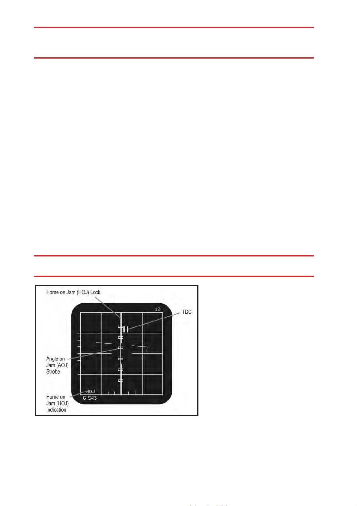
Sensors 73
hYou cannot fire AIM-7 missiles when using TWS mode. You must
designate the PDT or an SDT a second time and switch the radar to STT
mode.
Use TWS mode with caution. The radar cannot actually track multiple targets while
scanning a large volume of airspace. Instead, the radar scans each target, predicts
where the target will move to, searches a wider pattern, and then returns to scan
the predicted position of each target. As long as the target flies a relatively
consistent course, this system works fine; however, if the contact makes a
sudden, aggressive course change, the radar will continue to show the predicted
course until it completes enough of the scan cycle to realize it has lost contact
with the target. The target may move a considerable distance unseen while the
VSD continues to display the erroneous position.
TWS is a powerful mode and necessary in order to fire multiple AIM-120 missiles
at multiple targets. However, keep in mind its limitations and use it in conjunction
with RWS and TWS modes.
4.104 Home On Jam (HOJ) Mode
If the radar detects a jamming signal, it displays a series of hollow rectangles
along the bearing to the jammer on the VSD. If using AIM-7 or AIM-120 missiles,
you may select and designate one of the Angle Of Jam (AOJ) rectangles. A
vertical line appears through the AOJ markers and the VSD will display “HOJ”
along the upper edge. Any AIM-7 or AIM-120 missiles will fly down the bearing of
the jammer, attempting to locate the source.
hThe AOJ markers only indicate the bearing to the jammer. It does not
indicate the target’s speed, altitude, heading, or range.
As you close on the jammer,
eventually the reflections from
your radar will be more powerful
than the signals from the
enemy’s jammer. This is called
burn through and indicates your
radar is powerful enough to
overcome the jamming. Once
you reach burn-through range,
the contact will appear on the
VSD, replacing the AOJ marks.
HOJ display
4.105 Vertical Search (VS) Auto-Acquisition Mode
Vertical Search mode searches a fixed scan pattern 7.5° wide, ranging from 5°
below the aircraft to 55° above. Range is fixed at 10 nautical miles. It
automatically locks onto the target with the largest RCS within that pattern. After
locking a target, the radar switches to STT mode.
Page 96

74 Sensors
This mode is particularly useful during a close-range, turning
fight when you’re stuck in lag and can’t quite bring your
aircraft’s nose onto the target. This mode scans a pattern along
your lift vector, helping you acquire targets up to 55° offboresight.
The VSD shows no useful targeting information in this mode.
Refer to the Vertical Search HUD mode for additional information.
4.106 Boresight (BORE) Auto-Acquisition
Mode
BORE mode works nearly identically to VS mode, but utilizes a
smaller scan pattern aligned along the aircraft’s longitudinal
axis. The pattern is only 2° wide and 2 bars tall. As with VS
mode, the HUD displays the significant targeting information,
not the VSD. The radar locks the target with the greatest RCS
BORE Auto- Acquisition
Mode
within the BORE pattern and switches to STT mode.
VS Auto -Acquisition
Mode
4.107 Gun Auto-Acquisition Mode
Gun mode is used in close-range dogfights. Gun mode
engages the cannon and selects a fixed scan pattern, 60° wide
and 20° tall. The range is set to 10 nautical miles. As with VS
and BORE modes, the HUD shows the relevant information,
not the VSD. The radar locks the target within the pattern with
the greatest RCS and switches to STT mode.
Guns Auto-Acquisition
Mode
4.108 FLOOD Mode
FLOOD mode is a close-range, visual dogfight mode used in conjunction with
AIM-7 missiles. The radar emits energy in a continuous, 16° wide, 40° tall pattern.
The azimuth and elevation indicators appear, as described for RWS mode, but the
antenna position carets do not move. The range indicator is fixed at 10 nautical
miles. The word FLOOD appears above the VSD.
hIn FLOOD mode, all useful targeting information appears on the HUD,
not the VSD.
This mode does not display contacts, nor allow lock on. It “floods” the vicinity
with radar waves. Any AIM-7 missile launched in FLOOD mode will track the
target with the greatest RCS within the flood pattern. If the target moves outside
of the HUD’s reference circle for more than 2 seconds, the missile loses lock and
goes ballistic.
4.2. A-10A Maverick Seekers
The A-10A carries no radar or detection system other than the seeker heads in the
AGM-65 Maverick missiles. The A-10A carries two versions of the Maverick, the
television-guided AGM-65B and the Imaging Infrared (IIR) guided AGM-65K.
The AGM-65K and AGM-65D use the same procedure to attack a target. The first
Page 97

Sensors 75
step is to designate the point on the ground near which your desired target is
located. Press the TAB key to stabilize the Mavericks seeker on this point in pitch
and yaw. Once stabilized, you can move the center of the pointing cross above
your desired target. Once the target is in range, the seeker will automatically lock
on to the target and follow it. You can launch the missile at this time.
The only difference between the two versions of the Maverick is that the AGM65K is optically guided with no magnification level and the AGM-65D is infraredguided and has an optional 6X magnification level in addition to the default 3X.
The view from the seeker head appears on the TV monitor located on the right
side of the instrument panel. The monitor shows the view with either no
magnification or 4x zoom. The unmagnified view includes Narrow Field of View
brackets. The brackets show the field of view visible in the monitor when zoomed
to 4x magnification.
The pointing cross moves within the monitor,
indicating where the missile seeker is looking
relative to the aircraft centerline. For example, if the
pointing cross is above and to the right of the center
of the monitor, the missile is looking above and to
the right of the aircraft’s nose. The AGM-65 can
acquire 60° off boresight, but launch constraints
require the missile be within +/- 30° off boresight.
AGM-65B with Tracking Gate
Typical AGM-65B View
Page 98

76 Radar Warning Receivers
RADAR WARNING
RECEIVERS
Aircraft, ships, and ground stations broadcast radar signals everywhere searching
for adversaries. Naturally, modern combat aircraft carry receivers designed to
detect these emissions and warn pilots. Although Eastern and Western aircraft
designers take slightly different approaches to the common problem, all radar
warning receivers (RWRs) share some common aspects.
First, RWR equipment is passive, meaning it emits no signals of its own. It
“listens” for the emissions from other transmitters, indicating the type of
transmitter, the bearing to the transmitter, and if the emitter has locked onto the
aircraft. RWR gear, however, does not indicate the range to the emitter.
hRWR equipment does not indicate the range to the transmitter.
5.1 U.S. Aircraft
The A-10 and F-15 radar warning receivers look slightly
different, but operate virtually the same. In either
aircraft, the center of the RWR represents your aircraft.
The circular display represents the bearing around the
plane; the top of the display indicates bearing 0 (directly
ahead) while the bottom denotes bearing 180 (directly
behind). The position of icons around the circle,
therefore, indicates the bearing to the emitter.
F-15 Radar Warning Receiver
The screen presents icons in two
rings. The rings indicate the relative threat presented by the
radar sources, but do not indicate the range to the emitters.
The outer ring shows radars in search mode; the inner ring
displays radars that have locked onto your aircraft. A tone also
sounds, providing an audible alarm when radar locks onto
your aircraft. Icons representing incoming radar-guided
missiles will flash.
A-10 Radar Warning Receiver
In the A-10, search and launch warnings are also indicated on the warning panel.
Radar emitters are abundant on the modern battlefield. The RWR equipment can
quickly become confusing, distracting, and even overwhelming as it displays the
wide variety of contacts it detects. Consequently, the RWR supports three
“declutter” levels:
• Show All: Shows all detected radar sources.
• Show Only Lock: Shows only radars locked onto your aircraft.
• Show Only Launch: Shows only radar-guided missiles tracking your aircraft.
Page 99

Radar Warning Receivers 77
Each icon on the RWR display consists of two components: the radar category
and the emitter type. Radars come in five general categories:
• Early Warning Radars: The EW icon appears on the screen indicating
the bearing to the radar emitter. The scope displays EW regardless of the
emitter type (1L13 or 55G6 Russian EWR stations).
• Airborne Radars: All airborne radars carry the ^ character above the
emitter type, including AWACS and fighter radars.
• Ground-Based Radars: Icons for all ground-based radars, including SAM
and AAA sites, appear within a box.
• Ship-Based Radars: Radar emitters mounted on ships appear with a
bracket beneath the emitter type.
• Active Missiles: Icons for radar-guided missiles with onboard emitters
appear within a diamond.
Symbols coupled with the radar category indicate the platform carrying the radar
system. The following tables indicate symbols used for airborne, naval, land-based,
and missile guidance radars.
Airborne Radar Symbology
Aircraft RWR Icon
MiG-23ML 23
MiG-29 29
MiG-29K 29
MiG-31 31
Su-27 27
Su-30 30
Su-33 33
F-4E F4
F- 14 A 1 4
F- 15 C 1 5
Active Radar-Guided Missiles
Missile RWR Icon
R-33 (AA-9) 9
R-77 (AA-12) 12
AIM-54 54
AIM-120 AM
F- 16 C 1 6
F/A-18C 18
A-50 50
E-2C E2
E-3A E3
Page 100

78 Radar Warning Receivers
Ship-Based Radars
Ship Class Radar System RWR Icon
Azov (Kara) SA-6 6
Albatross (Grisha-5) SA-8 8
Grozny (Kynda) SA-3 3
Kuznetsov SA-15 15
Kuznetsov 2S6 S6
Vinson Sea Sparrow SS
Moscow (Slava) SA-10 10
Moscow (Slava) SA-8 8
Nanuchka SA-8 8
Neustrashimy SA-15 15
Neustrashimy 2S6 S6
Oliver H. Perry Standard Missile SM
Orel (Krivak-3) SA-8 8
Rezky (Krivak-2) SA-8 8
Skory (Kashin) SA-3 3
Spruance Sea Sparrow SS
Ticonderoga Standard Missile SM
Ground-Based Radars
Radar NATO Codename RWR Icon
S-300PS 40B6M tr SA-10 10
S-300PS 40B6MD sr SA-10 Clam Shell CS
S-300PS 5H63C tr SA-10 10
S-300PS 64H6E sr SA-10 Big Bird BB
S-300V 9532 tr SA-12 12
S-300V 9S15MT sr SA-12 Bill Board BD
S-300V 9A82 in SA-12 12
S-300V 9A83in SA-12 12
Buk 9S18M1 sr SA-11 Snow Drift SD
Buk 9A310M1 in SA-11 11
Kub 1S91 SA-6 6
Osa 9A22 SA-8 8
Strela-10 9A33 SA-13 13
Dog Ear Radar Dog Ear DE
Tor 9A331 SA-15 15
Tunguska 2S6 S6
Shilka ZSU-23-4 ZSU-34-4 23
Roland ADS Roland RO
Roland Radar Giraffe GR
Patriot str Patriot P
Gepard Gepard GP
Hawk sr I-HAWK PAR HA
Hawk tr I-HAWK HPI HA
Vulcan M-163 VU
Zu-23 Zu-23 AA
 Loading...