

Page 1

™
LINKS 2001
PLAYER’S MANUAL
Page 2

Indeo Video Interactive Copyright © 1998 Intel Corp. Indeo is a registered trademark of Intel Corporation. TrueMotion
Playback Engine and compression Software Copyright ©The Duck Corp.1993-1998 TrueMotion is a registered trademark
of The Duck Corp.
Special Thanks to:
The USGA (United States Golf Association)
David Joy as “Old Tom Morris”
St. Andrew’s Links Trust
Information in this document is subject to change without notice. The names of companies, products, people, characters, and/or data mentioned herein are ctitious unless otherwise noted. Complying with all applicable copyright laws
is the responsibility of the user. No part of this document may be reproduced or transmitted in any form or by any
means, electronic or mechanical, for any purpose, without the express written permission of Microsoft Corporation. If,
however, your only means of access is electronic, permission to print one copy is hereby granted.
Microsoft may have patents, patent applications, trademarks, copyrights, or other intellectual property rights covering
subject matter in this document. Except as expressly provided in any written license agreement from Microsoft, the
furnishing of this document does not give you any license to these patents, trademarks, copyrights, or other intellectual property. © & (p) 2000 Microsoft Corporation. All rights reserved.
Microsoft, DirectPlay, DirectX, Links, MS-DOS, PowerStroke, Windows, and Windows NT are either registered trademarks
or trademarks of Microsoft Corporation in the United States and/or other countries.
Other product and company names mentioned herein may be the trademarks of their respective owners.
TECHNICAL SUPPORT
Support Online: To easily diagnose and answer technical questions yourself, visit http://support.microsoft.com/
support. Or you can browse support information about your product conveniently consolidated at http://
support.microsoft.com/support/games.
Standard No-Charge Support: Monday-Friday, excluding holidays, Microsoft offers unlimited no-charge support for
Links LS 2000. In the United States, call (877) 632-2080, 6:00 A.M. to 6:00 P.M. Pacic Time, Monday-Friday and 9:
00 A.M to 3:00 P.M Pacic Time, Saturday-Sunday. In Canada, call (425) 635-7178, 6:00 A.M. to 6:00 P.M. Pacic Time.
Toll-charges may apply.
Pay-Per-Incident Support: In the United States, for $15US per incident, call (800) 936-5600, 24 hours a day, seven
days a week. In Canada, for $45CDN plus tax per incident, call (800) 668-7975, 8:00 A.M. to 8:00 P.M. Eastern Time,
Monday-Friday, excluding holidays. Fees are billed to your VISA, MasterCard, or American Express card.
Text Telephone: Available Monday-Friday, excluding holidays. In the United States and Canada, (425) 635-4948, 6:
00 A.M. - 6:00 P.M. Pacic Time. In Canada, (905) 568-9641, 8:00 A.M. - 8:00 P.M. Eastern Time.
Additional Support Information: See the Product Support topic in Help for more information or support
outside the United States or Canada. Support services and prices listed here are available in the United States and
Canada only and are subject to Microsoft’s then-current prices, terms, and conditions, which are subject to change
without notice.
CREDITS
Links 2001 /Arnold Palmer Course Designer Edition
Copyright © 1990-2001 Microsoft Corporation.
Links is a registered trademark of Microsoft Corporation.
All Rights Reserved.
PRODUCT UNIT MANAGER
Dave Curtin
CHIEF GAME DESIGNER
Bruce Carver
PROGRAM MANAGERS
John Berven Ross Curtin
PRODUCT PLANNING
Mark Van Langeveld
Nielsen
Zeke McCabe
PRODUCT MANAGERS
Darren Steele Scott Lee
DEVELOPMENT LEADS
Matt Dawson—
Paul Johnston— Arnold Palmer
Course Designer
ART LEAD
Eric Parkinson
TEST LEADS
Michael Burge—
Russell Jenkins—Arnold Palmer
Course Designer
COURSE DEVELOPMENT MANAGER
Mark McArthur
MULTIMEDIA LEAD
Bill Biggs
AUDIO LEAD
Jon Clark
SOFTWARE DEVELOPMENT
Links 2001 Course Designer
Matt Dawson
Rich Moore
Mark Snow
Sandeep Kharkar
Mark Hulka
Russell Hunter
Phillip Knight
Russell Almond
Hao Chen
Jeff Harward
Jeremy Carver
Lanny
Links 2001
Links 2001
Paul Johnston
Parham Mohadjer
Chris Carver
George Manousakis
J.J. Hoesing
Brian Stringham
ART
Eric Parkinson Allen Brockbank
Brandon Wright
Corey Day
Matt Dazley
COURSE BUILDERS
Jeremy Carver
Mark Mazzei Brett Petric
Thorsten Moeckel
Nate Whitmer
John Harmon
COURSE ACQUISITION
Steve Barnes
Mike Yurth
Scott Wright
Brady Donley
AUDIO LEAD/STUDIO LIGHTING
Jon Clark
GOLFER DIALOGUE WRITER
Aaron Conners
MUSIC
Matt Heider of Next Level Music
MULTIMEDIA MANAGER
Bill Biggs
MULTIMEDIA CONTENT
Steve Barnes
Dave Brown
Gerry Graves
INTRO VIDEO
Bryan Nielsen of Digital VooDoo
QUALITY ASSURANCE
Seth Behunin
Michael Burge
Bruce Darby
Kevin Homer
Russell Jenkins
Lon Oswald
Kelly Peterson
Brian Johnson
Nathan Larsen
Mike Yurth
Alan Johnson
Rich Rounds
Rick Krause
Scott Wright
Lanny Nielsen
Zeke McCabe
Les Oswald
Bill Biggs
Les Oswald
Dave Shelton
Bill Biggs
Josh Moore
Chris Okelberry
Nick Perkins
Michael Russell
Ron Jenkins
Tyler Pendleton
GRAPHICS SPECIALISTS
Brad Beck Tony Carver
Nick Carver
Paul Johnson
Scott Draper
Dave Langborg
Pat Carver
BOX DESIGN
Jim Fedor
signs
GOLFERS
Arnold Palmer
Sergio Garcia
Annika Sörenstam
Nakia Davis Brad Beck
Brett Glaser
Chris Lin Lynn Landgren
Julie McMillen
DOCUMENTATION
Steve Barnes
Aaron Conners
ONLINE HELP
Sandi Beckstead
Nancy Martinson
PRINT PRODUCTION
Andrea Heuston
LOCALIZATION
Lawrence Krzemien-Smith
Victoria Olson
Kaoru Ito
Yuko Yoshida
Kazuyuki Kumai
Yasmine Nelson
Hiroshi Ogura
Jason Shirley
Jonathon Young
VOICE TALENT
Craig Bolerjack
Kevin Jones
ANGELIC CATERING
Angela Strong
Marie-France Hansen
Ryan Fedor
Clark Spencer
Ben Kohler
Jake Johnson
Dave Geurts
Ayzenburg De-
Larry Austin
Shirley Baer
Ron Boone
Chris Jones
Kami Whitehead
Sandi Beckstead
Nancy Martinson
Steve Barnes
Tyler Pendleton
Takayoshi Asahina
Peter Fitzpatrick
Steve Belton
Suzanne Boylan
Fionn Stakelum
Kazuyuki Shibuya
Yutaka Hasegawa
Alema Harrington
Jill Manfull
1200 Part No. X05-96990
Page 3

Page 4

Links 2001
Table of Contents
Getting Started ................................................................9
Installing Links 2001™ .................................................... 9
Starting Links................................................................. 9
Help ..........................................................................10
Lessons......................................................................10
Other Main Screen Options...........................................10
Welcome to Links 2001! ................................................. 11
The Arnold Palmer Course Designer...................................11
Links 2001 Courses.........................................................11
Other New Features ........................................................12
Playing Links 2001........................................................ 13
Quick Start....................................................................13
On the Tee ....................................................................13
The Links Main Cam ....................................................13
Selecting a club ..........................................................14
Aiming ......................................................................15
Swinging....................................................................15
Post-shot options ........................................................17
Using the Links In-game Pop-up Menus............................. 18
Rotate ..........................................................................18
Shot Options .................................................................18
Display .........................................................................19
Clubs ............................................................................20
In-Game Menu ...............................................................21
Customizing the Gameplay.............................................. 22
The Play Golf Screen.......................................................22
Practice ........................................................................22
New Round....................................................................23
Modes of Play .............................................................24
Mulligans and Gimmes .................................................25
Players..........................................................................26
Designating Players.....................................................26
Selecting Teams ..........................................................26
Creating and Editing Players.........................................27
Using the PowerStroke Swing .......................................... 29
7
Page 5
8
9
Hitting the Ball .............................................................29
Draw/Hook and Fade/Slice ...........................................31
Push and Pull .............................................................31
The PowerStroke Swing ...................................................32
The Full Swing............................................................32
Chipping and Putting ..................................................34
Sand Shots.................................................................36
Adjusting PowerStroke Sensitivity....................................37
Online Play....................................................................38
MSN Gaming Zone ..........................................................38
Chapter 1
Getting Started
Installing Links 2001™
To install Links under Microsoft® Windows® 95, Windows 98,
Windows NT or Windows 2000
1. If you have the Auto-install feature, insert the CD in your
CD-ROM drive and follow the instructions on the screen.
-or-
1. Insert the Links CD 1 in your CD-ROM drive.
2. Click Start.
3. Click Run.
4. Type: D:\SETUP, and then press ENTER.
Note D: designates the drive letter of your CD-ROM drive.
5. Click OK.
6. The setup window appears and will guide you through the
installation process.
Starting Links
During installation, Links creates its own Program group on your
Start menu.
chapter
1
To start Links
1. Click Start (or go to Step 4 if you made a desktop shortcut
during installation).
2. Point to Programs.
3. Point to Microsoft Games.
4. Point to Links 2001.
5. Double-click the Links icon.
Page 6

10
11
The rst screen to appear
is the Links Main Screen.
Two useful options can be
accessed from this screen:
Chapter 2
Welcome to Links 2001!
chapter
Help
This manual covers the
“basics” of installing,
loading and playing
Links. For more in-depth
information, you are
referred to Links Help.
When you click a Help
button or press F1, the
Help screen appears. Use
the Help Index with its comprehensive list of topics by either typing in a topic or scrolling through the Index.
Lessons
If you are new to Links, we highly recommend viewing the Links
Lessons to learn how to play the game. Advanced players may also
discover ways to improve their skills with these lessons, which
include Swing Type, Menu and Aiming, Golf Tools, Shot Types,
Players in the Game and MSN Zone.
Other Main Screen Options
Quick Start—The fastest, easiest way to start playing Links.
See chapter 3—“Playing Links 2001.”
Play Golf—Click this to customize options before playing Links.
See chapter 5—“Customizing the Gameplay.”
Players—Create or edit new or existing golfers. See pages 27-28.
Videos—View video presentations about the Links 2001 courses.
Online Play—Go to MSN Gaming Zone, join the Links Tour or con-
nect directly with friends via LANs or the Internet. See chapter
7—“Online Play.”
Options—Customize sound, graphics, and play options.
Exit—Click to return to Windows.
If this is your rst time playing Links, you are about to enjoy
the nest golf game in the world. If you are an experienced
“Linkster,” here is what we’ve added to make the best even better:
The Arnold Palmer Course Designer
Now you can create your own courses in exquisite Links-quality detail using a modied version of the actual Links rendering
engine.
Refer to chapters 8-14 for detailed information.
Links 2001 Courses
St. Andrews Links, Old Course (Scotland)—The birthplace of
golf, as well as the site of the Millennium Open—the inaugural
British Open of the 21st century.
Aviara (Carlsbad, California)—An Arnold Palmer design with
unparalleled terrain, water, and rockwork.
Westelds (Virginia)—An instant classic, carved out of 300
acres of oak forest and featuring a colonial-style clubhouse and a
Civil War burial mound off the 13th fairway.
Chateau Whistler (Canada)—Originating on the foothills of the
Canadian Rockies, this majestic course climbs toward the summit
and then plunges down to the homeward holes, providing some of
the most breathtaking vistas imaginable.
Princeville (Kauai, Hawaii)—This course, repeatedly crowned
“Number One in Hawaii,” winds through lush tropical mountains
and valleys.
Mesa Roja (Fantasy Course)—Designed by the talented Links
team and featuring PGA golf professional Lanny Nielsen, this
course was inspired by the unique red rock and desert scenery of
the southwestern U.S.
2
Page 7
12
13
Other New Features
14 New Golfers—Play with Arnold Palmer, Sergio Garcia, Annika
Sorenstam, or any of eleven other awlessly rendered golfers and
enjoy each one’s unique comments and personality.
User-Friendly Additions—A new Quick Start option gets you on
the tee with only a few clicks; interactive lessons instruct you on
how to play and customize Links 2001; an “AID System” reacts to
recurring gameplay mistakes with helpful suggestions.
Online Improvements—MSN Gaming Zone integrates fully with
Links 2001, making multiplayer games more accessible; improved
connectivity offers better input and feedback from all online
players; Ready Golf play option speeds up Internet play while still
allowing all players to see each other’s shots.
Chapter 3
Playing Links 2001
If you want to customize the gameplay settings before playing,
or if you want to go to Practice, refer to Chapter 5—“Customizing
the Gameplay.” If you want to play as soon as possible, a Quick
Start option is available.
Quick Start
If you choose to “Quick Start,” all you need to select is a course
to play and the player(s).
To Quick Start
1. Click Quick Start on the Links Main Screen.
2. From the Quick Start screen, select a course in the Course
To Play pull-down.
3. Click Single Player, Two Players, Three Players, or
Four Players
4. Select which players you want from the Players in the
Game pull-down(s).
5. Click Begin Play.
.
chapter
3
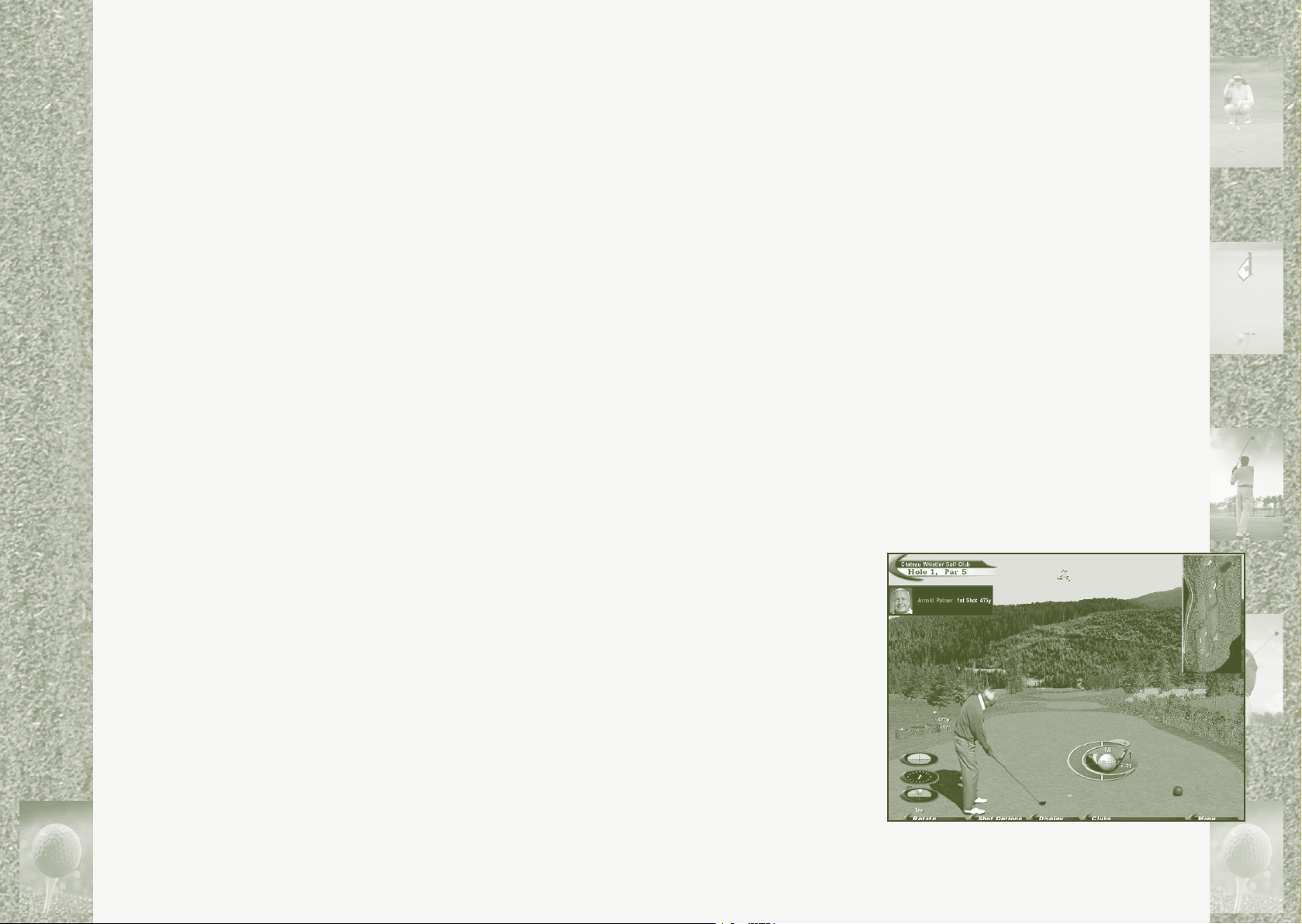
On the Tee
You’re ready to play!
When the course nishes
loading, a “Hole Preview
Cam,” showing the layout
of the rst hole, is superimposed over the Links
“Main Cam.”
• Click OK to
close the Hole Pre
view Cam.
The Links Main Cam
The Links “Main Cam” is
the primary game screen.
Once the Hole Preview
Cam is closed, the Main
Cam is unobstructed except for seven small information displays:
-
Page 8
14
15
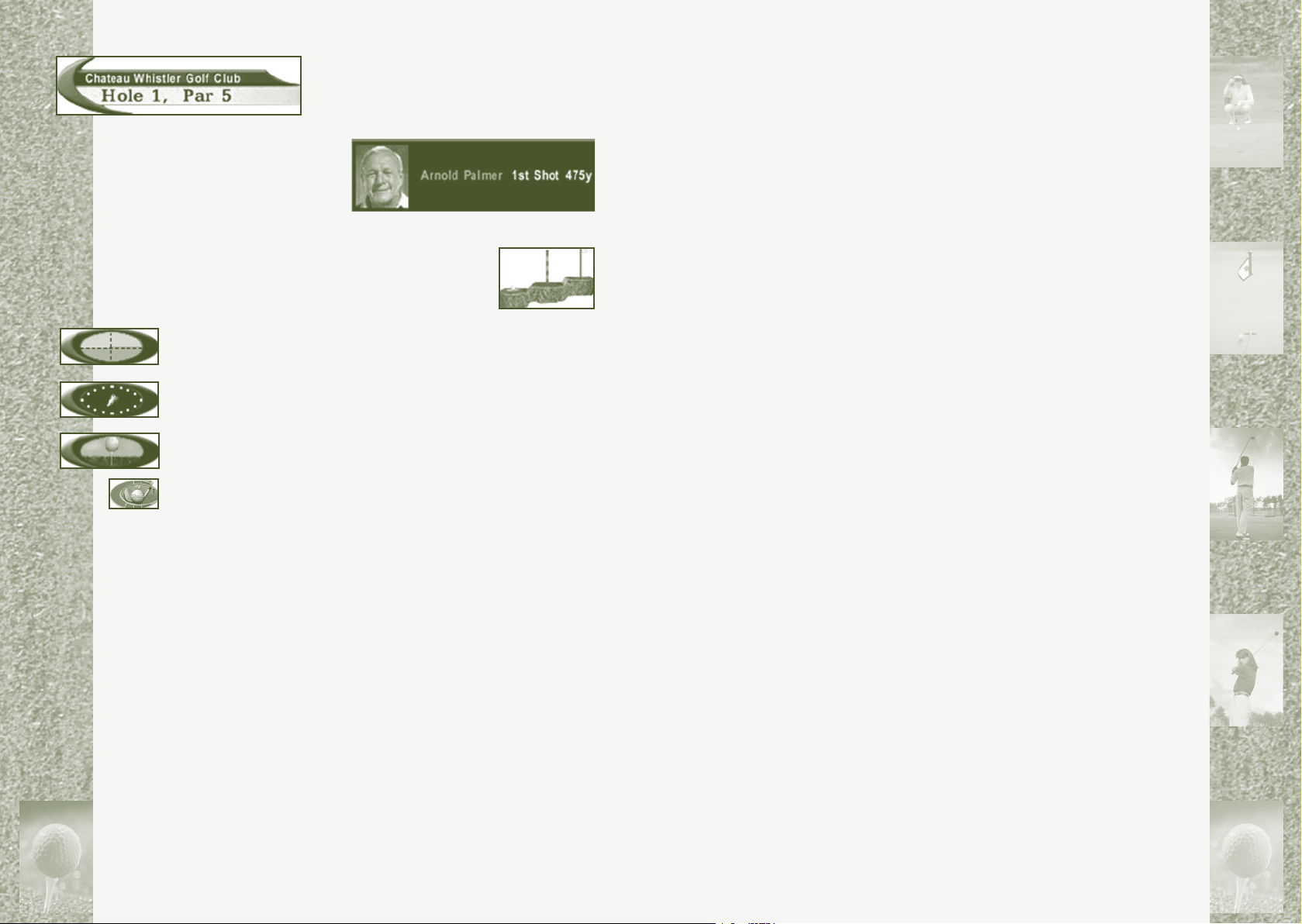
Course Information—Displays the course,
hole number and par for the hole.
3. When you decide on a club, click it to select it.
Note: Move the pointer over any club on the Clubs menu to
display the club’s average distance.
Player Information Displays the player next to
hit, the number shot the
player is about to hit, and
the player’s score as of the
last completed hole.
Elevation Information—Displays the relative differences in elevation between the ball, the Aiming
Marker (see below), and the pin.
Slope Indicator—Displays the angle of the terrain on which
the ball lies.
Wind Indicator—Displays the direction and strength of the wind
(if applicable).
Lie Indicator—Displays the type of terrain on which the ball lies.
Swing Gauge—Displays the club currently selected.
Note: The display in the upper-right corner is the “Top Cam”; the
In-game Menu tab is in the lower-right corner. For information on
these features, as well as the pop-up menus located at the bottom
of the Main Cam, refer to the Help Index (“Top Cam”, “In-game
Menu”, “Pop-up Menus”) or see chapter 4—“Using the Links Ingame Pop-up Menus”.
All you need to do now is select a club, aim your shot and swing.
The following are basic instructions; For more detailed information on any topic, refer to that topic in the Help Index.
Selecting a club
A club is automatically selected for you, but you are free to
change it.
Aiming
When you are ready to tee off, the Aiming Marker (a red
and white striped pole) appears. For maximum accuracy, you must
position the Aiming Marker in the direction you want to hit the
ball.
To aim your shot
1. Hold down the left mouse button to display the Aiming
Marker. This can be done in either the Main Cam or the Top
Cam.
2. Move the Aiming Marker to the direction you want the
ball to go.
Note: Unless you are using the “Easy Swing” (refer to
the Help Index (Topic: “Easy Swing Lesson”), the Aiming
Marker has no effect on the distance of your shot, only
the direction.
3. When the Aiming Marker is in position, release the left
mouse button. To make the Aiming Marker appear or disappear, click the right mouse button.
Note: The Aiming Marker turns yellow when placed in an
invalid position. Also, when used on the green in the Main
Cam, a white arrow—called the Breakline Indicator—appears at the base of the Aiming Marker. This indicates the
steepest slope of the terrain in relation to the Aiming Marker
and is especially useful when putting. The breakline can be
displayed off the green as well by holding down the SHIFT
key while aiming.
Swinging
Links offers three swing types: Classic, Easy Swing, and Power
Stroke™ (see chapter 6—“Using the PowerStroke Swing”). The
rst time you use Quick Start, the Classic swing type is automatically selected.
-
To select a club
1. Move the pointer to the bottom of the screen to reveal the
pop-up menu tabs.
2. Click Clubs.
For instructions on changing swing types during a round, see page
18, “Shot Options.”
Page 9
16
17
To use the Classic swing (two- or
three-click)
1. Position the cursor over the
swing gauge in the bottom center
of the Main Cam.
2. Click and hold down the left
mouse button to start the swing.
-or-
3. Click the left mouse button.
4. A yellow indicator band moves
around the swing gauge. When it
reaches the green line at the 12
o’clock position, release the left mouse button (or, click
it again—see Step 2). A red line, called the power mark,
marks the release point.
Note: If the power mark is left of 12 o’clock (early), your
swing has less power, but more control. If it is right of 12
o’clock (late), your swing has more power and less control.
5. The indicator band continues to the end of the swing
gauge, reverses direction and is now red as it moves back
around. When it reaches the green line at the 6 o’clock
position, click the left mouse button again. A yellow line,
called the snap point, appears.
Note: The snap point determines the direction of your shot:
Left of 6 o’clock, the ball goes left and hooks, right of 6
o’clock, the ball goes right and slices—the more off-center,
the greater the effect.
Notes
• The swing gauge changes when you’re chipping or putting,
providing shorter, more controlled swings, and the snap point
is more forgiving than when you’re taking a full swing.
• Unlike other clubs, the putter has no average distance, so the
distance a putt rolls is determined by where the power mark
is set and the contours of the green.
• For more information on chipping and putting, see “Swing
Type Lesson” or refer to the Help Index (Topic: “Chipping/
Putting Swing”).
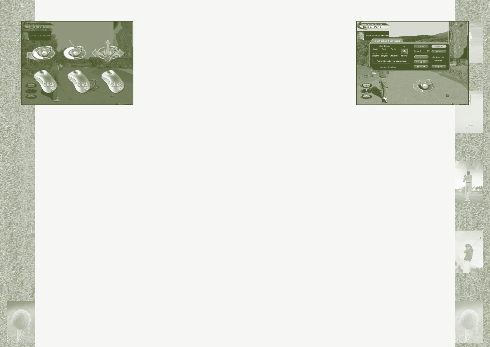
Post Shot Options
After each shot, the Post Shot
Selection dialog appears, providing
information about the shot, options in case of penalties, and
selections for your next shot. The
three graphical indicators on the
left show (1) the distance the shot
traveled before landing (in air), (2)
total distance, and (3) the distance
left to the hole (to pin). The terrain on which the ball is currently
lying is also displayed. Additionally, there are several buttons in the Post Shot Selection dialog.
Replay—View an instant replay of the last shot, either from
where it was hit (forward) or where it landed (reverse).
Rehit—Re-hit the last shot. This adds an extra stroke to your
score. If “gimmes” are allowed, the Rehit button is replaced with
the Gimme button (see below) in certain situations.
Gimme—Take a “gimme.”
Note: Refer to “Mulligans and Gimmes,” page 25, for
more information.
Pick Up Ball—Quit the current hole and advance to the next.
Your score for the hole will be a 12.
Save Shot—Save the instant replay of the last shot so it can be
viewed later.
Drop—Drop the ball at a different location. This is necessary if
your shot lands in a hazard or on an unplayable lie.
Refer to “Drop Lesson” in the Help Index for more information and
instructions on how to drop.
Mulligan—Take a “mulligan.”
Note: Refer to “Mulligans and Gimmes,” page 25, for
more information.
Page 10
18
19
Chapter 4
Using the Links In-game
Pop-up Menus
There are ve pop-up menu tabs (“Rotate”, “Shot Options”, “Display”, “Clubs” and “Menu”) located along the bottom of the Links
Main Cam. Of these, only “Menu” (in-game menu) is visible at all
times. To reveal the other four, move the pointer to the bottom of
the screen.
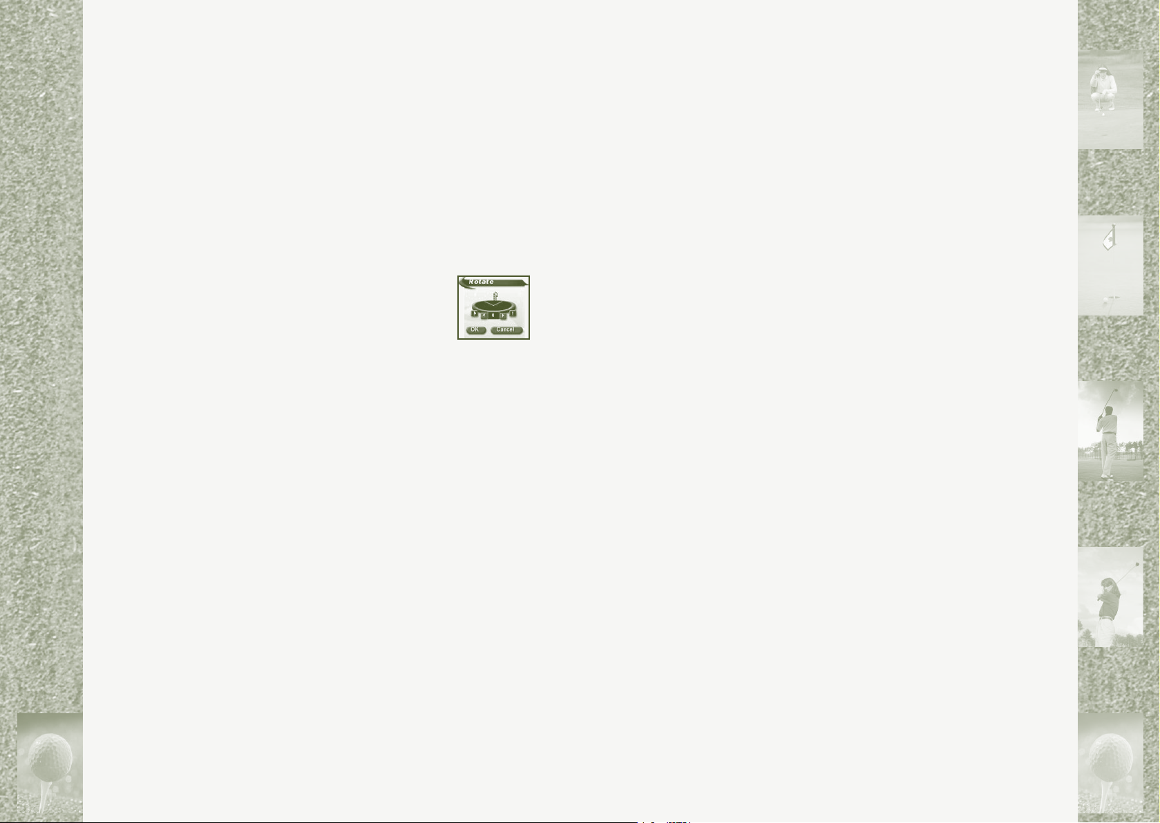
Rotate
Before each shot, the golfer is positioned to face
the center of the fairway or the green. Occasionally,
you may want or need to rotate the golfer so that
he/she faces a different direction.
To rotate the golfer
1. Move the pointer to the bottom of the Main Cam and click
Rotate.
2. Click the ag icon to reposition the golfer to face the
agstick on the green. Click the Aiming Marker icon to
reposition the golfer toward wherever you’ve set the Aiming
Marker. Click the right or left arrow to rotate the golfer in
that direction.
3. When you’re nished, click OK. The Main Cam will redraw
in the new direction.
Shot Options
Five shot options are available in this menu: Swing Options,
Gimme, Skip to Player, Address, and Drop.
To select a Shot Option
1. Move the pointer to the bottom of the Main Cam and click
Shot Options.
2. Click the option you want.
Note: The Gimme option is disabled if you chose not to allow
gimmes before starting the round. “Address” will toggle the
golfer away from, and back to, the ball (see below).
Swing Options (ALT+W)—Select one of three swing types: Classic, Easy, or PowerStroke.
For more information on swing types, view the “Swing Type Lesson” or refer to the Help Index (Topic: “Swinging”). Also, refer to
Chapter 6—“Using the PowerStroke Swing.”
Gimme (ALT+E)—Take a “gimme” if your ball is within a pre-determined distance of the pin.
Refer to “Mulligans and Gimmes,” page 25, for more information.
Skip to Player (ALT+K)—Allow players to hit out of order.
Note: All players must be off the tee before any player(s) can go
one shot ahead.
Address (ALT+A)—Move the golfer away from (or back to) the
ball to allow a practice swing.
Drop (ALT+R)—Drop the ball at any time during a round.
Refer to the Help Index (Topic: “Drop Lesson”) for instructions on
how and when to drop.
Display
A wide selection of secondary windows that provide useful graphical and statistical information can be displayed over
the Main Cam and are available from the Display Menu
(descriptions below).
To open the Display menu
1. Move the pointer to the bottom of the Main Cam and
click Display.
2. Click the option you want.
Note: Selecting secondary windows make them appear on the
Main Cam. Click Tracer and Grid (see below) to turn (toggle)
them on and off.
Cameras (ALT+C)—Select from multiple cameras, including
Golfer Cam, Landing Cam, Main Cam, Pin Cam, Prole Cam, Side
Cam, Smart Cam, and Top Cam, which offer different views of the
golf course and your shots.
Note: Up to eight secondary camera windows can be superimposed
over the Main Cam at one time. These can be resized, moved, and
closed like a standard Microsoft window. Refer to the Help Index
(Topic: “Cameras”) for detailed information on
in-game cameras.
chapter
4
Page 11

20
21
Info Views—Displays a chat window (available when playing
on-line) or a camera (window) with information about the previous shot.
Spot Pin (ALT+P)—The agstick zooms toward, then away from,
the golfer in a direct line with the green.
Tracer (ALT+T)—Leaves a visible line showing the ight path
of a ball.
Grid (ALT+G)—Superimposes a grid over the terrain to make contours easier to read. This feature is especially useful
when putting.
Note: Unless modied, the Grid defaults to ON when golfers are on
the green.
Score Card (ALT+SPACEBAR)—Displays players’ scores for the current round.
Hole Preview (ALT+B)—Displays the top view of the hole currently being played.
Player Stats—Displays golfers’ individual playing statistics.
Game Stats—Displays the statistics compiled during the
current round.
Clubs
The Clubs menu displays all available clubs in
your “golf bag,” allows you to change your swing
setup (“Setup”), and offers all available shot types
(Straight, Draw, Fade, Punch, Flop, and Chip).
Notes
• The club selection on the Clubs menu can be customized.
Refer to the Help Index (Topic: “Players Screen”) for details.
For instructions on selecting a club, refer to page 14.
• View the “Shot Type Lesson” or the “Advanced Shot Setup
Lesson” for in-depth explanations of techniques and available options.
Menu
• Click Menu in the lower-right corner of the Main Cam to
view miscellaneous options:
Add Player—Add a new player to the group playing the
current round.
Remove Player—Remove a player from the group playing the
current round.
Preferences—Customize the gameplay with Sound Options, Game
Settings, Graphic Settings and Multiplayer Settings
(if applicable).
For more information, see Chapter 5—“Customizing the Game
play,” or refer to the respective topics in the Help Index.
Help—Go to the Links Help screen.
Save Game—Save your game so you can resume it later.
End Round—Exit the current round without exiting the
Links program.
Exit Links—Exit to Windows.
-
To open the Clubs menu
• Move the pointer to the bottom of the Main Cam and
click Clubs.
Page 12
22
23
Chapter 5
Customizing the Gameplay
Quick Start (see page 13), is a fast and easy way to get on the
tee, but in order to customize a round of golf to your personal
preference—and to see what Links 2001 really has to offer—click
Play Golf from the Links Main Screen.
The Play Golf Screen
There are ve options available to you on the Play Golf screen:
Resume—Continue a previously-saved round.
Refer to the Help Index (Topics: “Resume a Saved Game” and “Resume a Tournament”) for additional details.
Saved Shot—View a previously-saved instant replay.
Refer to the Help Index (Topic: “Viewing Saved Shots”) for additional details.
Virtual Tournament—Compete just like the pros on the Tour in a
four-round tournament against virtual opponents.
Refer to the Help Index (Topic: “Virtual Tournament”) for additional details.
Practice
Go to Practice mode, where you can work on technique, see how
a particular course plays, or experiment with various gameplay
options without playing an actual scored round.
Refer to the Help Index (Topic: “Practice Options”) for
additional details.
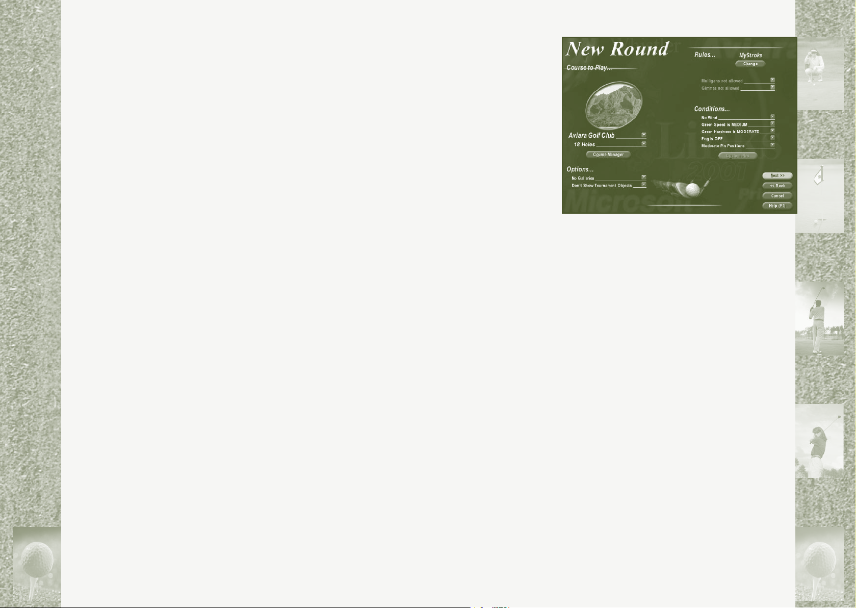
New Round
Start a customized round of golf.
Clicking this button
takes you to the New
Round screen, where
you begin by choosing a course and the
number of holes to
play.
To choose a course
and how many
holes to play
1. Under Course
to Play, click the drop-down button immediately under the
course “snapshot” window. The list of currently available
courses is displayed.
2. Click the course you want to play.
3. Click the button directly below the course selection dropdown to choose to play 18 holes, Front 9 or Back 9 on the
selected course.
Note: From the New Round screen, you can also access the Course
Manager dialog, which allows you to add or delete courses, check
the le size of your courses, change the directory in which course
les are stored, and verify which players are to be recorded for the
following round. Refer to the Help Index (Topic: “Course Manager”).
Once the course and number of holes have been dened, move
down to select the environmental options, and then over to customize the course conditions:
chapter
5
To select environmental options
1. Under Options, click the drop-down button(s).
2. Click your preferred Galleries and Tournament
Objects options.
Page 13
24
25
To customize course conditions
1. Under Conditions, click the drop-down button(s) next to
each of the four course elements to display the possible
conditions.
2. Click your preferred settings for the course conditions:
Wind conditions—affects the distance and arc of the ball in
ight. Choose No Wind, Breezy, or Windy.
Green Speed—determines the rolling speed of the ball on the
green. Choose Slow, Medium, or Fast.
Green Hardness—determines how the ball bounces when it
lands. Choose Soft, Moderate, or Firm.
Pin Positions—places the holes on the greens in different positions. Choose Easy, Moderate, or Difcult.
Notes
• Refer to the Help Index (Topic: “Course Settings”) for more
details on course conditions.
• The Custom Pin Position option allows you to create your
own pin placements on each green rather than using predened pin specications (Easy, Moderate, or Difcult).
For instructions, refer to the Help Index (Topic: “Custom
Pin Placement”).
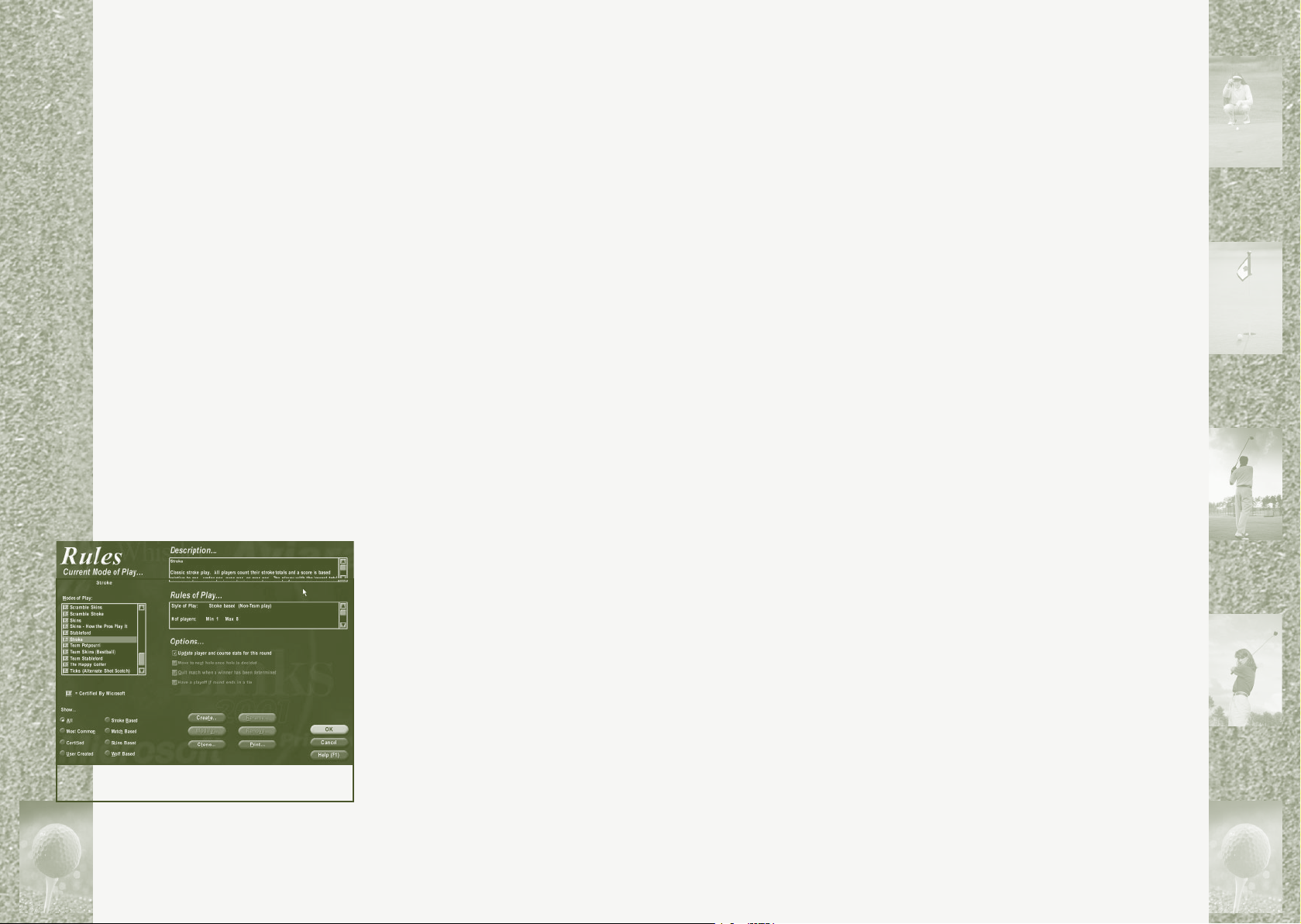
Modes of Play
The course is ready to go. Now you
need to choose a Mode of Play (i.e.
Stroke Play, Match Play, Skins, Best
Ball, etc.) and specify rules of play.
To choose a Mode of Play (MOP)
1. Under “Rules”, click the
Change button.
2. From the Rules screen, click the
Current Mode of Play drop-down
button.
3. Select an MOP from the list.
Notes
• A description of whichever
MOP is highlighted appears in the Descriptiondialog.
Rules of play for that MOP are displayed in the Rules
of Play dialog.
• The MOP Game Designer allows you to create, modify, add,
delete, and clone games. You can even exchange user-created games with friends. For more information on any aspect
of Modes of Play, refer to the Help Index (Topic: “Modes of
Play”).
4. Under Options…, select game-rule options for the upcoming round.
5. When you’re nished, click OK to return to the New
Round screen.
Note: If you select a Mode of Play that allows mulligans
and/or gimmes, you need to determine if you will allow
them and, if so, how many and when.
Mulligans and Gimmes
A “mulligan” is a re-hit taken without penalty and, while
not ofcially sanctioned, is sometimes allowed in friendly
play. Mulligans don’t affect your score, but are recorded on
your scorecard.
A “gimme,” like a mulligan, is often used in friendly play when
one player concedes a short putt to another player. If the ball
is on the green within a specied distance of the cup, you can
nish the hole without “putting out” and add one stroke to your
score. This practice is not ofcially sanctioned in Stroke Play, but
is allowed in match play (refer to the Help Index (Topic: “Mode of
Play”).
To allow or disallow Mulligans and Gimmes
1. From the New Round screen, under Rules, click the Change
button.
2. If you allow mulligans, specify how many: 1, 2, 5, 10 or
Unlimited. If you allow gimmes, specify how close the ball
must be to the hole: 6 inches, 1 foot, 2 feet, or 4 feet.
Notes
• Press CTRL+Z while the ball is in midair to take an
In-ight mulligan.
• If a mulligan or gimme is taken during a round, the score
will not “verify” as valid. Refer to the Help Index (Topic:
“Verify Score”) for information on verifying a player’s score.
Page 14

26
27
Players
Now that you’ve made your selections from the New Round screen
and clicked Next, it’s on to the Players in the Game screen, where
you designate which player(s) to include in
the round.
Designating Players
The Mode of Play you select dictates how many players can participate in the round, but the process of adding a player to the
game is always the same:
To select teams
1. Point, click, and hold down the left mouse button over
a player.
2. Drag and drop the player under a team number.
Note: If you’re undecided about which team a particular
player should be on, drop that player temporarily into the
Transfer section.
3. Repeat steps 1 and 2 until your teams are set.
4. Click Begin Play to start your new round.
To add a player to the game
1. Click the Add Player button.
2. From the Add Player dialog, click a player, and then click
OK. The name of the player is now displayed under “Player
Name” on the Players in the Game screen.
Note: To “record” the new player’s round and/or assign a
“caddy” to the player (so a recommended club will always
be chosen on each shot), click the respective boxes. Refer to
the Help Index (Topics: “Recorded Players” and “Recording a
Game”) for more information on the recording option.
3. Repeat steps 1 and 2 until all participating players are
added to the Player Name list.
4. If you selected a “team” Mode of Play, click Next to advance to the Select Teams screen. If you selected a “nonteam” Mode of Play, click Begin Play to start your round.
To remove a player from the Player Name list
• From the Players in the Game screen, click Remove, next to
the player’s name.
Note: You can add or remove a player form a game during
play through the Menu pop-up.
Selecting Teams
If you selected a team-based Mode of Play, you must divide your
players into teams before starting the round.
Creating and Editing Players
Links 2001 comes with 14 golfers, each with his/her own settings,
but you are free to create or edit players to suit your style.
To create a new player
1. From the Players In the Game screen, click Add Player, and
then click Create New Player.
-or-
1. From the Links Main Screen, click Players, and then click
Create Players.
2. Type a name in the “Create Player” dialog.
3. Choose if the player will be a “computer opponent” or not,
and then click OK.
4. On the Player screen, four tabbed pages (“Settings”, “Appearance”, “Clubs”, “Club Distances”) are displayed. Click
Settings, and then specify the new player’s swing type,
skill level, tee position, and grid settings.
5. Click Appearance and then the drop-down arrow under
“Golfer Animation” to choose a golfer. Specify if the golfer
should play right- or left-handed.
Note: Refer to the Help Index (Topic: “Adding a Golfer Ani-
mation”) for more information.
6. Click Clubs and select a maximum of 13 clubs (not including the putter) for the player.
7. Click Club Distances and set the distances the player’s
clubs will hit the ball.
8. Click Tour Player to make the player a “tournament”
player.
Note: Refer to the Help Index (Topic: “Tournament Set-
tings”) for more information.
9. When you nish creating your new player, click OK.
Page 15

28
29
To edit a player
1. From the Links Main Screen, click Players.
2. From the Players in the Game screen, click Add Player.
3. Highlight a player and click Edit Player.
4. On the Player screen, click any of the four tabbed pages
(Settings, Appearance, Clubs, Club Distances) and edit the
player’s settings.
5. When you nish editing the player, click OK to save
the changes.
Note: This process can also be used to check a player’s char-
acteristics, provided you exit without making edits.
Chapter 6
Using the
chapter
PowerStroke Swing
6
The PowerStroke Swing is unique to Links 2001 and simulates the
dynamics of an actual golf swing more realistically than any other
mouse-based interface. Utilizing clubhead speed, swing path, face
angle, and the toe/heel alignment of your club at impact, as well
as allowing for both a right- and left-handed swing, it’s no surprise that this is the most complex element in the game. For this
reason, this chapter is devoted solely to explaining the intricacies
of the PowerStroke.
To play using the PowerStroke swing
1. Create a player with a PowerStroke default swing type.
-or-
1. During a round, move the pointer to the bottom of the
Main Cam and click Shot Options.
2. From the Shot Options menu, click Swing Options.
3. From the Swing Options, select PowerStroke.
Hitting the Ball
As with an actual golf swing, the PowerStroke swing is affected
by four basic factors: clubhead speed, swing path, clubface angle,
and toe/heel.
Clubhead speed—The speed of the club when it hits the
ball is directly related to the distance the ball travels. For a
full PowerStroke swing, the mouse’s speed simulates the clubhead’s speed.
Page 16

30
31
Swing path—On the PowerStroke gauge, the center line (which
passes through the ball) is called the “target line” and is aligned
with the Aiming Marker. A straight swing path will move exactly
parallel to the target line up to and through impact. Incorrect
swing paths are referred to as “inside/out” or “outside/in” and
will negatively affect the accuracy of a shot.
Swing Path (from outside to inside)
Target line points at the aiming marker
Target line
OUTSIDE-IN
STRAIGHT
INSIDE-OUT
Swing Path (from inside to outside)
Clubface Angle—The angle of the clubface should be “square” to
the target line at impact. If it isn’t, the clubface angle is dened
as “open” or “closed.”
Heel—A heel shot twists the clubhead closed (toward the golfer)
on impact, reducing ball speed and pulling the ball to the left.
When hitting an iron, it also adds counter-clockwise side-spin,
causing the ball to curve left (draw/hook). With a wood, it creates the “gear effect”, adding clockwise side-spin, causing the
ball to curve right (fade/slice).
Toe—A toe shot twists the clubhead open (away from the golfer)
on impact, pushing the ball to the right. Its effect with irons and
woods is the opposite of heel shots.
Note: A hook is a severe draw. A slice is a severe fade.
Draw/Hook and Fade/Slice
With some exceptions, the goal of a golf swing is to hit the ball
straight. A common cause of hooks and slices is side-spin, which
occurs when the clubface angle and the swing path angle are not
aligned (see “Clubface Angle,” on previous page). The degree of
side-spin increases as the difference between these two angles,
called the net angle, increases.
Ball speed also contributes to the severity of a hook or slice, with
higher forward velocity creating more curvature for a given spin
rate. This applies not only to side-spin, but to backspin as well.
Every normally-struck shot has backspin while in midair. A higher
velocity shot or a shot into a headwind tends to y higher, stall
more, and have a greater hook or slice.
Target line
OPEN
Target line
open clubface angle
Target line
closed
clubface
angle
CLOSED
Toe/Heel—The clubface is divided into three sections: Sweet Spot
(the center of the clubface), Heel (the edge of the clubface where
the shaft is attached) and Toe (the edge of clubface away from
the shaft). How the clubface makes contact with the ball
affects length and accuracy—both in actual golf and when
using PowerStroke.
Sweet Spot—A “sweet” shot produces maximum ball speed with
little or no side-spin.
Push and Pull
A pure “push” is a shot that travels straight right of the target
line with no curvature (side-spin). A pure “pull” travels straight
left. This occurs when the clubface angle and swing path angle
are exactly aligned, producing a net angle of zero. The following
diagrams give examples of a pure push and a pure pull:
ball goes
straight left
face angle
equals
ball goes
straight right
Pure PUSH
path angle
Pure PULL
face angle
equals
path angle
Page 17

32
33
ball starts
left and
curves left
ball starts
right and
curves right
A push or pull may also be hit with side spin. This may be
disastrous or advantageous, depending on the combination. For
example, a pull-hook is usually costly, since the shot would start
left of the target line and curve further left. A pull-slice, however,
could be an advantageous shot, since it would start left and curve
back to the right. The following diagrams give examples of push
and pull shots with side-spin.
PULLHOOK
(Bad)
PUSH SLICE
(Bad)
face
(closed)
path
(outside-in)
path
(inside-out)
ball starts
right and
face
curves left
(open)
ball starts
left and
curves
right
PULL SLICE
(Might be okay)
PUSH HOOK
(Might be okay)
path
(outside-in)
face
(open)
face
(closed)
path
(inside-out)
The PowerStroke Swing
Now that you’re familiar with the basic elements of the PowerStroke (and actual golf) swing, you’re ready to step up to the
mouse. There are three ways to use the PowerStroke swing: Full
Swing, Chipping/Putting and Sand Shots:
The Full Swing
A full PowerStroke swing will allow you to hit the ball just as hard
and long as in the real-life game. The keys to learning how to do
this are controlling your mouse speed, tempo, and accuracy.
Mouse Speed and Tempo—For a full swing, the faster you move
the mouse, the more clubhead speed you generate, unless you
“over-speed” and the mouse ball slides rather than rolls. Poor
tempo—such as a fast back swing with a too-quick transition
to the downswing—is the most common cause, though a slippery mouse pad or dirty mouse ball and/or rollers can also cause
over-speeding. It is also possible to swing so fast that the mouse
cannot correctly report the movement data.
Note: Practicing will help you nd a comfortable tempo that
produces consistently long drives without over-speeding. Remember,
high clubhead speed does not necessarily result in high ball
speed—a square hit is just as important.
Accuracy—As in the real game, accuracy is more important than
speed, and to hit straight, you must control your swing path,
clubface angle, and toe/heel. You also need to hit the ball specic
distances, which require a smooth, consistent tempo and plenty
of practice.
For more instructions, refer to the Help Index (Topic: “PowerStroke
Lessons”).
Note: All instructions on using the PowerStroke swing are for a
right-handed swing. For a left-handed swing, reverse the direction
and sequences.
To make a full shot using the PowerStroke swing
1. Click the Club
icon at the bottom
of the Main Cam
to display the
PowerStroke swing
gauge. The cursor is
constrained within
the swing gauge.
Note: To exit with
out swinging, press
ESC.
2. Click the left mouse
button when you’re
ready to swing.
-or-
2. Click and hold down the left mouse button.
3. Slide the mouse to the right. This is the backswing.
4. When the club reaches the top of the back swing, stop, and
then slide the mouse to the left to start the downswing.
Note: Use a smooth, even tempo for this portion of the
swing.
5. During the downswing, accelerate through to the point of
impact, being careful not to over-swing.
Page 18

34
35
slightly OPEN
medium OPEN
very OPEN
Note: The length of the backswing does not affect the distance a ball is hit with a full swing, but does with chips and
putts.
6. At the moment the clubface strikes the ball, click—or
release, if you held down—the left mouse button. This is
called the snap point and is marked by a vertical line.
Note: “Snap point” refers to the wrist snap in an actual golf
swing. For an explanation of snap point see page X.
8. If the vertical snap point line is left of the ball on the
swing meter, the clubface was open; to the right, it was
closed. If the line is green, the clubface angle was
slightly off, yellow means moderately off, and red means
extremely off.
Note: A closed clubface is caused by clicking (or releasing)
too soon—the clubface closed by the time it reaches the ball.
An open clubface is caused by clicking too late.
Chipping and Putting
SQUARE
red zone
open closed
yellow zone
green zone
slightly CLOSED
medium CLOSED
very CLOSED
red zone
yellow zone
The Chipping/Putting Swing Gauge
Unlike the full swing gauge, the chipping/putting swing gauge
has graduated markings to assist you in judging distances (see
the following diagram).
10’ 20’ 30’ 40’ 50’ 100’ 150’
Tempo
Gauge
Chipping/Putting Meter
Note: When putting, these markings represent the distance the
ball will travel (in feet) on normal, level greens. When chipping,
the markings represent distances relative to the club being used.
Practice chipping to become familiar with the distances of
different clubs.
To achieve a desired distance, you must bring the clubhead back
to the appropriate mark and then hit the ball at the proper speed.
To help gauge this speed, the chipping/putting swing gauge
includes a separate indicator called the tempo gauge.
Tempo Gauge
When you make a PowerStroke chip or putt, the tempo gauge
shows your mouse speed (at impact) relative to the optimum
speed for the length of back swing. The green area in the middle
is the proper speed zone. The orange area at the top is too fast
and the red area at the bottom is too slow.
The chipping/putting PowerStroke swing, like the full swing, bases the clubhead speed on the speed of the mouse. Unlike the full
swing, however, the length of your back swing plays an important
role. To master the PowerStroke short game, you must understand
the relationship of mouse speed to backswing, as well as learning
to read the swing gauge and the tempo gauge.
To chip or putt using the PowerStroke swing
1. Choose the marking on the swing gauge of the
desired distance.
2. Move the clubhead slightly past the mark during
the backswing.
Note: A light red line, indicating the length of the backswing, is set when the clubhead stops moving back. If you
move it further back after stopping, the mark will already be
set.
3. Make a smooth swing that registers in the green zone on
the tempo gauge.
Page 19

36
37
Sand Shots
There are two basic ways to hit shots out of a bunker:
Explosion Shot— Using a sand wedge or other lofted club, hit
1-2 inches behind the ball with moderately fast swing. This shot
is often used out of green-side bunkers, since the ball comes out
with less velocity and lands softly with a lot of backspin.
Pick Shot—Using the usual club for the distance needed, pick
the ball cleanly off the sand. This shot is used in fairway bunkers
and is a difcult shot to execute because of the required precision.
When attempting a PowerStroke shot from the sand, the full
swing gauge is modied slightly to represent both the “explosion”
and “pick” snap points (see the following diagram). The explosion
point is the original perfect snap point and represents a spot 1.5
inches behind the ball. The pick point is beyond the explosion
point and represents the front edge of the ball.
Note: The snap point is where you strike the sand and does not
affect the clubface angle.
Pick Point
(use in fairway bunkers)
Adjusting PowerStroke Sensitivity
“Clubhead Speed” is shown in the bottom-left corner of the PowerStroke display. The “1 Wood” (driver) should reach a clubhead
speed of over 100 mph. If it doesn’t, adjust the PowerStroke
sensitivity.
To adjust PowerStroke sensitivity
1. Move the pointer to the bottom of the Main Cam and click
Swing Options.
2. From the Swing Options menu, click Preferences.
3. At the bottom of the dialog, click and drag the PowerStroke
Sensitivity slider to the right to increase your clubhead
speed or to the left to decrease it.
Explosion Point
(use in green-side bunkers)
ball is moved to pick point
original perfect snap mark
Full Swing Meter - Modied for Sand Shot
To make an “explosion” sand shot
1. Select a sand wedge.
2. Click on the explosion snap point.
Note: Click too early and you will take too much sand, causing the shot to be too short. Click too late and you won’t
take enough sand and the ball will travel too far.
To make a “pick” sand shot
1. Select the usual club for the distance to the green.
2. Click on the pick snap point.
Note: Click too early and you will take too much sand, causing the shot to be too short. Click too late and you won’t
take enough sand and the ball will travel too far.
Page 20

38
39
Chapter 7
Online Play
With Links, you can play a game with your friends via a modem or
network connection, through the MSN Gaming Zone, or through
direct connection. Both players must have the same version of
Links installed on their machines and, for modem play, we don’t
recommend anything slower than a 28,800-bps connection.
To play online
• From the Links Main Screen, click Online Play.
-or-
• Go to the MSN Gaming Zone on your Web browser.
Notes
• To play on the MSN Gaming Zone, you need either Internet
Explorer (version 3.02 or later) or Netscape Navigator (version 4.0 or later).
• From the MSN Gaming Zone you can also participate in the
Microsoft-sponsored LS Tour, or select Direct Connections to
enable network, direct connect, and Internet play. Refer to
each of these topics in the Help Index for more details.
• Links 2001 requires Microsoft® DirectX® 7.0a or higher to
play online or network games.
• Since Windows NT 4.0 supports only Direct X 3.0, users will
not be able to play online or network games. Microsoft®
Windows Professional® 2000 fully supports network games.
MSN Gaming Zone
The MSN Gaming Zone is a free gaming service that allows you
to play fun, exciting, challenging games on the Internet. At the
Zone, you can compete against some of the world’s best players
or just meet new people over a casual game. The Zone is the place
to go to get the latest game tips and news about Links. And after
you’ve birdied, parred, and bogeyed your way through Links,
wander around the many other Zone game rooms. Try out some
of the free card and board favorites, such as Hearts, Spades, and
Backgammon. They’re easy to play and have ranking systems to
chart your rise toward stardom.
Refer to the Help Index (Topics: “Online Play” and “MSN Gaming
Zone”) for more information.
Page 21

THE ARNOLD
PALMER COURSE
DESIGNER
Page 22

42
43
The Arnold
Palmer Course
Designer
Table of Contents
Getting Started ..............................................................45
Installing the Course Designer .........................................45
Starting the Course Designer ...........................................46
The Course Designer Main Screen .....................................46
Viewports...................................................................46
Viewport Label & Active Axis Indicator ..........................46
Viewport Navigation Toolbar.........................................47
Course Designer Tabs ...................................................47
Tab Toolbars ...............................................................47
Course Checklist..........................................................47
Help Options ..............................................................47
Display Options .............................................................. 48
Viewport Layouts ...........................................................48
Resizing Viewports .........................................................48
Viewport Navigation Toolbar ............................................48
Planning a Hole .............................................................52
Creating a New Course ....................................................52
Creating Hole #1 ............................................................52
Shapes.......................................................................52
Dene Hole Path .........................................................52
Customizing Hole #1.......................................................54
Moving a Shape ..........................................................54
Rotating a Shape ........................................................55
Scaling a Shape ..........................................................55
Creating a Shape.........................................................56
Adjusting a Shape.......................................................57
Copying a Shape .........................................................57
Grouping a Shape to a Hole ..........................................57
Page 23

44
45
Deleting a Shape.........................................................58
Inserting a Shape........................................................59
Chapter 8
Terrain..........................................................................60
Rening the Course Terrain .............................................60
Terrain Selection Icon Buttons......................................60
Surface .........................................................................61
Contouring the Course .................................................61
Vertex...........................................................................62
Contouring a Bunker ...................................................63
Simplifying the Terrain ................................................64
Tilting a Green............................................................65
Face .............................................................................66
Extruding a Bunker .....................................................66
Assigning a Terrain Type ..............................................67
Edge.............................................................................67
Planting........................................................................ 68
Planting Sets.................................................................68
2D Objects.....................................................................69
Foresting....................................................................70
3D Objects.....................................................................71
Planting Fences...........................................................72
People ..........................................................................73
Pin Positions .................................................................74
Tee Positions .................................................................75
Environmental Sounds ....................................................76
Finalizing the Course ......................................................77
The 18-Hole Layout ........................................................77
Sky and Panorama..........................................................77
Saving & Playing Your Course in Links 2001 ......................78
Keyboard Shortcuts.........................................................79
Getting Started
Installing the Course Designer
The Arnold Palmer Course Designer requires the following minimum system conguration:
• Pentium II with a 300 CPU
• 128 MB RAM
• 8X CD-ROM drive
• 16 MB 3D graphics accelerator
• Sound card
• Microsoft 3-button mouse (or compatible pointing device)
To install the Course Designer
1. If you have the Auto-install feature, insert the CD in your
CD-ROM drive and follow the instructions on the screen.
-or-
1. Insert the Arnold Palmer Course Designer CD in your CDROM drive.
2. Click Start.
3. Click Run from the Start menu.
4. Type: D:\SETUP, and then press ENTER.
Note D: designates the drive letter of your CD-ROM drive.
5. Click OK.
6. The setup window appears to guide you through the installation process.
chapter
8
Note: Open the icon.pdf le on the Links 2001 CD 4 to print out
convenient reference pages with icons, descriptions and a list of
shortcut keys.
Page 24

46
47
Menu bar
Course designer tabs
Tab toolbar
Sub Tabs
Tab toolbar panel
Viewports
Starting the Course Designer
During installation, Links creates its own Program group on your
Start menu.
To start Links
1. Click Start (or go to Step 4 if you made a desktop shortcut
during installation).
2. Point to Programs.
3. Point to Microsoft Games.
4. Click Arnold Palmer Course Designer.
The Course Designer Main Screen
Start the program to bring up the Course Designer Main Screen.
Each component of the Main Screen is described below:
Viewports
Course checklist
Viewport
navigation
toolbar
Viewport Navigation Toolbar
The vertical set of icon buttons on the right side of the screen
is the Viewport Navigation toolbar. For instructions on using
the Viewport Navigation toolbar functions, see chapter 9—“Display Options.”
Course Designer Tabs
In the upper-left corner of the screen, there are four Course Designer Tabs: Plan, Terrain, Planting, and Display.
The tools you use to design your course are grouped under
these headings:
Plan—Create a “blueprint” of your course.
Terrain—Make the blueprint three-dimensional and ne-tune the
course components.
Planting—Fill in the course with trees, grass, rocks, etc. Add galleries, structures and sound effects.
Display—Select options related to the viewports.
Tab Toolbars
Each of the four Course Designer tabs has its own toolbar containing a specialized set of icon buttons, which appear when you
select the corresponding tab. Descriptions of these icon buttons
and their functions can be found in the respective Course Designer tab chapters (9-12).
Active axis
indicator
The two large windows are the “Top Viewport” (the overhead layout) and the “Perspective Viewport” (the three-dimensional view).
Other viewports can be selected, but these two are the most useful. All course design is done within the viewports. See Chapter
9—“Display Options” for more information.
Viewport Label & Active Axis Indicator
Each viewport’s name is displayed in its upper-left corner. Next to
the name is “x y z”. These correspond to the axis of each of the
three dimensions: “x” = left/right; “y” = front/back; and “z” =
up/down. Whichever axis or axes are active will be highlighted.
There are shortcut keys that allow you to quickly switch the active axes. Refer to Chapter 14—“Keyboard Shortcuts.”
Course Checklist
Click the “checkmark” icon in the upper-right corner to view
a convenient checklist of required steps, which will track your
progress through the course design process. The instructions in
subsequent chapters follow the sequence of the Course Checklist.
Help Options
The Arnold Palmer Course Designer is a complex program
with many advanced features. This manual covers the
basics of creating a course and refers you to Help for additional information.
To go to the Help screen
• Click Help or press F1.
Page 25

48
49
Chapter 9
Display Options
The viewports are the main windows in the Course Designer in
which you do all the course work. There are seven viewports to
choose from:
Top Viewport—A directly overhead view.
Perspective Viewport—An angled, elevated view, offering a view
of the course’s contours.
Left Viewport—A view from the left (ground level).
Right Viewport— A view from the right (ground level).
Front Viewport— A view from the front (ground level).
Back Viewport— A view from the back (ground level).
Bottom Viewport—A view from “under” the course, looking up.
Viewport Layouts
There are a number of layouts you can select from to arrange the various viewports.
To select a viewport layout
1. Click the Display tab.
2. Click the Layout icon button.
3. Select the layout you prefer.
Resizing Viewports
Viewports can be resized by clicking and dragging the borders between them.
Viewport Navigation Toolbar
The vertical set of icon buttons on the right side of the
screen is called the Viewport Navigation Toolbar. The top
eight icon buttons (Pan, Zoom, Box Zoom All, Navigate,
Line of Sight, Tape Measure, Toggle Full Screen, Fit Course
All, Fit Selection All, Fit Course, and Fit Selection) all represent different functions you can use to navigate within
the viewports.
Note: Move the pointer over any icon button to view its
name.
To pan in a viewport
1. Click the Pan icon button from the Viewport Navigation toolbar.
2. In a viewport, click and hold down the left mouse
button.
3. Move the mouse to move the display area.
Note: Hold down the SHIFT key while moving the mouse to
increase the speed.
4. When nished, release the left mouse button.
Note: Hold down the CTRL key while panning to rotate the view
from a xed position.
To zoom in a viewport
1. Click the Zoom icon button from the Viewport
Navigation toolbar.
2. In a viewport, click and hold down the left
mouse button.
3. Move the mouse forward to zoom in (magnify); move the
mouse backward to zoom out.
Note: Hold down the SHIFT key while moving the mouse to
increase the speed.
4. When nished, release the left mouse button.
To Box Zoom All in a viewport
1. Click the Box Zoom All icon button from the
Viewport Navigation toolbar.
2. In a viewport, hold down the left mouse button
and drag the mouse to create a box.
3. When the box is at the size you want, release the left
mouse button. All the viewports will zoom in and display
the area within the box.
To use the navigate function
1. Click the Navigate icon button from the Viewport
Navigation toolbar.
Note: The Perspective Viewpoint must be displayed.
2. In the Perspective Viewport, click and hold down the left
mouse button.
3. Move the mouse to rotate the three-dimensional view.
4. When nished, release the left mouse button.
chapter
9
Page 26

50
51
To use the line of sight function
1. Click the Line of Sight icon button from the
Viewport Navigation toolbar.
Note: The Perspective Viewport must be displayed.
2. In the Top Viewport, click, hold, and drag the mouse in the
direction you want to face.
3. When you release the left mouse button, the Perspective
Viewport will redraw in that direction.
To Tape Measure in a viewport
1. Click the Tape Measure icon button from the
Viewport Navigation toolbar.
2. In the Top Viewport, click where you want to measure from.
3. Hold down the left mouse button and drag to display a
measurement from the start point.
4. When nished, release the left mouse button.
To t the course in a viewport
• Click the Fit Course icon button from the View-
port Navigation toolbar. The entire course will be
displayed in the active viewport.
Note: To make a viewport active, right click it.
To t a selection in a viewport
1. In a viewport, make a selection.
2. Click the Fit Selection icon button from the View-
port Navigation toolbar. The active viewport will
display the selected area.
Note: To make a viewport active, right click it.
The three lowest icon buttons (Crossing, Containing, and Lock Selection) represent different functions you can use to select within
the viewports:
Note: Selections are dependent on which Course Design tab or subtab is active.
To Toggle Full Screen in a viewport
1. Click the Toggle Full Screen icon button from the
Viewport Navigation toolbar. The active viewport
will take up the entire screen.
2. Click the Toggle Full Screen icon button again to
reset the viewport layout.
Note: To make a viewport active, right click it.
To Fit Course All in a viewport
• Click the Fit Course All icon button from the
Viewport Navigation toolbar. The entire course will
be displayed in all viewports.
To Fit Selection All in a viewport
1. In a viewport, make a selection.
2. Click the Fit Selection All icon button from the
Viewport Navigation toolbar. All the viewports will
display the selected area.
To make a Crossing Selection in a viewport
1. Click the Crossing icon button from the Viewport
Navigation toolbar.
2. Click in a viewport, hold down and drag to create
a box.
3. Release the left mouse button to select. All objects the box
crosses are selected.
To make a Containing Selection in a viewport
1. Click the Containing icon button from the Viewport Navigation toolbar.
2. Click in a viewport, hold down and drag to create
a box.
3. Release the left mouse button to select. All objects
entirely contained within the box are selected.
To lock a selection in a viewport
1. In a viewport, make a selection.
2. Click the Lock Selection icon button from the Viewport
Navigation toolbar. No interaction will be
allowed with any area of the course other than the one cur
rently selected.
-
Page 27

52
53
Chapter 10
Planning a Hole
This is the rst step to creating your own golf course. The “plan”
phase of the design is where you create a “blueprint” of the
course, hole-by-hole. In later phases you modify the terrain and
plant objects and sounds, but this is where the foundation of the
course is built.
Creating a New Course
Before you can design the rst hole—just as if you were designing an actual course—you must have a piece of terrain to
work with. The Course Designer provides a default terrain at the
standard size of 1000x1000 yards, but you can create another if
you choose.
To create a new course terrain
1. Click the File menu, and then click New Course.
2. Select a Terrain Type.
3. Enter the new dimensions.
4. Click Create to create the new course terrain.
Creating Hole #1
This section is a walkthrough of how to build a basic golf hole. In
the Course Designer, a hole consists of two basic elements: shapes
and the hole path.
Shapes
All the components that make up a golf hole (i.e. tee boxes,
fairways, bunkers, greens) are referred to as “shapes.” Unless
otherwise specied, generic shapes are added to the hole, based
on how you dene the hole path (see following). You can modify
these generic shapes and/or create your own. Refer to Help
(Topic: “Create Shapes”) for information and instructions on how
to create your own shapes.
Dene Hole Path
The hole path is a line that starts in the center of the
back tee box, extends to a midpoint in the fairway,
and ends in the center of the green. This line can be
straight, angled or severely angled (doglegs). Dening
the hole path is the rst step when creating a hole.
To dene a hole path
1. Click the Plan tab.
2. Click the Dene Hole Path icon button from the tab toolbar.
3. In the tab toolbar panel, select Hole 1 from the Working
On drop-down menu.
4. Select Par 4 from the Dene Hole dialog.
Note: Refer to Help (Topic: “Dene Hole Path”) for more
information on the Advanced Settings.
5. Select the number of tee boxes for the hole.
Note: The typical minimum is three: Pro, Amateur,
and Ladies.
6. In the Top Viewport, click where you want the back tee box
(tee-off point) of Hole #1 to be.
Note: To adjust the Top Viewport position, refer to “Viewport
Navigation Toolbar,” page 47.
7. Click to set a lay-up point (approx. 250 yards) from the
tee-off point. A dashed line connects the pointer and the
back tee box. The actual (and recommended) distance between the two points is displayed.
8. Click again where you want the center of the green to be.
chapter
10
Page 28

54
55
Customizing Hole #1
Believe it or not, you’ve created your rst golf hole. Its layout is
based on the three points of your hole path and the Course Designer has automatically assigned a hole boundary, represented by
a red outline. The shapes (i.e. fairway, bunkers, green) have been
“auto-created” and are generic, both in appearance and location.
Now it’s time to start customizing. When you click the Plan tab,
the Plan tab toolbar is displayed, which contains the following
icon buttons (from left to right):
Note: The Select, Move, Rotate, Scale, and Delete icon buttons appear on the toolbar of every Course Design tab.
2. Click the Plan tab.
3. Click the Move Shape icon button from the tab toolbar.
4. In the Top Viewport, click and hold down the left mouse
button on the outline of the forward tee box.
5. Drag the forward tee box to a new position and release the
left mouse button.
Note: Tee boxes are not usually laid out in a straight line.
Forward tee boxes often provide a much more open angle to
the green. Middle tee boxes are usually larger than forward or
back tee boxes, since they are used by the majority of golfers.
Rotating a Shape
To show how to rotate a shape, we will rotate the green.
Select Shape—Click a shape to highlight it.
Move Shape—Drag a shape into a new position.
Rotate Shape—Drag the outline of a shape to rotate it.
Scale Shape—Drag the outline of a shape to increase/decrease its
size.
Dene Hole Path (see page 53.)
Create Shape—Create a hand-made shape.
Adjust Shape—Modify an existing shape.
Copy Shape—Create a duplicate of an existing shape.
Insert Shape—The nal step after a shape has been modied
and positioned.
Group Shape—Add a shape to a hole.
Ungroup Shape—Disassociate a shape from a hole.
Delete Shape—Delete a shape from the hole.
Note: The following instructions specify what should be displayed
in the viewports. This may require you to navigate within the
viewports. For instructions, see page 48—“Viewport Navigation
Toolbar.”
Moving a Shape
To show how to move a shape, we will reposition the
tee boxes.
To move a shape
1. Position the Top Viewport so the tee boxes and rst part of
the fairway are displayed.
To rotate a shape
1. Position the Top Viewport so the green is displayed.
2. Click the Plan tab.
3. Click the Rotate Shape icon button from the tab toolbar.
4. In the Top Viewport, move the pointer onto the outline of
the green.
5. Click and hold down the left mouse button and move the
mouse to rotate the shape.
Note: Move right to rotate counter-clockwise and left to rotate
clockwise.
Scaling a Shape
To show how to scale a shape, we will decrease the size
of a bunker.
To scale a shape
1. Position the Top Viewport so a bunker is displayed.
2. Click the Plan tab.
3. Click the Scale Shape icon button from the tab toolbar.
4. In the Top Viewport, click the bunker outline.
5. Hold down the left mouse button and move the mouse left
and right to scale the object.
6. When the object is properly scaled, release the left
mouse button.
Page 29

56
57
Creating a Shape
Shapes are either “auto-created,” or made by hand (refer to Help, Topic: “Create Shapes”). To demonstrate one
of the handmade methods, we will create a river.
Adjusting a Shape
All shapes can be adjusted, but this tool is especially
useful when modifying the auto-created generic shapes.
To show how to adjust a shape, we will reshape a bunker.
To create a river
1. Position the
Top Viewport
so the entire
hole layout is
displayed.
2. Click the Plan
tab.
3. Click the
Create Shape
icon button
from the tab
toolbar.
4. From the toolbar panel, from the Shape Assignments dialog, select Terrain under Assignment Type.
5. Select Running Water under Selection.
Note: To create a cartpath, select Concrete or Asphalt un-
der Selection.
6. Select the Add to Current Hole checkbox.
Note: If this checkbox isn’t selected, the shape will not be
added to the hole. If this happens, see page 58—“Adding a
Shape to a Hole.”
7. Select the River/Cart Path Tool checkbox under
“Shape Options.”
8. Select a width for the river (in feet).
9. Position the Error Margin slider.
Note: This determines how closely the Course Designer re-
produces your pointer movements. For the organic edge of a
riverbank, move the slider to the left; for the man-made line
of a cart path, move the slider to the right.
10. In the Top Viewport, click where you want the river
to begin.
11. Hold down the left mouse button and drag to draw the
river’s line.
12. When nished, release the left mouse button.
To adjust a shape
1. Position the Top Viewport so a bunker is displayed.
2. Click the Plan tab.
3. Click the Adjust Shape icon button from the tab toolbar.
4. In the Top Viewport, click the outline of the bunker.
Note: Selecting a shape will display white “control points”
with orange “rotating arms.”
5. Click and
drag a center
control point
(see note
above) to
move it.
6. Click and
drag an end
control point
to pivot.
7. Hold down
SHIFT
the
key and click
and drag an end control point to move one arm.
Copying a Shape
To show how to copy a shape, we will copy a bunker
(and then delete it—see following).
To copy a shape
1. Position the Top Viewport so a bunker is displayed.
2. Click the Plan tab.
3. Click the Copy Shape icon button from the tab toolbar.
4. In the Top Viewport, click the outline of the bunker.
5. Click the Move Shape icon button from the tab toolbar.
6. Click and drag the copied bunker off the original bunker
and position it.
Page 30

58
59
Grouping a Shape to a Hole
If you create or modify a shape and forget to select the
Add to Current Hole checkbox, or if you add a shape
later in the process, you must add the shape to the hole.
To group a shape to the hole
1. Position the Top Viewport so the shape is displayed.
2. Click the Plan tab.
3. Select Hole 1 (or the hole you’re working on) in the Work-
ing On box.
4. In a viewport, click the shape you want to add.
5. Click the Group icon button from the tab toolbar.
Note: To disassociate a shape from a hole, click the
Ungroup icon button. Refer to Help (Topic: “Ungroup”)
for more information.
Deleting a Shape
To show how to delete a shape, we will delete the copied
bunker (see preceding).
To delete a shape
1. Position the Top Viewport so the copied bunker
is displayed.
2. Click the Plan tab.
3. Click the Select icon button from the tab toolbar.
4. In the Top Viewport, click the bunker to delete it.
5. Click the Delete Shape icon button from the tab toolbar.
Note: To undo the delete, select Undo from the Edit menu.
Inserting a Shape
Until you “insert” a shape onto the terrain, it is only
a pattern, and not yet a permanent part of the course.
Shape-editing should be nalized before shapes are
inserted.
To insert a shape
1. Position the Top Viewport so the shape you want to insert
is displayed.
2. Click the Plan tab.
3. Click the Insert Shapes icon button from the tab toolbar.
4. In the Top Viewport, click the red Hole Boundary line.
5. The Add Pin and Tee? dialog appears. Click Yes.
Note: This will plant a tee position in the center of one tee
box and a pin position in the center of the green. See chapter 12—“Planting” for more information on planting tees
and pins.
6. All the shapes associated with Hole #1 are inserted into the
terrain.
Page 31

60
61
Chapter 11
Terrain
You have now created a hole. It’s completely at and empty, but
it’s playable. In this chapter, we introduce you to the most complex—and essential—element of course design: rening the terrain. Don’t expect to be able to master this section without a lot
of practice. But, with patience and perseverance, you will be able
to create your own Links-quality courses. The Terrain functions
are quite advanced and, since this chapter is a primer, we will
provide only a brief walkthrough. Refer to Help for thoroughly
detailed instructions on any and all Terrain tools
and functions.
Surface
Click this sub-tab to reveal the ve standard icon buttons (Select,
Move, Rotate, Scale and Delete), as well as four new icon buttons:
Terrain Builder, Terrain Painter, Extrude and Flatten.
“Terrain Builder” and “Terrain Painter” are unique to the Surface
sub-tab. The Terrain Builder is especially useful in creating interesting topography for large sections or even contouring the entire
course.
Terrain Builder—A contouring tool especially useful
in creating interesting topography for large sections or
even contouring the entire course.
chapter
11
Rening the Course Terrain
To rene course terrain, click the Terrain tab. There are four sub-
tabs under Terrain: Surface, Vertex, Face, and Edge. Each sub-tab’s
toolbar has unique icon buttons in addition to several that are
common to all: Select, Move, Rotate, Scale, and Delete (see page
54—“Customizing Hole #1).
Terrain Selection Icon Buttons
When you click the Surface, Vertex or Face tabs, the following
icon buttons appear in their toolbar panels:
Box Select—In any viewport, click and hold down the
left mouse button, and then drag to create and size a
box. All terrain features within the box are selected.
Region Select— In any viewport, click any shape to
select all terrain features within it.
The following icon button also appears in the Surface and Face tab
toolbar panels:
Drag Select—In any viewport, click and drag to select.
For Vertex, the following icon button appears in the
toolbar panel in place of Drag Select.:
Interior Region Select—Click a terrain type (i.e. green,
fairway) and select all terrain features within that type,
except those that border a different terrain type.
Terrain Painter—A contouring tool useful for creating
specic hills or mounds. Refer to Help (Topic: “Terrain
Painter”) for instructions and more information.
Extrude—Change the elevation of a shape relative to
the surrounding terrain.
Flatten—Remove the variations in elevation
from a selected area.
Contouring the Course
While it may be interesting to design your own topography, the
true challenge of course design is how to best use existing landscapes. By using the Terrain Builder, you can select from randomly
created topographies until you nd one suitable for the type of
course you want to create.
To contour a course
1. Click the Terrain tab.
2. Click the Surface sub-tab.
3. Click the Terrain Builder icon button from the tab toolbar.
4. Click Select All from the Select menu.
5. Four sliders (Hills, Height, Detail, Smoothness) appear in
the toolbar panel.
6. Click and drag the Hills slider to set the distance(s) between hills.
7. Click and drag the Height slider to set the height of hills.
Page 32

62
63
8. Click and drag the Detail slider to set the number of hills.
9. Click and drag the Smoothness slider to set the smooth-
ness of the resulting terrain.
10. Click Add to Selection to view changes. Experiment
with the settings until you create a suitable terrain for
your course.
Note: To start over, click the Flatten icon button from the
tab toolbar.
Vertex
The terrain of the course is a mesh of thousands of triangles, comprised of vertices (dots), and edges (lines that connect the dots).
Generally speaking, the more vertices, the greater the detail (and
the more realistic the terrain). Conversely, fewer vertices result in
faster redraws and better game performance. You determine the
balance between detail and performance. The process begins when
you click the Vertex sub-tab. Doing so will bring up the Vertex
sub-tab toolbar:
In addition to the ve standard functions (Select, Move, Rotate,
Scale and Delete), there are the ve following functions:
Tilt Selection—Add slope to terrain by tilting
selected vertices.
Add—Add vertices to create a higher level
of detail.
Simplify Selection—Remove unnecessary
vertices
to improve redraw speed and game performance.
Flatten Selection—Level the vertices in a
selected area.
Nondestructive Delete Selection—Remove
a selected vertex without removing the associated terrain (as opposed to Delete Selection, which removes a
selected vertex along with its associated terrain, leaving
a void in the course that must be lled with new faces).
Contouring a Bunker
Currently, all the shapes on your Hole #1 are at and at the same
level. Using the Vertex function, however, you can add depth and
denition to the bunkers, green, etc.
To contour a bunker
1. Position the Top Viewport so the bunker is displayed close
up.
2. Click the Terrain tab.
3. Click the Vertex sub-tab.
4. Click the Add icon button from the tab toolbar.
5. In the Top Viewport, create a line of vertices down the center of the bunker by clicking wherever you cross a triangle
edge.
6. Click the Interior Region Select icon button from the toolbar panel.
7. Click the Fit Selection icon button from the Viewport Navigation toolbar.
Note: Because all contouring is done three-dimensionally,
the Perspective Viewport must be displayed. See chapter
9—”Display Options.”
8. Click the right mouse button anywhere in the Perspective
Viewport to make it the active viewport.
Note: If the vertices in the bunker are de-selected, press
CTRL+Z to undo (and re-select them).
9. Press F8 (to activate
the z-axis in the
Perspective Viewport).
10. Click the Move icon button
from the tab toolbar.
11. Click any selected vertex
in the bunker and drag to
move the selected vertices
up and down.
Note: A “shadowing” effect
helps you determine how deep
to make the bunker.
12. When the bunker terrain is where you want it, release
the left mouse button.
Page 33

64
65
Note: This process can be used for greens or any
other surface.
13. Press F9 (to reactivate the xy axes in the
Perspective Viewport).
Simplifying the Terrain
As mentioned earlier, more vertices result in slower redraws, so
you’ll want to keep vertices to a minimum. Also, when shapes are
inserted (especially handmade shapes), a phenomenon known
as fanning may occur—a large number of edges converging on
a single vertex. “Simplifying” the terrain refers to reducing the
number of edges and vertices. This can be done by vertex or by
area:
To simplify the terrain (by vertex)
1. Click the Terrain tab.
2. Click the Vertex sub-tab.
3. Click the Simplify icon button from the tab toolbar.
4. Select the One Click Simplify checkbox from the
toolbar panel.
5. In the viewports, click any unnecessary vertices in a
particular spot. The Course Designer will attempt to nd a
suitable simplication, if possible. If it can’t be simplied,
move to another spot.
To simplify the terrain (by area)
1. Click the Terrain tab.
2. Click the Vertex sub-tab.
3. In a viewport, click and drag the pointer to enclose an area
within the box.
4. Set the Remove percentage (recommended: 25%).
Note: This determines what percentage of vertices the Course
Designer will remove from the area. While you cannot control
which vertices are removed, this is a quick way to simplify
complex shapes such as rivers or cart paths.
5. Click Simplify on the toolbar panel.
Note: Click again to remove another 25% of the vertices.
Tilting a Green
Most real-life greens are not at, and “tilting” is a simple way to
add slope.
To tilt a green
1. Position the Top Viewport so the green is displayed
close up.
Note: Because tilting is done three-dimensionally,
the Perspective Viewport must also be displayed.
See chapter 9—“Display Options.”
2. Click the Terrain tab.
3. Click the Vertex sub-tab.
4. Click the Select icon button from the tab toolbar.
5. Click the Region Select icon button from the toolbar panel.
6. In the Top Viewport, click anywhere on the green.
7. Click the Tilt icon button from the tab toolbar.
8. Right-click in the Perspective Viewport to make it active.
9. In the Perspective Viewport, move the pointer over the
edge of the plane indicator (the yellow box) until the
pointer changes to an inclined plane graphic.
10. Click and hold down the left mouse button while moving
the mouse to tilt the green.
Note: You can tilt any side of the plane indicator.
11. When nished, release the left mouse button.
Page 34

66
67
Face
Face refers to the surface area of the terrain triangles. Clicking
the Face sub-tab reveals a tab toolbar with nine icon buttons:
In addition to the ve standard icon buttons (Select, Move, Ro-
tate, Scale and Delete), there are these ve:
Create—Add a new face or faces to ll holes or add to the edge of
terrain.
Split—Create new faces by dividing
existing faces.
Extrude—Separate a selected face or faces
from the surrounding terrain (see below).
Texture Coordinate Mapping—A complex, advanced
feature, which offers a variety of tools to help
you make good terrain look great. Refer to Help (Topic:
“Texture Coordinate Mapping”) for details.
Flatten Selection—Level the faces in a selected area.
Extruding a Bunker
This is a unique function that can be used to create
depth or height and is especially effective with bunkers.
To extrude a bunker
1. Position the Top Viewport so the bunker is displayed close
up.
Note: Because extruding is done three-dimensionally, the
Perspective Viewport must also be displayed. See chapter
9—“Display Options.”
2. Click the Terrain tab.
3. Click the Face sub-tab.
4. Click the Select icon button from the tab toolbar.
5. Click the Region Select icon button from the toolbar panel.
6. In a viewport, click anywhere in the bunker.
7. Click the Extrude icon button from the tab toolbar.
8. In the Perspective Viewport, click the highlighted bunker
faces and hold down the left mouse button while moving
the mouse to raise or lower the level of the bunker.
9. When nished, release
the left mouse button.
Note: Extruding the
bunker creates a section of terrain faces
that have no assigned
terrain type. This section must be assigned
a terrain type (see
following).
Assigning Terrain Types
There are 18 different terrain types that can be assigned to faces:
Rough, Fringe, Fairway, Green, Sand, Water, Desert, Concrete,
Asphalt, Needles, Lava, Deep Grass, Mud, Dormant Grass, Ocean,
Running Water, Tee Area, and None.
To assign a terrain type
1. Position the viewport(s) so the unassigned faces
are displayed.
Note: In this case, the terrain mapping is done three-dimen-
sionally, so the Perspective Viewport must be displayed. See
chapter 9—“Display Options.”
2. Click the Terrain tab.
3. Click the Face sub-tab.
4. Click the Select icon button from the tab toolbar.
5. Click the Region Select icon button from the toolbar panel.
6. In the Perspective Viewport, click any of the
unassigned faces.
7. In the toolbar panel, under Terrain Types, select a terrain
from the scroll-down menu.
8. Click Apply.
Edge
Terrain edge functions are among the most complex and advanced
in the Course Designer. While they offer interesting possibilities,
they are beyond the scope of this walkthrough. Refer to Help
(Topic: “Edge”) for more information.
Page 35

68
69
Chapter 12
Planting
Planting is the process of adding anything other than terrain to
the hole. This includes:
2D (two-dimensional) Objects—Trees, bushes, rocks, etc.
3D (three-dimensional) Objects—Clubhouses, bridges, etc.
People—Galleries, Media, Ofcials
Pins—Pin positions on the green
Tees—Tee positions on the tee box(es)
Environmental Sounds—Running water, birds, etc.
Planting Sets
The Course Designer offers four predened planting sets (Mountain, Tropical, Desert and Forest), which include a variety of 2D
and 3D objects. You can also create your own planting set from
the available objects.
Note: Double-click to view the object. When you’re done,
close the dialog.
7. Click Add to Current Planting Set to add the object to
your planting set.
8. Repeat steps 4–7 to construct your planting set.
Note: Click the 3D Objects radio button to make 3D
objects available.
9. Click the Planting Set tab to view your list of objects.
10. When your planting set is complete, click the File menu
from the Object Library dialog, and then click Save As.
11. Type in a name for your planting set, and then click Save.
2D Objects
Two-dimensional objects (i.e. trees, bushes, owers, etc.) make
up the majority of material you plant on the course. These can
be planted one at a time, or “forested” in a selected area. The
instructions below are for planting one object at a time:
chapter
12
To select a predened planting set
1. Click the Planting tab.
2. Click the 2D sub-tab.
3. Click Object Library.
4. From the Object Library dialog, click the File menu, and
Open.
then
5. Select a planting set (a .pst le), and then click Open. The
planting set is ready to access.
To create a customized planting set
1. Click the Planting tab.
2. Click the 2D sub-tab.
3. Click the Object Library button.
4. From the Object Library dialog, click the Objects tab, and
then select an Object Type.
5. Select an object type from the Object Type drop-down
menu.
6. All objects of the type you selected are displayed. Select
one to add to your planting set.
To plant a 2D object
1. Click the Planting tab.
2. Click the 2D sub-tab.
3. If you’ve already opened a planting set (see above), go to
step 7. If not, click Object Library
4. From the Object Library dialog, click the File menu, and
Open.
then
5. Select a planting set (a .pst le), and then click Open. The
planting set is ready to access.
6. Close the Objects Library dialog.
7. From the toolbar panel, select an object type from the
Object Type drop-down menu.
8. Select the object you want to plant from the Object Name
scroll box.
9. Click the Plant icon button from the tab toolbar.
Note: To quicken the planting process, click the
Low radio button under Object Resolution. This
affects only the resolution of objects in the viewports, not in the nished course.
.
Page 36

70
71
10. In any viewport, click every spot where you want to plant
the object.
Note: If the object(s) is not correctly sized, change
Object Size in the toolbar panel.
11. Repeat steps 7–10 for each different object.
Foresting
“Foresting” is a technique that allows you to ll a large area with
one or more types of objects, such as trees or bushes.
To forest 2D objects
1. Click the Plan tab (not the Planting tab).
2. Click the Create Shape icon button from the tab toolbar.
3. Select Terrain under Assignment Type.
4. Select None under Selection.
5. Under Shape Options verify that neither check box selected.
6. In the Top Viewport, create a shape within which you want
to forest.
Note: Refer to Help (Topic: “Create Shapes”) for instructions
and more information.
7. Click the Planting tab.
8. Click the 2D sub-tab.
9. If a planting set has already been selected (see preceding),
select an object type from the Object Type drop-down menu
in the toolbar panel.
10. Click the object you want to plant from the Object Name
scroll box.
11. Click the Forest icon button from the tab toolbar.
12. At the bottom of the toolbar panel, enter a number in the
Plant an object every box.
Note: This refers to the density of the foresting.
13. In a viewport, click the shape you want to “forest”.
14. When you’re ready, click Plant Forest in the toolbar panel.
3D Objects
Objects are three-dimensional only if they can be seen from
different angles. This applies to objects such as clubhouses and
bridges. 3D objects are planted using the same steps as 2D objects, with one exception:
To plant a 3D object
• Follow the instructions on “To plant 2D objects,” page 69,
except on step 2, click the
Note: 3D objects may need to be rotated. Also, both 3D and
2D objects may need to be scaled
(made larger or smaller) after being planted.
To rotate a 3D object
1. Center the object in
the Top Viewport.
Note: Because rotat-
ing a 3D object is, by
nature, three-dimensional, the Perspective
Viewport must also be
displayed. See chapter
9—“Display Options.”
2. Press F8 (to activate
the z-axis in the Perspective Viewport).
3. Click the Rotate icon button from the tab toolbar.
4. Click the object. A box is displayed around the object.
5. Hold down the left mouse button and move the mouse to
rotate the object.
6. When the object is rotated to the correct position, release
the left mouse button.
7. Press F9 (to reactivate the xy axes in the
Perspective Viewport).
3D sub-tab.
Page 37

72
73
To scale an object
1. Click the Scale icon button
from the Planting tab toolbar.
2. Click and hold down the left
mouse button while moving
the mouse to scale the object.
3. When the object is properly
scaled, release the left
mouse button.
People
There are three types of people that can be planted on your
course: Spectators (standing or sitting), Media, and Ofcials.
Spectators, which make up the galleries, are typically in large
groups around the tee boxes and greens. Media and Ofcials appear individually or in small groups and appear anywhere.
Planting Fences
Fences are unique 3D objects, but are planted in much the same
way 2D objects are forested.
To plant a fence
1. Click the Plan tab (not the Planting tab).
2. Click the Create Shape icon button from the tab toolbar.
3. In the Top Viewport, create the fence’s line.
Note: This is done in the same way as a river or cart path.
See page 56—“To create a river.”
4. Click the Planting tab.
5. Click the 3D sub-tab.
6. If a planting set has already been selected (see preceding),
select an object type from the Object Type drop-down menu
in the toolbar panel.
7. Click the object you want to plant from the Object Name
scroll box.
8. Click the Fence icon button from the tab toolbar.
9. From the Planting Options box, enter Object Size
(the height of the fence).
Note: The default size range of the object is dis-
played below.
10. In a viewport, click the fence line.
11. Click Plant Fence.
12. From the Plant Fence dialog, select a post and
panel object.
13. Click OK.
To plant spectators
1. Click the Plan tab (not the Planting tab).
2. Click the Create Shape icon button from the tab toolbar.
3. Select Terrain under Assignment Type.
4. Select None under Selection.
5. Under Shape Options, verify that neither check box
is selected.
6. In the viewports, create a shape in which you want to plant
a crowd.
Note: Refer to Help (Topic: “Create Shapes”) for instructions
and more information.
7. Click the Planting tab.
8. Click the People sub-tab.
9. From the toolbar panel, select Standing Fan (or Sitting)
from the Object Type drop-down menu.
10. Click the Plant Crowd icon button.
11. At the bottom of the toolbar panel, enter a number in the Plant a person every... box.
Note: This refers to the density of the crowd.
12. In a viewport, click the shape you created to
plant spectators.
13. When you’re ready, click Plant Crowd.
Note: Links 2001 automatically selects a random group of
spectators with each redraw.
Page 38

74
75
To plant media people/ofcials
1. Click the Planting tab.
2. Click the People sub-tab.
3. From the toolbar panel, select Media or Tournament Of-
cial from the Object Type drop-down menu.
4. Click the Plant Person icon button.
5. In a viewport, click wherever you want to plant a
media member/tournament ofcial.
Note: Links 2001 automatically selects a random group of
media and/or tournament ofcials with each redraw.
To display people in Links 2001
1. Start Links 2001.
2. Click Play Golf, and then New Round.
3. From the New Round screen, select your course.
4. Under Options, click the drop-down arrow(s) and select
Galleries and Tournament Objects options. When you start
the new round, the people will appear on the course.
Pin Positions
Each hole on your course can have up to 18 different pin positions, which can be grouped in three sets of six, each set having
a different degree of difculty (Easy, Normal or Hard).
To plant pin positions
Tee Positions
“Tee position” refers to where the golfers hit from on a tee box.
Each hole can have up to ve tee positions.
To plant a tee position
1. Position the Top Viewport so it displays the tee box(es).
2. Click the Planting tab.
3. Click the Tees sub-tab.
4. Verify that the selected hole in the toolbar panel
is correct.
5. Select the Plant Tee-Off Position icon button.
6. In the Top Viewport, click the tee box where you
want to plant a tee position.
Notes
• When planting tee positions, the Yardage box (in the toolbar
panel) displays the tee positions that have been planted and
the yardage between each tee position and the center of the
green.
• The Tees box (in the toolbar panel) displays the number of
tee positions on the hole and each tee assignment (Back,
Middle, Forward, Ladies or Junior).
• Tee positions can be rotated to face another direction.
1. Position the Top Viewport so it displays the putting green.
2. Click the Planting tab.
3. Click the Pins sub-tab.
4. Verify that the selected hole in the toolbar panel is correct.
5. Click the Plant Pin Position icon button from the tab tool-
bar.
6. In the Top Viewport, click the putting green
where you want to plant a pin position.
Note: The Pin Number box displays the number of
pins planted and the difculty of each.
7. Select the difculty level for each pin position from the
“Pin Difculty Level” drop-down menu.
To rotate a tee position
1. Click the Planting tab.
2. Click the Tees sub-tab.
3. Click the Select icon button from the tab toolbar.
4. In the Top Viewport, click the tee to select it.
5. Click the Rotate icon button from the tab toolbar.
6. In the Top Viewport, click where you want the tee to face.
Page 39

76
77
Environmental Sounds
Sound effects (i.e. birds, insects, water, airplanes, etc.)
add another layer of realism to your course.
To plant environmental sounds
1. Click the Planting tab.
2. Click the Sound sub-tab.
3. Click New from the toolbar panel.
4. The New Sound Object dialog appears. Enter a name for the
new sound, and then click Add
5. Select a sound le (.wav), and then click Open.
6. From the New Sound Object dialog, click the Play icon button to hear the sound.
Note: Click Add again to include more than one sound le in
your sound object.
7. When nished, click OK. Select your sound object under
Available in the toolbar panel.
8. Click the Plant Sound icon button from the tab toolbar.
9. In the Top Viewport, click where you want to plant the
sound object.
10. Under Sound Instance in the toolbar panel, set the
Max. Radius, which refers to how far the sound will carry
(in yards).
11. Set the Min. Radius, which refers to the distance at which
the sound will play at half volume.
12. Set the Max Volume. This will depend on the type
of sound.
13. Set the Avg. Wait. Zero (seconds) will create a continuous
loop of the sound (this is the correct setting for running
water, for example). Twenty seconds would play a sound
every 20 seconds on average.
14. Set the Variance. This determines the extremes of the Avg.
Wait. For example, if Avg. Wait is set to 20 and Variance is
set to 10, the sound will play every 20 seconds on average, never repeating within ten seconds and never waiting
longer than 30 seconds to play.
.
Chapter 13
Finalizing the Course
Once you’ve designed Hole #1, rened the terrain, and planted
the 2D and 3D objects, you have a completely playable hole.
To play your Hole #1
1. Follow the steps for “Saving and Playing Your Course”
(see following).
2. Exit the Arnold Palmer Course Designer.
3. Start Links 2001.
4. Click Play Golf, and then Practice. Your course will be
included in the “Select Course” list.
The 18-Hole Layout
Another challenge of course design is laying out all 18 holes on
the 1000x1000 yard terrain. Once you’ve nished Hole #1, we suggest that you use the Dene Hole Path (see page 53) to lay out
Holes 2–18, and then go back and esh them out.
Sky and Panorama
One nishing touch we recommend is adding a sky and/or panorama to the course before you save it and play it. A sky is the
ceiling over your course and a panorama is the background. The
Course Designer offers several panoramas to choose from, or you
can import one of your own. Skies cannot be customized, but
there is a variety to choose from and they can be built into a
custom panorama (see following).
To select a panorama and/or sky
1. Select Course Properties from the Edit menu.
2. Click the Panorama tab.
3. Select a panorama and/or sky from the drop-down menus.
Note: Adjust the orientation of a panorama relative to the
course by dragging the compass line left or right.
chapter
13
Page 40

78
79
To import a custom panorama
1. Click the Plan tab (or the Edit menu).
2. From the toolbar panel (or the Edit menu), click Course
Properties
3. Click the Panorama tab.
4. Select Custom from the Panorama drop-down menu.
5. Click Import.
Note: Imported panoramas must be 7680x720 pixel,
32-bit .tga les.
.
Saving and Playing Your Course in Links 2001
When your course is nished and ready to play, you must save it
in the Links 2001 directory.
To save your course
1. Select Validate from the File menu.
2. Select Save As from the File menu.
3. Type in a name for your course.
4. Save the course in the directory where Links 2001
was installed.
Note: Unless otherwise specied, the directory is C:\Program
Files\Microsoft Games\Links 2001\Courses.
5. Click OK.
To play your course
1. Exit the Arnold Palmer Course Designer.
2. Start Links 2001.
3. Use either Quick Start or Play Golf to start a new round.
Your course will be included in the “Select Course” list.
Chapter 14
Keyboard Shortcuts
Undo Control+Z
Redo Control+Y
Save Control+S
Select All Control+A
Deselect All Control+D
Layout Sub-tab 1
Surface Sub-tab 2
Vertex Sub-tab 3
Edge Sub-tab 4
Face Sub-tab 5
2D Sub-tab 6
3D Sub-tab 7
People Sub-tab 8
Sound Sub-tab 9
Pins Sub-tab 0
Tees Sub-tab Display Sub-tab =
Make X the active
axis in a viewport F6
Make Y the active
axis in a viewport F7
Make Z the active
axis in a viewport F8
Make XY the active
axis in a viewport F9
Make YZ the active
axis in a viewport F10
Make ZX the active
axis in a viewport F11
Top Viewport F2
Bottom Viewport Shift+F2
Front Viewport F3
Back Viewport Shift+F3
Right Viewport F4
Left Viewport Shift+F4
Perspective Viewport F5
Toggle Grid Shift+A
Toggle Verts Shift+S
Toggle Hull Shift+D
Toggle Surface Shift+F
Toggle 2D Objects Shift+G
Toggle 3D Objects Shift+X
Toggle Textures Shift+C
Toggle Shapes Shift+V
Pan X
Zoom Z
Box Zoom All B
Navigate N
Line of Sight V
Tape Measure ‘
Toggle Fullscreen W
Fit Course All Shift+Q
Fit Selection All Shift+W
Fit Course Shift+E
Fit Selection Shift+R
Select Crossing Shift+T
Select Containing Shift+Y
Lock Selection Space
Checklist
/
chapter
14
Page 41

80
81
Layout:
Select S
Move M
Rotate R
Scale L
Dene Hole Path D
Create Shape C
Adjust Shape A
Copy Shape O
Insert Shape I
Group Shapes G
Ungroup Shapes U
Delete Delete
Surface:
Select S
Move M
Rotate R
Scale L
Delete Delete
Flatten F
Terrain Builder T
Terrain Painter P
Extrude E
Edge:
Select S
Move M
Rotate R
Scale L
Sharpness H
Split P
Turn T
Collapse C
Delete Delete
Vertex:
Select S
Move M
Rotate R
Scale L
Tilt Selection T
Add A
Simplify I
Delete Delete
Nondestructive
Delete
Shift+Delete
Flatten F
3D:
Select S
Move M
Rotate R
Scale L
Plant P
Fence F
Delete Delete
People:
Select S
Move M
Plant Person P
Plant Crowd C
Delete Delete
Sound:
Select S
Move M
Plant P
Delete Delete
Pins:
Select Pin S
Move Pin M
Plant Pin Position P
Delete Pin Delete
Tees:
Select Tee S
Move Tee M
Rotate Tee R
Plant Tee-Off Position P
Delete Tee Delete
Views:
Layout L
Field of View F
Display Options D
Render Options R
Face:
Select S
Move M
Rotate R
Scale L
Delete Delete
Flatten F
Create C
Split P
Extrude E
Texture Coordinate
Mapping T
2D:
Select S
Move M
Scale L
Plant P
Forest F
Delete Delete
Page 42

Page 43

 Loading...