

Page 1

Pub. 42004-340E
GAI-TRONICS® CORPORATION
A HUBBELL COMPANY
Model PA250-001
250 Watt Central Amplifier
Confidentiality Notice
This manual is provided solely as an operational, installation, and maintenance guide and contains
sensitive business and technical information that is confidential and proprietary to GAI-Tronics.
GAI-Tronics retains all intellectual property and other rights in or to the information contained herein,
and such information may only be used in connection with the operation of your GAI-Tronics product or
system. This manual may not be disclosed in any form, in whole or in part, directly or indirectly, to any
third party.
General Information
Product Overview
The Model PA250-001 250 Watt Central Power Amplifier is designed for use in public address systems.
It can be mounted in standard, commercially available 19-inch racks and cabinets, or placed on a table or
shelf. This manual describes the installation, operation, and maintenance of the amplifier.
System Requirements and Limitations
The Model PA250-001 is designed to be connected to 8-ohm speakers via the direct 8-ohm connection, or
connected to speakers with variable-impedance, line matching transformers designed to match the
amplifier’s line output voltage of 25 V or 70.7 V.
Figure 1. Model PA250-001 Outline – Front View
GAI-Tronics Corporation P.O. Box 1060, Reading, PA 19607-1060 USA
610-777-1374 n 800-492-1212 n Fax: 610-775-6540
VISIT WWW.GAI-TRONICS.COM FOR PRODUCT LITERATURE AND MANUALS
Page 2

Pub. 42004-340E
Model PA250-001 250 Watt Central Amplifier Page: 2 of 12
Features and Functions
• Internal power supply with soft start
• Compact 19-inch rack mountable design (2U {with feet removed})
• Rear-mounted speaker connection terminals for direct 8-ohm bridge output or transformer isolated
outputs for 25 V/70.7 V (CLASS 2) line operation
• Separate rear recessed input level control for 600-ohm and Tel-Page terminals
• Automatic voice-activated Hi-Z input muting (user-defeatable)
• Multiple internal protection circuitry, i.e. output DCV sense, output short circuit, thermal runaway, ac
main circuit breaker, low voltage power supply fuses.
• Rear mounted, grounded ac convenience outlet (unswitched – 2 A max.)
Important Safety Instructions
WARNING
When using this product, these basic safety precautions should always be
followed to reduce the risk of fire, electrical shock, and/or injury to persons:
1. Read these instructions first.
2. Keep these instructions.
3. Heed all warnings.
4. Follow all instructions.
5. Do not use this apparatus near water.
6. Clean only with a dry cloth.
7. Do not block any ventilation openings. Install in accordance with the manufacturer’s instructions.
8. Do not install near any heat sources such as radiators, heat registers, stoves, or other apparatus
(including amplifiers) that produce heat.
9. Do not defeat the safety purpose of the polarized or grounding-type plug. A polarized plug has two
blades with one wider than the other one. A grounding-type plug has two blades and a third
grounding prong. The wide blade or the third prong is provided for your safety. If the provided plug
does not fit into your outlet, consult an electrician for replacement of the obsolete outlet.
10. Protect the power cord from being walked on or pinched particularly at plugs, convenience
receptacles, and the point where they exit from the apparatus.
11. Only use attachments/accessories specified by the manufacturer.
12. Use only with the cart, stand, tripod, bracket, or table specified by the manufacturer, or sold with the
apparatus. When a cart is used, use caution when moving the cart/apparatus combination to avoid
injury from tip-over.
13. Refer all servicing to qualified service personnel. Servicing is required when the apparatus has been
damaged in any way, such as power-supply cord or plug is damaged, liquid has been spilled or
objects have fallen into the apparatus, the apparatus has been exposed to rain or moisture, does not
operate normally, or has been dropped.
f:\standard ioms - current release\42004 instr. manuals\42004-340e.doc
06/02
Page 3

Pub. 42004-340E
Model PA250-001 250 Watt Central Amplifier Page: 3 of 12
Description of Major Components
This assembly includes external components accessible to the user as well as internal components or
subassemblies.
Internal Components
The assembly contains the following major components or subassemblies. Please refer to Figure 2 below:
• Chassis
• AC power input transformer
• Audio line output transformer
• Output power amp/heatsink PCBA
• Audio input PCBA
Figure 2. Component Subassembly Detail – Top view (cover removed)
f:\standard ioms - current release\42004 instr. manuals\42004-340e.doc
06/02
Page 4

Pub. 42004-340E
Model PA250-001 250 Watt Central Amplifier Page: 4 of 12
External Components
The Model PA250-001 Amplifier’s front panel includes the following components. Refer to Figure 3
below:
• POWER ON switch: controls the main ac power to the amplifier.
• POWER ON LED: illuminates when ac power is applied to the amplifier.
• PEAK LED: illuminates steady at rated power output and flashes during audio peaks that approach
the rated output.
• VOLUME: master output level control of the amplifier.
• CB (circuit breaker): primary ac protection for amplifier that provides a visual indication of a trip
condition.
Figure 3. Model PA250-001 Amplifier – Front View
The amplifier’s rear view includes the following components. Refer to Figure 4 below:
• AC power cord
• AC convenience outlet
• Audio input terminal block connections for Tel-Page and 600-ohm
• Tel-Page/600-ohm input gain control (recessed)
• Dual Hi-Z input connection
• 25V/70V LINE IN/OUT switch
• Audio output terminal block connections for 8 ohm, 25 V or 70 V
2 AMP MAX 120 VAC 60HZ
Figure 4. Model PA250-001 Amplifier – Rear View
f:\standard ioms - current release\42004 instr. manuals\42004-340e.doc
06/02
Page 5

Pub. 42004-340E
Model PA250-001 250 Watt Central Amplifier Page: 5 of 12
Block Diagram
The block diagram for the Model PA250-001 Amplifier is shown below:
Figure 5. Model PA250-001 Block Diagram
Speakers
For Direct 8-ohm Operation:
Use speakers of proper voice coil impedance and power handling capability.
For 25 V/70 V Line Operation:
When using the amplifier’s 25 V or 70 V line operation, the tap setting on the proper V-matched linematching transformer determines the individual speaker’s power level. Use of these transformers allows
the speakers to be placed at longer distances from the amplifier without significant power loss. The
number of speakers for a line-driven central amplifier system is limited to the power available from the
amplifier.
Note: The sum of all of the connected speakers’ power settings MUST NOT exceed the total power
available from the amplifier.
Example: This 250-watt central amplifier can drive approximately 33 speakers with drivers tapped at 7.5
watts each.
f:\standard ioms - current release\42004 instr. manuals\42004-340e.doc
06/02
Page 6

Pub. 42004-340E
Model PA250-001 250 Watt Central Amplifier Page: 6 of 12
Speaker Wiring Guidelines
Cable distance should be kept as short as possible to keep power loss at a minimum. The following chart
can be used as a general guide showing five typical wire sizes and the maximum distance related to cable
loading that speakers can be placed from the central amplifier for a –1 dB loss (-20% power).
Speaker Wiring Guidelines for 70 V/25 V Line Out for 250 Watt Central Amplifiers
The typical maximum length for various AWG cables based on 70.7 V
line out delivering various power
RMS
levels at –1 dB (-20% power) loss:
- For 25 V line, divide all lengths by 8, divide maximum safe power by 2.8, and divide load impedance by 8.
- For 0.5 dB loss, divide all lengths by 2.
Wire Nominal power into the load
Wire
AWG
Wire
Size
(mm2)
Size
Res. per 1000 ft.
copper wire pair
@20ºC (ΩΩ)
10 5.26 2 1767 25
12 3.31 3.18 1414 20
14 2.08 5.04 1060 15
16 1.31 8.04 707 10
18 0.82 12.78 494 7
Max. Safe
Power
(W)
Max Safe
Current
(A)
% of full loading:
Load impedance (ohms):
10W 20W 30W 40W 60W 100W 150W 200W 250W
Length in feet (meters)
15250
(4648)
19180
(5846)
12100
(3688)
(2312)
(1454)
(2923)
(1844)
7586
(1156)
4772
4.0% 8.0% 12.0% 16.0% 24.0% 40.0% 60.0% 80.0% 100%
500 250 166.6 125 83.3 50 33 24.9 20
9590
6051
3793
2386
(727)
10170
(3100)
6393
(1950)
4034
(1230)
2529
(771)
1591
(485)
7624
(2324)
4795
(1462)
3025
(922)
1896
(578)
1193
(364)
5083
(1549)
3197
(974)
2017
(615)
1264
(385)
795
(242)
&& = Recommended as a typical maximum loading of amplifier (80% of amplifier’s rated power output spec).
3050
(930)
1918
(585)
1210
(369)
758
(231)
477
(145)
2033
(620)
1279
(390)
806
(246)
505
(154)
318
(97)
1525
(465)
959
(292)
605
(184)
379
(116)
238
(73)
&&
1220
(372)
767
(234)
484
(148)
303
(92)
190
(58)
Examples:
1. A pair of #18 AWG wires can supply 200 watts at 70.7 V (Z = 24.9 ohms) a distance of 238 feet with
a –1 dB loss. The distance for the same line at 25 V (Z = 3.12 ohms) supplying 200 watts can only be
29 feet long for a –1 dB loss; however, the conductors would be overloaded by ~14%. with regard to
the maximum safe power guideline.
2. A pair of #16 AWG wires can supply 20 watts at 70.7 V to the load (Z = 250 ohm) at a distance of
3793 feet from the amplifier for a –1 dB loss.
3. A pair of #14 AWG wires has a combined resistance of ~5.04 ohms per 1000 feet of length. It is
permitted to carry 15 amps (N.E.C.), or at 70.7 V, a power rating of 1060 watts.
Direct 8-ohm Out: (based on 80% of amplifier’s rated power output)
AWG Length in feet (meters)
10 488 (148.7)
12 307 (93.5)
14 193 (58.8)
16 121.5 (37)
18 76 (23)
f:\standard ioms - current release\42004 instr. manuals\42004-340e.doc
06/02
Page 7

Pub. 42004-340E
Model PA250-001 250 Watt Central Amplifier Page: 7 of 12
Installation
WARNING
CAUTION
To reduce the risk of electric shock, DO NOT perform any servicing other than contained in the
operating instructions unless you are qualified to do so.
1. Ensure the installation conforms to all applicable local electrical codes.
2. Use only properly grounded ac receptacle for ac power connection to reduce the risk of shock hazards
as well as lessen possible noise to the unit.
3. Avoid running input and output signal cabling near high voltage/high electromagnetic sources.
4. All speaker output connections are CLASS 2 wiring.
DANGER
5. Use in safe, non-classified, non-hazardous areas only.
6. The total power distribution to the speakers MUST NOT exceed the amplifier’s rated output wattage.
Please follow below recommendations and instructions for installation.
These installation instructions are for use by qualified service personnel only.
DO NOT install in hazardous areas.
Rack Mount Installation
The power amplifier can be mounted into a standard 19-inch equipment rack, if desired. Place the
amplifier in the desired rack location and secure with proper rack mounting hardware (customersupplied). For best protection to the amplifier’s mounting hole finish, the use of nylon or plastic washers
is recommended.
Note: To meet the two-rack space (2U) spacing, the amplifier’s rubber feet must be removed. To remove
them, flip the unit upside down and remove the Phillips screw located in the center of each foot.
Ventilation
The amplifier creates heat during operation. Although the amount of heat generated varies, the unit
should be positioned to allow for natural convection airflow to prevent excessive temperature rise. DO
NOT block the amplifier’s heatsink fins or holes located in the covers.
If additional amplifiers or other heat producing equipment is installed within the equipment rack, ensure
that the ambient temperature near the amplifiers does not exceed ~50 °C during normal operation by
installing adequate rack ventilation fans.
Note: If, during normal operation, the ambient temperature exceeds ~50 °C inside the equipment rack,
increase the spacing distance between the amplifiers and adjacent equipment. Also, install suitable
equipment rack fans to reduce cabinet’s ambient temperature to below ~50 °C.
Audio Line Input Connections
The amplifier has three audio-in connections mounted on the amplifier rear panel designed for wide
acceptance without the need for additional accessories. Refer to Figure 4.
f:\standard ioms - current release\42004 instr. manuals\42004-340e.doc
06/02
Page 8

Pub. 42004-340E
Model PA250-001 250 Watt Central Amplifier Page: 8 of 12
600-ohm (balanced) and Tel-Page (balanced) Input
The 600-ohm balanced input and the Tel-Page balanced input (600-ohm) connections are made via screw
terminals on the rear audio input terminal block. Observe +/- polarity for proper signal phasing. Refer to
the Specification section for input sensitivity levels associated with the various inputs.
600-ohm/Tel-Page Audio Input Gain Control
This rear-mounted, recessed control allows adjustment of the 600-ohm/Tel-Page input level without
affecting the level of the Hi-Z inputs. This control works in conjunction with the master VOLUME
control located on the front panel. Both adjustments will have an effect on the output signal level from
these two input signals.
Dual Hi-Z inputs
The two HI-Z INPUTS (10-Kohm) are RCA-type female connectors that are paralleled internally. One
connection is for signal input, the other is for strapping to a second amplifier’s input, if desired.
AUTO-MUTE for the Hi-Z Inputs
Audio signal applied to 600-ohm or Tel-Page input terminals will mute the two high impedance paralleled
inputs, unless defeated by the user. This mute feature is defeated by moving an internal jumper located
on the input PCBA, which is mounted on the back panel adjacent to the audio input terminal block
connections.
WARNING
Performing this AUTO-MUTE defeat modification requires the opening of the unit. This action should
be performed by qualified personnel only. Failure to follow instructions could result in damage to
equipment and/or injury to personnel.
Perform the following steps to move this jumper: Refer to Figure 2.
1. Unplug the ac power cord.
2. Remove the top cover assembly and locate the Input PCBA.
3. Find the header marked MUTE. Move shorting plug from A (enable){factory default} to B (defeat)
position.
4. Replace the top cover.
5. Reapply ac power.
Speaker Output Connections
The amplifier offers three different output connections to meet most system connection requirements.
Refer to Figure 4.
Direct 8-Ohm
Connect an 8-ohm speaker of proper power handling capability to the terminals marked 8-OHM
(BRIDGED). If adding more than one speaker, the resultant speaker line impedance should equal 8
ohms. Observe +/- polarity for proper signal phasing.
Note: This output is a BRIDGED output. DO NOT ground either of these terminals.
f:\standard ioms - current release\42004 instr. manuals\42004-340e.doc
06/02
Page 9

Pub. 42004-340E
Model PA250-001 250 Watt Central Amplifier Page: 9 of 12
Some examples of resultant 8-ohm speaker combinations are as follows:
• two 16-ohm speakers connected in parallel;
• two 4-ohm speakers connected in series;
• four 8-ohm speakers; two speakers connected in series, then each group of two connected in parallel.
25 V/70.7 V Line Output
For 25-volt output, connect the speaker line to the terminal strip connections marked C (-) and 25 V (+).
For 70.7-volt output, connect the speaker line to the terminal strip connections marked C (-) and
70.7 V (+).
Note: When using the 25-volt or 70.7-volt line outputs, set the amplifier’s 25/70.7V LINE OUTPUT
switch to IN position.
Speaker Line
Output Voltage
Corresponding Load Impedance
(ohm) for 250 W (Full Output)
25 V 2.5 ohm
70.7 V 20 ohm
Operation
This section describes the operation of the Model PA250-001 Amplifier.
1. Turn the front panel’s master VOLUME control CCW for the initial system startup. Turn the front
panel ac power switch to ON.
2. Apply the proper audio signal level to the desired input connection.
3. Adjust the master VOLUME control to the desired speaker audio output level.
Note: The 600-ohm/Tel-Page’s rear-mounted recessed gain control may require adjustment depending on
its initial setting, as applicable.
Maintenance
WARNING
Servicing should be performed by qualified service personnel only. Failure to follow instructions could
result in damage to equipment and/or injury to personnel.
The Model PA250-001 Amplifier contains two DCV bus fuses on each Output Power Amp PCBA, as
shown on Figure 2. Insure that replacement fuses are only UL-listed, 5A, 250V, Fast Blow, 0.25 x 1.25
inch.
CAUTION
1. Disconnect the ac power cord.
2. Remove the top cover screws.
f:\standard ioms - current release\42004 instr. manuals\42004-340e.doc
06/02
Page 10
Pub. 42004-340E
Model PA250-001 250 Watt Central Amplifier Page: 10 of 12
3. Check, and replace fuses as needed.
4. Reinstall top cover securely.
5. Reconnect ac power.
Service
If the equipment requires service, contact your Regional Service Center for a Return Authorization
number (RA #). Equipment should be shipped prepaid to GAI-Tronics Corp. with a Return Authorization
number and a Purchase Order number. If the equipment is under warranty, repairs or a replacement will
be made in accordance with GAI-Tronics’ warranty policy. Please include a written explanation of all
defects to assist our technicians in their troubleshooting efforts.
Call 800-492-1212 inside USA or 610-777-1374 outside the USA for help identifying the Regional
Service center closest to you.
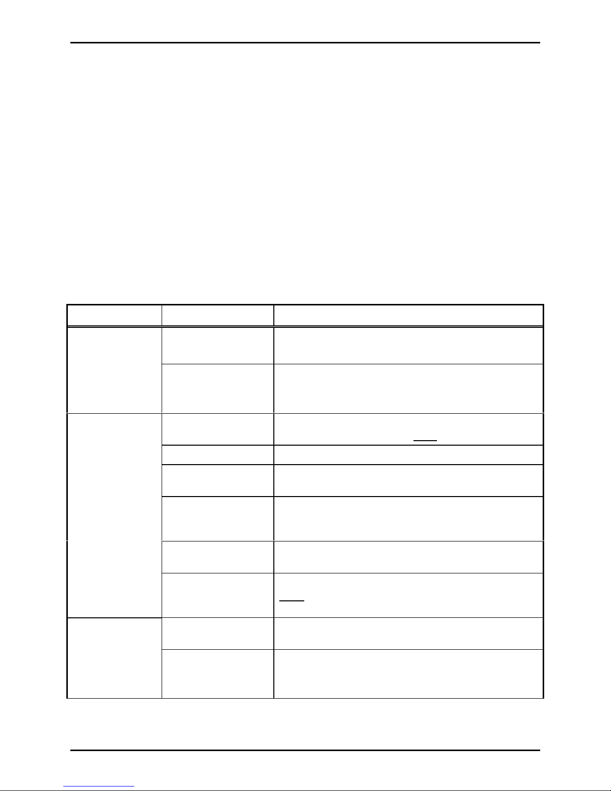
Troubleshooting
Problem: Possible Cause: Possible Solution:
No front panel
POWER ON
indication
No ac power present.
Unit’s ac circuit
breaker is tripped.
• Verify ac power cord is plugged in to ac outlet.
• Verify ac outlet has proper ac voltage available.
• Depress the plunger to reset.
• Check the internal low voltage power supply fuses on
both amplifier boards.
No audio output
Blown internal F1/F2
fuses
Check F1/F2 fuses located on both power amp PCBAs.
CAUTION: Replace with the same type/value fuse.
No input signal source Verify that proper signal/level is being supplied.
Incorrect input signal
connection
Incorrect setting of
25V/70V LINE switch
Verify that the signal input connection is correctly
connected.
If using the line output speaker connections, insure the
25V/70V LINE switch is in the IN position located on the
unit’s rear.
Incorrect output
Check that the output connection has been properly made.
connections
600-ohm/Tel-Page
gain control (rear)
If used, increase level adjustment accordingly.
Note: Both VOLUME and rear gain control affect output
level.
No automatic
Internal jumper setting Check that the internal mute jumper is in the A (enabled)
muting of Hi-Z
input signal
Insufficient 600-ohm/
Tel-Page gain
f:\standard ioms - current release\42004 instr. manuals\42004-340e.doc
06/02
position.
• Check 600-ohm/Tel-Page gain setting.
• Check 600-ohm/Tel-Page audio signal level is
sufficient.
Page 11

Pub. 42004-340E
Model PA250-001 250 Watt Central Amplifier Page: 11 of 12
Problem: Possible Cause: Possible Solution:
Low audio output
Excessive audio
output distortion
plus output PEAK
LED is ON
Excessive static/
electromagnetic
interference
VOLUME setting
• Check VOLUME control setting on front panel.
• Check 600 ohm/Tel-Page gain level setting (rear), if
applicable.
Signal in level Check that adequate input signal level is strong enough.
Input or output
impedance not
Check that the proper input/output line impedance
matches the selected input/output connections used.
matched
Possible low
Check/correct system wiring.
resistance or shorted
wiring across the
audio in and/or across
the speaker OUT
Above normal audio
Reduce input drive signal accordingly.
input drive level
Input and/or output
signal cables may be
routed too close to
• Reroute cables away from high voltage/high
electromagnetic sources.
• Use shielded cables
high voltage/high
electromagnetic
sources
Specifications
Electrical:
Input voltage:....................................................................... 114–126 V ac, 60 Hz only, 120 V ac nominal
Input power consumed (@ nominal V in) (Idle/Full out w/1K tone):......10.9 W, 19.2 VA/514 W, 648 VA
Output power: (with adequate ventilation).................................................250 W
..................with 1 kHz sine in @ 100% duty cycle, derate to ~63 W
@ Ta = +50 °C @ nominal V ac in
RMS
Audio output connections: .......................................................... Direct 8-ohm, Line out 25 V and 70.7 V
Frequency response: (@ rated output)
8-ohm output:................................................................ ~20 Hz - 20 kHz (+0/-3 dB) ref. to 1 kHz
25 V or 70 V line output: ............................................... ~35 Hz - 12 kHz (+0/-1 dB) ref. to 1 kHz
~25 Hz - 20 kHz (+0/-3 dB) ref. to 1 kHz
Total harmonic distortion @ rated output, 1 kHz in, nominal V in:............................................... =/<0.3%
Hum/noise below rated output power:..................................................... –75 dB minimum (un-weighted)
Input sensitivity for rated output: (with front and rear controls CW):
600-ohm (BAL) input:............................................................................... 500 mV
Hi-Z input:................................................................................................ 500 mV
Tel-Page (BAL) input:..................................................................................50 mV
Cont. @ Ta = +24° C
RMS
(maximum)
RMS
(maximum)
RMS
(minimum)
RMS
f:\standard ioms - current release\42004 instr. manuals\42004-340e.doc
06/02
Page 12

Pub. 42004-340E
Model PA250-001 250 Watt Central Amplifier Page: 12 of 12
Input Z of signal inputs:
600-ohm input:................................................................................................ 600 ohm (nominal)
Hi-Z input:.................................................................................................... 10 kilohm (nominal)
Tel-Page (BAL) input:..................................................................................... 600 ohm (nominal)
Start-up delay time:.....................................................................................................2 seconds (nominal)
General:
Temperature range:
Operating:.......................................................................................................... -10º C to +50° C
Storage:.............................................................................................................. -40º C to +85° C
Humidity:...............................................................................................Non-condensing, 85% maximum
External Controls:
Front:............................Main power on/off switch, main ac power circuit breaker, master volume
Rear:.....................600-ohm/Tel-Page input gain control (recessed), 25V/70V LINE in/out switch
External connections (rear):
Audio inputs: 600-ohm/Tel-Page:..............................................................Screw terminals
Dual Hi-Z inputs: ..............................................Paralleled RCA-style jacks
Audio Output: .............................................................. Screw terminals
AC convenience outlet: ................................. Un-switched, grounded receptacle, 2 amp maximum
AC main power cord:...................................................................~6-foot with NEMA 5-15P plug
Front panel LED indicators:.........................................................................POWER ON; Output PEAK
Internal mute jumper (user-defeatable):.....................................................X2 for auto-mute of Hi-Z inputs
Internal fuses: PS DCV Bus {+ and -} (located on both Output Power Amp PCBAs):
F1 and F2.......................................................UL-listed, 5A, 250V, Fast-blow, 0.25 x 1.25 inches
Enclosure:..........................................................................................................................................Steel
Finish: ..............................................................................................................................................Black
Overall unit dimensions:
with feet ........................................................ 19 W × 4.0 H × 13.75 D inches (483 × 101.6 × 349.2 mm)
with feet removed.......................................... 19 W × 3.38 H × 13.75 D inches (483 × 85.8 × 349.2 mm)
Designed for table, shelf, or mounting in standard 19-inch equipment rack (2U high with feet removed)
Unit Weight: .....................................................................................................................26 lbs. (11.8 kg)
Approvals:
UL.................................................................................................................................................UL-813
Part Number Description
12604-015 Replacement Fuse Kit
f:\standard ioms - current release\42004 instr. manuals\42004-340e.doc
06/02
Replacement Parts
 Loading...