

Page 1

Pub. MS05-101iom.2
GAI-TRONICS® CORPORATION
A HUBBELL COMPANY
Model MS05-101
Desktop Master Station
Confidentiality Notice
This manual is provided solely as a n opera tional, installat ion, and ma intenance guide and contains sens itive
business and technical information that is confidential and proprietary to GAI-Tronics. GAI-Tronics
retains all intellectual property and other rights in or to the information contained herein, and such
information may only be used in connection with the opera tion of your GAI -Tronics product or system.
This ma nual may not be disclosed in any form, in whole or in part, directly or indirect ly, to any thir d party.
General Information
The Model MS05-101 Desktop Master Station is designed to operate with the GAI-Tronics MI05-10x
Series Merge/Isolat e Cabinets in a multi-zone Page/P arty
®
communicat ion syst em.
The Model MS05-101 Desktop Master Station can selectively merge and isolate up to five zones that
normally op erate independently. When merged, the zones share a page line and a party line. F or exa mple,
two zones can be merged while the r ema ining z ones are is olated a nd c ontinue to op erate independently.
Voice pages generated from handset s tations within one zone c an be heard in another zone when the two
zones are merged. The Model MS05-101 Master Station controls the actual merging and isolating of the
zones.
Additiona l f eatures a re availab le depending on model of the merge/ isolat e cabinet and the system’s
accessories. Refer to GAI-Tronics publications for the Model MI05-101, MI05-103, and MI05-104
Merge/I solat e C abinets for system and ma ster sta tion capabilities. These include:
• Initia ting voice pa ges to selective zones
• Conduc ting two-way conversat ions with handset s tations
• Monitoring voice pages fr om selective zones
• Merging p age and p arty line channels
• Receiving visual a nd audible call-in signals from handset sta tions
• Activating and res etting a l arm t ones
The MS05-101 Master Station consists of the following components:
• MS05-101S Desktop Subset
• MS05-101A Remote Handset/Speaker Amplifier
• MS05-101E Amplifier Enclosure
GAI-T r onics Corporation 400 E . W y omissing Ave. Mohnt on, PA 19540 USA
610-777-1374 800-492-1212 Fax : 610-796-5954
ISIT WWW.GAI-TRONICS.COM FOR PRODUCT LITERATURE AND MA NUA LS
V
Page 2

Pub. MS05-101iom.2
Model MS05-101 Deskt op M aster S tation Page:
2 of 11
Installation
Mounting and Wiring T erminations
1. Drill or punc h the conduit or cable openings prior t o mounting the amplif ier enclosure. All entr ies to
the amplif ier enclosure should be made from the b ottom or s ides.
OTE: Use caution when drilling holes to avoid damage t o interna l electrical components and wiring.
N
2. Surfa c e mount the amplifier enclosure using the four mounting holes loca ted on the rear of the
enclosure. The amplifier enclosur e can be mounted at a remote location, not to exceed the length of the
15-foot subset cable.
3. Connect all part y lines and the page line wiring t o TB1 and TB2 i n the enc l o sure.
Refer to the Wiring Terminations Table.
4. Connect the RS - 485 data line wiring to TB3 the encl osure.
Refer to the Wiring Terminations Table.
5. If a n ex terna l speaker is used, connect the sp eaker wires to TB1.
• 8-ohm speaker: TB1-4 and TB1-5
• 16-ohm speaker: TB1-4 and TB1-6
6. Plug the 15-f oot ca b l e connector f rom the subset to the socket on the front of the amplifier enclosur e.
7. Connect 120 V ac power conductors t o TB1-1 (H), TB1-2 (N), and TB1-3 (GND) of the amplifier
enclosure.
8. Plug th e ampl i fier int o the enc l o sure a n d tighten t he screw in each c o rner of the a mplif i er.
9. Apply power.
\\86h27g1-fs\iom doc s \ opnot es -- released\mi05-00x merge-is olat e c abs\ms05-101.dir\m s 05-101iom 2.doc
03/09
Page 3

Pub. MS05-101iom.2
Model MS05-101 Deskt op M aster S tation Page:
3 of 11
Connections to the Merge/Isola te Cabinet
1. Locat e the Termi n at i o n PCBA in t h e l o wer lef t corner of the mer g e/is o l at e cabinet .
2. Connect the mast er st ation cable t o TB6 in the cabinet. Refer to the Wiring Terminations Table.
A 9-pair cable (No. 18–20 AWG) is recommended for this connection.
Wiring Terminations Table
Terminals
Master Station Merge/Isolate Cabinet
Function
TB3-23 and TB3-24 TB6-1 and TB6-2 RS-485 data line (+ /-)
TB3-25 TB6-3 Data ground
TB1-10 and TB1-11 TB6-5 and TB6-6 Page monitor (See note.)
TB1-8 and TB1-9 TB6-7 and TB6-8 Page line (See note.)
TB2-12 and TB2-13 TB6-9and TB6-10 Party Line 1
TB2-14 and TB2-15 TB6-11 and TB6-12 Party Line 2
TB2-16 and TB2-17 TB6-13 and TB6-14 Party Line 3
TB2-18 and TB2-19 TB6-15 and TB6-16 Party Line 4
TB2-20 and TB2-21 TB6-17 and TB6-18 Party Line 5
N
OTE: If connecting to Model MI05-101 Merge/Isolate Cabinet, jumper the page line (TB1-8 and
TB1-9) to the page monitor line (TB1-10 and TB1-11). If these lines are not tied together, the master
station sp eaker w ill not br o adc as t .
\\86h27g1-fs\iom doc s \ opnot es -- released\mi05-00x merge-is olat e c abs\ms05-101.dir\m s 05-101iom 2.doc
03/09
Page 4
Pub. MS05-101iom.2
Model MS05-101 Deskt op M aster S tation Page:
Setting the Station’s Address
4 of 11
Eac h ma ster sta tion in the sys tem requir es a uniqu e address. If two mas ter stations have the same address,
data collision will occ ur when communicating with the merge/isolat e cabinet, resulting in a f ault c ondition.
The master station addresses must be set in sequence starting at 1. Do not skip any numbers when
assigning addresses .
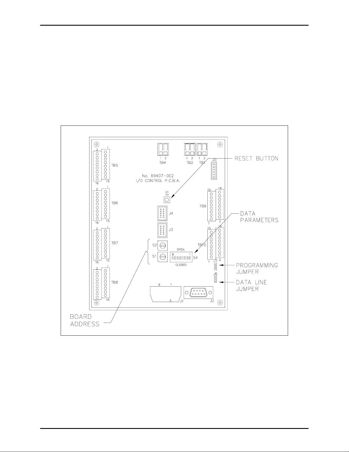
The I/ O control board is located ins ide t he desktop subset . This determines t he s tation address and als o
controls the s tat ion’ s zone and alarm selection fea tur es by scanning the switches a nd then transmitting the
selection to the merge/isolate ca b i net over a data line. There are sever al switc hes and jumper s on the I/O
board that must be set correctly for the station to operate correctly. Refer to Figure 1 below for I/O
contr oller boa rd out line and switc h locations.
Figure 1. I /O Controller B oard
Switches S1 and S2
S1 and S2 are hexadecimal s witches that are used to set the I/O board’s address. If the sys tem contains
more tha n one ma ster station, each st ation’ s I/O board must be set wit h a different sequential addres s
starting with 01 . Swit c h S2 sets the first digit and switch S1 sets the second digit.
\\86h27g1-fs\iom doc s \ opnot es -- released\mi05-00x merge-is olat e c abs\ms05-101.dir\m s 05-101iom 2.doc
03/09
Page 5

Pub. MS05-101iom.2
Model MS05-101 Deskt op M aster S tation Page:
Switch Setting Examples
5 of 11
Switch
S2
Switch
S1
Master Station
Address
0 1 1
0 2 2
0 3 3
0 4 4
0 5 5
0 6 6
0 7 7
0 8 8
OTE: The fact ory defa ult set ting is 0 1 since typically there is only one master sta tion per system.
N
OTE: The switch set ting is recognized only when eit her t h e I/O Contro l l er is powered up, o r when the
N
ESET button is pressed. Momentarily press the RESET button each time a switch is c hanged.
R
DIP Switch Settings
The I/O controller switch S4 is an 8-position DIP switch that is used to set the data baud rate. This switch
is fa c tory set and should not be changed. If rep lacing the I /O controller, be su re to set the swit c h as
follows:
Figure 2. S4 DIP Switch
Switch Position Open/Close Switch Position Open/Close
S4-1 Open S4-5 Open
S4-2 Open S4-6 Close
S4-3 Open S4-7 Close
S4-4 Open S4-8 Open
Momentarily press the R
\\86h27g1-fs\iom doc s \ opnot es -- released\mi05-00x merge-is olat e c abs\ms05-101.dir\m s 05-101iom 2.doc
03/09
ESET button eac h time a swit c h is changed.
Page 6

Pub. MS05-101iom.2
Model MS05-101 Deskt op M aster S tation Page:
Operation
ALARMS
ZONE SELECT
6 of 11
Figure 3. Model MS05-101S Desktop Master Subset Outline
Merging Zones
When merged, the s tat ions in each zone share a page line and party line 1. Voic e p ages generated from
handset stations within one zone can be hear d in another z one when t he t wo z ones are merged. Party line 1
can also b e u sed to condu c t a two-way c onversation bet ween zones .
It is possible to merge some zones while the remaining zones are isolated. Complete the following st ep s to
merge zones:
1. Select t he desired Z
group of zones, or all zones. The green LE D indicators loc ated a bove each selected zone push button
illuminate.
2. Press the MERGE push button.
3. To isol at e the zon es, press the MERGE pu sh button again followed by the Z
push button.
OTE: If the ALL push button is pressed, it merges all z ones aut oma tica lly— the MERGE push button
N
does not also need to be p ressed. To isolat e t he zones , press the Z
ONE SELECT push buttons (1 through 5 or ALL). This could be two zones, a
ONE SELECT RESET
ONE SELECT RESET push button.
\\86h27g1-fs\iom doc s \ opnot es -- released\mi05-00x merge-is olat e c abs\ms05-101.dir\m s 05-101iom 2.doc
03/09
Page 7

Pub. MS05-101iom.2
Model MS05-101 Deskt op M aster S tation Page:
Communicati on on Party Line 1
The mas ter s tat ion c an select ively communicate wit h f ield sta tions in eac h z one, or wit h other master
stations. T o c ommunicate with a field st ation:
7 of 11
1. Lift the handset and select party line 1 on t he P
2. Select t he desired Z
ONE SELECT push button (1 through 5 or ALL). This c ould be a single zone, a
ARTY LINE rotary selector switch.
group of zones, or all zones. The green LED indicator(s) above the selected zone(s) illuminates.
3. Press the MERGE p ush button. T wo- way communica tion with handsets stations in the selected zones
is now available.
4. When conversation is c omplet e, press the Z
ONE SELECT RESET push button.
The zone switches are not needed to communicate with ot her master stations. Simply lift the handset and
select party line 1 on the P
ARTY LINE selector switch. Two-way communica tion with ot her master stations
is now available.
Communicati on on Party Lines 2 through 5
Communication between the Model MS05-101 Master Station and field stations is not available unless
each zone’s party lines 2 thr ough 5 a nd the mast er station p arty lines 2 throu gh 5 are c onf igured a s
“common.” This is accomplis hed b y ju mp er sett ings on the T ermination PCBA inside t he merge/ isolat e
cab inet. J umpers are p rovided for party lines 2 throu gh 5 in each zone and for the mast er st ation p arty
lines. R efer to t he Ins tallation section of the merge/isolat e cabinet ma nual for jumper setting det ails.
Ass uming the par ty lin es are s et to common
, communicate on part y lines 2 thr ough 5 from the master
station t o f ield sta tions a s follows:
Lift the mast er station handset and select a part y line ( 2 thr ough 5) on t he P
ARTY LINE selector switch.
Two-way communica tion with ot her master s tat ions and handsets stations in zones 1 throu gh 5 is now
available.
Paging to Other Master Sta tions
To generate a page t o other master sta tions, lift the handset, pr ess the handset p ressbar, and speak directly
into the microphone. The pa ge message is broadc ast from sp eakers at all the other master stat ions. If
two-wa y, part y line (full dup lex ) communicat i on is desired, relea se the hands et pressba r to connec t to the
selected pa rty line.
\\86h27g1-fs\iom doc s \ opnot es -- released\mi05-00x merge-is olat e c abs\ms05-101.dir\m s 05-101iom 2.doc
03/09
Page 8

Pub. MS05-101iom.2
Model MS05-101 Deskt op M aster S tation Page:
Paging to Field Sta tions
To page to field s tations, c omp let e t he following steps :
8 of 11
1. Select t he desired Z
ONE SELECT push buttons (1 through 5 or ALL). This could b e one zone, a group
of zones, or all z ones . The green LED indicator(s) f or the select ed zone(s) illumina te.
2. Lift the handset, press the handset pr es sba r, and sp eak directly into the microphone. The page message
is broadcast f rom spea kers in t he s elect ed zones .
3. To reset the system, press the Z
OTE: If the ALL push button is pressed, it merges a ll z ones aut oma tically. To reset t he zones , press t he
N
ONE SELECT RESET push button.
Z
ONE SELECT RESET push button.
Speaker Volume Control
Use t h e VOLUME knob on the Model MS05-101S Desktop Master Station Subset to adjust the front panel
spea ker volume. Tur ning the knob clockwis e increas es the sp eaker volume, and tu rning it counterc loc kwise
decreases the volume.
The front panel volume control does not affect any external speaker tha t is connect ed to the master s tat ion.
The sp eaker volume for any externally-mounted spea kers is c ontrolled using the amplif ier volume contr ol
locat ed u nder the GAI- Tronics nameplate on the f ront of the amplifier.
OTE: A small screwdr iver is r equired for ma king this a dju stment.
N
Fault Indi cators
Two t yp es of indica tion are pr ovided for data communication f aults bet ween the master sta tion(s) and the
merge/is olate cabin et.
1. If data communication los t between a ma ster sta tion and t he merge/ isolat e cabinet, all the LED
indicat ors on t he affected master sta tion sub set su bset will flash. All alarm and zone select ion f eatures
are disabled during this type of fault. Party line communication on party lines 2–5 is unaffected.
Pa ging is still p ossible t o other master sta tions.
2. The red FAULT indicator on the subset is only f unctional when multiple mas ter stat ions are installed in
the system. When th e FAULT indicator illuminates there is a data f ault between the merge/isolate
cab i net and one of the ot her master s tat ions in the system. It does not
indicate a data fault at the local
master station.
Possible causes of data fault conditions include:
• A defective master I/O controller b oard in the merge/isolate ca binet.
• Improp er s wi tch setting o f the master cont roll er s w i tches in the merg e/is o l at e cabinet;
• Missing or reversed data c able connection between a ma ster sta tion and t he merge/ isolate cab inet .
• A defective I/ O c ontroller board in a master st ation.
\\86h27g1-fs\iom doc s \ opnot es -- released\mi05-00x merge-is olat e c abs\ms05-101.dir\m s 05-101iom 2.doc
03/09
Page 9

Pub. MS05-101iom.2
Model MS05-101 Deskt op M aster S tation Page:
9 of 11
Lamp T est/ R eset
Momentarily press the red push button located on the back of the Model MS05-101 Master Station. All
LEDs should momentarily illuminate. T his action als o resets the I/O controller .
Optional F eatures
These op tions are availa ble only wh en the a ppl i cable kits ar e i n stalled i n the mer g e/is o l at e cabinet.
Depending on the merge/is olate ca binet installed in the system, not all the featur es may be availabl e.
Activati ng an Alarm
NOTE: This feature is only available if a Model 10959-101 or 10959-104 Audio Messenger Interface is
connected to the syst em merge/is olate cabinet.
Alar ms c an be a utomat i c ally broadcast to all zones when activated (automa tic), or can be manu ally routed
to broadcast to a ny c ombination of zones or all zones (selective).
For selective alarm routing, complete the following steps to activate an alarm from a master station:
1. Select t he desi red alarm dest ination u sing the Z
ONE SELECT push buttons (1 through 5 or ALL). The
destination coul d be a single zone, a group of z ones , or all zones. The green LED indicators for the
selected zones illumina te.
2. Press the MERGE push button.
3. Select the a pprop riate ALARM pus h but ton (1 throu gh 7).
The a larm is broadcast int o the selected zones and fr om the ma ster sta tion speaker. The red L ED
indicat or for the selected alarm switch illuminates during the broadcast.
4. To cancel an alarm, press the A
OTE: The zones r emain merged. To i solate the zo n es, pr ess the MERGE pu sh button a gain
N
followed by the Z
ONE SELECT RESET push button.
LARM RESET push button.
For automatic alarm routing to all zones, complete the following steps to activate an alarm from a master
station:
1. Select the a pprop riate ALARM pus h but ton (1 throu gh 7).
The a larm broadc asts into the all zones and fr om t he master sta tion speaker. The red LED indica tor
for t he s elect ed alarm switch illuminates du ring the broadc ast.
2. To cancel an alarm, press the A
OTE: The z o n es r emain merged. To i solate the zon es, press the ZONE SELECT RESET push
N
LARM RESET push button.
button.
\\86h27g1-fs\iom doc s \ opnot es -- released\mi05-00x merge-is olat e c abs\ms05-101.dir\m s 05-101iom 2.doc
03/09
Page 10

Pub. MS05-101iom.2
Model MS05-101 Deskt op M aster S tation Page:
Call-In Signaling
NOTE: This feature is only available when using the Model MI05-104 Merge/Isolate Cabinet.
10 of 11
The Call-In s i gnaling featur e (also known as Of f - hook Detection) provides a means to signa l the mast er
station operator t hrough audible and visual indica tors . When a Page/ Party
®
handset station in any zone
goes off hook on p arty line 1, the mast er station is signaled in t wo ways: t he s onalert sounds and the zone’s
call-in L ED indica tor illuminates yellow. When t he op erator answers t he call, t he s onalert is turned off.
Pressing the S
The S
ONALERT ON/OFF pu sh button does not reset for each c all-in. I f the sonalert is tur ned off , it
ONALERT ON/OFF p u sh button a l so silences t he sonalert.
remains off until it is manually t u rned on by pressing the button again.
Page Monitoring
NOTE: This feature is only available when using the Model MI05-103 and MI05-104 Merge/Isolate
Cabinets.
The Page Monit oring feature allows the operator of the master s tat ion to selectively monitor voice paging
in any or all zones. The page lines are monitored via the integral s peaker on the mast er station’ s sub set.
When the master s tation operator presses a zone pu sh button, pa ges f rom tha t zone are br oadcast f rom the
mast er station’ s speaker. The operator ca n monit or more than one zone by select ing any combina tion of
zone pus h but tons. To montor zones:
1. Select t he desired Z
zones, or all z ones . The green LED indicator s for the selected zones illu mina te.
OTE: Do not press the ALL but ton when monitoring z ones . This au tomatic ally merges t he z ones .
N
ONE SELECT push buttons (1 through 5). This cou l d be two zones, a group of
2. Press the Z
ONE SELECT RESET push b utton to discontinue monitori ng.
Maintenance
If the equip ment requir es service, c ontact your Regional S ervice Center for a ret urn authoriza tion number
(RA# ) . Equi pment should b e s hipped prepai d to GAI-Tronic s with a retu rn author iz ation number a nd a
purchas e order nu mber. If the equipment is u nder warra nty, repairs or a replac ement will be made in
accordanc e with GAI-Tronic s’ warranty p olic y. Please include a written explanation of a ll defects t o ass ist
our technicia ns in their trou bleshooting eff orts .
Call 800-492-1212 inside the USA or 610-777-1374 outside the USA for help identifying the Regional
Servic e Center closest to you.
\\86h27g1-fs\iom doc s \ opnot es -- released\mi05-00x merge-is olat e c abs\ms05-101.dir\m s 05-101iom 2.doc
03/09
Page 11

Pub. MS05-101iom.2
Model MS05-101 Deskt op M aster S tation Page:
Supplemental Information
For additional information, please reference the drawings listed below.
• 73530 MS05-101 Ma ster Stat ion Outline Drawing
• 73531 MS05-101S Desktop Subset Outline and Connection Diagram (2 sheets)
• 73532 MS05-101A Handset/Speaker Amplifier Outline and Connection Diagram
• 73534 MS05-101E Amplifier Enclosure Outline and Connection Diagram
Spare Parts List
Part No. Description
MS05-101A Remote Handset/Speaker Amplifier
69286-101 Switch/LED PCBA
69407-002 I/O Controller PCBA
10112-101 Handset Assembly, with 6-foot cord
11 of 11
\\86h27g1-fs\iom doc s \ opnot es -- released\mi05-00x merge-is olat e c abs\ms05-101.dir\m s 05-101iom 2.doc
03/09
 Loading...