

Page 1

Pub. MI05-101iom.2
G A I - T R O N I CS ® C O R P O R A T I O N
A H U B B E L L C O M P A N Y
Model MI05-101
Merge/Isolate Cabinet
Confidentiality Notice
This manual is provided solely as an operation, installation, and maintenance guide and contains sensitive
business and technical information that is confidential and proprietary to GAI-Tronics. GAI-Tronics
retains all intellectual property and other rights in or to the information contained herein, and such
information may only be used in connection with the operation of your GAI-Tronics product or system.
This manual may not be disclosed in any form, in whole or in part, directly or indirectly, to any third
party.
General Information
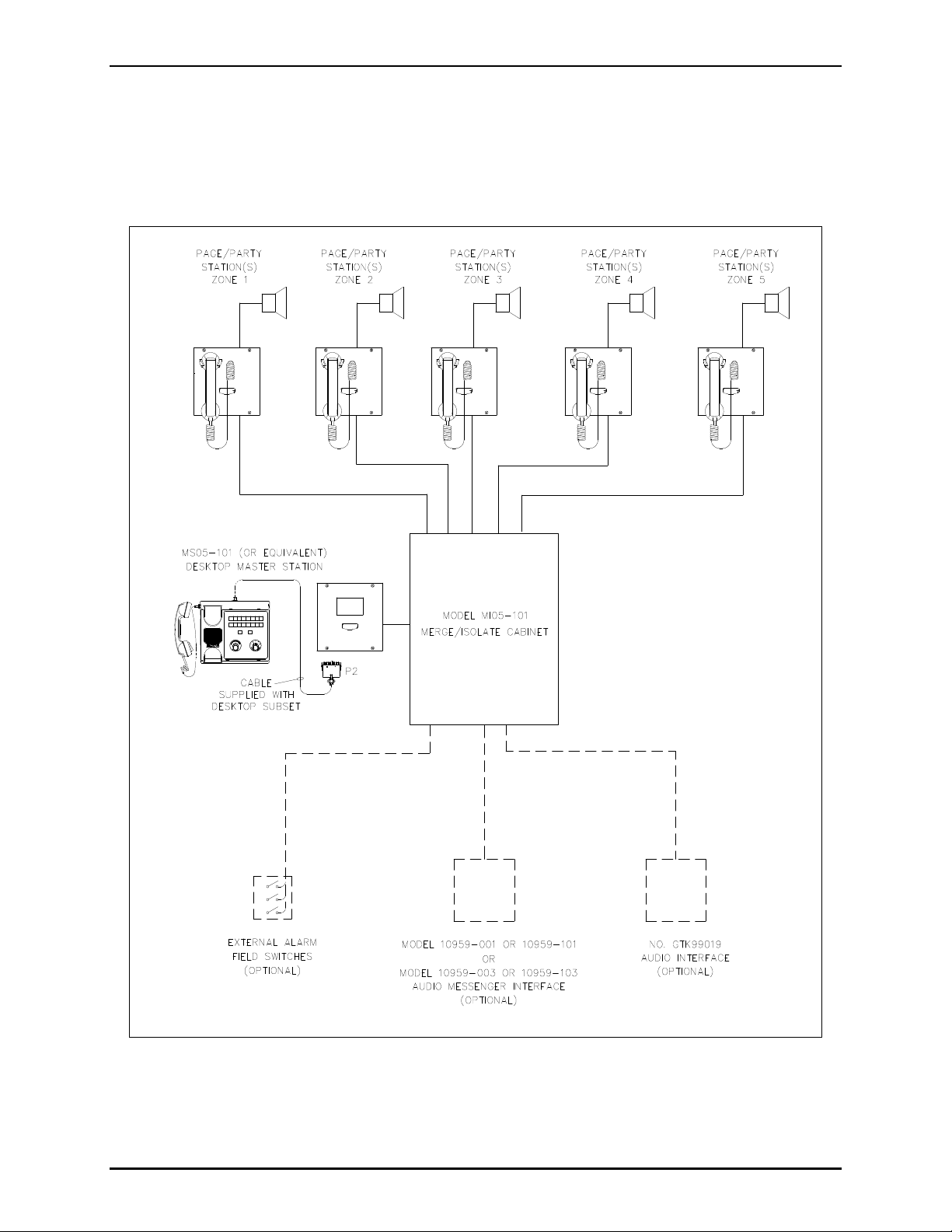
The Model MI05-101 Merge/Isolate (M/I) Cabinet is designed to operate in a multi-zone Page/Party
communication system. The cabinet can selectively merge and isolate up to five zones that normally
operate independently. Each zone’s Page/Party®communication cable, which contains five party lines
and one page line, is connected to the M/I cabinet.
®
When merged, the zones share a page line and a party line. For example, two zones can be merged while
the remaining zones in the system are isolated and continue to operate independently. Voice pages
generated from handset stations within one zone can be heard in the other zone when the two zones are
merged. The actual merging and isolating of the zones is controlled by a GAI-Tronics Model MS05-101
Master Desktop Station (or equivalent), which works in conjunction with the cabinet. The cabinet supports
a maximum of eight master stations.
In addition to merging and isolating the system zones, the cabinet can also perform other functions when
equipped with the following accessories, all of which can be added at any time:
MS05-101 Master Desktop Station or equivalent — a Page/Party®handset station that also provides
the capability for an operator to direct the merging and isolating of zones and manual initiation of
alarms when used in conjunction with the M/I cabinet.
10959-101 Audio Messenger Interface (AMI) — a microprocessor-controlled tone/speech generator
that produces alarm tones (with speech messages) to alert people of emergency conditions.
10959-103 Audio Messenger Interface with Telephone Interface — provides the same features and
functions as the Model 10959-101 described above, but adds telephone interface circuits to allow
telephone users the ability to make voice pages and to communicate with handset stations in the
Page/Party®system on party line 5.
GTK99019 Audio Interface — allows other audio sources, such as 2-way radio equipment, to be
connected to the system.
GAI-Tronics Corporation 400 E. Wyomissing Ave. Mohnton, PA 19540 USA
610-777-1374 800-492-1212 Fax: 610-796-5954
VISIT WWW.GAI-TRONICS.COM FOR PRODUCT LITERATURE AND MANUALS
Page 2
Pub. MI05-101iom.2
Model MI05-101 Merge/Isolate Cabinet Page: 2 of 24
Alarm Activation Switches — allows external switch or relay contacts to activate the AMI. (The
AMI must be connected).
GTD99001-VLCX Volume Level Control Transmitter—provides activation of remote devices using
existing system cable. This kit can be used to activate strobe lights via other devices or mute and
un-mute speakers at Page/Party®stations.
Figure 1. Typical Block Diagram
\\86h27g1-fs\iomdocs\opnotes -- released\mi05-00x merge-isolate cabs\mi05-101.dir\mi05-101iom2.doc
01/09
Page 3
Pub. MI05-101iom.2
Model MI05-101 Merge/Isolate Cabinet Page: 3 of 24
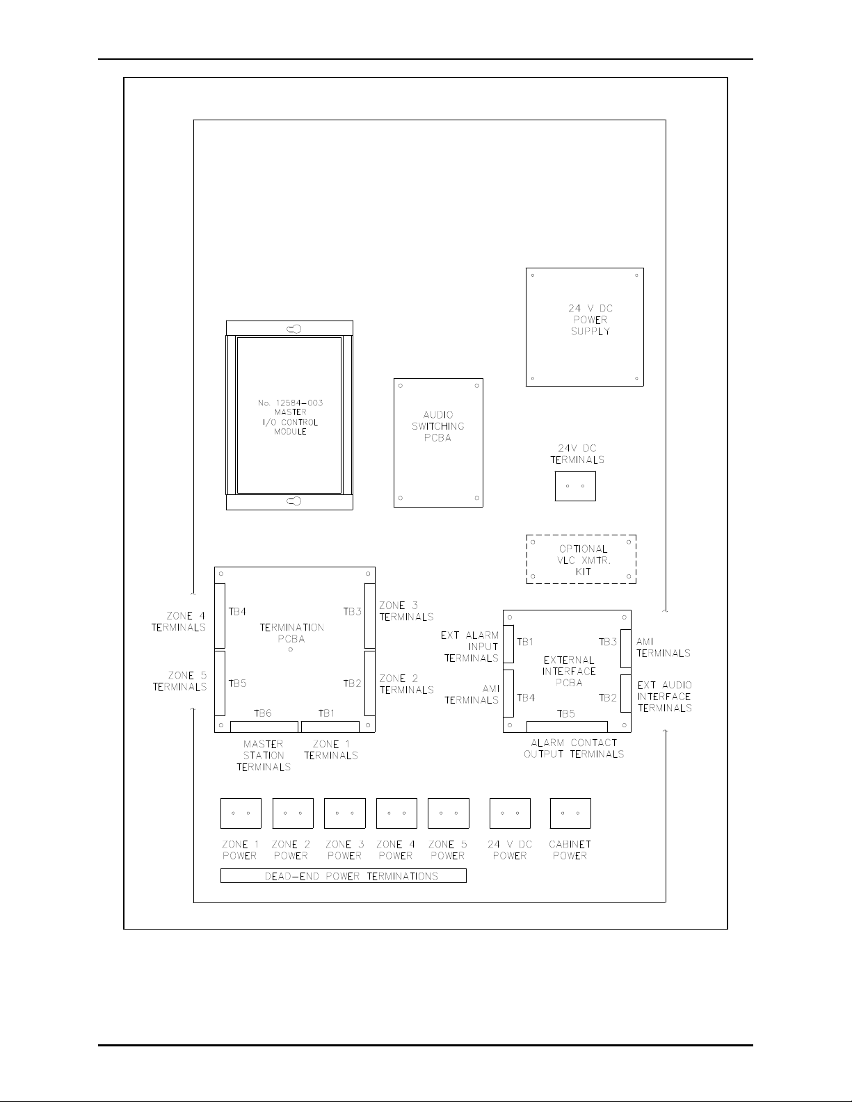
Figure 2. Merge/Isolate Cabinet Component Locations
\\86h27g1-fs\iomdocs\opnotes -- released\mi05-00x merge-isolate cabs\mi05-101.dir\mi05-101iom2.doc
01/09
Page 4
Pub. MI05-101iom.2
Model MI05-101 Merge/Isolate Cabinet Page: 4 of 24
Installation
NOTE: All system line balancing is located in this cabinet; therefore, any existing page and party line
balance assemblies must be removed when the Model MI05-101 Merge/Isolate Cabinet is installed.
Cabinet Mounting
Mount the M/I cabinet in a secure area that is protected from adverse environmental conditions such as
rain, heavy dust, excess moisture, and temperature extremes. For optimum performance, mount the
cabinet no farther than one mile from the farthest Page/Party®station. Mount the enclosure to the wall by
installing four mounting bolts through the predrilled holes in the rear of the enclosure.
Field Wiring
All terminations are made to the Termination PCBA using modular terminal block connections. Each
connection is labeled inside the M/I cabinet.
Connecting FieldStations
1. Locate the Termination PCBA in the lower left corner of the cabinet. See Figure 2.
2. Connect all page and party lines from each of the zones to the appropriate terminals on the
Termination PCBA. GAI-Tronics 60038 Series single party cable or 60029 Series multi-party cable
is recommended.
TB1 Zone 1 field stations
TB2 Zone 2 field stations
TB3 Zone 3 field stations
TB4 Zone 4 field stations
TB5 Zone 5 field stations
3. Make the following connections:
Terminals
Field Stations Merge/Isolate Cabinet
Function
TB1-8 and TB1-9 TBx-1 and TBx-2 Page
TB2-12 and TB2-13 TBx-3 and TBx-4 Party Line 1
TB2-14 and TB2-15 TBx-5 and TBx-6 Party Line 2
TB2-16 and TB2-17 TBx-7 and TBx-8 Party Line 3
TB2-18 and TB2-19 TBx-9 and TBx-10 Party Line 4
TB2-20 and TB2-21 TBx-11 and TBx-12 Party Line 5
Refer to the manual for the custom
TBx-13 and TBx-14 Merge
station for terminal block numbers.
x = Applicable zone
\\86h27g1-fs\iomdocs\opnotes -- released\mi05-00x merge-isolate cabs\mi05-101.dir\mi05-101iom2.doc
01/09
control
Page 5
Pub. MI05-101iom.2
Model MI05-101 Merge/Isolate Cabinet Page: 5 of 24
If using GAI-Tronics system cable to connect field stations, terminate the ac power conductors to the
terminal blocks provided at the bottom of the cabinet. Three terminal blocks are provided for each zone.
The ac power conductors are color-coded black (H), white (N), and green (GND).
NOTE: These terminals do not provide power to the field station. The terminals are provided only for
convenience in terminating the system cable power conductors.
Connecting ModelMS05-101 Desktop MasterStations (orequivalent)
1. Locate the Termination PCBA in the lower left corner of the cabinet. See Figure 2.
2. Connect the desktop master station to TB6 in the cabinet. The recommended cable for this
connection is a 9-pair cable.
3. Make the following connections:
Terminals
Master Station Merge/Isolate Cabinet
Function
TB3-23 and TB3-24 TB6-1 and TB6-2 RS-485 data line (+/-)
TB3-25 TB6-3 Data ground
TB1-10 and TB1-11 TB6-5 and TB6-6 Page monitor
TB1-8 and TB1-9 TB6-7 and TB6-8 Page
TB2-12 and TB2-13 TB6-9 and TB6-10 Party Line 1
TB2-14 and TB2-15 TB6-11 and TB6-12 Party Line 2
TB2-16 and TB2-17 TB6-13 and TB6-14 Party Line 3
TB2-18 and TB2-19 TB6-15 and TB6-16 Party Line 4
TB2-20 and TB2-21 TB6-17 and TB6-18 Party Line 5
\\86h27g1-fs\iomdocs\opnotes -- released\mi05-00x merge-isolate cabs\mi05-101.dir\mi05-101iom2.doc
01/09
Page 6
Pub. MI05-101iom.2
Model MI05-101 Merge/Isolate Cabinet Page: 6 of 24
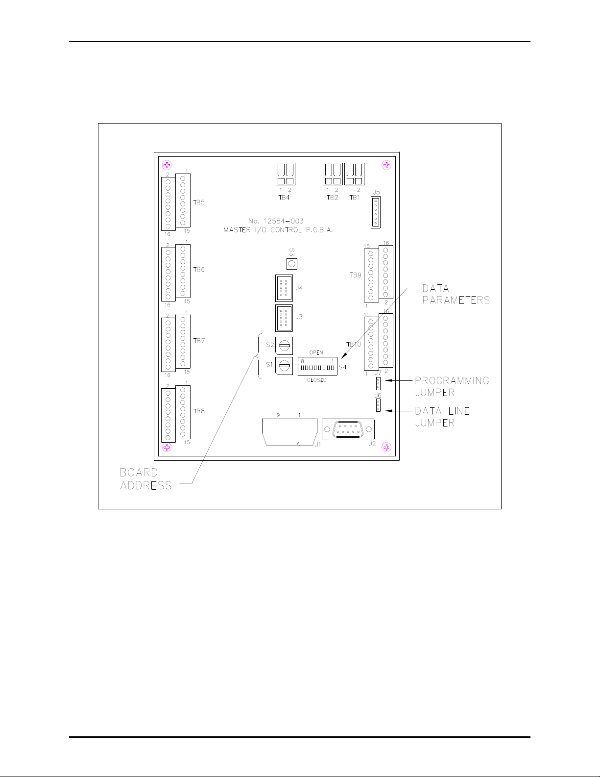
Master I/O Controller Switch Settings
The Master I/O Controller contains two hex switches labeled ADDRESS ID on the cover. Refer to
Figure 3. These switches must be set to identify the number of master stations in the system. This
setting is critical to ensure the Master I/O Controller recognizes the commands from all the master
stations. Up to eight master stations can be parallel-connected to the M/I cabinet.
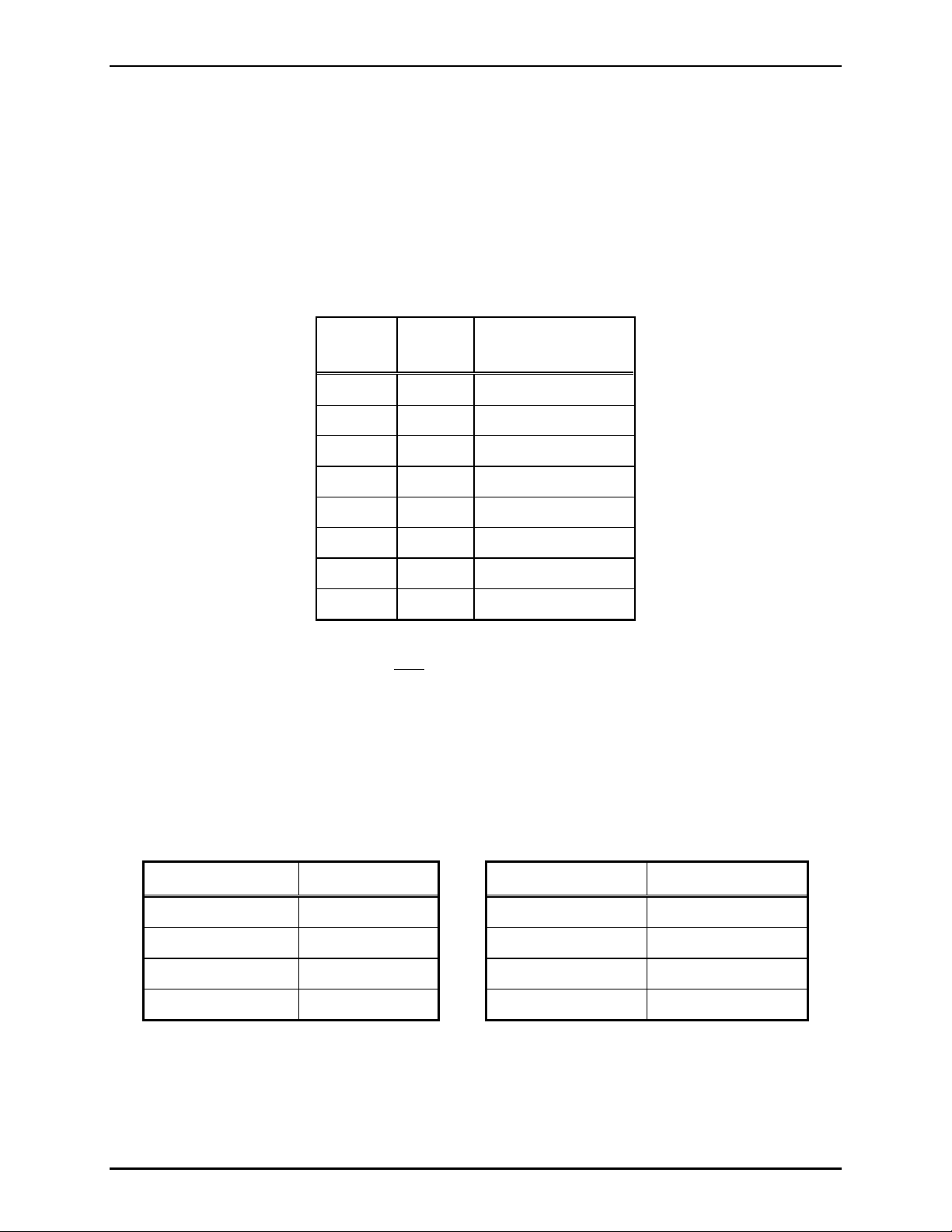
Switches S1 and S2 are used to set the number of master stations in the system. The switch setting is
read as a hexadecimal number. Switch S1 is the LO address and switch S2 is HI address.
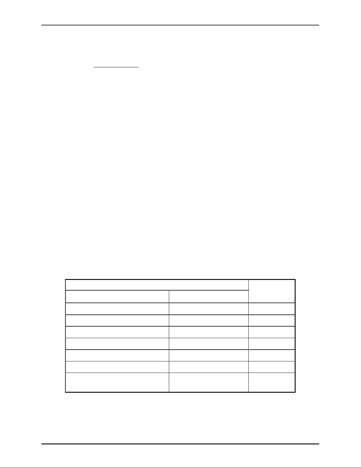
Switch Setting Examples
SwitchS2Switch
S1
Number of
Master Stations
0 1 1
0 2 2
0 3 3
0 4 4
0 5 5
0 6 6
0 7 7
0 8 8
NOTE: The switch setting is recognized only when either the Master I/O Controller is powered up, or
when the RESET button is pressed. Momentarily press the RESET button each time a switch is changed.
The RESET button located next to the ADDRRESS ID switches.
DIP Switch Settings
The Master I/O controller switch S4 is an 8-position DIP switch that is used to set the data baud rate.
This switch is factory set and should not be changed. To access the DIP switch, the cover must be
removed from the I/O controller. If replacing the Master I/O controller, be sure to set the switch as
follows:
Switch Position Open/Close Switch Position Open/Close
S4-1 Open S4-5 Open
S4-2 Open S4-6 Open
S4-3 Open S4-7 Open
S4-4 Open S4-8 Close
Press the RESET switch following any switch changes.
JumperClipSettings
The Master I/O controller has two jumper clips, J6 and J7, which determine the data connection and
operating mode of the module, as follows:
\\86h27g1-fs\iomdocs\opnotes -- released\mi05-00x merge-isolate cabs\mi05-101.dir\mi05-101iom2.doc
01/09
Page 7
Pub. MI05-101iom.2
Model MI05-101 Merge/Isolate Cabinet Page: 7 of 24
J6 –is a 3-position jumper that selects either RS-232 or RS-485 data communication. Always select
RS-485 by inserting the shorting clip across pins 2 and 3 on J6.
J7 –is a 3-position jumper that puts the board in programming mode. Always select run mode by
inserting the shorting clip across pins 1 and 2 on J7.
Figure 3. Master I/O Controller Module (Cover removed)
\\86h27g1-fs\iomdocs\opnotes -- released\mi05-00x merge-isolate cabs\mi05-101.dir\mi05-101iom2.doc
01/09
Page 8

Pub. MI05-101iom.2
Model MI05-101 Merge/Isolate Cabinet Page: 8 of 24
FaultLightIndicator
The red LED indicator on the Audio Switching PCBA illuminates if data communication is lost to any of
the master stations.
AlarmMode Jumper
At the master I/O controller module, a jumper is pre-installed at the factory between terminals 15 and 16
at TB8. The following describes the modes of operation if the jumper is installed or removed:
Installed (manual alarm routing) –With the jumper installed, any alarm activation at the master or at
an external input will cause the AMI to become active, but the alarm audio will be broadcast only to the
master station(s). This feature allows the master station operator to direct the alarm audio to the zone(s)
affected by the alarm event.
Removed (automatic All-Zone alarm) –If the is jumper removed, any alarm activation at the master or
at an external input will cause the AMI to become active, and also automatically route the alarm audio to
all zones. The master operator can intervene and deselect zone(s) not affected by the alarm event.
Setting Jumpers and Adjustments
LineBalance Adjustment for Page Lines
A line balance adjustment is provided for each zone and the master stations. The line balance adjustment
is factory-set for optimum performance but may need adjustment in some situations. If the line balance
adjustment is set too low, the speaker volume will also be low. If the line balance adjustment is set too
high, the speaker audio will be distorted. To correct low or distorted audio, complete the following
adjustments.
Master Stations
Perform the following steps to properly adjust the line balance assembly:
1. Remove the page line conductors from terminals 7 and 8 on the Termination PCBA. See Figure 2
for terminal block location for the master station.
2. Place an ohmmeter across terminals 7 and 8 on the Termination PCBA.
NOTE: The optimum page line balance is 33 ohms.
3. Adjust potentiometer R15 on the Audio Switching PCBA to achieve 33 ohms on the ohmmeter.
Field Stations
Perform the following steps to properly adjust the line balance assembly for all zones:
1. Remove the zone page line conductors from terminals 1 and 2 on the Termination PCBA. See Figure
2 for the terminal block location for each zone.
2. Place an ohmmeter across terminals 1 and 2 on the Termination PCBA.
NOTE: The optimum page line balance is 33 ohms.
\\86h27g1-fs\iomdocs\opnotes -- released\mi05-00x merge-isolate cabs\mi05-101.dir\mi05-101iom2.doc
01/09
Page 9

Pub. MI05-101iom.2
Model MI05-101 Merge/Isolate Cabinet Page: 9 of 24
3. Adjust the applicable potentiometer on the Audio Switching PCBA for each zone to achieve a
reading of 33 ohms on the ohmmeter. Refer to the chart below for the correct potentiometer for each
zone.
Zone Potentiometer
Zone 1 R2
Zone 2 R5
Zone 3 R8
Zone 4 R11
Zone 5 R17
LineBalance for Party Lines
The Model MI05-101 Merge/Isolate Cabinet provides line balancing for all system party lines. No user
adjustments are required for the party lines unless the party lines are made common and an external
device such as the Model 10959-103 Audio Messenger Interface with telephone interface circuits, or the
Model GTK99019 External Audio Interface, is used with the system. If party line 4 and/or 5 is used for
either the Audio Messenger Interface or the External Audio Interface, the line balance must be removed
because each device provides the necessary line balancing for the designated party line.
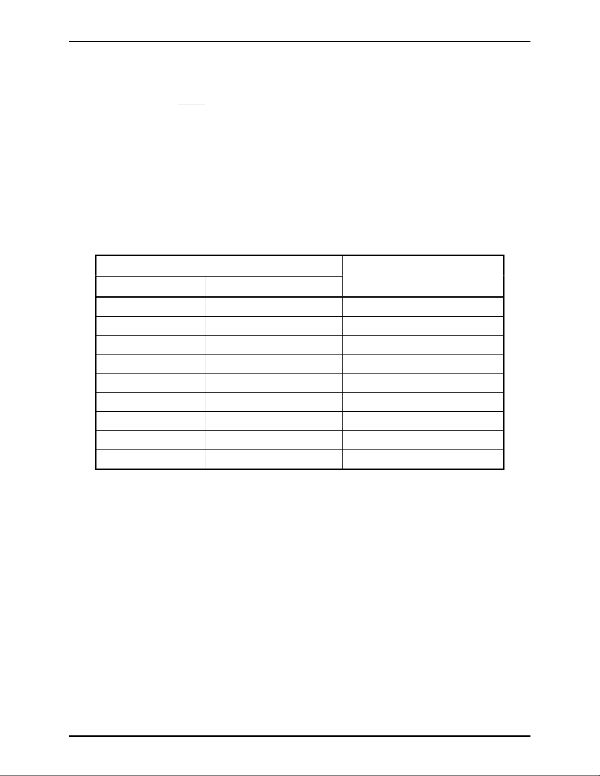
To disable the internal line balance for either party line 4 and/or 5, refer to the following table:
Party
Line Jumpers
Internal Line Balance
Enable
Disable
Internal Line Balance
4 JB51 and JB52 Jumper pins 1 and 2 Jumper pins 2 and 3
5 JB53 and JB54 Jumper pins 1 and 2 Jumper pins 2 and 3
\\86h27g1-fs\iomdocs\opnotes -- released\mi05-00x merge-isolate cabs\mi05-101.dir\mi05-101iom2.doc
01/09
Page 10

Pub. MI05-101iom.2
Model MI05-101 Merge/Isolate Cabinet Page: 10 of 24
Enable/Disable the Call-In Feature
Jumpers are provided on the Termination PCBA to
enable or disable the Call-In feature for each zone.
Zone Call-In Feature Jumpers
1 JB1 and JB2
To enable the Call-In feature, jumper pins 2 and 3
on the Termination PCBA.
2 JB3 and JB4
3 JB5 and JB6
To disable the Call-In feature, jumper pins 1 and 2
on the Termination PCBA.
4 JB7 and JB8
5 JB9 and JB10
ConfiguringCommon Party Lines between Zonesand Master Station
Jumpers are provided on the Termination PCBA to make party lines 2 through 5 common across zones
and the master station(s). When a party line is made common between zones and the master station, any
station can pick up a handset and join the conversation.
To make a party line common, jumper pins 1 and 2 on the jumper assigned to the zone or master
station party line.
To isolate the party line, jumper pins 2 and 3 on the jumper assigned to the zone or master station
party line.
The following table lists the jumpers for each zone.
Zone Party Line 2 Party Line 3 Party Line 4 Party Line 5
1 JB11 and JB12 JB13 and JB14 JB15 and JB16 JB17 and JB18
2 JB19 and JB20 JB21 and JB22 JB23 and JB24 JB25 and JB26
3 JB27 and JB28 JB29 and JB30 JB31 and JB32 JB33 and JB34
4 JB35 and JB36 JB37 and JB38 JB39 and JB40 JB41 and JB42
5 JB43 and JB44 JB45 and JB46 JB47 and JB48 JB49 and JB50
Master N/A N/A JB51 and JB52 JB53 and JB54
\\86h27g1-fs\iomdocs\opnotes -- released\mi05-00x merge-isolate cabs\mi05-101.dir\mi05-101iom2.doc
01/09
Page 11

Pub. MI05-101iom.2
Model MI05-101 Merge/Isolate Cabinet Page: 11 of 24
Configuring Remote Switches to Activate Alarms
The cabinet can be configured to accept either normally open or normally closed switch contacts for
alarm activation. The cabinet provides connection for up to seven different alarm input circuits. Each
input circuit contains jumpers for the type of switch used: either normally open or normally closed.
The following table outlines the jumper settings that are located on the External Interface PCBA.
Input Jumper Normally Open Normally Closed
1 J6
Jumper pins 1 and 2
Jumper pins 4 and 5
2 J7
Jumper pins 1 and 2
Jumper pins 4 and 5
3 J8
Jumper pins 1 and 2
Jumper pins 4 and 5
4 J9
Jumper pins 1 and 2
Jumper pins 4 and 5
5 J10
Jumper pins 1 and 2
Jumper pins 4 and 5
6 J11
Jumper pins 1 and 2
Jumper pins 4 and 5
7 J12
Jumper pins 1 and 2
Jumper pins 4 and 5
Cabinet Power Connections
Jumper pins 3 and 4
Jumper pins 5 and 6
Jumper pins 3 and 4
Jumper pins 5 and 6
Jumper pins 3 and 4
Jumper pins 5 and 6
Jumper pins 3 and 4
Jumper pins 5 and 6
Jumper pins 3 and 4
Jumper pins 5 and 6
Jumper pins 3 and 4
Jumper pins 5 and 6
Jumper pins 3 and 4
Jumper pins 5 and 6
Connect a 3-conductor, No. 14 AWG ac power cable (customer-supplied) to the line (L), neutral (N), and
ground (GND) terminals, located on the terminal block at the bottom right corner of the cabinet.
\\86h27g1-fs\iomdocs\opnotes -- released\mi05-00x merge-isolate cabs\mi05-101.dir\mi05-101iom2.doc
01/09
Page 12

Pub. MI05-101iom.2
Model MI05-101 Merge/Isolate Cabinet Page: 12 of 24
External Accessory Components
The following components are installed externally to the Model MI05-101 Merge/Isolate Cabinet. All
cable required for installation of this equipment must be provided by the installer.
Model 10959-101 Audio Messenger Interface
CAUTION
The AMI is supplied with an external plug-in power supply adapter, and it
should not be used in this application. Instead, connect the AMI’s input power terminals to the 24 V dc
output power terminals provided on the M/I cabinet’s termination panel per the table below.
1. Mount the AMI in accordance with Pub. 42004-398, which is packaged with the equipment.
2. Reprogram the AMI as described in the “Programming the AMI” section below. Several parameters
must be changed from the AMI’s factory default programmingto allow proper operation with the
Model MI05-101 Merge/Isolate Cabinet.
3. Connect the AMI to the External Interface PCBA as follows using a 5-pair, No. 18–22 AWG cable
for audio and alarm inputs and a 3-conductor cable for dc power. Refer to the following table for all
connections between the AMI and the M/I cabinet:
AMI Page/Party
Function
Interface PCBA
Page Line TB1-1
AMI Termination
Function
TB1-2
PCBA
®
Connect
Connect
to
to
Merge/Isolate External
Interface PCBA
TB3-1
TB3-2
Merge/Isolate External
Interface PCBA
Alarm Input 1 TB2-2 TB4-3
Alarm Input 2 TB2-3 TB4-4
Alarm Input 3 TB2-4 TB4-5
Alarm Input 4 TB2-5 TB4-6
Alarm Input 5 TB2-6 TB4-7
Alarm Input 6 TB2-7 TB4-8
Alarm Input 7 TB2-8 TB4-9
Common TB2-1 TB4-10
Function
AMI Termination
PCBA
Connect
to
TB6 + AMI 24 V dc (+)
24 V dc
TB6 - AMI 24 V dc (-)
Ground
\\86h27g1-fs\iomdocs\opnotes -- released\mi05-00x merge-isolate cabs\mi05-101.dir\mi05-101iom2.doc
01/09
TB6
Merge/Isolate
Termination Panel
GND
Page 13

Pub. MI05-101iom.2
Model MI05-101 Merge/Isolate Cabinet Page: 13 of 24
Model 10959-103 Audio Messenger Interface with Telephone Interface
CAUTION
The AMI is supplied with an external plug-in power supply adapter, and it
should not be used in this application. Instead, connect the AMI’s input power terminals to the 24 V dc
output power terminals provided on the M/I cabinet’s termination panel per the table below.
1. Mount the AMI in accordance with Pub. 42004-398, which is packaged with the equipment.
2. Reprogram the AMI as described in the “Programming the AMI” section below. Several parameters
must be changed from the AMI’s factory default programming to allow proper operation with the
Model MI05-101 Merge/Isolate Cabinet.
3. Connect the AMI to the External Interface PCBA as follows using two 4-pair, No. 18–22 AWG
conductor for audio and alarm inputs and a 3-conductor cable for dc power cable. Refer to the
following table for all connections between the AMI and the M/I cabinet:
AMI Page/Party
Function
Interface PCBA
Page Line TB1-1
TB1-2
Party Line 5 TB1-11
TB1-12
AMI Termination
Function
PCBA
®
Connect
to
Connect
to
Merge/Isolate External
Interface PCBA
TB3-1
TB3-2
TB3-3
TB3-4
Merge/Isolate External
Interface PCBA
Common TB2-1 TB4-10
Alarm Input 1 TB2-2 TB4-3
Alarm Input 2 TB2-3 TB4-4
Alarm Input 3 TB2-4 TB4-5
Alarm Input 4 TB2-5 TB4-6
Alarm Input 5 TB2-6 TB4-7
Alarm Input 6 TB2-7 TB4-8
Alarm Input 7 TB2-8 TB4-9
Master Stn. Page TB2-9 TB3-5
Common TB2-10 TB3-6
Common TB1-1 TB3-8
Aux. Output 1 TB1-2 TB3-7
Function
AMI Termination
PCBA
Connect
to
Merge/Isolate
Termination Panel
TB6 + AMI 24 V dc (+)
24 V dc
TB6 - AMI 24 V dc (-)
Ground
\\86h27g1-fs\iomdocs\opnotes -- released\mi05-00x merge-isolate cabs\mi05-101.dir\mi05-101iom2.doc
01/09
TB6
TB6 GND
Page 14

Pub. MI05-101iom.2
Model MI05-101 Merge/Isolate Cabinet Page: 14 of 24
Figure 4. Audio Messenger Interface Connection Diagram
\\86h27g1-fs\iomdocs\opnotes -- released\mi05-00x merge-isolate cabs\mi05-101.dir\mi05-101iom2.doc
01/09
Page 15

Pub. MI05-101iom.2
Model MI05-101 Merge/Isolate Cabinet Page: 15 of 24
Programming the AMI
The Model 10959 Series AMI’s factory default programming must be changed prior to use with the
Model MI05-101 Merge/Isolate Cabinet. The programming is accomplished using the AMI
Configuration Tool (ACT) software provided with the AMI. Refer to the AMI manual and ACT help
screens for details on using the configuration software. Changes required for use with the Model MI05101 Merge/Isolate Cabinet are as follows:
Message Screen
Create a new message for play during a Master Station page. The message should be configured per the
screen below. When this message is active the AMI will play a silent tone. Note the message priority
must be set to the highest priority to enable the Master Stations pages to override any active alarms or
telephone pages (if applicable).
\\86h27g1-fs\iomdocs\opnotes -- released\mi05-00x merge-isolate cabs\mi05-101.dir\mi05-101iom2.doc
01/09
Page 16

Pub. MI05-101iom.2
Model MI05-101 Merge/Isolate Cabinet Page: 16 of 24
Inputs Screen
1. Inputs 1–7 must have the Continuous Audio Message box selected. This allows the message to
play while the input is active and stop when the input is inactive. Input control lines are supplied
from the M/I cabinet’sExternal Interface PCBA. A reset input to the AMI is not required. See
screen shot below for example of Input 1. Duplicate these settings for inputs 2–7.
2. Change the Current Output Combination to None. This will prevent the AMI aux output 1 from
activating during alarm. This output should only activate during a telephone page (if applicable).
\\86h27g1-fs\iomdocs\opnotes -- released\mi05-00x merge-isolate cabs\mi05-101.dir\mi05-101iom2.doc
01/09
Page 17

Pub. MI05-101iom.2
Model MI05-101 Merge/Isolate Cabinet Page: 17 of 24
Input 8 must be configured the same as inputs 1–7 except it must be set to activate the Master Station
Page message created in the previous step. The screen shot below shows the correct settings for Input 8.
For additional features regarding the AMI alarm messages, refer to help screens supplied with the AMI
programming software. The changes noted above are the minimum changes required to allow AMI alarm
activation from the Model MI05-101 Merge/Isolate Cabinet.
\\86h27g1-fs\iomdocs\opnotes -- released\mi05-00x merge-isolate cabs\mi05-101.dir\mi05-101iom2.doc
01/09
Page 18

Pub. MI05-101iom.2
Model MI05-101 Merge/Isolate Cabinet Page: 18 of 24
Outputs Screen
1. Select the Follow Event box for Output 1. This output will be active during telephone paging and
return to the inactive state when the page is ended. The M/I cabinet will merge all zones during the
telephone page as a result of the active output.
\\86h27g1-fs\iomdocs\opnotes -- released\mi05-00x merge-isolate cabs\mi05-101.dir\mi05-101iom2.doc
01/09
Page 19

Pub. MI05-101iom.2
Model MI05-101 Merge/Isolate Cabinet Page: 19 of 24
Telephone Interface Screen
2. The Announcement Output Combination must be set to Output 1. This will cause output 1 to
activate while telephone paging is active. The M/I cabinet will merge all zones during the telephone
page as a result of the active output. Also the Pre-Announcement Tone and Telephone Paging
Priority must be set to the lowest priority to prevent telephone pages from interfering with alarms or
master station pages.
For additional features regarding the AMI telephone interface, refer to help screens supplied with the
AMI programming software. The changes noted above are the minimum changes required to allow the
telephone paging access to the Model MI05 Series Merge/Isolate Cabinets.
\\86h27g1-fs\iomdocs\opnotes -- released\mi05-00x merge-isolate cabs\mi05-101.dir\mi05-101iom2.doc
01/09
Page 20

Pub. MI05-101iom.2
Model MI05-101 Merge/Isolate Cabinet Page: 20 of 24
Using the 12584-001 AMI I/O Expansion Module
If using the Model 12584-001 I/O Expansion Module with the AMI for additional alarm inputs, the input
screen for each input 9–40 must be programmed.
1. First, program the input Switch Type and the Current Message to be activated by the input.
2. Next, program the Current Output Combination to Output 1. This will cause output 1 to activate
while the input is active. The M/I cabinet will merge all zones during the alarm message as a result
of the active output.
Inputs 9–40 are independent of the Master Station and will be automatically broadcast to all zones of the
system. The following screen is an example of Input 9. Remaining inputs 10–40 must be programmed in
the same fashion if used.
\\86h27g1-fs\iomdocs\opnotes -- released\mi05-00x merge-isolate cabs\mi05-101.dir\mi05-101iom2.doc
01/09
Page 21

Pub. MI05-101iom.2
Model MI05-101 Merge/Isolate Cabinet Page: 21 of 24
Model GTK99019 Audio Interface
1. Mount the Model GTK99019 Audio Interface in accordance with GAI-Tronics Pub. K99019iom,
which is packaged with the equipment.
2. Connect TB1 of the audio interface to the 120 V ac power source using 3-conductor, No. 14 AWG ac
power cable. Power requirements for this interface are 120 V ac, 50/60 Hz at 0.2 amperes.
3. Connect the audio interface to the Model MI05-101 Merge/Isolate Cabinet’s External Interface
PCBA as follows using a 4-pair, No. 18–20 AWG cable. Refer to Figure 5.
Function
Audio Interface
Terminals
Connect
to
M/I Cabinet’s External
Interface PCBA
Page Line TB2-4 and TB2-5 TB2-1 and TB2-2
Party Line TB2-6 and TB2-7 TB2-3 and TB2-4
All-Call Control Lines TB2-14 and TB2-15 TB2-7 and TB2-8
Page Override Control Lines TB2-16 and TB2-17 TB2-5 and TB2-6
Figure 5. Model GTK99019 Audio Interface Connection Diagram
\\86h27g1-fs\iomdocs\opnotes -- released\mi05-00x merge-isolate cabs\mi05-101.dir\mi05-101iom2.doc
01/09
Page 22

Pub. MI05-101iom.2
Model MI05-101 Merge/Isolate Cabinet Page: 22 of 24
Model D99001-VLCX Volume Level Control Transmitter Kit
Install the Volume Level Control Transmitter Kit as follows:
1. Mount the VLC Transmitter PCBA to the cabinet panel just above the External Interface PCBA.
Panel (refer to Figure 2 for location External Interface PCBA). The panel contains stand-offs for
mounting the VLC Transmitter. Mounting screws are provided with the kit.
2. Plug the VLC Transmitter PCBA cable assembly into J5 on the External Interface PCBA.
Operation
The Model MI05-101 Merge/Isolate Cabinet’s functions are controlled by one or more MS05-101 Master
Stations. The cabinet allows the master stations to selectively merge any combination of zones or all
zones for paging and party line communication. The cabinet also allows the master stations to make
voice pages to any combination of zones or all zones simultaneously. A detailed description of the
master station controls is outlined in the manual that is packaged with the master station.
External accessories can be added to the cabinet to expand the system operation. To accommodate the
additional devices using the page line, a priority scheme is used. There are a total of three levels of
priorities. If more than one device attempts to broadcast audio on the page line, only the audio from the
highest priority device will be broadcast from the paging speakers. The following priorities are assigned
(1 being the highest) and can not be altered:
1. Master Stations
2. Alarms
3. Page/Party®stations, Telephone Interface, and Audio Interface
Accessories
Model10959-101 AudioMessengerInterface (AMI)
The Model 10959-101 Audio Messenger Interface (AMI) produces alarms or warning tones to alert
people of emergency conditions. The AMI can generate seven prioritized alarm tones, selected from a
default library of tones. Custom tones or messages can also be stored on the AMI for playback. These
tones/messages are activated by either the external field switches or by master stations. If an alarm is
activated from a field switch, the alarm is broadcast to all zones, or only to the zones that are merged
from the master station. If an alarm is activated from a master station, the alarm can be broadcast to any
zone, combination of zones, or all zones.
NOTE: All alarm tones must be reset by the master station.
Detailed programming options and operation are explained in GAI-Tronics Pub. 42004-398 for the
Model 10959-101.
\\86h27g1-fs\iomdocs\opnotes -- released\mi05-00x merge-isolate cabs\mi05-101.dir\mi05-101iom2.doc
01/09
Page 23

Pub. MI05-101iom.2
Model MI05-101 Merge/Isolate Cabinet Page: 23 of 24
Model10959-103 AudioMessengerwith TelephoneInterface
The Model 10959-103 provides all of the same functions as the Model 10959-101 described above, but
also allows individuals to access the system page and party line using a standard telephone. Voice
paging and party line conversations are supported; however, this feature does not support dial out access
from the Page/Party®stations. By dialing a predetermined extension, the telephone caller can broadcast a
page over the system speakers in all zones and converse on party line 5.
Detailed programming options and operation are explained in Pub. 42004-398 for the Model 10959-103.
ModelGTK99019 Audio Interface
The Model GTK99019 Audio Interface allows access to the Page/Party®system from a remote device.
Access to the page line and party line 4 is supported. Possible applications for this interface include
broadcasting an external audio source over the paging speakers. One-way or two-way radio
communication between the Page/Party®handset stations and an external radio system is another possible
application.
Detailed operation is explained in the instructions provided in Pub. K99019iom.
ModelGTD99001-VLCX Volume Level ControlTransmitter
The VLC Transmitter is activated when a voice page is generated from the master station. When active,
the transmitter produces a signal on the page line, which in turn activates remote devices that are set to
monitor the page line.
Typical applications of the VLC transmitter include:
Activating speaker amplifiers in locations such as conference rooms or crew’s quarters, where the
broadcasting of operational pages is unnecessary.
Activating strobes or other external signaling devices.
Increasing output to speakers and disabling handset page capabilities at Page/Party®field stations
equipped with VLC receivers.
\\86h27g1-fs\iomdocs\opnotes -- released\mi05-00x merge-isolate cabs\mi05-101.dir\mi05-101iom2.doc
01/09
Page 24

Pub. MI05-101iom.2
Model MI05-101 Merge/Isolate Cabinet Page: 24 of 24
Maintenance
If the equipment requires service, contact your Regional Service Center for a return authorization number
(RA#). Equipment should be shipped prepaid to GAI-Tronics with a return authorization number and a
purchase order number. If the equipment is under warranty, repairs or a replacement will be made in
accordance with GAI-Tronics’ warranty policy. Please include a written explanation of all defects to
assist our technicians in their troubleshooting efforts.
Call 800-492-1212 inside the USA or 610-777-1374 outside the USA for help identifying the Regional
Service Center closest to you.
Supplemental Information
Reference Documentation
73535 Merge/Isolate Cabinet Outline and Mounting Detail (2 sheets)
73536 Merge/Isolate Cabinet Interconnection Diagram
42004-398 10959-101 and 10959-103 Audio Messenger Interface (AMI) Manual
K99019iom Model GTK99019 Merge/Isolate Audio Interface Manual
Spare Parts
Part No. Description
12584-003 Master I/O Controller
69281-001 Termination PCBA
69282-001 Audio Switching PCBA
69284-001 External Interface PCBA
\\86h27g1-fs\iomdocs\opnotes -- released\mi05-00x merge-isolate cabs\mi05-101.dir\mi05-101iom2.doc
01/09
 Loading...