

Page 1

GAI-TRONICS® CORPORATION
A HUBBELL COMPANY
Model LE300-IP
Pub. 42004-488C
Page/Party
T ABLE OF C ONTENTS
Confidentiality Notice .....................................................................................................................1
General Information .......................................................................................................................1
Model LE300-IP Line Extender and Sub-Component Details ........................................................... 2
Model LE300-IP Internal View ............................................................................................................................ 3
Audio Termination Connection Module ............................................................................................................... 4
Input/Output (I/O) Termination Connection Module ............................................................................................ 4
Main PCBA........................................................................................................................................................... 5
Features and Functions ..................................................................................................................6
Page Line Audio Transmission .............................................................................................................. 6
Page Line Audio Monitoring Output .................................................................................................... 7
Page Line Audio Detect Output Contact .............................................................................................. 8
Page Line FSK Data Transmission (SmartSeries Systems) ................................................................ 8
Page Line 50 kHz VLC Transmission ................................................................................................... 9
Page Line Ground Fault Detection ........................................................................................................ 9
Line Extender
®
Page Line Ground Fault Re-generation .............................................................................................. 10
Page Line Ground Fault Output Contact ........................................................................................... 10
Party Line Audio Transmission ........................................................................................................... 11
Party Line Off-Hook Detection ............................................................................................................ 12
Party Line Off-Hook Regeneration ..................................................................................................... 13
Audio Line Muting ................................................................................................................................ 13
Audio Line Connection Relays ............................................................................................................ 14
®
Page/Party
Contact Closure Inputs & Relay Outputs (I/O) ................................................................................. 16
Echo Cancellation ................................................................................................................................. 16
Manual Initiation of Echo Canceling .................................................................................................................. 16
Line Balance ..................................................................................................................... 15
Data Links between Line Extenders .............................................................................................17
T1/E1 over an Ethernet IP Network ................................................................................................... 17
Low Voltage Differential Signaling (LVDS) Data Link ..................................................................... 17
Configuring the Data Links ................................................................................................................. 18
GAI-Tronics Corporation 400 E. Wyomissing Ave. Mohnton, PA 19540 USA
610-777-1374 800-492-1212 Fax: 610-796-5954
V
ISIT WWW.GAI-TRONICS.COM FOR PRODUCT LITERATURE AND MANUALS
Page 2

Table of Contents Pub. 42004-488C
M
ODEL LE300-IP PAGE/PARTY® LINE EXTENDER
T1/E1 Data Format Selection .............................................................................................................................. 18
T1 Line Build-out Settings .................................................................................................................................. 18
T1/E1 Receiver Equalization Gain Limit ............................................................................................................ 19
T1/E1 Clock Source ............................................................................................................................................ 19
T1/E1 Data Line Grounding ............................................................................................................................... 20
LVDS Data Link Settings ................................................................................................................................... 20
LVDS Port Indicators ......................................................................................................................................... 21
Typical Data Link Settings ................................................................................................................... 22
Point-to-Point Page/Party® System Connection .................................................................................................. 22
Point to Multi-point Page/Party® System Connection ........................................................................................ 23
Series Connection of Page/Party® System .......................................................................................................... 24
IP Bandwidth Requirements ............................................................................................................................... 25
Rules for Interconnecting More than Two Model LE300-IPs ............................................................................ 25
Installation ....................................................................................................................................27
Mounting ................................................................................................................................................ 27
Wiring .................................................................................................................................................... 28
Power Connections ............................................................................................................................................. 28
Page/Party® System Cable Connection ............................................................................................................... 28
Contact Closure Input Connections .................................................................................................................... 30
Contact Closure Output Connections .................................................................................................................. 31
Page Line Audio Monitoring Connections ......................................................................................................... 33
Verifying the Proper Line Balance Resistance ................................................................................................... 33
Distributing Line Balance Resistance ................................................................................................................. 33
Network Connections ............................................................................................................................ 34
Copper Cable Connections ................................................................................................................................. 34
Fiber Optic Cable Connections ........................................................................................................................... 35
Removing the SFP Module ................................................................................................................................. 36
Configuring the IPmux-24 ................................................................................................................... 37
Accessing the IPmux-24 Webpage ....................................................................................................... 38
Initial Screen ....................................................................................................................................................... 38
Login Screen ....................................................................................................................................................... 38
Home Screen ....................................................................................................................................................... 39
Configuring Management Access Permisions and Methods ............................................................................... 39
Changing the Management Host IP Address ...................................................................................................... 40
Changing the Default Password .......................................................................................................................... 41
Configuring the System Clock ............................................................................................................................ 42
Configuring E1 and T1 at the Physical Level ..................................................................................................... 43
Connecting Bundles between Line Extenders ..................................................................................................... 45
Summary of PC Board Connections and Settings .......................................................................48
Record of the Settings ...................................................................................................................52
Testing and Troubleshooting ........................................................................................................55
Generating Audio Test Signals ............................................................................................................ 55
Function Testing.................................................................................................................................... 56
Performance Monitoring ...................................................................................................................... 57
E1/T1 Statistics ................................................................................................................................................... 57
Ethernet Statistics ............................................................................................................................................... 58
Bundle Connection Statistics .............................................................................................................................. 59
Specifications ................................................................................................................................60
GAI-Tronics Corporation 400 E. Wyomissing Ave. Mohnton, PA 19540 USA
610-777-1374 800-492-1212 Fax: 610-796-5954
V
ISIT WWW.GAI-TRONICS.COM FOR PRODUCT LITERATURE AND MANUALS
ii
Page 3

Table of Contents Pub. 42004-488C
M
ODEL LE300-IP PAGE/PARTY® LINE EXTENDER
Replacement Parts ................................................................................................................................ 65
Reference Material ................................................................................................................................ 65
Definitions and Acronyms ............................................................................................................65
GAI-Tronics Corporation 400 E. Wyomissing Ave. Mohnton, PA 19540 USA
610-777-1374 800-492-1212 Fax: 610-796-5954
V
ISIT WWW.GAI-TRONICS.COM FOR PRODUCT LITERATURE AND MANUALS
iii
Page 4
PUB. 42004-488C
GAI-TRONICS® CORPORATION
A HUBBELL COMPANY
Model LE300-IP
®
Page/Party
Confidential ity Notice
This manual is provided solely as an operational, installation, and maintenance guide and contains
sensitive business and technical information that is confidential and proprietary to GAI-Tronics. GAITronics retains all intellectual property and other rights in or to the information contained herein, and such
information may only be used in connection with the operation of your GAI-Tronics product or system.
This manual may not be disclosed in any form, in whole or in part, directly or indirectly, to any third party.
Line Extender
General Information
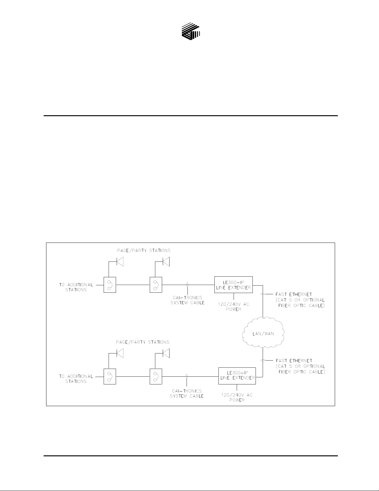
The GAI-Tronics Model LE300-IP Line Extenders are used in pairs to connect two Page/Party®,
SmartSeries or ICS Page/Party
Ethernet access. Refer to Figure 1 for a typical block diagram.
®
cable segments over an IP Network using Fast Ethernet or Gigabit
Figure 1. Typical System Block Diagram
GAI-Tronics Corporation 400 E. Wyomissing Ave. Mohnton, PA 19540 USA
610-777-1374 800-492-1212 Fax: 610-796-5954
V
ISIT WWW.GAI-TRONICS.COM FOR PRODUCT LITERATURE AND MANUALS
Page 5

Pub. 42004-488C
ODEL LE300-IP PAGE/PARTY® LINE EXTENDER PAGE 2 of 68
M
Model LE300-IP Line Extender and Sub-Component Details
Refer to Figure 2 below for dimensional information and the sub-component layout of the Model LE300IP Line Extender.
Figure 2. Model LE300-IP Line Extender Outline
e:\standard ioms - current release\42004 i nstr. manuals\4 2004-488c.doc
09/14
Page 6
Pub. 42004-488C
ODEL LE300-IP PAGE/PARTY® LINE EXTENDER PAGE 3 of 68
M
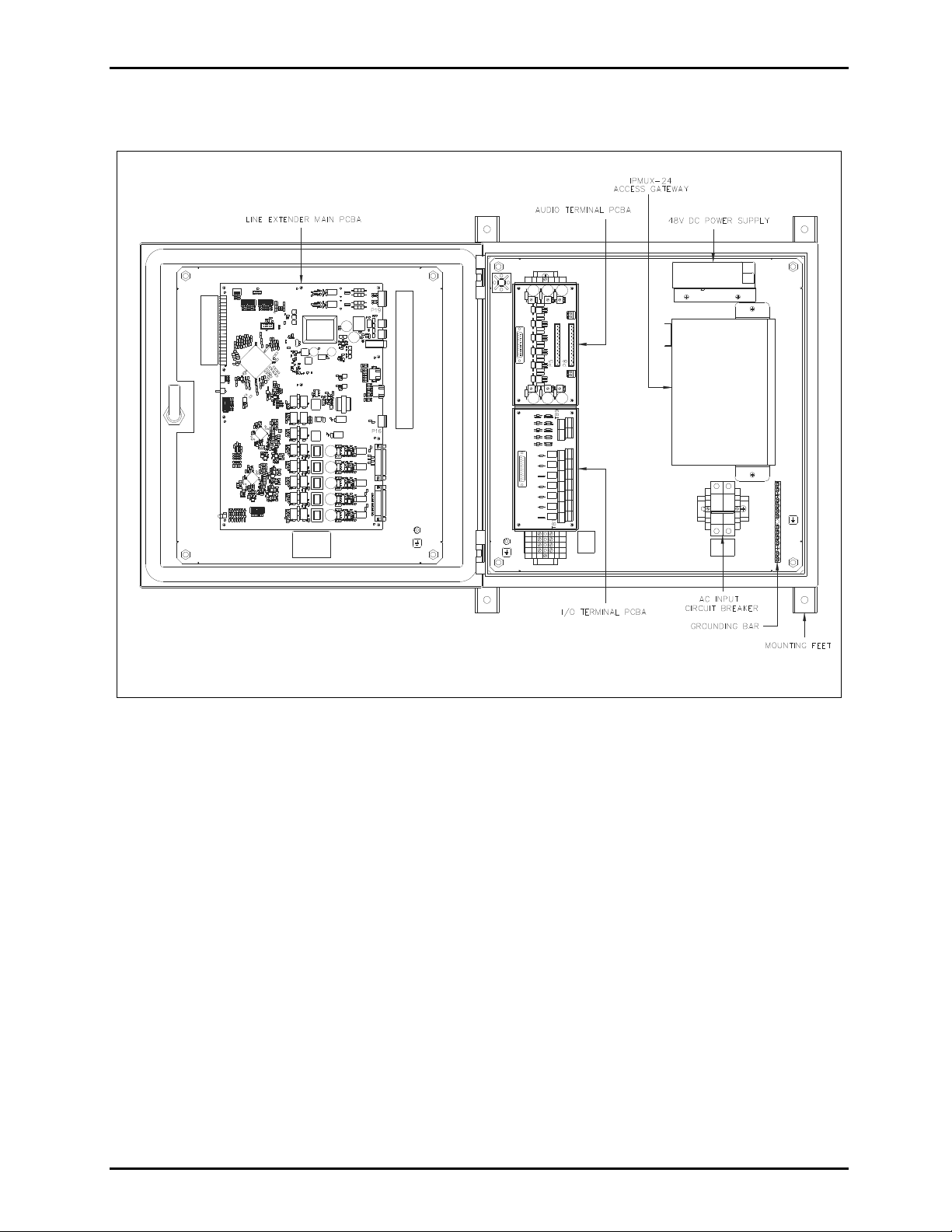
Model LE300-IP Internal View
Figure 3. Interior View of Components - Model LE300-IP
e:\standard ioms - current release\42004 i nstr. manuals\4 2004-488c.doc
09/14
Page 7
Pub. 42004-488C
ODEL LE300-IP PAGE/PARTY® LINE EXTENDER PAGE 4 of 68
M
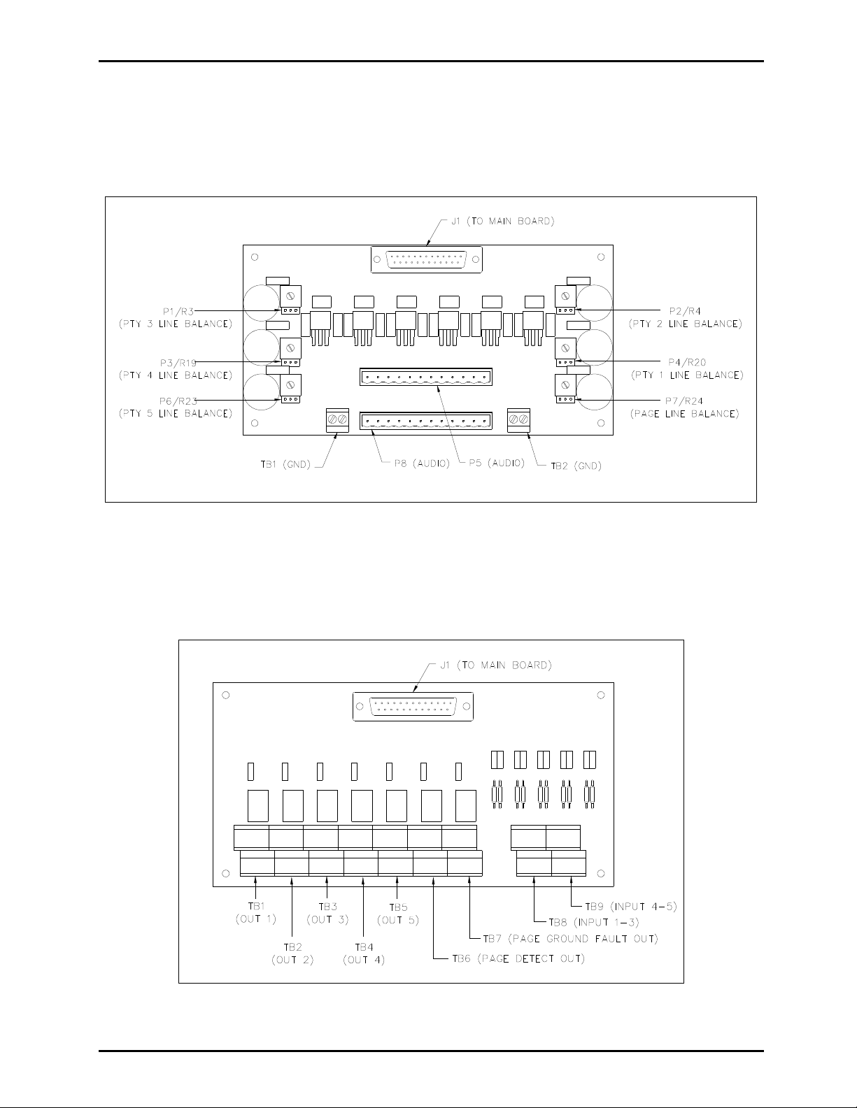
Audio Termination Connection Module
The page line and party line 1–5 conductors of the Page/Party® system cable connect to the Audio
Termination Connection Module. This module also can provide the 33-ohm line balance resistance needed
for the audio lines. Audio line functions are described later in this manual.
Figure 4. Audio Termination Connection Module
Input/Output (I/O) Termination Connection Module
The I/O Termination Connection Module connects the control wiring needed to send contact closures
across the line extenders. I/O features and functions are described later in this manual.
Figure 5. Input/ Output (I/O) Connection Module
e:\standard ioms - current release\42004 i nstr. manuals\4 2004-488c.doc
09/14
Page 8
Pub. 42004-488C
ODEL LE300-IP PAGE/PARTY® LINE EXTENDER PAGE 5 of 68
M
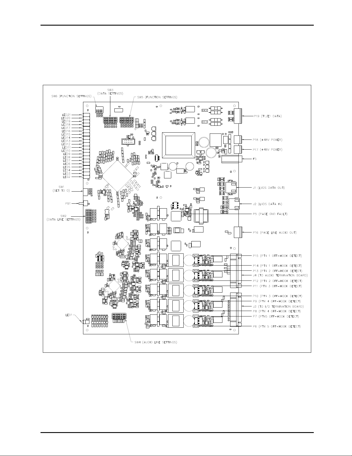
Main PCBA
The Main PCBA contains all the central processing and line driver circuitry for the Model LE300-IP Line
Extender. The board contains numerous connectors, switches and jumpers for setting the line extender
operating parameters. Figure 6 below identifies the various components on the Main PCBA. Features and
functions of each are described later in this manual.
Figure 6. Main PCBA
e:\standard ioms - current release\42004 i nstr. manuals\4 2004-488c.doc
09/14
Page 9

Pub. 42004-488C
ODEL LE300-IP PAGE/PARTY® LINE EXTENDER PAGE 6 of 68
M
Fea tures and Functions
The Model LE300-IP Page/Party® Line Extender provides the following features between Page/Party®
system cables.
Page Line Audio Transmission
A pair of Model LE300-IP Line Extenders provides page line audio transmission between two Page/Party®
system cables. This transmission is half-duplex operation.
When the line extender detects a peak audio level equal or above a Peak Voltage Level Detection
Threshold, it immediately switches audio “on” in that direction for the Transmission Direction Hold Time.
Audio from the other direction is muted and ignored during that time. Audio is not switched “off” until it
is continuously below the Peak Voltage Level Detection Threshold for the Transmission Direction Hold
Time. The DIP switch SW2 positions 5–7, located on the Main PCBA, selects Peak Voltage Level
Detection Threshold and Transmission Direction Hold Time. Refer to Figure 6 for the location of Switch
SW2 on the Main PCBA and Table 1 and Table 2 below for setting options.
Table 1. Transmission Direction Hold Time Settings on Main PCBA
SW2-5 SW2-6 Transmission Direction Hold Time
Open* Open * 1280 milliseconds
Closed Open 640 milliseconds
Open Closed 160 milliseconds
Closed Closed 40 milliseconds
NOTES: 1. Changes to this parameter take effect without cycling power.
2. *Indicates default position.
Table 2. Peak Voltage Level Detection Threshold on Main PCBA
SW2-7 Peak Voltage Level Detection Threshold
Open* −12 dB relative to nominal
Closed −24 dB relative to nominal
NOTES: 1. Changes to this parameter take effect without cycling power.
2. *Indicates default position.
e:\standard ioms - current release\42004 i nstr. manuals\4 2004-488c.doc
09/14
Page 10

Pub. 42004-488C
ODEL LE300-IP PAGE/PARTY® LINE EXTENDER PAGE 7 of 68
M
Page Line Audio Monitoring Output
The Model LE300-IP Line Extender provides a balanced 600-ohm audio output for monitoring audio on
both the local and remote page lines. The LE300-IP mixes the local and remote page line audio and routes
it to the 600-ohm audio output terminals. This audio can be sent to any external audio device (recorder,
radio transmitter, amplifier, etc.) with an input impedance equal to or greater than 600 ohms. The audio
output gain is adjustable using DIP switch SW3 positions 5–8 on the Main PCBA. Refer to Figure 6 for
the location of Switch SW3 on the Main PCBA and the tables below for setting options.
Table 3. Page Line Monitor Output Gain Setting on Main PCBA
SW3-5
SW3-6
SW3-7
SW3-8
Monitor Output
Gain
Open* Open* Open* Open* 0 dB
Closed Open Open Open −30 dB
Open Closed Open Open −27 dB
Closed Closed Open Open −24 dB
Open Open Closed Open −21 dB
Closed Open Closed Open −18 dB
Open Closed Closed Open −15 dB
Closed Closed Closed Open −12 dB
Open Open Open Closed −9 dB
Closed Open Open Closed −6 dB
Open Closed Open Closed −3 dB
Closed Closed Open Closed 0 dB
Open Open Closed Closed +3 dB
Closed Open Closed Closed +6 dB
Open Closed Closed Closed +9 dB
Closed Closed Closed Closed +12 dB
NOTES: 1. Changes to this parameter take effect without cycling power.
2. *Indicates default position.
e:\standard ioms - current release\42004 i nstr. manuals\4 2004-488c.doc
09/14
Page 11

Pub. 42004-488C
ODEL LE300-IP PAGE/PARTY® LINE EXTENDER PAGE 8 of 68
M
Page Line Audio Detect Output Contact
The Model LE300-IP Line Extender provides a contact closure output that activates whenever audio is
detected on the page line. The contact can be set to close when audio is detected at the local page line, the
remote page line, or both. Typically this contact is used in conjunction with the Page Line Audio
Monitoring Output to provide a control contact to external devices or systems when page line audio is
present. The contact remains active for 1 second after the audio is no longer detected. DIP switch SW5
positions 6 and 7 enables or disables the output contact. Refer to Figure 6 for the location of switch SW5
on the Main PCBA and the tables below for setting options.
Table 4. Page Line Audio Detect Contact Main PCBA
SW5-6 SW5-7 Audio Detect Contact Operati on
Closed Closed Disabled
Open Closed Local page line audio activates the contact
Closed Open Remote page line audio activates the contact
Open* Open* Both Local and Remote page line audio activates the contact
NOTES: 1. Changes to this parameter take effect without cycling power.
2. *Indicates default position.
Page Line FSK Data Transmission (SmartSeries System s)
A pair of Model LE300-IP Line Extenders re-generates the FSK data transmission between two
SmartSeries Page/Party
SmartSeries Page/Party
operation, both line extenders must have this feature enabled by setting DIP switch SW5 position 1. Refer
to Figure 6 for the location of switch SW5 on the Main PCBA and Table 5 below for setting options.
SW5-1 Page Line FSK Transmission
Open* FSK data is disabled.
Closed FSK data is enabled.
NOTES: 1. Changes to this parameter take effect without cycling power.
2. *Indicates default position.
OTE: FSK operation and VLC operation (described below) cannot be enabled at the same time.
N
FSK operation is only used with SmartSeries systems.
®
system cables. FSK data transmission occurs on the page line allowing
®
stations to communicate with the ADVANCE system control cabinet. For proper
Table 5. Page Line FSK Transmission on Main PCBA
VLC operation is only used within NON-SmartSeries systems. If both 50 kHz VLC and FSK are
enabled at the same time, neither feature will function correct ly.
e:\standard ioms - current release\42004 i nstr. manuals\4 2004-488c.doc
09/14
Page 12
Pub. 42004-488C
ODEL LE300-IP PAGE/PARTY® LINE EXTENDER PAGE 9 of 68
M
Page Line 50 kHz VLC Transmission
A pair of Model LE300-IP Line Extenders re-generates the 50 kHz VLC control signal between two
Page/Party
and is typically used to alter the speaker volume of Page/Party
signals may also be used for other on/off control functions on some Page/Party
®
system cables. The 50 kHz VLC (Volume Level Control) signaling occurs on the page line
®
stations equipped VLC receivers. VLC
®
systems. For proper
operation, both line extenders must have this feature enabled by setting DIP switch SW5 position 2. Refer
to Figure 6 for the location of switch SW5 on the Main PCBA and Table 6 below for setting options.
Table 6. Page Line 50 kHz VLC Transmission Setting on Main PCBA
SW5-2 Page Line 50 kHz VLC Transmission
Open* 50 kHz VLC is disabled.
Closed 50 kHz VLC is enabled.
NOTES: 1. Changes to this parameter take effect without cycling power.
2. *Indicates default position.
OTE: FSK operation and VLC operation (described above) cannot be enabled at the same time.
N
FSK operation is only used with SmartSeries systems.
VLC operation is only used within NON-SmartSeries systems. If both 50 kHz VLC and FSK are
enabled at the same time, neither feature will function correct ly.
Page Line Ground Fault Detection
The Model LE300-IP Line Extenders provide page line ground fault detection on the local Page/Party®
system cable. If multiple line extenders are connected to the same Page/Party
one page line ground fault detector may be enabled. A shorting clip setting at header P5 on the Main
PCBA enables the page line ground fault detection. Refer to Figure 6 for the location of header P5 on the
Main PCBA and Table 7 below for setting options:
Table 7. Page Line Ground Fault Detection Setting on Main PCBA
P5 Shorting Clip Page Line Ground Fault Detection
Pins 1–2* Page line ground fault detection is disabled.
Pins 2–3 Page line ground fault detection is enabled.
Removed Page line ground fault detection is disabled.
NOTES:
1. If connecting an LE300-IP Line Extender to the same system cable segment as an ADVANCE
Page/Party
®
Interface (PPI) card, disable the LE300-IP page line ground fault detector. The PPI card
contains the ground fault detector. If both ground fault circuits are enabled simultaneously,
intermittent SmartSeries FSK data errors will occur between the PPI card and SmartSeries stations.
2. Changes to this parameter take effect without cycling power.
3. *Indicates default position.
®
system cable segment, only
e:\standard ioms - current release\42004 i nstr. manuals\4 2004-488c.doc
09/14
Page 13

Pub. 42004-488C
ODEL LE300-IP PAGE/PARTY® LINE EXTENDER PAGE 10 of 68
M
Page Line Ground Fault Re-generation
When a ground fault is detected at a remote LE300-IP Line Extender, the ground fault can be duplicated
on the local Page/Party
®
system cable. DIP switch SW5 position 3 enables regeneration of the ground
fault. Refer to Figure 6 for the location of switch SW5 on the Main PCBA and Table 8 below for setting
options.
Table 8. Page Line Ground Fault Regeneration Setting on Main PCBA
SW5-3 Page Line Groun d Fault Regeneration
Open* Disabled - Page line ground faults detected on the remote system cable are NOT
regenerated on the local system cable.
Closed Enabled - Page line ground faults detected on the remote system cable are regenerated on
the local system cable.
NOTES:
1. The ground fault regeneration feature is used in SmartSeries systems to allow a ground fault on the
remote cable segment to be detected by the system control cabinet. Disable this feature if the line
extender is not installed in this type system.
2. Changes to this parameter take effect without cycling power.
3. *Indicates default position.
Page Line Ground Fault Output Contact
The Model LE300-IP provides a relay contact that activates whenever a ground fault is detected on the
local page line, remote page line or both the page lines. The ground fault detection feature (described
above) must be enabled. The contact output can be used to activate an external device or system that
annunciates the fault condition. The DIP switch SW5 positions 4 and 5 configure which page line ground
faults activate this contact. Refer to Figure 6 for the location of switch SW5 on the Main PCBA and Table
9 below for setting options.
Table 9. Page Line Ground Fault Contact Setting on Main PCBA
SW5-4 SW5-5 Page Line Ground Fault Contact
Closed Closed Disabled
Closed Open Remote page line ground fault activates the contact.
Open Closed Local page line ground fault activates the contact.
Open* Open* Both Local and Remote page line ground faults activate the contact.
NOTES: 1. Changes to this parameter take effect without cycling power.
2. *Indicates default position.
e:\standard ioms - current release\42004 i nstr. manuals\4 2004-488c.doc
09/14
Page 14

Pub. 42004-488C
ODEL LE300-IP PAGE/PARTY® LINE EXTENDER PAGE 11 of 68
M
Party Line Audio Transmission
A pair of Model LE300-IP Line Extenders provides full duplex party line audio between two Page/Party®
system cables, for party lines 1 through 5. During on-hook conditions of the party lines (meaning no
handset stations are in use), the LE300-IP will mute the local party line analog circuits.
If it is necessary to have party line audio enabled even when no stations are off-hook, DIP switch SW6-3
may be closed to disable this muting feature. This switch affects the on-hook muting function of all five
party lines simultaneously.
Refer to Figure 6 for the location of switch SW6 on the Main PCBA and Table 10 below for setting
options.
Table 10. Party Line On-Hook Muting Setting on Main PCBA
SW6-3 Party Line On-H ook Muting
Open* Enabled – local party lines are muted when no handset stations are in use.
Closed Disabled – party line audio is never muted.
NOTES: 1. Changes to this parameter take effect without cycling power.
2. *Indicates default position.
e:\standard ioms - current release\42004 i nstr. manuals\4 2004-488c.doc
09/14
Page 15

Pub. 42004-488C
ODEL LE300-IP PAGE/PARTY® LINE EXTENDER PAGE 12 of 68
M
Party Line Off-Hook Detection
The Model LE300-IP Line Extenders provide off-hook detection on the local Page/Party® system cable for
party lines 1 through 5. An off-hook condition means a handset station is in use. If multiple line extenders
are connected to the same Page/Party
®
system cable segment, only one off-hook detector can be enabled.
If connecting an LE300-IP to the same system cable segment as an ADVANCE Page/Party
®
Interface
(PPI) card, disable the LE300-IP off-hook detection for party lines 1 and 2. The PPI card contains offhook detection for party lines 1 and 2.
Several shorting clips (P6–P15) are used to enable the off-hook detection feature on party line 1 through 5.
Two shorting clips are associated with each party line and must be set to the same position for proper
operation. The party lines 1 through 5 are configured independently. Refer to Figure 6 for the location of
P6–P15 on the Main PCBA and Table 11 below for setting options.
Table 11. Party Line Off-Hook Detection Setting on Main PCBA
Party Line Headers Shorting Clip Off-Hook Dete ction
Pins 1–2* Disabled
Party Line 1 P15, P14
Pins 2–3 Enabled
Removed Disabled
Pins 1–2* Disabled
Party Line 2 P13, P12
Pins 2–3 Enabled
Removed Disabled
Pins 1–2* Disabled
Party Line 3 P11, P10
Pins 2–3 Enabled
Removed Disabled
Pins 1–2* Disabled
Party Line 4 P9, P8
Pins 2–3 Enabled
Removed Disabled
Pins 1–2* Disabled
Party Line 5 P7, P6
Pins 2–3 Enabled
Removed Disabled
NOTES:
1. Changes to this parameter take effect without cycling power.
2. *Indicates default position.
e:\standard ioms - current release\42004 i nstr. manuals\4 2004-488c.doc
09/14
Page 16

Pub. 42004-488C
ODEL LE300-IP PAGE/PARTY® LINE EXTENDER PAGE 13 of 68
M
Party Line Off-Hook Regeneration
When an off-hook handset station is detected, the LE300-IP can transmit the off-hook condition to remote
line extenders so that it is duplicated on the remote Page/Party
®
system cable. Typically this feature is
used in systems that contain a telephone interface device so that the caller is transferred to the party line
when a handset station answers the call. DIP switch SW6 position 2 is used to enable this feature. This
switch affects the off-hook regeneration function of all five party lines. Refer to Figure 6 for the location
SW6 on the Main PCBA and Table 12 below for setting options.
Table 12. Off-Hook Regeneration on Main PCBA
SW6-2 Off-Hook Regeneration Setting
Open* Enabled – an off hook condition on the local party line is regenerated at the
remote line extender.
Closed Disabled
NOTES: 1. Changes to this parameter take effect without cycling power.
2. *Indicates default position.
Audio Line Muting
In some line extender configurations using the LVDS data link, the Page/Party® system cable is not
connected to the line extender. In this case, all audio lines (page and party lines 1 through 5) should be
muted since they are not physically connected. DIP switch SW6 position 4 on the Main PCBA enables
this feature. If this feature is enabled, it is unnecessary to disconnect the audio lines using the audio line
relays (mentioned above). Refer to Figure 6 for the location of SW6 on the Main PCBA and Table 13
below for setting options.
Table 13. Audio Line Mute Setting on Main PCBA
SW6-4 Mute Analog Lines Setting
Open* Disabled - Party lines 1–5 and page line are operational.
Closed Enabled - Party lines 1–5 and page line are muted.
NOTES: 1. Changes to this parameter take effect without cycling power.
2. *Indicates default position.
e:\standard ioms - current release\42004 i nstr. manuals\4 2004-488c.doc
09/14
Page 17

Pub. 42004-488C
ODEL LE300-IP PAGE/PARTY® LINE EXTENDER PAGE 14 of 68
M
Audio Line Connection Relays
The Model LE300-IP has relays that disconnect the page, party lines 1 through 5 and the page monitoring
audio output connections from the Main PCBA. The disconnect feature is used for special applications
such as connection of a single party line system, or other scenarios in which a particular audio line is not
physically connected to the line extender. DIP switch SW4 is used to control the audio line disconnect
feature. Refer to Figure 6 for the location of SW4 on the Main PCBA and Table 14 below for setting
options.
Table 14. Audio Line Connection Relay Settings on Main PCBA
Audio Line Switch SW4 Setting Field Wiring
Party Line 5 SW4-1
Party Line 4 SW4-2
Party Line 3 SW4-3
Party Line 2 SW4-4
Party Line 1 SW4-5
Page Line SW4-6
Page Monitor SW4-7
N/A SW4-8
Open Disconnected
Closed* Connected
Open Disconnected
Closed* Connected
Open Disconnected
Closed* Connected
Open Disconnected
Closed* Connected
Open Disconnected
Closed* Connected
Open Disconnected
Closed* Connected
Open Disconnected
Closed* Connected
Open
Not used.
Closed*
NOTES: 1. Changes to this parameter take effect without cycling power.
2. *Indicates default position.
e:\standard ioms - current release\42004 i nstr. manuals\4 2004-488c.doc
09/14
Page 18

Pub. 42004-488C
ODEL LE300-IP PAGE/PARTY® LINE EXTENDER PAGE 15 of 68
M
Page/Party® Line Balance
For proper system operation, the page line and party lines 1 through 5 must be terminated with a resistance
of approximately 33 ohms. The Model LE300-IP provides potentiometers to set the line balance resistance
on the page line and five party lines. The line balance resistors are located on the Audio Termination
Connection Module next to the page and party line terminal blocks. The line balance resistors are
adjustable or can be disabled using shorting clips P1–P7.
If connecting an LE300-IP Line Extender to the same system cable segment as an ADVANCE Page/Party
Interface (PPI) card, disable the line balance for party lines 1, 2, and the page line. The PPI card provides
the line balance resistors for these audio lines. Refer to Figure 3 for the location of the Audio Termination
Connection Module. Refer to Figure 4 for the location of the jumpers and potentiometers on the Audio
Termination Connection Module and Table 15 below for setting details.
Table 15. Page/Party
Audio Line Header Shorting Clip Line Balance Adjustment
®
Line Balance Settings on Audio Termination Connection Module
Potentiometer
Pins 1–2* Disabled
®
Party Line 5 P6
Party Line 4 P3
Party Line 3 P1
Party Line 2 P2
Party Line 1 P4
R23 Pins 2–3 Enabled
Removed Disabled
Pins 1–2* Disabled
R19 Pins 2–3 Enabled
Removed Disabled
Pins 1–2* Disabled
R3 Pins 2–3 Enabled
Removed Disabled
Pins 1–2* Disabled
R4 Pins 2–3 Enabled
Removed Disabled
Pins 1–2* Disabled
R20 Pins 2–3 Enabled
Removed Disabled
Pins 1–2* Disabled
Page Line P7
Removed Disabled
NOTES: *Indicates default position.
e:\standard ioms - current release\42004 i nstr. manuals\4 2004-488c.doc
09/14
R24 Pins 2–3 Enabled
Page 19

Pub. 42004-488C
ODEL LE300-IP PAGE/PARTY® LINE EXTENDER PAGE 16 of 68
M
Contact Closure Inputs & Relay Outputs (I/O)
Five independent contact closures can be transmitted across a pair of line extenders, meaning that an active
input contact on the local line extender results in the corresponding output relay contact energizing on the
remote line extender. Contact closures are bi-directional between line extender pairs.
Example: Closing a switch contact across input #1 of the local line extender results in relay output #1
activating on the remote line extender and vice versa. When the input contact is removed the
corresponding output relay de-activates. No switch or jumper setting is required on the Main PCBA for
configuring the I/O feature.
OTE: Any active output contacts will deactivate if the data link is broken between the line extenders.
N
Echo Cancellation
Line echo (also known as electric or hybrid echo) is created by the electrical circuitry connected to a twowire (full duplex) audio system. Echo is inherent in all full-duplex audio systems and is affected by the
audio line length and line impedance mismatches. The presence of audible echoes results in undesirable
audio quality. This kind of quality degradation is inherent in network equipment and end-user telephone
devices.
To minimize echo, the Model LE300-IP performs an echo cancellation sequence on party lines 1 through
5. The echo cancellation process takes approximately 15 seconds and is performed automatically one
minute after power is applied to the LE300-IP. This delay allows all power levels to stabilize prior to
performing echo cancellation.
OTE: Signal impulses are transmitted onto the party lines during the echo cancellation process. Handset
N
station users on a party line will hear the signals in the handset receiver. For troubleshooting purposes, the
1-minute delay may be disabled by closing DIP switch SW6 position 1. Refer to Figure 6 for the location
of SW6 on the Main PCBA and Table 16 below for setting details.
Table 16. Echo Cancellation Power-On Delay Setting on Main PCBA
SW6-1 Echo Cancellation Power-On Delay
Open* 1 minute
Closed No delay
NOTES: 1. Changes to this parameter take effect when cycling power.
2. *Indicates default position.
Manual Initiation of Echo Canceling
Echo cancellation can be manually initiated as described below.
Press and release push button PB1 on the Main PCBA three times. The push button must be pressed for at
least 0.25 second and no more than 2 seconds each time. The timing requirement is meant to prevent
accidental requests. If an error is made with the push-button timing, the sequence must be repeated from
the beginning.
The LEDs on the Main PCBA will indicate the progress of the echo canceling sequence. One column of
LEDs turns on after each push button and press release until the sequence is started. Once the sequence is
started, those LEDs remain on, and a countdown timer is displayed on the remaining LEDs. The LEDs
turn OFF after the echo cancellation training sequence is complete.
e:\standard ioms - current release\42004 i nstr. manuals\4 2004-488c.doc
09/14
Page 20

Pub. 42004-488C
ODEL LE300-IP PAGE/PARTY® LINE EXTENDER PAGE 17 of 68
M
Data Links between Line Extenders
The Model LE300-IP Line Extender is equipped with two different data link types for connecting to
another line extender. The two data link types are a T1/E1 link via the IP network and a Low Voltage
Differential Signaling (LVDS) link. The type of data link(s) used is determined by the system architecture.
It is possible to use both types at the same time to achieve complex system architectures. The data link
type, their intended use, and the applicable switch settings are described below.
T1/E1 over an Ethernet IP Network
This data link is used to connect two Model LE300-IP Line Extenders using an IP Network. The Model
LE300-IP contains an IPmux-24, which converts the data stream from its E1/T1 port into packets for
transmission over the network. These packets are transmitted via the Ethernet network port to a remote
LE300-IP device that receives the packets and converts them back to their original T1/E1 format.
The LE300-IP Line Extender should be connected to the closest Ethernet switch in the network. The
distance between LE300-IP Line Extender and the Ethernet switch determines the type of cable connection
needed. CAT5 or CAT6 cable can be used if the distance is <100 meters. The CAT5 or CAT6 cable
should be terminated with RJ-45 plugs for connection to the LE300-IP Line Extender and the Ethernet
switch.
For distances exceeding 100 meters, fiber optic cable must be used. When using fiber optic cable, a small
form-factor pluggable (SFP) module must be purchased separately and plugged into the IPmux-24 to
provide a termination point for the fiber cable inside the line extender. The optional SFP modules are
available for use with multi-mode fiber optic or single mode fiber optic cable. The SFP modules contain
LC-type fiber optic connector. Refer to the SFP data sheets for maximum cable distances.
Low Voltage Differential Signaling (LVD S) Data Link
The LVDS data link connection is used to connect two or more Model LE300-IP Line Extenders in a
“daisy chain” fashion when the line extenders are located within 10 meters of each other. The LVDS data
link requires a straight-through CAT5e cable between line extenders. Each line extender contains an
LVDS data “in” port and an LVDS data “out” port. The “out” port of the first line extender connects to the
“in” port of the next line extender. This connection scheme can be used to link up to a maximum of eight
line extenders and is typically used when multiple line extenders are installed in a central location.
e:\standard ioms - current release\42004 i nstr. manuals\4 2004-488c.doc
09/14
Page 21

Pub. 42004-488C
ODEL LE300-IP PAGE/PARTY® LINE EXTENDER PAGE 18 of 68
M
Configuring the Data Links
The T1/E1 and LVDS data link parameters between line extenders must be configured using multiple DIP
switch settings on the Main PCBA. The following sections describe each parameter and the switch
settings.
T1/E1 Data Format Selection
The LE300-IP supports both T1 and E1 data line connections between units. T1 is a digital circuit that
uses the DS-1 (Digital Signaling level 1) signaling format to transmit voice/data at 1.544 Mbps. T1 can
carry up to 24 digital channels for voice or data. E1 is the European equivalent which carries information
at the rate of 2.048 Mbps. E1 is used to transmit 30 digital channels for voice or data plus one channel for
signaling, and one channel for framing and maintenance.
In the case of LE300-IP, it is always be set to T1 (default setting). DIP switch SW5 position 8 on the Main
PCBA selects the data link format for the digital audio transmission between line extenders. Both line
extenders must be set to the same format. Refer to Figure 6 for the location of SW5 on the Main PCBA
and Table 17 below for setting details.
Table 17. Data Format Setting on Main PCBA
SW5-8 Format
Open* T1 Mode (1.544 Mbps, 24-channel)
Closed E1 Mode (2.048 Mbps, 32-channel)
NOTES: 1. Changes to this parameter take effect after cycling power.
2. *Indicates default position.
T1 Line Build-out Settings
This option allows the user to control the wave shape being output by the transmitter. This helps to correct
problems related to long copper cables. Improperly setting this switch will cause signal degradation. The
proper setting refers to the cable distance between two LE300-IP Line Extenders. In the case of LE300-IP
Line Extenders it should always be set to 0–133 feet (default setting). DIP switches SW2 positions 1–3 on
the Main PCBA selects line-build out parameters. Refer to Figure 6 for the location of SW2 on the Main
PCBA and Table 18 below for setting details.
Table 18. T1 Line Length Setting on Main PCBA
SW2-1 SW2-2 SW2-3 T1 Line Length
Open (up)* Open (up)* Open (up)* 0 to 133 feet
Closed (down) Open (up) Open (up) 133 to 266 feet
Open (up) Closed (down) Open (up) 266 to 399 feet
Closed (down) Closed (down) Open (up) 399 to 533 feet
Open (up) Open (up) Closed (down) 533 to 655 feet
NOTES: 1. Changes to this parameter take effect without cycling power.
2. *Indicates default position.
3. These switches have no effect in E1 mode.
e:\standard ioms - current release\42004 i nstr. manuals\4 2004-488c.doc
09/14
Page 22

Pub. 42004-488C
ODEL LE300-IP PAGE/PARTY® LINE EXTENDER PAGE 19 of 68
M
T1/E1 Receiver Equalization Gain Limit
This option allows the user to compensate for diminishing signal intensity over the data line by adjusting
the sensitivity of the receiver. By setting the Receive Equalizer Gain Limit, very long copper lines can be
utilized. DIP switch SW2 position 4 on the Main PCBA selects the parameter. Refer to Figure 6 for the
location of SW2 on the Main PCBA and Table 19 below for setting details.
Table 19. Receive Equalizer Gain Limit Setting on Main PCBA
SW2-4
Receive Equalization Gain Limit
T1 Mode E1 Mode
Open (up)* −36 dB (long haul) −12 dB (short haul)
Closed (down) −15 dB (limited long haul) −43 dB (long haul)
NOTES: 1. Changes to this parameter take effect without cycling power.
2. *Indicates default position.
T1/E1 Clock Source
In case of the LE300-IP, both Line Extenders should be set as the master clock source for proper operation
with the IPmux-24. The slave unit receives the clock from the master. DIP switch SW3 positions 1 and 2
on the Main PCBA select T1/E1 clock parameters. Refer to Figure 6 for the location of SW3 on the Main
PCBA and Table 20 below for setting details.
Table 20. Master Clock setting on Main PCBA
SW3-1 SW3-2 Clock Source
Open* Open* LE300-IP is the T1/E1 Master (generates the T1/E1 clock).
Closed Closed LE300-IP is the T1/E1 Slave (receives the T1/E1 clock from master).
NOTES: 1. Changes to this parameter take effect after cycling power.
2. *Indicates default position.
e:\standard ioms - current release\42004 i nstr. manuals\4 2004-488c.doc
09/14
Page 23

Pub. 42004-488C
ODEL LE300-IP PAGE/PARTY® LINE EXTENDER PAGE 20 of 68
M
T1/E1 Data Line Grounding
T1/E1 data line can be floating or grounded. When floating, neither conductor of the data line cable pair is
connected to ground. Headers P20 and P21 control the grounding of the T1/E1 lines. Grounding the
T1/E1 lines may reduce emissions if it becomes an installation concern. Refer to Figure 6 for the location
of P20 and P21 on the Main PCBA and Table 21 below for setting details.
Table 21. T1/E1 Data Line Grounding setting on Main PCBA
Header Shorting Clip Grounding Condit ion
P20 1–2* T1/E1 Rx line floating
2–3 T1/E1 Rx line grounded
Removed T1/E1 Rx line floating
P21 1–2* T1/E1 Tx line floating
2–3 T1/E1 Tx line grounded
Removed T1/E1 Tx line floating
*Indicates default position.
NOTE
LVDS Data Link Settings
Do not ground the T1/E1 lines at both ends. Doing so will create a ground loop.
The LVDS “in” port is disabled unless it is receiving a signal from LVDS “out” from another line
extender. Switch SW3 position 3 enables the LVDS “in” port. Refer to Figure 6 for the location of SW3
on the Main PCBA and Table 22 below for setting details.
Table 22. LVDS “IN” Setting on Main PCBA
SW3-3 Enable/Disable LVDS “IN” Port
Open* The LVDS “in” port is disabled (no cable connection from another LE300-IP.)
Closed The LVDS “in” port is enabled (cable is connected to LVDS “out” cable connection
from anther to LVDS.
NOTES: 1. Changes to this parameter take effect after cycling power.
2. *Indicates default position.
e:\standard ioms - current release\42004 i nstr. manuals\4 2004-488c.doc
09/14
Page 24

Pub. 42004-488C
ODEL LE300-IP PAGE/PARTY® LINE EXTENDER PAGE 21 of 68
M
The LVDS “out” port is disabled unless the line extender is transmitting an LVDS signal to another line
extender’s LVDS “in” port. Switch SW3 position 4 enables the LVDS “out” port. Refer to Figure 6 for
the location of SW3 on the Main PCBA and Table 23 below for setting details.
Table 23. LVDS “OUT” Setting on Main PCBA
SW3-4 Enable/Disable LVDS “OUT” Port
Open* LVDS “out” is disabled.
Closed LVDS “out” is enabled.
NOTES: 1. Changes to this parameter take effect without cycling power.
2. *Indicates default position.
NOTE
Do not connect LVDS “in” to LVDS “out” on the same LE300-IP Line Extender.
Doing so creates a feedback path that usually results in (extremely loud) oscillations on the page line, all
party lines, and possibly the contact outputs.
LVDS Port Indicators
Each LVDS port has two LEDs. The green LED is ON when the LE300-IP detects a signal connection
from the other LE300-IPs connected to that port. The yellow/orange LED is ON when the LE300-IP
detects page line data (SmartSeries FSK or 50 kHz VLC) on the LVDS port.
e:\standard ioms - current release\42004 i nstr. manuals\4 2004-488c.doc
09/14
Page 25

Pub. 42004-488C
ODEL LE300-IP PAGE/PARTY® LINE EXTENDER PAGE 22 of 68
M
Typical Data Link Settings
The following section shows the most common line extender connection schemes and the expected T1/E1
and LVDS data line parameters for each. Consult the applicable tables to determine the correct switch
settings. Consult GAI-Tronics for technical support of connection schemes not shown in this manual.
Point-to-Point Page/Party® System Connection
Figure 7. Point-to-Point Page/Party
®
System Connection
Table 24. Point-to-Point Page/Party
Parameter Switch Configuration Description
T1/E1 Clock
Source
LVDS Clock
Source
SW3-1
SW3-2
SW3-3
SW3-4
Unit A & B is the master clock sources:
SW3-1 (open) SW3-2 (open)
Not used - disable both LVDS “in” and “LVDS out”:
SW3-3 (open) SW3-4 (open)
®
System Connection Table
e:\standard ioms - current release\42004 i nstr. manuals\4 2004-488c.doc
09/14
Page 26

Pub. 42004-488C
ODEL LE300-IP PAGE/PARTY® LINE EXTENDER PAGE 23 of 68
M
Point to Multi-point Page/Party® System Connection
Figure 8. Point to Multi-point Page/Party
®
System Connection
Table 25. Point to Multi-point Page/Party
Parameter Switch Configuration Description
T1/E1 Clock
Source
LVDS Data
Line
SW3-1
SW3-2
SW3-3
SW3-4
Units A, B, C, D, E, & F are the master T1/E1 clock sources:
SW3-1 (open) SW3-2 (open)
LVDS data link is used between units A, B and C.
Unit A - “LVDS in” disabled, “LVDS out” enabled:
®
System Connection Table
SW3-3 (open) SW3-4 (closed)
Unit B - “LVDS in” enabled, “LVDS out” enabled:
SW3-3 (closed) SW3-4 (closed)
Unit C - “LVDS in ” enabled, “LVDS out” disabled:
SW3-3 (closed) SW3-4 (open)
Mute Analog
Lines
SW6-4 Units B and C have the page and party lines muted since there is not a
Page/Party
®
cable connected:
SW6-4 (closed)
e:\standard ioms - current release\42004 i nstr. manuals\4 2004-488c.doc
09/14
Page 27

Pub. 42004-488C
ODEL LE300-IP PAGE/PARTY® LINE EXTENDER PAGE 24 of 68
M
Series Connection of Page/Party® System
Figure 9. Series Connection of Page/Party
®
System
®
Table 26. Series Connection of Page/Party
System Table
Parameter Switch Configuration Description
T1/E1 Clock
Source
LVDS Clock
Source
SW3-1
SW3-2
SW3-3
SW3-4
Units A, B, C, & D are the master T1/E1 clock sources:
SW3-1 (open) SW3-2 (open)
LVDS clock is used between units B and C:
Unit B - “in” disabled, “out” enabled:
SW3-3 (open) SW3-4 (closed)
Unit C - “in” enabled, “out” disabled:
SW3-3 (closed) SW3-4 (open)
Mute Analog
Lines
SW6-4 Unit C has the page and party lines muted since there is not a Page/Party®
cable connected:
SW6-4 (closed)
e:\standard ioms - current release\42004 i nstr. manuals\4 2004-488c.doc
09/14
Page 28

Pub. 42004-488C
ODEL LE300-IP PAGE/PARTY® LINE EXTENDER PAGE 25 of 68
M
IP Bandwidth Requirements
Each pair of LE300-IP Line Extenders requires approximately 3 Mb of bandwidth on the network. Actual
bandwidth usage can be adjusted via settings on the IPmux-24. Refer to the IPmux-24 user manual for
details.
Rules for Interconnecting More than Two Model LE300-IPs
When connecting more than two Model LE300-IPs together, these rules must be followed.
A maximum of two Model LE300-IP pairs can be connected in series when the series connections are
made using Page/Party
®
cable as shown below.
Figure 10. Maximum Series Connections
When Model LE300-IPs are connected in series, a problem can arise when training the echo
cancellation. If more than one Model LE300-IP is training echo cancellation on a signal line at the
same time, then none of them will train echo cancellation properly. To prevent this, power each line
extender one at a time. Wait for the echo cancellation to complete on the first line extender before
powering the second.
A maximum of eight
pairs of Model LE300-IPs can be connected in parallel. Parallel connections
must be made using the LVDS as shown below.
Figure 11. Maximum Parallel Connections
e:\standard ioms - current release\42004 i nstr. manuals\4 2004-488c.doc
09/14
Page 29

Pub. 42004-488C
ODEL LE300-IP PAGE/PARTY® LINE EXTENDER PAGE 26 of 68
M
A maximum of 16 Model LE300-IPs can be connected within a single zone or Page/Party
Avoid having more than one Model LE300-IP connected to a particular Page/Party
®
subsystem.
®
cable. Instead,
use the LVDS link whenever possible.
Line extenders can NOT be wired in a loop architecture for redundant connections as shown below:
Figure 12. Invalid Loop Connection of Page/Party
®
Systems
All contact input states are “Or”ed together to determine a contact output state.
All remote page line audio detected states are “Or”ed together to determine the state of the page line
audio detected relay contact output.
All remote page line ground fault states are “Or”ed together to determine the state of the page line
ground fault relay contact output.
When enabled, 50 kHz VLC signal on any page line is transmitted to all page lines.
SmartSeries FSK data on any page line is transmitted to all page lines.
Manual retraining of echo cancellation at one Model LE300-IP also requests it at all LVDS
interconnected Model LE300-IPs.
e:\standard ioms - current release\42004 i nstr. manuals\4 2004-488c.doc
09/14
Page 30

Pub. 42004-488C
ODEL LE300-IP PAGE/PARTY® LINE EXTENDER PAGE 27 of 68
M
Installation
ATTENTION
Installation should be performed by qualified service personnel only in
accordance with the National Electric al Code or applicable local codes.
Mounting
1. Unlock the front door of the enclosure using a screwdriver by rotating the lock a quarter turn
counterclockwise, and open the front door.
2. Install the external mounting feet supplied with the enclosure prior to mounting the line extender to the
wall or other mounting surface. To ensure proper sealing and enclosure protection rating, use the
provided sealing washers. Install the sealing washers inside the enclosure with the tapered cone
against the enclosure and then add the flat washers.
OTE: If removing rear component panel to install the mounting feet, disconnect the ribbon cables and
N
the ground wire connections from the rear panel. Remove the four nuts that hold the panel in place, and
set the panel assembly and the nuts aside in a safe location. Reinstall panel after the mounting feet are
bolted to the enclosure.
3. Position the enclosure on the mounting surface and secure it with four 3/8-inch diameter bolts of the
appropriate lengths for the mounting surface. See Figure 2 on page 2 for enclosure and mounting
dimensions.
4. Drill or punch cable entries into the cabinet at the required locations. If installing the LE300-IP Line
Extender outdoors or in an uncontrolled temperature/humidity area, bottom conduit/cable entry is
recommended. Use conduit hubs or cable glands equipped with an O-ring to prevent entry of dust or
moisture which can damage the internal components.
5. Pull the cables into the enclosure, and make connections per the wiring section of this manual.
6. Complete the installation by closing the front door and locking the enclosure.
e:\standard ioms - current release\42004 i nstr. manuals\4 2004-488c.doc
09/14
Page 31

Pub. 42004-488C
ODEL LE300-IP PAGE/PARTY® LINE EXTENDER PAGE 28 of 68
M
Wiring
Pressure-type terminal blocks are provided inside the LE300-IP Line Extender for connecting the
incoming field wiring. The terminal blocks can support a wire size of No. 24 AWG to No. 12 AWG. It is
recommended that the installer crimp ferrules on the end of each wire before inserting the wire into the
terminal block to ensure a reliable termination. Wiring connections to the LE300-IP are described below.
Power Connections
Connect input power of 120/240 V ac at 50/60 Hz to the double-pole circuit breaker. Connect the ground
wire to the ground bar.
Page/Party® System Cable Connection
Connect the audio conductors (page line and party line 1–5) of the Page/Party® system cable to either P5 or
P8 on the audio termination board. Each connection point is labeled next to the terminal block as shown
below.
Figure 13. Page/Party
®
Cable Terminals
e:\standard ioms - current release\42004 i nstr. manuals\4 2004-488c.doc
09/14
Page 32

Pub. 42004-488C
ODEL LE300-IP PAGE/PARTY® LINE EXTENDER PAGE 29 of 68
M
When using GAI-Tronics 60029 Series system cable, follow the wiring color code as shown in Table 27
below:
Table 27. Color Codes for GAI-Tronics 60029 Series System Cable
Terminal
Designator
GTC System Cable
Color Code
Description
P5-1/P8-1 PAGE - L1 Red/Blue
Page Line audio
P5-2/P8-2 PAGE - L2 Blue/Red
P5-3/P8-3 PARTY 1 - L1 Red
Party Line 1 audio
P5-4/P8-4 PARTY 1 - L2 Tan/red
P5-5/P8-5 PARTY 2 - L1 Violet
Party Line 2 audio
P5-6/P8-6 PARTY 2 - L2 Tan/violet
P5-7/P8-7 PARTY 3 - L1 Blue
Party Line 3 audio
P5-8/P8-8 PARTY 3 - L2 Tan/blue
P5-9/P8-9 PARTY 4 - L1 Brown
Party Line 4 audio
P5-10/P8-10 PARTY 4 - L2 Tan/brown
P5-11/P8-11 PARTY 5 - L1 Yellow
Party Line 5 audio
P5-12/P8-12 PARTY 5 - L2 Tan/yellow
e:\standard ioms - current release\42004 i nstr. manuals\4 2004-488c.doc
09/14
Page 33

Pub. 42004-488C
ODEL LE300-IP PAGE/PARTY® LINE EXTENDER PAGE 30 of 68
M
Contact Closure Input Connections
Contact inputs are typically connected to switches or mechanical relay contacts. Five inputs are available
with each input requiring two conductors. Connect the normally open contact across the top and bottom.
If using a solid state switch as the input device, observe polarity of the connection: (−) on bottom, and (+)
on top. Each input cable connection point is labeled next to the terminal block TB8 and TB9 as shown
below.
Figure 14. Input Contact Terminals
Table 28. TB8 and TB9
Terminal Designator Description
TB8 Input 1 (+)
Input contact 1
TB8 Input 1 (−)
TB8 Input 2 (+)
Input contact 2
TB8 Input 2 (−)
TB8 Input 3 (+)
Input contact 3
TB8 Input 3 (−)
TB9 Input 4 (+)
Input contact 4
TB9 Input 4 (−)
TB9 Input 5 (+)
Input contact 5
TB9 Input 5 (−)
e:\standard ioms - current release\42004 i nstr. manuals\4 2004-488c.doc
09/14
Page 34

Pub. 42004-488C
ODEL LE300-IP PAGE/PARTY® LINE EXTENDER PAGE 31 of 68
M
Contact Closure Output Connections
Seven relay outputs are provided. Each relay output provides two contact sets and each contact set
consists of normally open (NO), common (C) and normally closed (NC) contacts. Outputs 1–5 are
activated by inputs 1–5 on the companion LE300-IP. Output 6 is activated when page line audio is
detected and output 7 is activated when a page line ground fault is detected. Terminals are provided for
each relay contact and are labeled with the relay contact description next to the terminal block TB1-7 as
shown in Figure 15 below.
Figure 15. Relay Output Terminals
Table 29. Contact Closure Output Connections
Terminal Designator Description
N.C.
TB1 (Top)
Output 1 – contact #1 COM
N.O.
N.C.
TB1 (Bottom)
Output 1 – contact #2 COM
N.O.
N.C.
TB2 (Top)
Output 2 – contact #1 COM
N.O.
N.C.
TB2 (Bottom)
N.O.
e:\standard ioms - current release\42004 i nstr. manuals\4 2004-488c.doc
09/14
Output 2 – contact #2 COM
Page 35

Pub. 42004-488C
ODEL LE300-IP PAGE/PARTY® LINE EXTENDER PAGE 32 of 68
M
Terminal Designator Description
N.C.
TB3 (Top)
TB3 (Bottom)
TB4 (Top)
TB4 (Bottom)
TB5 (Top)
Output 3 – contact #1 COM
N.O.
N.C.
Output 3 – contact #2 COM
N.O.
N.C.
Output 4 – contact #1 COM
N.O.
N.C.
Output 4 – contact #2 COM
N.O.
N.C.
Output 5 – contact #1 COM
N.O.
N.C.
TB5 (Bottom)
Output 5 – contact #2 COM
N.O.
N.C.
TB6 (Top)
Page Line Audio – contact #1 COM
N.O.
N.C.
TB6 (Bottom)
Page Line Audio – contact #2 COM
N.O.
N.C.
TB7 (Top)
Page Line Ground Fault – contact #1 COM
N.O.
N.C.
TB7 (Bottom)
Page Line Ground Fault – contact #2 COM
N.O.
e:\standard ioms - current release\42004 i nstr. manuals\4 2004-488c.doc
09/14
Page 36

Pub. 42004-488C
ODEL LE300-IP PAGE/PARTY® LINE EXTENDER PAGE 33 of 68
M
Page Line Audio Monitoring Connections
The Model LE300-IP provides a balanced 600-ohm audio output for monitoring audio on both the local
and remote page lines. Connect any external audio input device (audio recorder, radio transmitter,
amplifier, etc.) to the audio line monitoring terminals using a twisted pair cable. The input impedance of
the audio device should be 600 ohms or greater. Terminals are located at connector P16 on the Main
PCBA and are labeled as shown in Table 30 below.
Table 30.
Terminal Designator Description
P16-1 PG MON L2 Page line monitor audio output (L2)
P16-2 − No connection
P16-3 PG MON L1 Page line monitor audio output (L1)
Verifying the Proper Line Balance Resistance
For proper Line Extender operation, the line balance resistance, for both page and party lines, should be set
close to 33 ohms. This can be done by enabling and adjusting the line balance potentiometers on the
69441-xxx terminal board using an ohmmeter.
When the line balance potentiometer is enabled, it is possible to measure the selected dc resistance
directly. One side of the ohmmeter should connect to the exposed header pin on the header used to enable
or disable the line balance potentiometer. The other side of the ohmmeter should connect to the side of the
associated 15-ohm series resistor closest to the edge of the printed circuit board. Ensure the 15-ohm
resistor is part of the measurement before adjusting the potentiometer for the correct resistance. All six
circuits are symmetric and their signals have minimal overlap. If the incorrect series resistor is chosen,
then the ohmmeter should read an open circuit.
Distributing Line Balance Resistance
As an increasing length of cable is added from the Line Extender the effects of cable resistance should be
taken into consideration. The farther a Page/Party
®
station is connected to the system cable from the line
balance resistance the greater the chance deficiencies in system behavior may occur. The station farthest
away from the line balance will exhibit increased sidetone audio in the handset earpiece and will place
higher than nominal levels of audio onto the system cable. Stations receiving this audio nearby will have
louder than expected outputs. These same stations receiving audio from other stations near the line
balance resistance will have lower than expected outputs due to the line loss of the cable resistance. A
system showing these characteristics should have distributed line balancing.
For reference, if a line balance is installed at both ends of one mile of 18 gauge cable, then both line
balances should be set to nominally 46.7 ohms. The one mile of cable provides approximately 33 ohms of
resistance in each leg; the resulting series-parallel combination will result in the devices installed at both
ends seeing a line impedance of approximately 33 ohms.
e:\standard ioms - current release\42004 i nstr. manuals\4 2004-488c.doc
09/14
Page 37

Pub. 42004-488C
ODEL LE300-IP PAGE/PARTY® LINE EXTENDER PAGE 34 of 68
M
SmartSeries systems utilize FSK for communication on the page line between the stations and the Line
Extender. Since FSK frequencies range between 31 kHz and 33 kHz instead of audio frequencies, the
effects of longer cable lengths will present itself sooner. The higher frequency will lend to a greater
probability that standing waves of the FSK signal will be present. The cable length, in addition to the
number of cable branches present, will combine to determine the severity of these standing waves. Severe
standing waves present on the line can cause a portion of the system devices to be unable to properly
communicate with the Line Extender giving the need for distributing the line balance resistance.
Determining the cable resistance with any accuracy in installed systems is too difficult. Fortunately, the
resistance values to be installed can be determined without using the cable resistance in the calculation, as
precise accuracy is not necessary to achieve acceptable system functionality. The resistance values
installed should always calculate to a nominal parallel resistance of 33 ohms. One of the line balance
resistances can be the resistance included on the 69441-xxx terminal board, but it is not a requirement. It
will provide a resistance up to 115 ohms determined by the position of the potentiometer. Examples of
line balance resistances that could be installed are 51║100 ohms, 68║68 ohms or 100║100║100 ohms. It
is best to install the line balance resistors as far apart from one another in cable distance as possible.
Network Connections
Ethernet network connection to the LE300-IP Line Extender can be made using CAT 5e or CAT 6 copper
cable or fiber optic cable depending on the cable distance required. Each connection type is described
below. Refer to Figure 16–18 for network connections to the IPmux-24, which is mounted inside the
LE300-IP Line Extender.
Copper Cable Connections
Connect the LE300-IP Line Extender to the network Ethernet switch using CAT 5e or CAT 6 cable
terminated with an RJ-45 plug. The cable should be straight pinned following the EIA/TIA industry
standard for 568 A or B.
OTE: Cable distance must be <100 meters.
N
LASER
CLASS
EXT CLK
1
CONTROL
DCE
SD
NET
ETH E1/T1
NET/USER2USER
1
3
1234
SYNCSYNC SYNC SYN C
Figure 16. CAT5e or CAT 6 Cable Installation
e:\standard ioms - current release\42004 i nstr. manuals\4 2004-488c.doc
09/14
Page 38

Pub. 42004-488C
ODEL LE300-IP PAGE/PARTY® LINE EXTENDER PAGE 35 of 68
M
Fiber Optic Cable Connections
IPmux-24 uses SFP modules with LC-type fiber optic connectors to provide a fiber optic cable connection
to the network. Third-party SFP optical transceivers must be agency-approved, complying with the local
laser safety regulations for Class 1 laser equipment.
To install the SFP module:
1. Lock the wire latch of each SFP module by lifting it up until it clicks into place as illustrated.
Figure 17. SFP Module Installation
OTE: Some SFP models have a plastic door instead of a wire latch locking the SFP wire latch.
N
2. Carefully remove the dust covers from the SFP slot.
3. Insert the rear end of SFP into the socket labeled NET 1, and push slowly until the SFP clicks into
place. If you feel resistance before the connectors are fully mated, retract the SFP using the latch wire
as a pulling handle, and then repeat the procedure.
4. Remove the protective rubber caps from the SFP modules.
e:\standard ioms - current release\42004 i nstr. manuals\4 2004-488c.doc
09/14
Page 39

Pub. 42004-488C
ODEL LE300-IP PAGE/PARTY® LINE EXTENDER PAGE 36 of 68
M
5. Insert the LC fiber optic connector into the SFP Module as shown in Figure 18 below.
LASER
CLASS
EXT CLK
1
CONTROL
DCE
SD
NET
NET/USER2USER
1
ETH
Figure 18. Fiber Optic Cable Installation
E1/T1
31234
SYNCSYNC SYNC SYNC
Removing the SFP Module
1. Disconnect the fiber optic cable from the SFP module.
2. Unlock the wire latch by lowering it downwards (as opposed to locking).
3. Hold the wire latch and pull the SFP module out of the Ethernet port.
e:\standard ioms - current release\42004 i nstr. manuals\4 2004-488c.doc
09/14
Page 40

Pub. 42004-488C
ODEL LE300-IP PAGE/PARTY® LINE EXTENDER PAGE 37 of 68
M
Configuring the IPmux-24
NOTE: It is strongly recommended that you refer to the IPmux-24 manual, “IPmux-24 TDM
Pseudowire Access Gateway Installation and Operation Manual”, when configuring the LE300-IP
Line Extender. All the configuration parameters are explained in the IPmux-24 manual. The
information below is simply a quick start guide and includes only the basic operating parameters.
GAI-Tronics pre-configures the IPmux-24 to default management and operating parameters during testing
of the LE300-IP Line Extender. The default settings allow the IPmux-24 to be managed using a PC
running a Web browsing application connected to one of the user LAN ports. Refer to “Accessing the
Web Page” section below.
If replacing an IPmux-24 with a new unit directly from the manufacturer (RAD), initial configuration of
the management parameters must be performed using an ASCII terminal connected to the rear panel
CONTROL port. Once the IPmux-24 host IP parameters are set, it is possible to access the unit via Telnet
or a Web browsing application connected to one of the user LAN ports.
The following is a summary of the steps necessary to configure an IPmux-24 for management. Refer to
the IPmux-24 manual for details.
1. Connect an ASCII terminal to the RS-232 control port of IPmux-24.
2. Log in as Superuser (su).
3. Enable or disable the IPmux-24 DHCP client.
4. Assign a Host IP address to the IPmux-24 for management of the device.
5. Assign a subnet mask and a default gateway.
6. Configure the SNMP communities.
Make sure that you save your settings at each configuration screen.
Note on Terminal Emulation Software: In Windows 7 you will no longer find the HyperTerminal
program. There are several alternatives to HyperTerminal such as:
HyperTerminal Pr ivate Edition
– This is a commercial terminal emulation program that you can use
to communicate with serial COM ports, dial-up modems, and TCP/IP networks.
Putty
– A free Telnet and SSH implementation for Windows. It also is an xterm terminal emulator.
e:\standard ioms - current release\42004 i nstr. manuals\4 2004-488c.doc
09/14
Page 41

Pub. 42004-488C
ODEL LE300-IP PAGE/PARTY® LINE EXTENDER PAGE 38 of 68
M
Accessing the IPmux-24 Webpage
1. Connect an Ethernet cable from a PC to the USER network port connector of IPmux-24.
2. Turn on the PC and IPmux-24.
3. Open a web browser on the PC and enter the management IP address of the IPmux-24.
The GAI-Tronics factory default is 192.168.1.100. This is the IP address which is programmed by
GAI-Tronics during factory testing of the LE300-IP.
Initial Screen
Select CLOSE after reading message
Login Screen
Enter User Name and Password and press S
Default User Name: su
UBMIT button.
Default Password: 1234
e:\standard ioms - current release\42004 i nstr. manuals\4 2004-488c.doc
09/14
Page 42

Pub. 42004-488C
ODEL LE300-IP PAGE/PARTY® LINE EXTENDER PAGE 39 of 68
M
Home Screen
Upon successful log-in the Home Screen will appear:
Select the disired option under the Main Menu.
Configuring Management Access Permisions and Methods
It is recommended to change some of the default management settings of the IPmux-24. At minimum, the
default Host IP address should be changed to allow operation on the end-user’s network and the user
password should be changed for security reasons.
Refer to the IPmux-24 user manual’s “Configuring Management Access Permissions and Methods”
section, which includes instructions on adding or deleting users, changing passwords, and controlling
access.
e:\standard ioms - current release\42004 i nstr. manuals\4 2004-488c.doc
09/14
Page 43

Pub. 42004-488C
ODEL LE300-IP PAGE/PARTY® LINE EXTENDER PAGE 40 of 68
M
Changing the Management Host IP Address
From the Main menu (Configuration > System > Management>Host IP), select a new IP address and IP
mask.
NOTE: Following the IP address change, a new web browser window must be opened using the new
management IP address.
Make sure there are not multiple units with the same (Host) IP address connected to the network.
e:\standard ioms - current release\42004 i nstr. manuals\4 2004-488c.doc
09/14
Page 44

Pub. 42004-488C
ODEL LE300-IP PAGE/PARTY® LINE EXTENDER PAGE 41 of 68
M
Changing the Default Password
From the Main menu (Configuration > System > Management> Management Access>User Access), enter
the current super user (su) password. The factory default is 1234.
Enter the new password and repeat the password in the Confirmation field.
Select S
e:\standard ioms - current release\42004 i nstr. manuals\4 2004-488c.doc
09/14
AVE.
Page 45

Pub. 42004-488C
ODEL LE300-IP PAGE/PARTY® LINE EXTENDER PAGE 42 of 68
M
Configuring the System Clock
IPmux-24 system timing mechanism ensures a single clock source for all TDM links by providing the
master and fallback clocks. To configure the system clock:
From the System Clock menu (Configuration > System > System clock), select the master and fallback
timing reference for IPmux-24.
Default settings are shown above.
Select S
e:\standard ioms - current release\42004 i nstr. manuals\4 2004-488c.doc
09/14
AVE after entering the new settings.
Page 46

Pub. 42004-488C
ODEL LE300-IP PAGE/PARTY® LINE EXTENDER PAGE 43 of 68
M
Configuring E1 and T1 at the Physical Level
E1 and T1 interfaces must be configured at the physical level first. To configure E1 and T1 at the physical
level:
From the TDM Interface Type menu (Configuration > Physical layer > TDM interface type), select the
TDM interface type, E1 or T1.
The default TDM Interface Type is T1.
e:\standard ioms - current release\42004 i nstr. manuals\4 2004-488c.doc
09/14
Page 47

Pub. 42004-488C
ODEL LE300-IP PAGE/PARTY® LINE EXTENDER PAGE 44 of 68
M
From the TDM Configuration menu (Configuration > Physical layer > TDM configuration), configure the
necessary parameters of the T1 services.
The default T1 parameters are shown above.
e:\standard ioms - current release\42004 i nstr. manuals\4 2004-488c.doc
09/14
Page 48

Pub. 42004-488C
ODEL LE300-IP PAGE/PARTY® LINE EXTENDER PAGE 45 of 68
M
Connecting Bundles between Line Extenders
The E1/T1 timeslots must be assigned to a bundle. IPmux-24 supports up to 16 bundles per E1/T1 link.
Each bundle can include up to 31 E1 timeslots or up to 24 T1 timeslots. The bundle identification numbers
are 1–16.
The bundle is then sent to the PW Host IP address of the IPmux-24 in the remote line extender. Any
bundle can be connected to any bundle of the IPmux-24 in the remote line extender.
1. Assign Timeslots to a Bundle.
From the DS0 Bundle Configuration menu (Main > Configuration > Connection > DS0 bundle
configuration), assign desired timeslots to a bundle by setting them to 1.
e:\standard ioms - current release\42004 i nstr. manuals\4 2004-488c.doc
09/14
Page 49

Pub. 42004-488C
ODEL LE300-IP PAGE/PARTY® LINE EXTENDER PAGE 46 of 68
M
2. Configure a Pseudo Wire (PW) Host IP Address.
The PW Host IP address is used to send and receive pseudo wire traffic by the local LE300-IP Line
Extender. This IP address will be the source IP address for all data transmissions to
Line Extender and must be the destination IP address for all data transmissions from
the remote LE300-IP
the remote LE300-IP
Line Extender.
Ensure that the Destination IP Address value at the remote LE300-IP is the same as the local PW Host IP
address, and vice versa.
From the PW Host IP menu (Configuration > Connection > PW host IP), define IP parameters of PW host.
The default PW Host IP address and subnet IP mask are shown above.
OTE: If “Loading. Please wait” message remains on the screen, select any of the Main Menu options.
N
You will then be prompted to save settings.
e:\standard ioms - current release\42004 i nstr. manuals\4 2004-488c.doc
09/14
Page 50

Pub. 42004-488C
ODEL LE300-IP PAGE/PARTY® LINE EXTENDER PAGE 47 of 68
M
3. Connecting the Bundle
Specify the destination IP address of the remote LE300-IP. Remember, this must be the same as the PW
Host IP address of the IPmux-24 in the remote line extender. Also configure the necessary bundle
connection parameters.
From the Bundle Connection Configuration menu (Main > Configuration > Connection > Bundle
connection):
Default settings are shown above.
e:\standard ioms - current release\42004 i nstr. manuals\4 2004-488c.doc
09/14
Page 51

Pub. 42004-488C
ODEL LE300-IP PAGE/PARTY® LINE EXTENDER PAGE 48 of 68
M
Summary of PC Board Connections and Settings
Table 31. Audio Line Termination Connection Module
Designator Type Function
J1 DB-25 connector Connect to J4 on Main PCBA via ribbon cable.
P1 Jumper clip Party line #3 line balance resistor (enabled/disabled)
P2 Jumper clip Party line #2 line balance resistor (enabled/disabled)
P3 Jumper clip Party line #4 line balance resistor (enabled/disabled)
P4 Jumper clip Party line #1 line balance resistor (enabled/disabled)
P6 Jumper clip Party line #5 line balance resistor (enabled/disabled
P7 Jumper clip Page line balance resistor (enabled/disabled)
P5 & P8 Terminal block Page Line - Terminals 1 and 2
Party Line 1 - Terminals 3 and 4
Party Line 2 - Terminals 5 and 6
Party Line 3 - Terminals 7 and 8
Party Line 4 - Terminals 9 and 10
Party Line 5 - Terminals 11 and 12
R3 Potentiometer Party line #3 line balance resistance
R4 Potentiometer Party line #2 line balance resistance
R19 Potentiometer Party line #4 line balance resistance
R20 Potentiometer Party line #1 line balance resistance
R23 Potentiometer Party line #5 line balance resistance
R24 Potentiometer Page line, line balance resistance
TB1 Terminal block Chassis ground - Terminals 1 and 2
TB2 Terminal block Chassis ground - Terminals 1 and 2
e:\standard ioms - current release\42004 i nstr. manuals\4 2004-488c.doc
09/14
Page 52

Pub. 42004-488C
ODEL LE300-IP PAGE/PARTY® LINE EXTENDER PAGE 49 of 68
M
Table 32. Input/Output Termination Connection Module
Designator Type Function
J1 DB-25 connector Connects to J3 on Main PCBA via ribbon cable.
TB1 Terminal block Field connections for contact output #1
The board’s silkscreen indicates the connections; the pin
numbers are not labeled.
TB2 Terminal block Field connections for contact output #2
The board’s silkscreen indicates the connections; the pin
numbers are not labeled.
TB3 Terminal block Field connections for contact output #3
The board’s silkscreen indicates the connections; the pin
numbers are not labeled.
TB4 Terminal block Field connections for contact output #4
The board’s silkscreen indicates the connections; the pin
numbers are not labeled.
TB5 Terminal block Field connections for contact output #5
The board’s silkscreen indicates the connections; the pin
numbers are not labeled.
TB6 Terminal block Field connections for page audio detected contact output
The board’s silkscreen indicates the connections; the pin
numbers are not labeled.
TB7 Terminal block Field connections for page ground fault contact output
The board’s silkscreen indicates the connections; the pin
numbers are not labeled.
TB8 Terminal block Field connections for contact inputs #1, #2, and #3
The board’s silkscreen indicates the connections; the pin
numbers are not labeled.
TB9 Terminal block Field connections for contact inputs #4 and #5
Field connections for chassis ground
The board’s silkscreen indicates the connections; the pin
numbers are not labeled.
e:\standard ioms - current release\42004 i nstr. manuals\4 2004-488c.doc
09/14
Page 53

Pub. 42004-488C
ODEL LE300-IP PAGE/PARTY® LINE EXTENDER PAGE 50 of 68
M
Table 33. Main PCBA
Designator Type Function
J1 RJ-45 receptacle LVDS data “out”
J2 RJ-45 receptacle LVDS data “in”
J3 DB-25
connector
J4 DB-25
connector
Connects to J1 on Input/Output Termination Connection Module via
25-pin ribbon cable.
Connects to J1 on Page/Party® Termination Connection Module via
25-pin ribbon cable.
P1 N/A Not installed
P2 Post header No connection - used during production testing of PCBA
P3 N/A Not installed
P4 Post header No connection - used during production testing of PCBA
P5 Jumper clip Page line ground fault detector (enabled/disabled)
P6, P7 Jumper clip Party line #5 off-hook detector (enabled/disabled)
P8, P9 Jumper clip Party line #4 off-hook detector (enabled/disabled)
P10, P11 Jumper clip Party line #3 off-hook detector (enabled/disabled)
P12, P13 Jumper clip Party line #2 off-hook detector (enabled/disabled)
P14, P15 Jumper clip Party line #1 off-hook detector (enabled/disabled)
P16 Terminal block Page line monitor output - Terminals 1 and 3
No connection - Terminal 2
P17, P18 Terminal block Power 48 V dc (+) - Terminal 1
Power 48 V dc (−) - Terminal 2
P19 Terminal block T1/E1 Data TX (ring) - Terminal 1
T1/E1 Data TX (tip) - Terminal 2
T1/E1 Data RX (ring) - Terminal 3
T1/E1 Data RX (tip) - Terminal 4
P20 Jumper clip T1/E1 receive transformer center tap floating/grounded.
P21 Jumper clip T1/E1 transmit transformer center tap floating/grounded.
PB1 Push-button
Used to retrain the echo cancellation circuit.
switch
SW1 Rotary HEX
Used for diagnostic purposes. Set to 0 during normal operation.
switch
e:\standard ioms - current release\42004 i nstr. manuals\4 2004-488c.doc
09/14
Page 54

Pub. 42004-488C
ODEL LE300-IP PAGE/PARTY® LINE EXTENDER PAGE 51 of 68
M
Designator Type Function
SW2 8-position
DIP switch
SW3 8-position
DIP switch
Position 1 - T1 line build out bit 0
Position 2 - T1 line build out bit 1
Position 3 - T1 line build out bit 2
Position 4 - T1/E1 receive equalizer gain limit
Position 5 - Page audio hold time (bit 1)
Test waveform select (bit 1)
Position 6 - Page audio hold time (bit 2)
Test waveform select (bit 2)
Position 7 - Page audio detect threshold
Test waveform select (bit 2)
Position 8 - Test waveform enable
Position 1 - T1/E1 clock source (master/slave)
Position 2 - T1/E1 clock source (master/slave)
Position 3 - LVDS “in” (enabled/disabled)
Position 4 - LVDS “out” (enabled/disabled)
Position 5 - 600-ohm audio monitor volume (bit 1)
Position 6 - 600-ohm audio monitor volume (bit 2)
Position 7 - 600-ohm audio monitor volume (bit 3)
Position 8 - 600-ohm audio monitor volume (bit 4)
SW4 8-position
DIP switch
SW5 8-position
DIP switch
SW6 4-position
DIP switch
Position 1 - Party Line 5 (connect/disconnect)
Position 2 - Party Line 4(connect/disconnect)
Position 3 - Party Line 3 (connect/disconnect)
Position 4 - Party Line 2 (connect/disconnect)
Position 5 - Party Line 1 (connect/disconnect)
Position 6 - Page line (connect/disconnect)
Position 7 - Page line monitor output (connect/disconnect)
Position 8 - Not used
Position 1 - SmartSeries Page Line FSK data (enable/disable)
Position 2 - 50 kHz Page Line VLC signal (enable/disable)
Position 3 - Regenerate page line ground fault (enable/disable)
Position 4 - GND fault contact activates on local page line fault.
Position 5 - GND fault contact activates on remote page line fault.
Position 6 - Page audio contact activates on local page line audio.
Position 7 - Page audio contact activates on remote page line audio.
Position 8 - T1 or E1 mode selection
Position 1 - One minute startup delay of echo cancellation training
(enable/disable)
Position 2 - Local party line off-hook regeneration (enable/disable)
Position 3 - On-hook party line muting (enable/disable)
Position 4 - Mute all audio lines (enable/disable)
e:\standard ioms - current release\42004 i nstr. manuals\4 2004-488c.doc
09/14
Page 55

Pub. 42004-488C
ODEL LE300-IP PAGE/PARTY® LINE EXTENDER PAGE 52 of 68
M
Record of the Settings
The following tables have been included to document the “as installed” LE300-IP settings for future
reference.
Table 34. Line Balance Resistor Enable on Audio Line Termination Connection Module
Header Setting Note
P1 Party Line #3
P2 Party Line #2
P3 Party Line #4
P4 Party Line #1
P6 Party Line #5
P7 Page Line
Table 35. Line Balance Resistance on Audio Line Termination Connection Module
Potentiometer Setting Note
R3 Party Line #3
R4 Party Line #2
R19 Party Line #4
R20 Party Line #1
R23 Party Line #5
R24 Page Line
Table 36. Off-hook and Ground Fault Detection on Main PCBA
Header Setting Note
P5 Page line ground fault detector
P6, P7 Party line #5 off-hook detector
P8, P9 Party line #4 off-hook detector
P10, P11 Party line #3 off-hook detector
P12, P13 Party line #2 off-hook detector
P14, P15 Party line #1 off-hook detector
Rotary Switch SW1 on Main PCBA
Set to “0” during normal operation.
e:\standard ioms - current release\42004 i nstr. manuals\4 2004-488c.doc
09/14
Page 56

Pub. 42004-488C
ODEL LE300-IP PAGE/PARTY® LINE EXTENDER PAGE 53 of 68
M
Table 37. DIP Switch SW2 on Main PCBA
Switch Setting Function
SW2-1
SW2-2
T1 line length
SW2-3
SW2-4 T1/E1 receive equalizer gain limit
SW2-5
Page line transmission direction hold time
SW2-6
SW2-7 Page line peak voltage level detection threshold
SW2-8 Open (Up) Used during testing only.
Table 38. DIP Switch SW3 on Main PCBA
Switch Setting Function
SW3-1
T1/E1 master/slave
SW3-2
SW3-3 Enable LVDS “in”
SW3-4 Enable LVDS “out”
SW3-5
SW3-6
Monitor volume
SW3-7
SW3-8
Table 39. DIP Switch SW4 on Main PCBA
Switch Setting Note
SW4-1 Party line #5 connection to terminal board
SW4-2 Party line #4 connection to terminal board
SW4-3 Party line #3 connection to terminal board
SW4-4 Party line #2 connection to terminal board
SW4-5 Party line #1 connection to terminal board
SW4-6 Page line connection to terminal board
SW4-7 Monitor output connection to terminal block
SW4-8 N/A Not used
e:\standard ioms - current release\42004 i nstr. manuals\4 2004-488c.doc
09/14
Page 57

Pub. 42004-488C
ODEL LE300-IP PAGE/PARTY® LINE EXTENDER PAGE 54 of 68
M
Table 40. DIP Switch SW5 on Main PCBA
Switch Setting Note
SW5-1 Enable FSK data for SmartSeries systems
SW5-2 Enable 50 kHz VLC
SW5-3 Regenerate page line ground fault
SW5-4 Local ground fault activates output contact
SW5-5 Remote ground fault activates output contact
SW5-6 Local page audio activates output contact
SW5-7 Remote page audio activates output contact
SW5-8 Select T1 mode or E1 mode
Table 41. DIP Switch SW6 on Main PCBA
Switch Setting Note
SW6-1 Startup delay of echo cancellation training
SW6-2 Local party line off-hook regeneration
SW6-3 On-hook party line muting
SW6-4 Mute analog circuits
Table 42. T1/E1 Line Grounding on Main PCBA
Header Setting Note
P20 T1/E1 Line receive
P21 T1/E1 Line transmit
e:\standard ioms - current release\42004 i nstr. manuals\4 2004-488c.doc
09/14
Page 58

Pub. 42004-488C
ODEL LE300-IP PAGE/PARTY® LINE EXTENDER PAGE 55 of 68
M
T esting and T roubleshooting
Generating Audio Test Signals
The Model LE300-IP Line Extender is capable of generating several testing waveforms onto the audio
lines of the Page/Party
Main PCBA determines which Page/Party
®
system to aid in system testing and troubleshooting. Rotary switch SW1 on the
®
audio line will receive the test waveform. DIP switch SW2
determines which testing waveform is generated. Closing DIP switch SW2-8 enables the test waveform.
Switches SW2-5 through SW2-7 select a test waveform. Note that the frequency selections are different
on the selected audio party line. Refer to tables below for valid switch settings.
Table 43.
SW1
Selected
Page/Party
®
Line
Selected Tone SW2-5
SW2-6 SW2-7 SW2-8
1 Party Line #1 7 kHz (sine wave) Open Open Open Closed
6 Page Line 4 kHz (sine wave) Closed Open Open Closed
2 kHz (sine wave) Open Closed Open Closed
1 kHz (sine wave) Closed Closed Open Closed
500 Hz (sine wave) Open Open Closed Closed
125 Hz (sine wave) Closed Open Closed Closed
1 kHz (saw tooth wave) Open Closed Closed Closed
31 Hz pulses Closed Closed Closed Closed
SW1
Selected
Page/Party
®
Line
Selected Tone SW2-5
SW2-6 SW2-7 SW2-8
2 Party Line #2 3.5 kHz (sine wave) Open Open Open Closed
3 Party Line #3 2.0 kHz (sine wave) Closed Open Open Closed
4 Party Line #4 1.0 kHz (sine wave) Open Closed Open Closed
5 Party Line #5 500 Hz (sine wave) Closed Closed Open Closed
250 Hz (sine wave) Open Open Closed Closed
125 Hz (sine wave) Closed Open Closed Closed
1 kHz (saw tooth wave) Open Closed Closed Closed
31 Hz Pulses Closed Closed Closed Closed
NOTE: Remember to restore SW1 to “0” and SW2 to its initial setting when no longer generating test
signals.
e:\standard ioms - current release\42004 i nstr. manuals\4 2004-488c.doc
09/14
Page 59

Pub. 42004-488C
ODEL LE300-IP PAGE/PARTY® LINE EXTENDER PAGE 56 of 68
M
Function Testing
The Model LE300-IP can manually activate some of the system “control” functions to aid in system
troubleshooting or commissioning. Functions include relay contact outputs, party line off-hook
generation, page line ground fault generation, and the LVDS connector LEDs. Similar to the audio test
generation, rotary switch SW1 and DIP switch SW2 are used to activate the various functions. Refer to the
tables below for valid switch settings.
Table 44. Generated Data Signaling on Page Line
SW1 Selected Data Signal SW2-5 SW2-6 SW2-7 SW2-8
50.087 kHz sine wave (VLC tone) Closed Open Open Closed
30.720 kHz sine wave (SmartSeries data 0) Open Closed Open Closed
B
32.941 kHz sine wave (SmartSeries data 1) Closed Closed Open Closed
SmartSeries data 1/0 pattern Open Open Closed Closed
Random waveform containing all signals above. Closed Open Closed Closed
NOTE: Remember to restore SW1 to “0” and SW2 to its initial setting when no longer generating test
signals.
Table 45. Activate Contact Closure Outputs
SW1 Selected Function SW2 SW2-8
Activate Contact Output #1 SW2-1 Closed Closed
Activate Contact Output #2 SW2-2 Closed Closed
Activate Contact Output #3 SW2-3 Closed Closed
7
Activate Contact Output #4 SW2-4 Closed Closed
Activate Contact Output #5 SW2-5 Closed Closed
Activate Page Audio Detect Contact SW2-6 Closed Closed
Activate Page Ground Fault Detect Contact SW2-7 Closed Closed
NOTE: Remember to restore SW1 to “0” and SW2 to its initial setting when no longer generating test
signals.
Table 46. Generate Off-Hook & Ground Fault Conditions
SW1 Selected Function SW2 SW2-8
Party Line #1 Off-hook SW2-1 Closed Closed
Party Line #2 Off-hook SW2-2 Closed Closed
Party Line #3 Off-hook SW2-3 Closed Closed
7
Party Line #4 Off-hook SW2-4 Closed Closed
Party Line #5 Off-Hook SW2-5 Closed Closed
Page Line Ground Fault SW2-6 Closed Closed
NOTE: Remember to restore SW1 to “0” and SW2 to its initial setting when no longer generating test
signals.
e:\standard ioms - current release\42004 i nstr. manuals\4 2004-488c.doc
09/14
Page 60

Pub. 42004-488C
ODEL LE300-IP PAGE/PARTY® LINE EXTENDER PAGE 57 of 68
M
Performance Monitoring
The IPmux-24 provides performance monitoring tools, which consist of the following three levels:
1. E1/T1 statistics - Status of the physical E1/T1 parameters (signal, framing, etc.)
2. Ethernet statistics - Ethernet connection status (speed, duplex mode, bytes transmitted & received,
etc.).
3. Bundle connection statistics - PW bundle connection status on the PSN level.
E1/T1 Statistics
E1/T1 statistics refer to the physical status of the E1/T1 traffic reaching IPmux-24 from the adjacent E1/T1
device. E1/T1 statistics are monitored and saved under consecutive intervals. Each interval is 15 minutes
long. There are 96 intervals, which represent the last 24 hours. Whenever a new interval is started, the
counters are reset to zero. The old interval shows the total of events that occurred during its 15-minute
period.
The current active interval is always marked as interval 0 (you will see that the Time Since counter is
running). The previous interval is marked as 1, and so on. The E1/T1 statistic counters cannot be reset
manually.
From the Monitoring menu (Statistics> TDM Physical Layer> T1):
Enter the number of the interval whose statistics you wish to display, and press E
e:\standard ioms - current release\42004 i nstr. manuals\4 2004-488c.doc
09/14
NTER.
Page 61

Pub. 42004-488C
ODEL LE300-IP PAGE/PARTY® LINE EXTENDER PAGE 58 of 68
M
Ethernet Statistics
You can display statistic data for the network and user Ethernet ports.
From the Monitoring Menu (Statistics>Bridge):
Use the FORWARD and BACKWARD buttons to view the various Ethernet ports. Press CLEAR COUNTERS
to reset the port counters. Press
CLEAR ALL PORT COUNTERS to reset the counters on all the Ethernet
ports.
e:\standard ioms - current release\42004 i nstr. manuals\4 2004-488c.doc
09/14
Page 62

Pub. 42004-488C
ODEL LE300-IP PAGE/PARTY® LINE EXTENDER PAGE 59 of 68
M
Bundle Connection Statistics
The Connection screen provides information about the integrity of the TDMoIP connection, including the
status of the jitter buffer. Each bundle has its own independent jitter buffer.
From the Monitoring Menu (Statistics>Connection):
Select Bundle ID, enter the number of the bundle whose statistics you wish to display, and press E
Select Interval, enter the number of the interval whose statistics you wish to display, and press E
e:\standard ioms - current release\42004 i nstr. manuals\4 2004-488c.doc
09/14
NTER.
NTER.
Page 63

Pub. 42004-488C
ODEL LE300-IP PAGE/PARTY® LINE EXTENDER PAGE 60 of 68
M
Specification s
Electrical
Supply Voltage
Input voltage ........................................................................................................... 120–240V ac, 50/60 Hz
Power consumption .......................................................................................................... 33 watts (nominal)
82 watts (maximum)
Internal Power Supply
Voltage ................................................................................................................................................... 48 V
Power ............................................................................................................................... 75 watts maximum
DC operating current ................................................................................................. 250 mA (idle, nominal)
1000 mA (maximum)
T1 Parameters
Encoding ....................................................................................... (Bipolar with 8 Zero Substitution) B8ZS
Framing ............................................................................................................. (Extended Superframe) ESF
E1 Parameters
Encoding ..................................................................................................... (High Density Bipolar 3) HDB3
Framing ............................................................................................... (Cyclic Redundancy Check 4) CRC4
Signaling ................................................................................................ (Common Channel Signaling) CCS
Copper Cabling
Type ................................................................................................................................... CAT5e or CAT 6
Maximum cable length ................................................................................................................. 100 meters
Fiber Optic Cabling (Optional SFP Module Required)
The maximum data transmission distance archived over a fiber optic link depends on many factors, such as
Transmit Power, Receiver Sensitivity /Saturation, splices and cable type. Prior to designing or installing a
fiber optic system, a loss budget analysis is recommended to make certain the system will work over the
proposed link. Both the passive and active components of the circuit have to be included in the budget loss
calculation. Passive loss is made up of fiber loss, connector loss, splice loss, couplers or splitters in the
link. Active components are system gain, wavelength, transmitter power, receiver sensitivity, and dynamic
range. Prior to system turn up, test the circuit with a source and FO power meter to ensure that it is within
the loss budget. The following distance information is approximate. Refer to the RAD website for
specifications of SFP modules http://www.radusa.com/template.MEDIA_ITEM/6394_SFPs.pdf
.
GAI-Tronics offers the following models but additional modules are available directly from RAD.
GTRFP6972-501 ..................................... Fast Ethernet/STM-1, 1310 nm, multimode, LED, 2 km (1.2 mi)
GTRFP6972-502 .................................. Fast Ethernet/STM-1, 1310 nm, single mode, laser, 15 km (9.3 mi)
GTRFP6972-503 ................................ Fast Ethernet/STM-1, 1310 nm, single mode, laser, 40 km (24.8 mi)
GTRFP6972-504 ................................ Fast Ethernet/STM-1, 1310 nm, single mode, laser, 80 km (49.7 mi)
Optical Port Type ...................................................................................................................................... LC
e:\standard ioms - current release\42004 i nstr. manuals\4 2004-488c.doc
09/14
Page 64

Pub. 42004-488C
ODEL LE300-IP PAGE/PARTY® LINE EXTENDER PAGE 61 of 68
M
LVDS Cabling
Type ........................................................................................................ Straight-through Shielded CAT 5e
Cable characteristic impedance ........................................................................................... 100 (nominal)
Maximum cable length ................................................................................................................... 10 meters
Line Balance Characteristics
Coupling ...................................................................................................................................... AC coupled
Adjustment range ...................................................................... Disabled, 15 to 115 adjustable (nominal)
Page Line or Party Line Maximum Peak Working Voltage
L1 to L2 ....................................................................................................................... 30 volts dc nominal
L1 or L2 to ground ..................................................................................................... 120 volts dc nominal
Page Line Data
VLC frequency................................................................................................................. 50,087 Hz nominal
FSK high frequency (start bit) ......................................................................................... 32,914 Hz nominal
FSK low frequency (stop bit) ........................................................................................... 30,720 Hz nominal
FSK baud rate ............................................................................................................... 2400 bits per second
Page line data voltage transmit level ................................................ 707 mVrms 3 dB @ 33 impedance
Output type.................................... Current source with 3.3 k impedance, transformer coupled (nominal)
VLC frequency capture range .............................. (within) inside 43,886 frequency 57,600 Hz nominal
VLC frequency release range ........................... (beyond) outside 40,070 frequency 65,829 Hz nominal
FSK high frequency capture range ....................... (within) inside 32,914 frequency 34,133 Hz nominal
FSK high frequency release range ................... (beyond) outside 31,779 frequency 36,864 Hz nominal
FSK low frequency capture range ........................ (within) inside 29,729 frequency 31,779 Hz nominal
FSK low frequency release range .................... (beyond) outside 27,106 frequency 31,779 Hz nominal
Page line data voltage detected range ....................................................................................... 100 mVrms
Page line data voltage not detected range .................................................................................. 4.0 mVrms
Page Line Monitor Audio from Eith er Page Line
Frequency response ........................................................................... 300 Hz to 7.0 kHz 0.5 dB @ −10 dB
Reference voltage level ............................................................. 775 mVrms @ 600 impedance (nominal)
Output type..................................... Voltage source with 600 impedance, transformer coupled (nominal)
Gain error ........................................................................................................ 3 dB @ 1,020 Hz sine wave
0 dB ref. 775 mVrms @ 600 impedance
Distortion + noise ................................................................................. THD < 1.0% @ 1,020 Hz sine wave
0 dB ref. 775 mVrms @ 600 impedance
Sampling rate ....................................................................................... 16,000 samples per second 32 ppm
Encoding ............................................................................................................................................... linear
Direction ...................................................................................................................................... output only
Gain adjustment range ...................................................................... −30 to +12 dB in 3 dB steps (nominal)
Maximum Peak Working Voltage L1 to L2 ................................................................ 15 volts dc nominal
e:\standard ioms - current release\42004 i nstr. manuals\4 2004-488c.doc
09/14
Page 65

Pub. 42004-488C
ODEL LE300-IP PAGE/PARTY® LINE EXTENDER PAGE 62 of 68
M
Page Line Audio between Two LE300-IPs
Frequency response ........................................................................... 300 Hz to 7.0 kHz 0.5 dB @ −10 dB
Reference voltage level ................................................................... 1.5 Vrms @ 33 impedance (nominal)
Output type.................................... Current source with 3.3 k impedance, transformer coupled (nominal)
Gain error ........................................................................................................ 3 dB @ 1,020 Hz sine wave
0 dB ref. 1.5 Vrms @ 33 impedance both ends
Distortion + noise .................................................................................. THD <1.0% @ 1,020 Hz sine wave
0 dB ref. 1.5 Vrms @ 33 impedance both ends
Sampling rate ...................................................................................... 16,000 samples per second 32 ppm
Encoding .............................................................................................................................................. Linear
Direction ..................................................................................................................................... Half duplex
N
OTE: Refer to text for considerations when connecting LE300-IPs in series.
Party Line #1 Audio between T wo LE300-IPs
Frequency response ........................................................................... 300 Hz to 7.0 kHz 0.5 dB @ −10 dB
Reference voltage level ................................................................... 1.5 Vrms @ 33 impedance (nominal)
Output type.................................... Current source with 3.3 k impedance, transformer coupled (nominal)
Gain error ........................................................................................................ 3 dB @ 1,020 Hz sine wave
0 dB ref. 1.5 Vrms @ 33 impedance both ends
Distortion + noise .................................................................................. THD <1.0% @ 1,020 Hz sine wave
0 dB ref. 1.5 Vrms @ 33 impedance both ends
Sampling rate ....................................................................................... 16,000 samples per second 32 ppm
Encoding .............................................................................................................................................. Linear
Direction ...................................................................................................................................... Full duplex
N
OTE: Refer to text for considerations when connecting LE300-IPs in series.
Party Line #2 to # 5 Audio between Two LE300-IPs
Frequency response ........................................................................... 300 Hz to 3.5 kHz 0.5 dB @ −10 dB
Reference voltage level ................................................................... 1.5 Vrms @ 33 impedance (nominal)
Output type.................................... Current source with 3.3 k impedance, transformer coupled (nominal)
Gain error ........................................................................................................ 3 dB @ 1,020 Hz sine wave
0 dB ref. 1.5 Vrms @ 33 impedance both ends
Distortion + noise .................................................................................. THD <1.0% @ 1,020 Hz sine wave
0 dB ref. 1.5 Vrms @ 33 impedance both ends
Sampling rate ......................................................................................... 8,000 samples per second 32 ppm
Encoding .............................................................................................................................................. Linear
Direction ...................................................................................................................................... Full duplex
N
OTE: Refer to text for considerations when connecting LE300-IPs in series.
Page Line Audio Detection
Detection peak voltage threshold selections ...................................................... −12 or −24 dB ref. nominal
Detection hold time selections ................................................... 40, 160, 640, 1280 milliseconds (nominal)
Hold time on audio detected relay output ....................................................................... 1 second (nominal)
e:\standard ioms - current release\42004 i nstr. manuals\4 2004-488c.doc
09/14
Page 66

Pub. 42004-488C
ODEL LE300-IP PAGE/PARTY® LINE EXTENDER PAGE 63 of 68
M
Page Line Ground Fault Detection
DC resistance from either L1 or L2 to ground for fault .................................................................. 5,000
DC resistance from either L1 or L2 to ground for no fault ............................................................. 8,000
Minimum ground fault duration for detection ............................................................. 10 seconds (nominal)
Minimum no ground fault duration for detection ........................................................ 10 seconds (nominal)
No ground fault to ground fault propagation delay .............................. 20 seconds includes detection time
Ground fault to no ground fault propagation delay .............................. 20 seconds includes detection time
N
OTE: Rapidly changing ground fault conditions may or may not be detected.
Page Line Ground Fault Generation
Resistance when generating ground fault .......................................................................... 3.3 k (nominal)
Resistance when not generating ground fault .................................................................................... 1 M
N
OTE: The resistance is from the center tap of the page line coupling transformer to ground.
Party Line Off-hook detectio n
DC resistance between L1 and L2 for off-hook ................................................................................. 300
DC resistance between L1 and L2 for on-hook ............................................................................ 30,000
Minimum off-hook duration for detection ........................................................... 50 milliseconds (nominal)
Minimum on-hook duration for detection ...................................................................... 5 seconds (nominal)
On-hook to off-hook propagation delay ................................................ 0.5 second includes detection time
Off-hook to on-hook propagation delay ............................................... 10 seconds includes detection time
N
OTE: Rapidly changing off-hook or on-hook conditions may or may not be detected.
Contact Out put s
Contact output type .......................................................................................... DPDT miniature signal relay
Switching power .................................................................................................... 30 W dc (resistive load)
62.5 VA ac (resistive load)
Switching voltage.......................................................................................................................... 110 V dc
125 V ac
Switching current ................................................................................................................................ 1.0 A
Minimum switching capacity ............................................................................. 10 A, 10 mV dc (nominal)
N
OTE: When neither the T1/E1 Link nor the LVDS link is detected, the contact outputs are de-energized.
e:\standard ioms - current release\42004 i nstr. manuals\4 2004-488c.doc
09/14
Page 67

Pub. 42004-488C
ODEL LE300-IP PAGE/PARTY® LINE EXTENDER PAGE 64 of 68
M
Contact Inputs
Dry contact input open resistance ................................................................................................. 20,000
Dry contact input closed resistance .................................................................................................... 200
Wet contact input open voltage ........................................................................ 2.6 voltage +3.6 volts dc
Wet contact input closed voltage ...................................................................... 0.0 voltage 0.23 volts dc
Contact input allowed voltage ......................................................................... 0.0 voltage +3.6 volts dc
Contact input sink current ........................................................................................................... 1.0 mA dc
Contact input state duration ............................................................................................................... 50 ms
Contact input to contact output delay ................................................................................................ 50 ms
Contact input to contact output jitter .................................................................................................. 10 ms
Contact input to contact output pulse width tolerance ....................................................................... 10 ms
N
OTES:
1. Rapidly changing contact inputs may or may not be detected.
2. Contact input to contact output specifications does not include the effects of relay bounce.
3. The contact input’s negative terminal is tied directly to the LE300-IP’s signal ground.
4. Wet contact input voltages are measured at the input terminals on the I/O Connection Module.
5. The “wet contact input closed voltage” may be difficult to achieve when connecting a bipolar open
collector output to a contact input.
6. A driving high wet contact input will source current to the LE300-IP when the LE300-IP is not
powered. This current may or may not prevent the LE300-IP from powering up properly.
7. Be aware of the ground loop(s) formed when using wet contact inputs.
Mechanical
Enclosure Material ................................................................................................................................. Steel
Unit dimensions ....................................... 20.0 H 20.0 W 6.9 D inches (508 508 173 mm) nominal
Unit weight........................................................................................................................................... 40 lbs.
Enclosure Environmental Rating .................................................................................................... NEMA 4
Environmental
Temperature range ................................................................................. 0° C to +50° C (+32° F to +122° F)
Relative humidity ................................................................................................... 10–85% non-condensing
e:\standard ioms - current release\42004 i nstr. manuals\4 2004-488c.doc
09/14
Page 68

Pub. 42004-488C
ODEL LE300-IP PAGE/PARTY® LINE EXTENDER PAGE 65 of 68
M
Replacement Parts
Part Number Description
51701-039 Circuit Breaker, 15 A
51809-008 Fuse, 2 A
13118-011 Audio Terminal Connection Module
13118-012 I/O Terminal Connection Module
61214-007 DB25 Ribbon Cable Assembly
69443-002 Line Extender Main PCBA
GTRFP6019-011 Power Supply, 48 V dc, 75 W
GTRFP6972-500 IPmux-24 TDM Pseudowire Access Gateway
Reference Material
Pub. 488-200-08/12, IPmux-24 TDM Pseudowire Access Gateway Installation and Operation Manual
(Catalog No. 803781)
Available from:
RAD Data Communications Inc.
900 Corporate Drive
Mahwah, NJ 07430, USA
(800) 444-7234
www.radusa.com
Definitions and Acronyms
Term Definition
Address
Attenuation
AWG
Balanced
A coded representation of the origin or destination of date.
Signal power loss through equipment, lines or other transmission devices.
Measured in decibels.
The American Wire Gauge system, which specifies wire width.
A transmission line in which voltages on the two conductors are equal in
magnitude, but opposite in polarity, with respect to ground.
Bandwidth
The range of frequencies passing through a given circuit. The greater the
bandwidth, the more information can be sent through the circuit in a given
amount of time.
Bipolar
Signaling method in E1/T1 representing a binary “1” by alternating positive and
negative pulses, and a binary “0” by absence of pulses.
e:\standard ioms - current release\42004 i nstr. manuals\4 2004-488c.doc
09/14
Page 69

Pub. 42004-488C
ODEL LE300-IP PAGE/PARTY® LINE EXTENDER PAGE 66 of 68
M
Term Definition
Buffer
Clock
Configuration
Destination
Distributed
Amplifier
Dual PPI
E1
EOL
A storage device. Commonly used to compensate for differences in data rates
or event timing when transmitting from one device to another. Also used to
remove jitter.
A term for the source(s) of timing signals used in synchronous transmission.
The arrangement of hardware in the system and the setting of various attributes
and parameters used by the software to provide the desired features.
A destination determines where audio broadcasts.
An amplifier that resides in a zone. It amplifies broadcasts for certain
loudspeakers (usually two or less) in the zone.
®
Acronym for Dual Page/Party
cabinet that allows two Page/Party
Interface. A card in the ADVANCE control
®
zones to be connected to the system.
A digital transmission link with a capacity of 2.048 Mbps used in Europe. Is
used to transmit 30 digital channels for voice or data plus one channel for
signaling, and one channel for framing and maintenance.
Acronym for End-of-Line. An intelligent device located at the end of a wiring
segment for the purpose of monitoring cable integrity.
Ethernet
FSK
Impedance
Interface
IP Address
Jitter
LED
A local area network (LAN) technology which has extended into the wide area
networks. Ethernet operates at many speeds, including data rates of 10 Mbps
(Ethernet), 100 Mbps (Fast Ethernet), 1,000 Mbps (Gigabit Ethernet), 10 Gbps,
40 Gbps, and 100 Gbps.
Acronym for Frequency Shift Keying.
The combined effect of resistance, inductance, and capacitance on a transmitted
signal, Impedance varies at different frequencies.
A shared boundary, defined by common physical interconnection
characteristics, signal characteristics, and meanings of exchanged signals.
Also known as an Internet address. A unique string of numbers that identifies a
computer or device on a TCP/IP network. The format of an IP address is a 32bit numeric address written a four numbers from ) to 255, separated by periods
(for example, 1.0.255.123)
The deviation of a transmission signal in time or phase. It can introduce errors
and loss of synchronization in high speed synchronous communications.
Acronym for Light Emitting Diode. Used as a visual indicator (lamp) on
equipment such as access panels and cards.
Loading
The addition of inductance to a line in order to minimize amplitude distortion.
Used commonly on public telephone lines to improve voice quality, it can make
the lines impassable to high speed data, and baseband modems.
e:\standard ioms - current release\42004 i nstr. manuals\4 2004-488c.doc
09/14
Page 70

Pub. 42004-488C
ODEL LE300-IP PAGE/PARTY® LINE EXTENDER PAGE 67 of 68
M
Term Definition
LVDS
Master Clock
Muting
NTP
Off-hook
On-hook
Page
®
Page/Party
Handset Station
Page/Party
®
Products
Acronym for Low Voltage Differential Signaling.
The source of timing signals (or the signals themselves) that all network
stations use for synchronization.
The act of silencing an audio broadcast.
The Network Time Protocol, a protocol for synchronizing the clocks of
computer systems over packet-switched, variable-latency data networks. NTP
uses UDP on port 123 as its transport layer.
A state where a handset is not in the cradle.
The handset is in the cradle.
A one-way audio announcement that is broadcast from loudspeakers.
A device that performs all of the following: amplifies audio broadcast in a
Page/Party
®
zone, allows a user to initiate a page, and allows a user to conduct a
2-way party line conversation. A station contains a distributed amplifier.
A family of products designed and manufactured by GAI-Tronics Corporation.
Page/Party
®
Speaker Amplifier
Station
Page/Party
®
Zone The collection of Page/Party
Party Line
Conversation
Port
PPI
Protocol
Pseudowire
A device that amplifies audio broadcast in a Page/Party® zone.
®
and/or SmartSeries products connected to a
common circuit.
Full-duplex communication conducted by two or more users and/or operators.
Conversation is not broadcast over speakers.
The physical interface to a computer or multiplexer, for connection of terminals
and modems.
®
Acronym for Page/Party
Interface. A card that allows one Page/Party® zone to
be connected to an ADVANCE control cabinet.
A formal set of conventions governing the formatting and relative timing of
message exchange between two communicating systems.
Point-to-point connections set up to emulate (typically Layer 2) native services
like ATM, Frame Relay, Ethernet, TDM, or SoNET/SDH over an underlying
common packet-switched network (Ethernet, MPLS or IP) core. Pseudowires
are defined by the IETF PWE3 (pseudowire emulation edge-to-edge) working
group.
e:\standard ioms - current release\42004 i nstr. manuals\4 2004-488c.doc
09/14
Page 71

Pub. 42004-488C
ODEL LE300-IP PAGE/PARTY® LINE EXTENDER PAGE 68 of 68
M
Term Definition
RTU
SFP
SmartSeries
Amplifier Station
SmartSeries
Handset Station
SmartSeries
Products
SmartSeries Station
RTU
Supervision
T1
Acronym for Remote Terminal Unit. A SmartSeries handset or amplifier
station that can receive inputs from initiating devices or provide outputs to
indicating appliances. It provides input circuits and relay outputs.
Acronym for Small Form-factor Pluggable.
A device that includes a microprocessor and amplifies audio broadcast in a
Page/Party
A device that includes a microprocessor. It amplifies audio broadcast in a
Page/Party
®
zone.
®
zone, allows a user to initiate a page, and allows a user to conduct
two-way party line conversation.
SmartSeries products are a family of intelligent, microprocessor-based products
designed and manufactured by GAI-Tronics Corporation.
See RTU.
The ability of the system to determine whether a communication path is
working properly.
A digital transmission link with a capacity of 1.544 Mbps used in North
America. Typically channelized into 24 DS0s, each capable of carrying a single
voice conversation or data stream. Uses two pairs of twisted pair wires.
TDMoIP®
Throughput
Time-out
VLC
Zone
TDM over IP is a standards-based pseudowire transport technology that extends
voice, video or data circuits across packet-switched networks simply,
transparently and economically. TDMoIP supports the multiple signaling
standards, OAM mechanisms and clock recovery features demanded by TDM
networks for carrying voice-grade telephony.
The amount of information transferred through the network between two users
in a given period, usually measured in the number of packets per second (pps).
The cancellation of a particular operational mode due to the expiration of a
specified period of time.
Acronym for Volume Level Control.
A device or collection of devices connected by a common wire.
e:\standard ioms - current release\42004 i nstr. manuals\4 2004-488c.doc
09/14
Page 72

Warranty
Equipment. GAI-Tronics warrants for a period of one (1) year from the date of shipment, that any
GAI-Tronics equipment supplied hereunder shall be free of defects in material and workmanship, shall
comply with the then-current product specifications and product literature, and if applicable, shall be fit
for the purpose specified in the agreed-upon quotation or proposal document. If (a) Seller’s goods prove
to be defective in workmanship and/or material under normal and proper usage, or unfit for the purpose
specified and agreed upon, and (b) Buyer’s claim is made within the warranty period set forth above,
Buyer may return such goods to GAI-Tronics’ nearest depot repair facility, freight prepaid, at which time
they will be repaired or replaced, at Seller’s option, without charge to Buyer. Repair or replacement shall
be Buyer’s sole and exclusive remedy. The warranty period on any repaired or replacement equipment
shall be the greater of the ninety (90) day repair warranty or one (1) year from the date the original
equipment was shipped. In no event shall GAI-Tronics warranty obligations with respect to equipment
exceed 100% of the total cost of the equipment supplied hereunder. Buyer may also be entitled to the
manufacturer’s warranty on any third-party goods supplied by GAI-Tronics hereunder. The applicability
of any such third-party warranty will be determined by GAI-Tronics.
Services. Any services GAI-Tronics provides hereunder, whether directly or through subcontractors,
shall be performed in accordance with the standard of care with which such services are normally
provided in the industry. If the services fail to meet the applicable industry standard, GAI-Tronics will
re-perform such services at no cost to buyer to correct said deficiency to Company's satisfaction provided
any and all issues are identified prior to the demobilization of the Contractor’s personnel from the work
site. Re-performance of services shall be Buyer’s sole and exclusive remedy, and in no event shall GAITronics warranty obligations with respect to services exceed 100% of the total cost of the services
provided hereunder.
Warranty Periods. Every claim by Buyer alleging a defect in the goods and/or services provided
hereunder shall be deemed waived unless such claim is made in writing within the applicable warranty
periods as set forth above. Provided, however, that if the defect complained of is latent and not
discoverable within the above warranty periods, every claim arising on account of such latent defect shall
be deemed waived unless it is made in writing within a reasonable time after such latent defect is or
should have been discovered by Buyer.
Limitations / Exclusions. The warranties herein shall not apply to, and GAI-Tronics shall not be
responsible for, any damage to the goods or failure of the services supplied hereunder, to the extent
caused by Buyer’s neglect, failure to follow operational and maintenance procedures provided with the
equipment, or the use of technicians not specifically authorized by GAI-Tronics to maintain or service the
equipment. THE WARRANTIES AND REMEDIES CONTAINED HEREIN ARE IN LIEU OF AND
EXCLUDE ALL OTHER WARRANTIES AND REMEDIES, WHETHER EXPRESS OR IMPLIED BY
OPERATION OF LAW OR OTHERWISE, INCLUDING ANY WARRANTIES OF
MERCHANTABILITY OR FITNESS FOR A PARTICULAR PURPOSE.
Return Policy
If the equipment requires service, contact your Regional Service Center for a return authorization number
(RA#). Equipment should be shipped prepaid to GAI-Tronics with a return authorization number and a
purchase order number. If the equipment is under warranty, repairs or a replacement will be made in
accordance with the warranty policy set forth above. Please include a written explanation of all defects to
assist our technicians in their troubleshooting efforts.
Call 800-492-1212 (inside the USA) or 610-777-1374 (outside the USA) for help identifying the
Regional Service Center closest to you.
(Rev. 10/06)
 Loading...