

Page 1

Pub.: 42004-701L2F
GAI-TRONICS® CORPORATION
A HUBBELL COMPANY
Model LE200 Series Wall-Mount
Page/Party
®
Line Exte nders
TABLE OF C ONTENTS
Confidentiality Notice.................................................................................................................1
General Information..................................................................................................................1
Product Overview..............................................................................................................................1
System Requirements and Limitations.............................................................................................1
Features and Functions .....................................................................................................................1
Subcomponent Descriptio ns..............................................................................................................4
Enclosure.......................................................................................................................................................4
69441-xxx Audio Terminal PCBA.................................................................................................................4
69442-xxx I/O Terminal PCBA...................................................................................................................... 4
69443-xxx Main PCBA.................................................................................................................................. 4
Fiber Optic Modem Models............................................................................................................................4
+48 Volt Power Supply.......................................................................................................... ........................ 4
+12 Volt Power Supply.......................................................................................................... ........................ 4
Installation................................................................................................................................. 7
Mounting............................................................................................................................................7
Wiring ................................................................................................................................................ 8
Power Connections........................................................................................................................................ 8
Fiber Optic Cable Connections .......................................................................................................12
Operation .................................................................................................................................13
Description of Features ............................................................................................................13
Page Line Audio Transmission........................................................................................................13
Half-Duplex Operation ................................................................................................................................. 13
Training the Echo Cancellation ......................................................................................................13
Overview ....................................................................................................................... .............................. 13
Manual Initiation of Echo Canceling............................................................................................ ................ 13
Page Line Audio 600-ohm Monitor Output....................................................................................15
Page Line Audio Detected Contact Output..................................................................................... 16
Page Line 50 kHz VLC Transmission............................................................................................. 17
Page Line SmartSeries FSK Transmiss ion..................................................................................... 17
Page Line Ground Fa ult Detection and Tra nsmission ................................................................... 18
Page Line G round Fault Detected Contact Output........................................................................ 19
GAI-Tronics Corporation 400 E. Wyomissing Av e. Mohnton, PA 19540 USA
610-777-1374 800-492-1212 Fax: 610-796-5954
ISIT WWW.GAI-TRONICS.COM FOR PRODUCT LITERATURE AND MANUALS
V
Page 2

Table of Contents Pub.: 42004-701L2F
MODEL LE200 PAGE/PARTY
®
LINE EXTENDER
Party Line Audio Transmission...................................................................................................... 19
Party Line Off-hook Detection and Transmission..........................................................................20
Muting Analog Lines....................................................................................................................... 21
Line Connection Relays................................................................................................................... 21
Page/Party® Line Balance................................................................................................................ 23
Contact Closure Input Transmission............................................................................................. .24
Data Link Technology used with LE200 Line Extenders............................................................... 24
T1/E1 Digital Link....................................................................................................................................... 24
Low Voltage Differential Signaling (LVDS) Data Link................................................................................ 24
Setting up th e Data Link(s)........................................................................................................................... 24
T1 Data Link Settings.......................................................................................................... ........................ 25
LVDS Data Link Settings.............................................................................................................................28
LVDS Port In dicators...................................................................................................................................28
Fiber Optic Modem Set-Up (Models LE200-FSR and LE200-FLR)..............................................29
Loopback Test Switch.................................................................................................................................. 30
Indicators..................................................................................................................................................... 30
Verification of Proper Operation .................................................................................................................. 30
Typical Clock Setting Information.................................................................................................. 31
Point-to-Point Page/Party® System Connection............................................................................................. 31
Point to Multi-point Page/Party® System Connection.................................................................................... 32
Series Connection of Page/Party® System..................................................................................................... 33
Rules for Interconnecting more than Two Model LE200s............................................................. 34
Summary of PC Board Connections and Settings....................................................................36
Frequently Asked Questions.....................................................................................................40
Changing to a LE200 from a LE100........................................................................................41
Changed Features Compared to LE100..........................................................................................41
New Features Compared to LE100................................................................................................. 41
Settings Checklist.....................................................................................................................42
Specifications................................................................................................................. ..........46
Replacement Parts........................................................................................................................... 50
Confidentiality Notice: This document c ont ains s ens it ive business and technical information w hic h is conf ident ial and propriet ary t o t he GAI - T ronic s
Corporation. The inform at ion c ont ained in t his docum ent is intended s olely for internal use by GAI-Tronics personnel, and is not to be disclosed in any form, in
whole or in part, directly or indirect ly , to any third part y.
ii
Page 3

PUB. 42004-701L2F
GAI-TRONICS® CORPORATION
A HUBBELL COMPANY
Model LE200 Series Wall-Mount
Page/Party
®
Line Exte nders
Confidentiality Notice
This manua l is provide d sole ly as an operatio nal, installation, and ma inte nance guide and conta ins
sensitive business and t e chnical informatio n tha t is confidentia l and pr opri et ary to GAI- Tronics. GAITronics retains all intellectual property and other rights in or to the information contained herein, and
such information may on ly be u sed in conn e ction with the operatio n of you r GAI-Tr onics p rodu c t or
system. This manu al may not be dis clos e d in any form, in whole or in pa rt, direct ly or i ndir ectly, to a ny
third pa r ty.
General Information
Product Overview
The Model LE200 Series Wall Mount Page/Party® Line Extenders are used in pairs to provide transparent
extension or expansion of both conventional and SmartSeries Page/Party
system by linking a local and distant Page/Party
field devices' line loading to be spread across multiple Page/Party
®
system cable. It can expa nd the system by allowing the
®
®
systems. It ca n extend the
system cables.
System Requirements and Limitations
Two electrically isolated Page/Party® or SmartSeries systems are required.
Features and Functions
The Model LE200 Series Page/Party® Line Extenders provide the following features between Page/Party®
system cables:
• Half-duplex page line audio transmission • A page line ground fault detected contact output
• A page line audio 600-ohm monitor output • One digital link using T1 or E1 technology
• A page line a udio detected contact output • Two digital links using LVDS technology
• Bi-directional page line 50 kHz VLC
transmission
• Bi-directional pa ge line Sma rtSeries FSK
transmission
• Unidirectional page line ground fault
transmission
• Bi-d irectional cont act c losure tr ansmission, for
five contact closure inputs
• Full du plex par ty line au dio trans mis sion, for all
five party lines
• Unidirectional party line off-hook transmission
GAI-Tronics Corporation 400 E. Wyomissing Av e. Mohnton, PA 19540 USA
610-777-1374 800-492-1212 Fax: 610-796-5954
ISIT WWW.GAI-TRONICS.COM FOR PRODUCT LITERATURE AND MANUALS
V
Page 4
Pub. 42004-701L2F
M
ODEL LE200 SERIES WALL-MOUNT PAGE/PARTY® LINE EXTENDERS PAGE 2 of 50
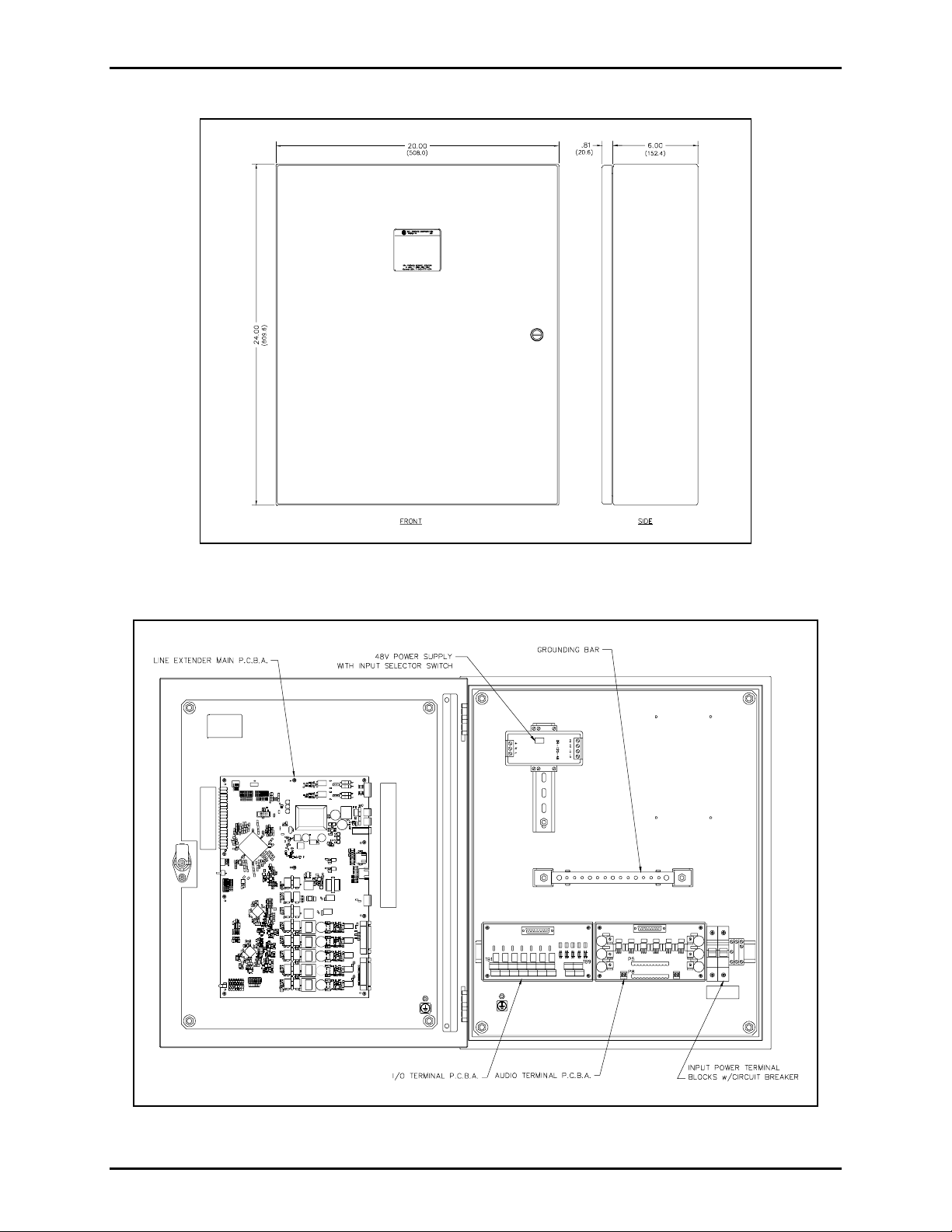
Figure 1. Model LE200 Outline Detail
Figure 2. Interior View of Components - Model LE200 (Enclosure shown open)
f:\standard ioms - current releas e\ 42004 ins t r. manuals\42004-701l2f.doc
04/09
Page 5
Pub. 42004-701L2F
M
ODEL LE200 SERIES WALL-MOUNT PAGE/PARTY® LINE EXTENDERS PAGE 3 of 50
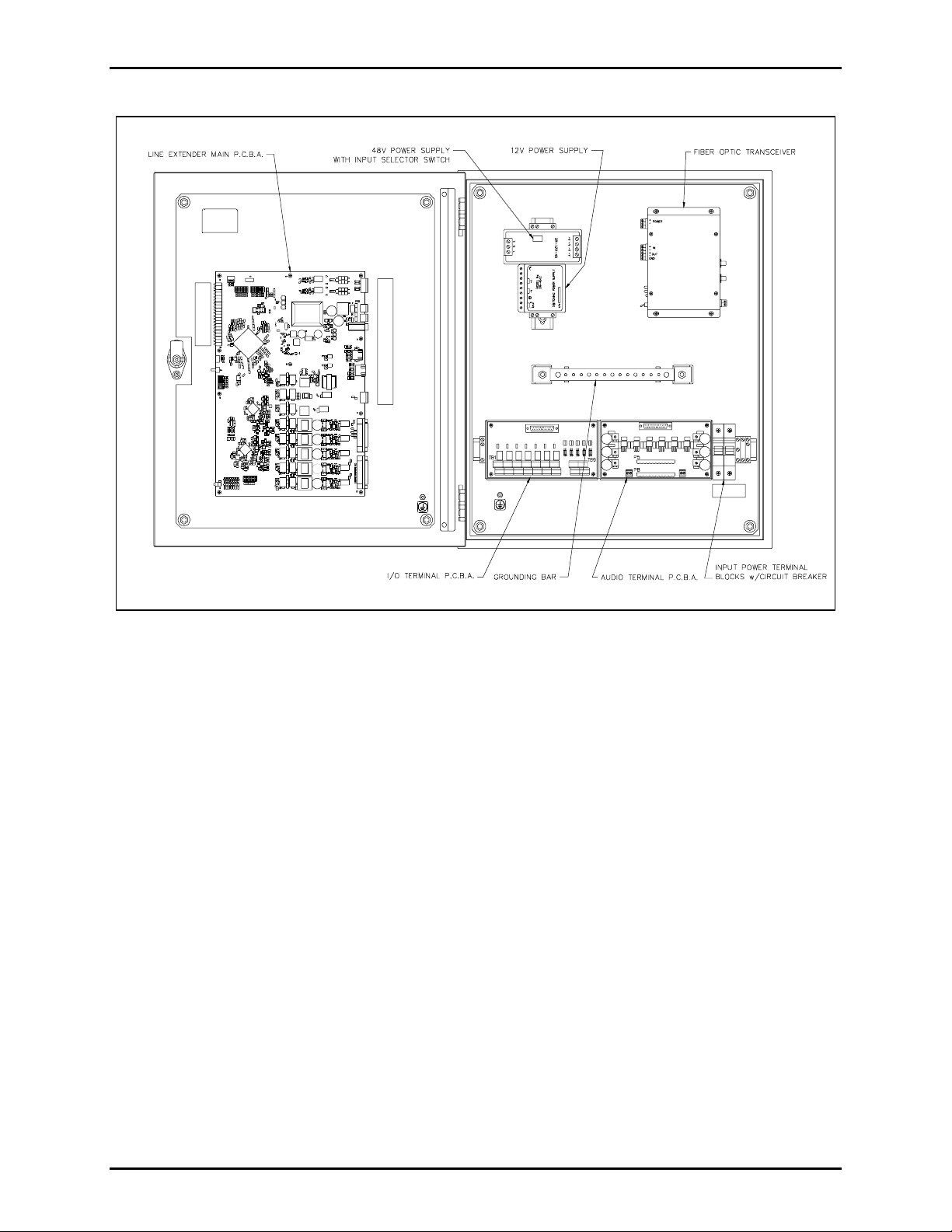
Figure 3. Interior View of Components - Models LE200-FSR and LE200-FLR (Enclosure shown open)
f:\standard ioms - current releas e\ 42004 ins t r. manuals\42004-701l2f.doc
04/09
Page 6

Pub. 42004-701L2F
M
ODEL LE200 SERIES WALL-MOUNT PAGE/PARTY® LINE EXTENDERS PAGE 4 of 50
Subcomponent Descriptions
Enclosure
The Model LE200 Series enclosures contain:
• The 69441-xxx Audio Terminal PCBA as part of the 13118-011
• The 69442-xxx I/O Terminal PCBA as part of the 13118-012
• The 69443-xxx Main PCBA
• The +48 volt power supply
• A +12 volt power supply (Models LE200-FSR and LE200-FLR only)
• A fiber modem (Models LE200-FSR and LE200-FLR only)
• Grounding connections
• Input power terminals containing 15-amp circuit breakers
69441-xxx Audio Termin al PCBA
The 69441-xxx printed circuit board is used to terminate the page and party lines of the system cable.
The 69441-xxx includes over voltage protection and line balance potentiometers for the page line and all
five party lines. Refer to Figure 5.
69442-xxx I/O Termin al PCBA
The 69442-xxx printed circuit boa r d is used to terminate the contact inputs and contact outputs. The
69442-xxx contains the relays for the contact outputs, and signal conditioning comp onents for the contact
inputs. Refer to Figure 5.
69443-xxx Main PCBA
The 69443-xxx printed circuit board contains the main logic of the Model LE200. Refer to Figure 4.
Fiber Optic Mod em Models
The Models LE200-FSR, LE200-FSR-E1, LE200-FLR and LE200-FLR-E1 include a third party fiber
modem that converts the copper T1 or E1 signals to fiber optic T1/E1 signals and vice ver sa .
• Model LE200 FSR (Multi-Mode Fiber, T1 signals)
• Model LE200 FLR (Single Mode Fiber, T1 signals)
• Model LE200-FSR-E1 (Multi-Mode Fiber, E1 signals)
• Model LE200-FLR-E1 (Single Mode Fiber, E1 signals)
+48 Volt Power Supply
The Model LE200 is powered by a +48 V power supply. A selector switch allows the power supply to
operate at either 115 V ac or 230 V ac.
+12 Volt Power Supply
The Model LE200-FSR/FLR contains a +12 V power supply for the fiber optic module. It has an
operation range from 90 V ac to 264 V ac.
f:\standard ioms - current releas e\ 42004 ins t r. manuals\42004-701l2f.doc
04/09
Page 7
Pub. 42004-701L2F
M
ODEL LE200 SERIES WALL-MOUNT PAGE/PARTY® LINE EXTENDERS PAGE 5 of 50
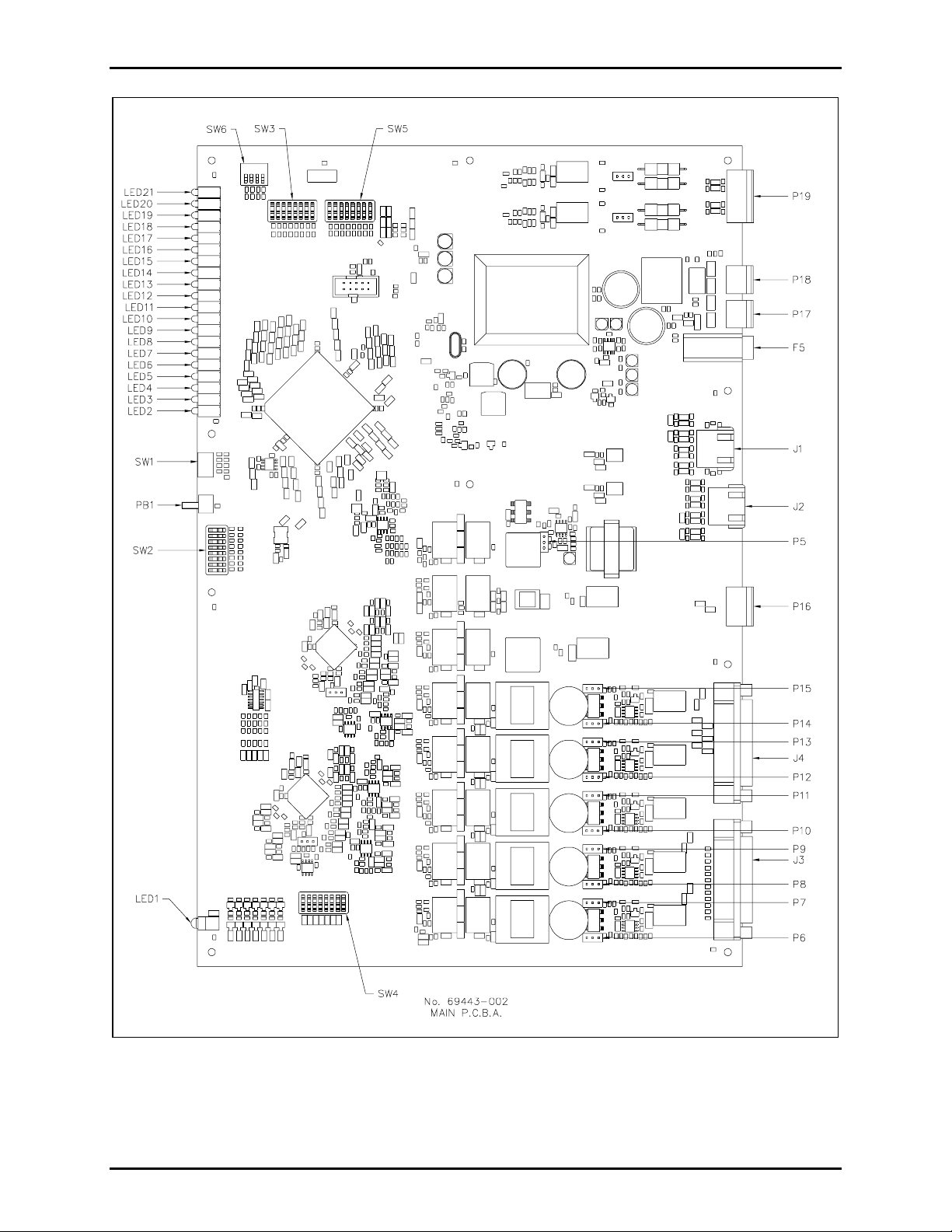
Figure 4. 69443-xxx Main PCBA
f:\standard ioms - current releas e\ 42004 ins t r. manuals\42004-701l2f.doc
04/09
Page 8
Pub. 42004-701L2F
M
ODEL LE200 SERIES WALL-MOUNT PAGE/PARTY® LINE EXTENDERS PAGE 6 of 50
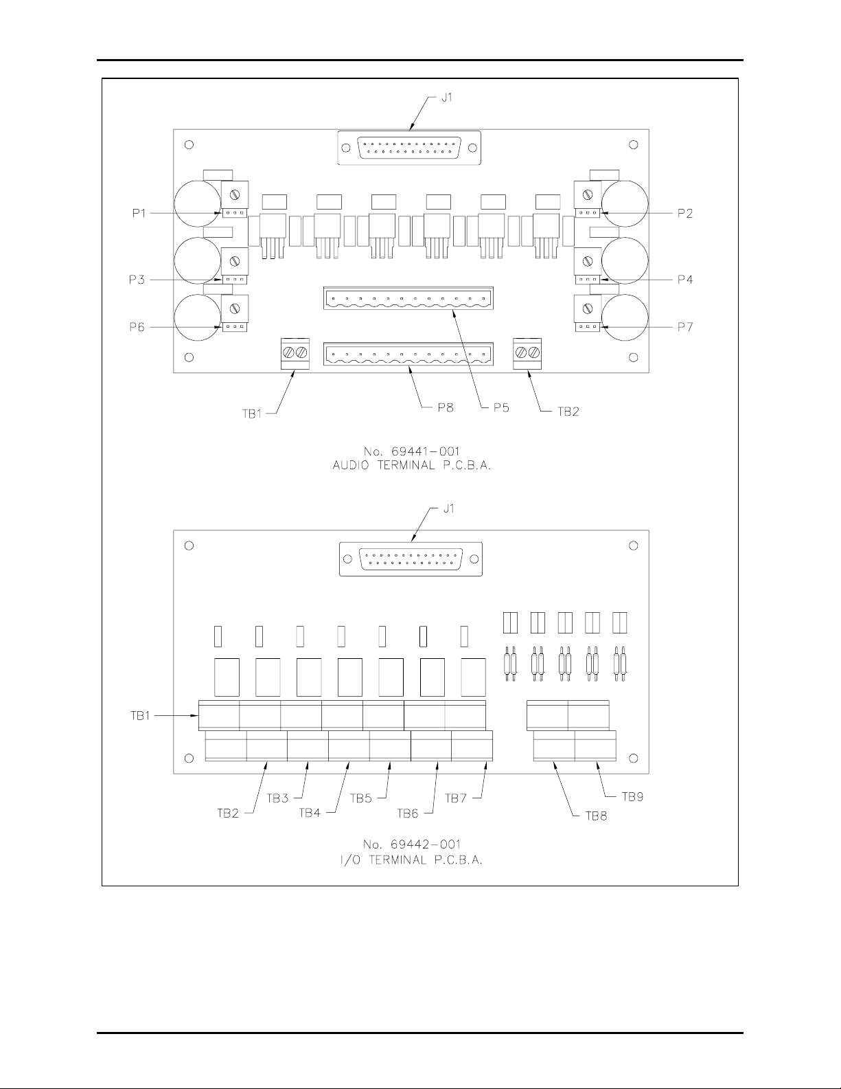
Figure 5. 69441-xxx Audio Terminal PCBA and 69442-xxx I/O Terminal PCBA
f:\standard ioms - current releas e\ 42004 ins t r. manuals\42004-701l2f.doc
04/09
Page 9
Pub. 42004-701L2F
M
ODEL LE200 SERIES WALL-MOUNT PAGE/PARTY® LINE EXTENDERS PAGE 7 of 50
Installation
ATTENTION
Instal lation s ho uld be performed by qua l ified service perso nnel only in
accordance w it h the Na tional Electri cal Code or applicabl e local codes.
Mounting
1. Unlock the front door of the enclosure using a screwdriver by rotating the lock a quarter turn
counterc loc kwise, and open t he front d oor, which is hinged on the l e ft.
2. Disconnect the ribbon cables and the ground wire connections from the interior rear panel. Remove
the four bolts that hold the rear panel in place, and set this assemb ly and the bolts aside in a safe
location.
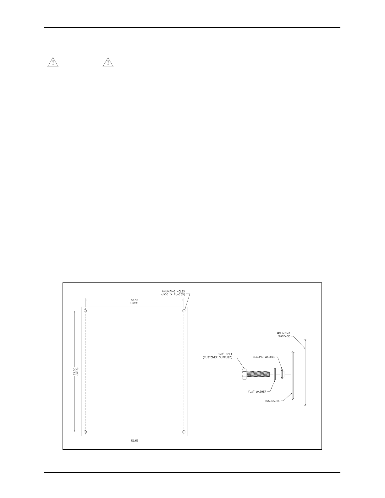
3. Position the enclosure on the mounting surface. The enclosure provides four 0.50-inch mounting
holes. Secure it with four 3/8-inch diameter bolts of the appropriate lengths for the mounting surface,
flat washers and nuts. To ensure proper sealing and enclosure protection rating, use the provided
sealing washers. Install the sealing washers inside the enclosure with the tapered cone against the
enclosure and then add the flat washer s. See Figure 6 for installation details.
4. Prepare the enclosure for cable entry. For example, if conduit is installed, create an access hole using
a metal hole punch that is equivalent in size to the conduit diameter.
5. Re-install the rear panel assembly using the four bolts removed previously. Re-attach the ribbon
cab le connectors and th e grou nd wires.
6. Pull the cables into the enclosure, and make connections per the wiring section.
7. Complete the installation by closing the front door and relocking the enclosure.
Figure 6. Mounting Details
f:\standard ioms - current releas e\ 42004 ins t r. manuals\42004-701l2f.doc
04/09
Page 10
Pub. 42004-701L2F
M
ODEL LE200 SERIES WALL-MOUNT PAGE/PARTY® LINE EXTENDERS PAGE 8 of 50
Wiring
The Model LE200 provides the interfaces for customer connections described below. All of the
terminations on the PCBAs support a wire size range of No. 24 AWG to 12 AWG.
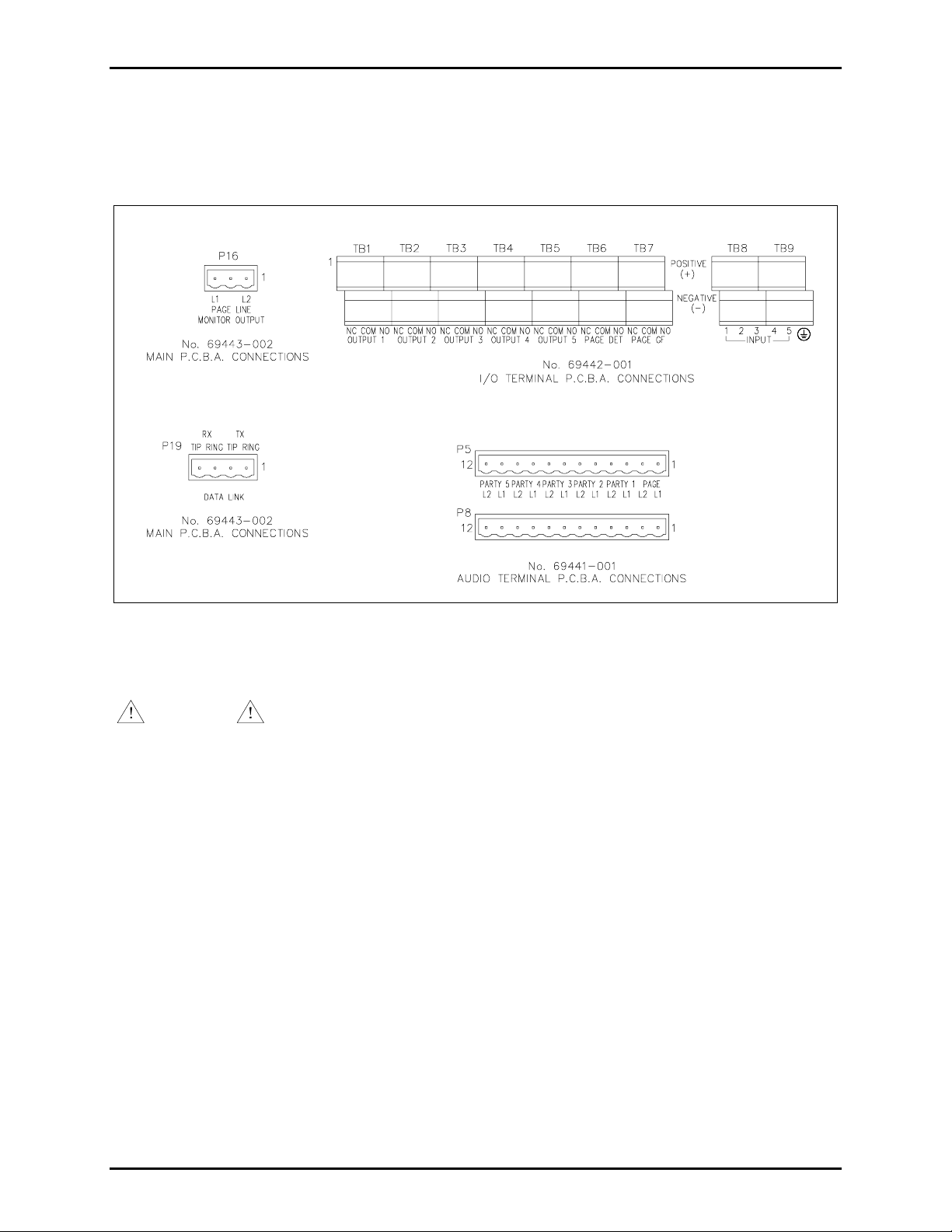
Figure 7. Wiring Connections
Power Con nections
WARNING
The input voltage selector switch must be in the appropriate position before
power is ap plied to the Line Extender.
The Line Extender provides a double-pole circuit breaker for the input power. This input voltage may be
set to either 115 V ac at 50/60 Hz or 230 V a c at 50/60 Hz via an input selector switch, which is located
on the +48 V Power Supply.
A ground and spare terminal block are located next to the double-pole circuit breaker. The orange wire
found in GAI-Tronics system cab l e can b e terminated at t his spare terminal.
f:\standard ioms - current releas e\ 42004 ins t r. manuals\42004-701l2f.doc
04/09
Page 11

Pub. 42004-701L2F
M
ODEL LE200 SERIES WALL-MOUNT PAGE/PARTY® LINE EXTENDERS PAGE 9 of 50
Table 1. Data Link on 69443-xxx PCBA
Terminal Designator Description
P19-1 Data Link TX Ring
Da ta TRANSMIT wir e pair
P19-2 Data Link TX Tip
P19-3 Data Link RX Ring
Data RECEIVE wir e pair
P19-4 Data Link RX Tip
Table 2. Page Line Monitor Output on 69443-xxx PCBA
Terminal Designator Description
P16-1 PG MON L2 Page line monitor audio output (L2)
P16-2 - No connection
P16-3 PG MON L1 Page line monitor audio output (L1)
®
Table 3. Page/Party
System Cable Connection on 69441-xxx PCBA
Refer to Figure 2 on page 2 for location of the 69441-xxx PCBA.
Terminal Designator Description
P5-1/P8-1 PAGE L1
Pa ge line audio
P5-2/P8-2 PAGE L2
P5-3/P8-3 PL1 L1
Party Line 1 audio
P5-4/P8-4 PL1 L2
P5-5/P8-5 PL2 L1
Party Line 2 audio
P5-6/P8-6 PL2 L2
P5-7/P8-7 PL3 L1
Party Line 3 audio
P5-8/P8-8 PL3 L2
P5-9/P8-9 PL4 L1
Party Line 4 audio
P5-10/P8-10 PL4 L2
P5-11/P8-11 PL5 L1
Party Line 5 audio
P5-12/P8-12 PL5 L2
f:\standard ioms - current releas e\ 42004 ins t r. manuals\42004-701l2f.doc
04/09
Page 12

Pub. 42004-701L2F
M
ODEL LE200 SERIES WALL-MOUNT PAGE/PARTY® LINE EXTENDERS PAGE 10 of 50
Table 4. Auxiliary Inputs on 69442-xxx PCBA
Refer to Figure 2 on page 2 for location of the 69442-xxx PCBA.
Terminal Designator Description
TB8 Input 1 (+)
Auxiliary input contact 1
TB8 Input 1 (-)
TB8 Input 2 (+)
Auxiliary input contact 2
TB8 Input 2 (-)
TB8 Input 3 (+)
Auxiliary input contact 3
TB8 Input 3 (-)
TB9 Input 4 (+)
Auxiliary input contact 4
TB9 Input 4 (-)
TB9 Input 5 (+)
Auxiliary input contact 5
TB9 Input 5 (-)
Table 5. Page Line Audio Detector Output on 69442-xxx PCBA
Terminal Designator Description
TB6 Output 1 N.C.
TB6 Output 1 COM
Page line audio detector output contact #1
TB6 Output 1 N.O.
TB6 Output 2 N.C.
TB6 Output 2 COM
Page line audio detector output contact #2
TB6 Output 2 N.O.
Table 6. Page Line Ground-Fault Detector Output on 69442-xxx PCBA
Terminal Designator Description
TB7 Output 1 N.C.
TB7 Output 1 COM
Pa ge line ground fault d etector output contact #1
TB7 Output 1 N.O.
TB7 Output 2 N.C.
TB7 Output 2 COM
Pa ge line ground fault d etector output contact #2
TB7 Output 2 N.O.
f:\standard ioms - current releas e\ 42004 ins t r. manuals\42004-701l2f.doc
04/09
Page 13

Pub. 42004-701L2F
M
ODEL LE200 SERIES WALL-MOUNT PAGE/PARTY® LINE EXTENDERS PAGE 11 of 50
Table 7. Auxiliary Outputs on 69442-xxx PCBA
Terminal Designator Description
TB1 Output 1 N.C.
TB1 Output 1 COM
TB1 Output 1 N.O.
TB1 Output 1 N.C.
TB1 Output 1 COM
TB1 Output 1 N.O.
TB2 Output 2 N.C.
TB2 Output 2 COM
TB2 Output 2 N.O.
TB2 Output 2 N.C.
TB2 Output 2 COM
TB2 Output 2 N.O.
TB3 Output 3 N.C.
TB3 Output 3 COM
TB3 Output 3 N.O.
TB3 Output 3 N.C.
Auxiliary output 1 - contact #1
Auxiliary output 1 - contact #2
Auxiliary output 2 - contact #1
Auxiliary output 2 - contact #2
Auxiliary output 3 - contact #1
TB3 Output 3 COM
TB3 Output 3 N.O.
TB4 Output 4 N.C.
TB4 Output 4 COM
TB4 Output 4 N.O.
TB4 Output 4 N.C.
TB4 Output 4 COM
TB4 Output 4 N.O.
TB5 Output 5 N.C.
TB5 Output 5 COM
TB5 Output 5 N.O.
TB5 Output 5 N.C.
TB5 Output 5 COM
TB5 Output 5 N.O.
Auxiliary output 3 - contact #2
Auxiliary output 4 - contact #1
Auxiliary output 4 - contact #2
Auxiliary output 5 - contact #1
Auxiliary output 5 - contact #2
f:\standard ioms - current releas e\ 42004 ins t r. manuals\42004-701l2f.doc
04/09
Page 14

Pub. 42004-701L2F
M
ODEL LE200 SERIES WALL-MOUNT PAGE/PARTY® LINE EXTENDERS PAGE 12 of 50
Fiber Optic Cable Connections
The Line Extender provides a pair of ST fiber optic connectors (one for the transmit fiber and one for the
receive fiber). Typical connections for this method are shown in Figure 9.
Figure 8. Fiber Optic Transceiver
Figure 9. Typical Fiber Optic Data Link Connection
f:\standard ioms - current releas e\ 42004 ins t r. manuals\42004-701l2f.doc
04/09
Page 15

Pub. 42004-701L2F
M
ODEL LE200 SERIES WALL-MOUNT PAGE/PARTY® LINE EXTENDERS PAGE 13 of 50
Operation
The Model LE200 Page/Party® Line Extender r equires no user interface after successful installation and
testing.
Description of F eatures
Page Line Audio Transmission
A pair of Model LE200s provides page line audio transmission between two Page/Party® system cables.
This transmiss ion is half-dupl ex oper atio n.
Half-Dupl ex Operation
When the Model LE200 detects a peak audio level equal or above a Peak Voltage Level Detection
Threshold
Time.
until it is continuously below the Peak Voltage Level Detection Threshold for the Transmission Direction
Hold Time. The DIP s w itch, SW2, loc ate d on the Main P C boar d select s Peak Voltage Level Detecti o n
Threshold and Transmission Direction Hold Time. Refer to Table 8 and Table 9 for switch setting
options.
, it immediately switches audio “on” in that direction for the Transmission Direction Hold
Audi o f rom the other direct ion is muted and ignored during that time. Audio is not switched “of f”
Training the Echo Cancellation
Overview
Line echo (also known as electric or hybrid echo) is created by the electrical circuitry connected to a twowire (full duplex) audio system. Echo is inherent in all full-duplex audio systems and is affected by the
audio line length and line impedance mismatches. The presence of audible echoes results in undesirable
audio qua lity. This kind of qual ity degradati on is inhere nt in t h e netw ork equip me nt an d e nd-u ser phone
devices.
To minimize echo, the Model LE200 performs an echo cancellation training sequence on party lines 1
through 5 . The echo ca ncellatio n training tak es approxi mate ly 15 seconds and is perf ormed aut omatically
one minute after power is applied to the LE200. This delay allows all power levels to stabilize prior to
perfor mi ng ech o c ancellation tra i ning. Echo cancellat i on can be manu all y initiated as described below.
OTE: Signal impulses are transmitted onto the audio lines during the echo cancellation training
N
sequence. Handset stations that are in use on a party line will hear the signa ls in the handset receiver. For
troubleshooting purposes, the one-minute delay may be disabled by closing DIP switch SW6-1.
Manual In itiation of E cho Cancelin g
Press and release push button PB1 on the main PC board three times. The push button must be pr essed
for at lea st one quarter second and no more than two seconds each time. The timing requirement is meant
to prevent accidental requests. If an error is made with the push-button timing, the sequence must be
repeated from the beginning.
The main board LEDs will indicate the progress of the echo canceling sequence. One column of LEDs
turns on after each push button press or release until the sequence is started. Once the sequence is started,
those LED s rema in on, and a c ountd own timer is disp layed on th e rema ining L EDs. The LED s return t o
normal op eration after the echo c ancellat ion training seque nce is complete.
f:\standard ioms - current releas e\ 42004 ins t r. manuals\42004-701l2f.doc
04/09
Page 16

Pub. 42004-701L2F
M
ODEL LE200 SERIES WALL-MOUNT PAGE/PARTY® LINE EXTENDERS PAGE 14 of 50
Table 8. Transmission Direction Hold Time on 69443-xxx PCBA
SW2-5 SW2-6 Transmission Direction Hold Time
Open (up)* Open (up)* 1280 milliseconds
Closed (down) Open (up) 640 milliseconds
Open (up) Closed (down) 160 milliseconds
Closed (down) Closed (down) 40 milliseconds
NOTE: Changes to this parameter take effect without cyc ling power.
Table 9. Peak Voltage Level Detection Threshold on 69443-xxx PCBA
SW2-7 Peak Voltage Level Detection Threshold
Open (up)* -12 dB relative to nominal
Closed (down) -24 dB relative to nominal
NOTE: Changes to this parameter take effect without cyc ling power.
Table 10. Echo Cancellation Power-On Delay Setting on 69443-xxx PCBA
SW6-1 Echo Cancellation Power-On Delay
Open* One minute
Closed No delay
NOTES: 1. Changes to this parameter take effect when cycling power.
2. *Indicates default position.
f:\standard ioms - current releas e\ 42004 ins t r. manuals\42004-701l2f.doc
04/09
Page 17

Pub. 42004-701L2F
M
ODEL LE200 SERIES WALL-MOUNT PAGE/PARTY® LINE EXTENDERS PAGE 15 of 50
Page Line Audio 600-ohm Monitor Output
The Model LE200 mixes the local and remote page line audio and broadcasts it out a 600-ohm monitor
output. For the output voltage to be at the expected level, the device attached to the monitor output
should have an input impedance of 600 ohms. DIP switch SW3 selects the monitor output’s gain.
Table 11. Monitor Output Gain Setting on 69443-xxx PCBA
SW3-8 SW3-7 SW3-6 SW3-5 Monitor Output Gain
Open* Open* Open* Open* 0 dB
Open Open Open Closed -30 dB
Open Open Closed Open -27 dB
Open Open Closed Closed -24 dB
Open Closed Open Open -21 dB
Open Closed Open Closed -18 dB
Open Closed Closed Open -15 dB
Open Closed Closed Closed -12 dB
Closed Open Open Open -9 dB
Closed Open Open Closed -6 dB
Closed Open Closed Open -3 dB
Closed Open Closed Closed 0 dB
Closed Closed Open Open +3 dB
Closed Closed Open Closed +6 dB
Closed Closed Closed Open +9 dB
Closed Closed Closed Closed +12 dB
NOTES: 1. Changes to this parameter take effect without cycling power.
2. *Indicates default position.
f:\standard ioms - current releas e\ 42004 ins t r. manuals\42004-701l2f.doc
04/09
Page 18

Pub. 42004-701L2F
M
ODEL LE200 SERIES WALL-MOUNT PAGE/PARTY® LINE EXTENDERS PAGE 16 of 50
Page Line Audio Detected Contact Output
The Model LE200 provides a contact closure output that activates whenever audio is detected on the pa ge
line. The contact can be set to close on audio detection of either the local page line, the remote page line
audio, or both. The contact remains active f or one second after the audio is no longer detected. DIP
switch SW5 enables or disables the local and remote page line audio detection contact output. Refer to
Table 12 and Table 13 below for switch setting.
Table 12. Local Page Line Audio Detect Contact on 69443-xxx PCBA
SW5-6 Page Line Audio Detect Contact Uses Local Page Audio
Open* Local page line audio activates the contact.
Closed Local page line audio does not activate the contact.
NOTES: 1. Changes to this parameter take effect without cycling power.
2. *Indicates default position.
Table 13. Remote Page Line Audio Detect Contact on 69443-xxx PCBA
SW5-7 Page Line Audio Detect Contact Uses Remote Page Audio
Open* Remote page line audio activates the contact.
Closed Remote page line audio does not activate the contact.
NOTES: 1. Changes to this parameter take effect without cycling power.
2. *Indicates default position.
f:\standard ioms - current releas e\ 42004 ins t r. manuals\42004-701l2f.doc
04/09
Page 19

Pub. 42004-701L2F
M
ODEL LE200 SERIES WALL-MOUNT PAGE/PARTY® LINE EXTENDERS PAGE 17 of 50
Page Line 50 kHz VLC Transmission
A pair of Model LE200s provides page line 50 kHz VLC transmission between two Page/Party® system
cables. The two connected Model LE200s must both be configured for 50 kHz VLC operation, and not
be configured for SmartSeries FSK transmission. If both 50 kHz VLC and SmartSeries FSK are enabled,
then neither is transmitted. DIP switch SW5 configur es page line 50 kHz VLC transmission.
Table 14. Page Line 50 kHz VLC Transmission Setting on 69443-xxx PCBA
SW5-2 Page Line 50 kHz VLC Transmission
Open* 50 kHz VLC is disabled
Closed 50 kHz VLC is enabled
NOTES: 1. Changes to this parameter take effect without cycling power.
2. *Indicates default position.
Page Line SmartSeries FSK Transmissi on
A pair of Model LE200s provides page line SmartSeries FSK transmission between two Page/Party®
system cables. The two connected Model LE200s must both be configured for SmartSeries FSK
oper atio n, and not be conf igured for 50 kH z VLC transmission. If bot h 50 kHz VL C and SmartS eries
FSK are enabled, then neither is transmitted. DIP switch SW5 configures page line SmartSeries FSK
transmission.
Table 15. Page Line SmartSeries FSK Transmission Setting on 69443-xxx PCBA
SW5-1 Page Line SmartSeries FSK Transmission
Open* SmartSer ies FSK is disabled.
Closed SmartSeries FSK is enabled.
NOTES: 1. Changes to this parameter take effect without cycling power.
2. *Indicates default position.
f:\standard ioms - current releas e\ 42004 ins t r. manuals\42004-701l2f.doc
04/09
Page 20

Pub. 42004-701L2F
M
ODEL LE200 SERIES WALL-MOUNT PAGE/PARTY® LINE EXTENDERS PAGE 18 of 50
Page Line Ground Fault Detection and Transmission
The Model LE200 Line Extenders provide page line ground fault detection on the local Page/Party®
system cable. Additionally, when a ground fault is detected, the LE200 can transmit the ground fault to
the more remote LE200 so that it is duplicated on the remote Page/Party
LE200s are connected to the same Page/Party
®
system cable segment, only one page line ground fault
dete ctor may b e enabl e d. A three-posi tion header, P5, a nd its short ing cl ip cont rol p age line ground f ault
detection. DIP switch SW5 controls page line ground fault regeneration.
Table 16. Page Line Gro und Fault Detectio n Set ting on 69443-xxx PCBA
P5 Shorting Clip Page Line Ground Fault Detection
Pins 1-2* Page line ground fault detection is disabled.
Pins 2-3 Pa ge l ine groun d f ault detection is enabled.
Removed Page line ground fault detection is disabled.
NOTES:
1. If connecting an LE200 to the same system cable segment as an ADVANCE Page/P a r ty
(PPI) card, disable the LE200 page line ground fault detector and enable the PPI card ground fault
dete c tor. If both ground fault c ircuits a re enabled s imultaneously, intermittent Sma rtSeries FSK data
err ors wi ll occur b et w e en th e PPI c a rd and SmartSer ies s tatio ns.
2. Changes to this parameter take effect without cycling power.
3. *Indicates default pos ition.
®
system cable. If multiple
®
Interface
Table 17. Page Line Gro und Fault Regeneration Setti ng on 69443-xxx PCBA
SW5-3 Page Line Ground Fault Regeneration
Open* Pa ge l ine ground faults a re not regen erat e d locally.
Closed Page l ine groun d f aults are regen erated loc ally.
NOTES:
1. The expected use of the ground fault regeneration feature is within ADVANCE systems. If used in
Page/Party
®
systems, this feature should be disabled.
2. Changes to this parameter take effect without cycling power.
3. *Indicates default pos ition.
f:\standard ioms - current releas e\ 42004 ins t r. manuals\42004-701l2f.doc
04/09
Page 21

Pub. 42004-701L2F
M
ODEL LE200 SERIES WALL-MOUNT PAGE/PARTY® LINE EXTENDERS PAGE 19 of 50
Page Line Ground Fault Detected Conta ct Output
The Model LE200 provides a contact output that activates whenever it detects a ground fault on the page
line. The DIP switch SW5 configures which page line ground faults activate this contact.
Table 18. Page Line Ground Fault Contact S e tt i ng o n 69443-xxx PCBA
SW5-4 Page Line Ground Fault Contact Uses Local Ground Fault
Open* Local page line ground faults activate the contact
Closed Local page line ground faults do not activate the contact
NOTES: 1. Changes to this parameter take effect without cycling power.
2. *Indicates default position.
Table 19. Page Line Ground Fault Contact S et ting on 69443-xxx PCBA
SW5-5 Page Line Ground Fault Contact Uses Remote Ground Fault
Open* Remote page line ground faults activate the contact
Closed Remote page line ground faults do not activate the contact
NOTES: 1. Changes to this parameter take effect without cycling power.
2. *Indicates default position.
Party Line Audio Transmission
A pair of Model LE200 Line Extenders provides full duplex party line audio transmission between two
Page/Party
During on-hook conditions of the party lines, the LE200 will mute the local party line analog circuits. If
it is necessary to have party line audio present at an LE200 even when no stations are off-hook, DIP
switch SW6-3 may be closed to disable this muting feature. This switch affects the on-hook muting
function of all five party lines.
Table 20. Party Line On-Hook M uting Setting on 69443-xxx PCBA
SW6-3 Party Line On-Hook Muting
Open* On-hook muting of local party lines is enabled.
Closed On-hook muting of local party lines is disabled.
®
system cables, for up to five party lines.
NOTES: 1. Changes to this parameter take effect without cycling power.
2. *Indicates default position.
f:\standard ioms - current releas e\ 42004 ins t r. manuals\42004-701l2f.doc
04/09
Page 22

Pub. 42004-701L2F
M
ODEL LE200 SERIES WALL-MOUNT PAGE/PARTY® LINE EXTENDERS PAGE 20 of 50
Party Line Off-hook Detection and Tran smission
The Model LE200 Line Extenders provides off-hook detection on the local Page/Party® system cable for
party lines 1 through 5. Additionally, when an off-hook condition is detected, the LE200 transmits the
off-hook condition to the more remote LE200 so that it is duplicated on the remote Page/Party
cable. If mult iple LE200s are connected to the same Page/Party
®
system cable segment, only one off-
hook detector may be enabled.
Several three-position headers and their shorting clips control party line 1 through 5 off-hook detection.
Both shorting clips associated with a particular party line must be set to the same position for proper
operation. The party lines 1-5 are configured independently.
Table 21. Party Line Off-H o ok Detection Setting on 69443-xxx PCBA
Header Pair Shorting Clip Party Line Off-Hook Detection
P15, P14 P ins 1-2* Party line #1 off-hook detection disabled.
Pins 2-3 Party line #1 off-hook detection enabled.
Removed P ar ty line #1 off-hook detection disabled.
®
system
P13, P12 P ins 1-2* Party line #2 off-hook detection disabled.
Pins 2-3 Party line #2 off-hook detection enabled.
Removed P ar ty line #2 off-hook detection disabled.
P11, P10 P ins 1-2* Party line #3 off-hook detection disabled.
Pins 2-3 Party line #3 off-hook detection enabled.
Removed P ar ty line #3 off-hook detection disabled.
P9, P8 Pins 1-2* Party line #4 off-hook detection disabled.
Pins 2-3 Party line #4 off-hook detection enabled.
Removed P ar ty line #4 off-hook detection disabled.
P7, P6 Pins 1-2* Party line #5 off-hook detection disabled.
Pins 2-3 Party line #5 off-hook detection enabled.
Removed P ar ty line #5 off-hook detection disabled.
NOTES: 1. Changes to this parameter take effect without cycling power.
2. *Indicates default position.
f:\standard ioms - current releas e\ 42004 ins t r. manuals\42004-701l2f.doc
04/09
Page 23

Pub. 42004-701L2F
M
ODEL LE200 SERIES WALL-MOUNT PAGE/PARTY® LINE EXTENDERS PAGE 21 of 50
If it is not necessary to have a Model LE200 regenerate the off-hook condition locally. DIP switch SW62 may be closed to disable this feature. This switch affects the off-hook regeneration function of all five
party lines.
Table 22. Off-Hook Regeneration on 69443-xxx PCBA
SW6-2 Off-Hook Regeneration Setting
Open* Regeneration of off-hook to local party lines is enabled.
Closed Regeneration of off-hook to local par ty lines is disabled.
NOTES: 1. Changes to this parameter take effect without cycling power.
2. *Indicates default position.
Muting Analog Lines
Pa ge and Pa rty li ne audio is muted when SW 6-4 is c lose d. This feat u re enhanc es syst e m operation in
some configurations where no page and party lines are attached to the LE200.
Table 23. Mute Analog Lines Setting on 69443-xxx PCBA
SW6-4 Mute Analog Lines Setting
Open* Muting of the analog lines is disabled.
Closed Muting of the analog lines is enabled.
NOTES: 1. Changes to this parameter take effect without cycling power.
2. *Indicates default position.
Line Connection Relays
The Model LE200 has relays that disconnect the page and party line connections from the main PC board
for s pecial appl ications. This would apply to sin gle party l ine systems or any applic ati on in which a
page/5-party cable is not connected to the line extender. The DIP switch, SW4, controls audio line
connections. Also, if no Page/Party
analog circuits.
N
OTE: When a par ty line is disconne c ted from the field wirin g, that pa r ty line ’s off-hook detect or should
be disable d. Otherwise, t hat pa r ty line will appear permanently of f-hook.
®
cable is connected, DIP switch SW6-4 should be closed to mute the
f:\standard ioms - current releas e\ 42004 ins t r. manuals\42004-701l2f.doc
04/09
Page 24

Pub. 42004-701L2F
M
ODEL LE200 SERIES WALL-MOUNT PAGE/PARTY® LINE EXTENDERS PAGE 22 of 50
Table 24. Line Connection Relay Enable SW4 DIP Switch Setting on 69443-xxx PCBA
SW4 Switch Setting Field Wiring Connection
SW4-1 Open Party line #5 is not connected to the field wiring.
Closed* Party line #5 is connected to the field wiring.
SW4-2 Open Party line #4 is not connected to the field wiring.
Closed* Party line #4 is connected to the field wiring.
SW4-3 Open Party line #3 is not connected to the field wiring.
Closed* Party line #3 is connected to the field wiring.
SW4-4 Open Party line #2 is not connected to the field wiring.
Closed* Party line #2 is connected to the field wiring.
SW4-5 Open Party line #1 is not connected to the field wiring.
Closed* Party line #1 is connected to the field wiring.
SW4-6 Open The page line is not connected to the f i eld wiring.
Closed* The page line is connected to the field wiri ng.
SW4-7 Open The monitor output is not connected to the f i eld wiring.
Closed* The monitor outpu t is connected to the field wiring.
SW4-8 Open Not used.
Closed* Not used.
NOTES: 1. Changes to this parameter take effect without cycling power.
2. *Indicates default position.
f:\standard ioms - current releas e\ 42004 ins t r. manuals\42004-701l2f.doc
04/09
Page 25

Pub. 42004-701L2F
M
ODEL LE200 SERIES WALL-MOUNT PAGE/PARTY® LINE EXTENDERS PAGE 23 of 50
Page/Party® Line Balance
For proper operation, th e l ine resistanc e for t he page and part y lines s hould be set c lose to 33 o hms. The
Model LE200 provides the line balance resistors needed on the page line and five party lines. These line
balance resistors are located on the 69441-xxx board next to the pa ge and party line terminal blocks. The
line balance resistors are adjustable or can be disabled. Several headers, shorting clips, and
potentiometers control the line balance settings.
®
Table 25. Page/Party
Header Shorting Clip Line Balance Setting
P6 Pins 1-2* Party line #5 line balance resistor disabled.
Pins 2-3 Party line #5 line balance resistor enabled.
Removed Party line #5 line balance resistor disabled.
P3 Pins 1-2* Party line #4 line balance resistor disabled.
Pins 2-3 Party line #4 line balance resistor enabled.
Line Balance Setting on 69441-xxx PCBA
Removed Party line #4 line balance resistor disabled.
P1 Pins 1-2* Party line #3 line balance resistor disabled.
Pins 2-3 Party line #3 line balance resistor enabled.
Removed Party line #3 line balance resistor disabled.
P2 Pins 1-2* Party line #2 line balance resistor disabled.
Pins 2-3 Party line #2 line balance resistor enabled.
Removed Party line #2 line balance resistor disabled.
P4 Pins 1-2* Party line #1 line balance resistor disabled.
Pins 2-3 Party line #1 line balance resistor enabled.
Removed Party line #1 line balance resistor disabled.
P7 Pins 1- 2* Pa ge l ine li ne balance resis tor disabled.
Pins 2-3 Page lin e line balance r es i stor enabled.
Removed Page line line balance resistor disabled.
NOTES: 1. Changes to this parameter take effect without cycling power.
2. *Indicates default position.
f:\standard ioms - current releas e\ 42004 ins t r. manuals\42004-701l2f.doc
04/09
Page 26

Pub. 42004-701L2F
M
ODEL LE200 SERIES WALL-MOUNT PAGE/PARTY® LINE EXTENDERS PAGE 24 of 50
Contact Closure Input Transmission
A pair of Model LE200s provides contact closure detection and transmission for five contact closure
inputs. An input contact closure on the local Model LE200 results in the corresponding output contact
becoming active on the remote Model LE200.
N
OTE: Should the data link between the two LE200s break, any active output contacts will deactivate.
Data Link Technology used with LE200 Line Extenders
The LE200 contains two different data link types for connecting line extenders. The connection scheme
of the line extenders determines which data link(s) should be used. The two data types are T1/E1 and
Low Voltage D i ffere ntial Signal ing (LVDS) . It i s possible to use both types at the same time to achieve
complex system architectures. Each data type, intended use, and the applicable switch settings are
described below.
T1/E1 Digital Lin k
The T1/E1 data link connection is the most common and is used when one pair of Model LE200s is
connected together. The T1/E1 carrier technology uses dedicated copper cable or fiber optic cable when
equipped with a T1/E1 fiber optic modem. The distance between line extenders determines the type of
connection needed. Copper wire connections require a 2-pair cable and will operate at up to 6000 feet
using No. 22 AWG wire. For distances greater than 6000 feet, a T1/E1 fiber optic modem and fiber optic
cable must be used.
OTE: The Model LE200 is NOT designed for use with the public switched telephone network.
N
Low Voltage Diff erential Signaling ( LVDS) Data Link
The LVDS data link connection is used to connect two or more LE200s located within 10 meters of each
oth er. The L VD S dat a link requ ires a straight-through shiel d e d CAT 5e cab le between line exten d ers.
Each line extender contains an LVDS data “in” port and an LVDS data “out” port. The “out” port of the
first line extender to the “in” port of the next line extender. This connection scheme is repeated to link
mult ipl e li ne ext e nd ers . Typicall y th is con ne ct io n sc heme is us ed when mu lt ip le li ne ext e nd ers ar e
installed in a central location.
Setting up the Da ta Link(s)
The data links between line extenders must be configured using multiple DIP switch settings to determine
the clock source. Each LE200 must have exactly one clock source for its main processing logic. There
ar e three choices for the cloc k: an inter nal oscilla tor, a T1/E1 clock, or the LVD S “in” clock.
There are three possible choices for the source of this clock: the local Model LE200, the remote Model
LE200, or an external clock source on the T1/E1 link connecting two Model LE200s. If more than two
Model LE200s are connected using the T1/E1 data link and LVDS data link, then all must have their
clock derived from a single source.
An unused T1/E 1 conn ect i o n can be left open (not termina t ed).
f:\standard ioms - current releas e\ 42004 ins t r. manuals\42004-701l2f.doc
04/09
Page 27

Pub. 42004-701L2F
M
ODEL LE200 SERIES WALL-MOUNT PAGE/PARTY® LINE EXTENDERS PAGE 25 of 50
The T1/E1 and LVDS data link settings are described in the following paragraphs.
T1 Data Link Settings
DIP switch, SW2, on the main PC board selects two line-length related parameters for the T1 format.
Line length refers to the distance between the two LE200s connecting over copper cable or the cable
distance between the LE200 and the fiber optic modem if using fiber optics to connect the line extenders.
Table 26. T1/E1 Line Length Setting on 69443-xxx PCBA
SW2-1 SW2-2 SW2-3 T1 Line Length
Open (up)* Open (up)* Open (up)* DSX-1 (0 to 133 feet)
Closed (down) Open (up) Open (up) DSX-1 (133 to 266 feet)
Open (up) Closed (down) Open (up) DSX-1 (266 to 399 feet)
Closed (down) Closed (down) Open (up) DSX-1 (399 to 533 feet)
Open (up) Open (up) Closed (down) DSX-1 (533 to 655+ feet)
NOTES: 1. Changes to this parameter take effect without cycling power.
2. *Indicates default position.
3. These switches have no effect in E1 mode.
Table 27. Receive Equalizer Gai n Limit Setting on 69443-xxx PCBA
SW2-4
Receive Equalizer Gain Limit
T1 Mode E1 Mode
Open (up)* -36 dB (long haul) -12 dB (short haul)
Closed (down) -15 dB (limited long haul) -43 dB (long haul)
NOTES: 1. Changes to this parameter take effect without cycling power.
2. *Indicates default position.
f:\standard ioms - current releas e\ 42004 ins t r. manuals\42004-701l2f.doc
04/09
Page 28

Pub. 42004-701L2F
M
ODEL LE200 SERIES WALL-MOUNT PAGE/PARTY® LINE EXTENDERS PAGE 26 of 50
DIP switch SW3 selects T1/E1 clock related parameters. For each pair of line extenders, only one line
ext e nder c an be c lock s ource (master).
Table 28. Use T1/E1 Clock as Board’s Master Clock Source Setting on 69443-xxx PCB A
SW3-1 T1/E1 Clock as Board’s Master Clock Source
Open * The recovered clock is not t he boa rd’s master clo ck source.
Closed The recovere d clock is the board's master cl ock source.
NOTES: 1. Changes to this parameter take effect after cycling power.
2. *Indicates default position.
Table 29. Use the Board’s Master Clock as the T1/E1 Transmit Clock Setting on 69443-xxx PCBA
SW3-2 Use the Board’s Master Clock as the T1/E1 Transmit Clock
Open * T he board’s master c lock is the t rans mit clock (clock mast er).
Closed The remote (recovered) c lock is the transmit clock (cloc k sla v e) .
NOTES: 1. Changes to this parameter take effect after cycling power.
2. *Indicates default position.
DIP switch, SW5, on the main PC board provides the selection of which data link format is to be used for
the digital audio transmission. The T1 (1.544 Mbps) format is most commonly used in North America.
The E1 (2.048 Mbps) format is most commonly used in Europe. It is important that these settings match
between the connected LE200s and any interface equipment between.
Table 30. Digital Audio Format Setting on 69443-xxx PCBA
SW5-8 Digital Audio Format
Open* T1 Mode (1.544Mbps, 24-channel)
Closed E1 Mode (2.048Mbps, 32-channel)
NOTES: 1. Changes to this parameter take effect after cycling power.
2. *Indicates default position.
f:\standard ioms - current releas e\ 42004 ins t r. manuals\42004-701l2f.doc
04/09
Page 29

Pub. 42004-701L2F
M
ODEL LE200 SERIES WALL-MOUNT PAGE/PARTY® LINE EXTENDERS PAGE 27 of 50
Headers P20 and P21 control the grounding of the T1/E1 lines. Grounding the T1/E1 lines may reduce
emissions if that is an instal lation conc ern.
Table 31. T1/E1 Line Grounding on 69443-xxx PCBA
Header Shorting Clip Grounding Condition
P20 1-2 * T1/E1 Rx line floati ng.
2-3 T1/E 1 R x line gr ound e d.
Removed T1/E1 Rx lin e floa ting.
P21 1-2* T1/E1 Tx line floating.
2-3 T1/E1 Tx line grounded.
Removed T1/E1 Tx line floating.
*Indicates default pos ition.
NOTE
Do not connect t he T1/ E1 transmit signal to the T1/E1 receive signal on the same
Model LE200. Doing so creates a feedback path that usually results in extremely loud oscillations
on the page line and the party lines. The contact outputs may a lso act ivate.
NOTE
Do not ground the T1/E1 lines at bo th ends. Doing so will create a g round loop.
An unused T1 connection can be left open (n ot t erminated).
f:\standard ioms - current releas e\ 42004 ins t r. manuals\42004-701l2f.doc
04/09
Page 30

Pub. 42004-701L2F
M
ODEL LE200 SERIES WALL-MOUNT PAGE/PARTY® LINE EXTENDERS PAGE 28 of 50
LVDS Data Link Se ttings
DIP switch, SW3, selects the LVDS related para meters which are the LVDS “in” clock and the LVDS
“out” port ena ble or disable. The LVDS “in” port is disabled unless it is receiving a signal from LVDS
“out” of a different Model LE200.
Table 32. Use the LVDS “in” Clock as Board’s Master Clock Source Setting on 69443-xxx PCBA
SW3-3 LVDS “in” as Board’s Master Clock Source
Open * The L VD S “in” clock is not the board’s ma ster clock source.
Closed The LVD S “in” clock is the boa rd’s master clo ck sou rce.
NOTES: 1. Changes to this parameter take effect after cycling power.
2. *Indicates default position.
Table 33. Enable LVDS “out” Setting on 69443-xxx PCB A
SW3-4 Enable LVDS “out”
Open* LVDS “out” is disabl ed.
Closed LVDS “out” is enabled.
NOTES: 1. Changes to this parameter take effect without cycling power.
2. *Indicates default position.
NOTE
Do not connect LVDS “in” to LVDS “out” on the same Model LE200. Doing so
creates a feedback path that usually results in (extremely loud) oscillations on the page line, all party
lines, and poss i bly the co ntact outputs.
Unused LVDS ports can be left open.
LVDS Port I ndicators
Each LVDS port has two LEDs. The green LED is ON when the LE200 detects a signal from the remote
LE200 on that LVDS port. The yellow/orange LED is ON when the local LE200 is the source of page
line data (Sma rtSeries FSK or 50 kHz VLC) ou t of that L VD S port.
f:\standard ioms - current releas e\ 42004 ins t r. manuals\42004-701l2f.doc
04/09
Page 31

Pub. 42004-701L2F
M
ODEL LE200 SERIES WALL-MOUNT PAGE/PARTY® LINE EXTENDERS PAGE 29 of 50
Fiber Optic Modem Set-Up (Models LE2 00-FSR and LE200-FLR)
The Fiber Optic Transceiver contains a 9-position DIP switch on the front panel that is ma r ked SET UP.
These switches must be set according to the following table to insure proper operation of the Model
LE200-FSR or LE200-FLR Line Extender.
Table 34. Front Panel DIP Switch Settings Model 9637/T1 or Model 9637/E1
Switch # Function Correct Setting
1 Sets the signal encoding format:
• UP or OFF – B8ZS (T1 only); HDB3 (E1 only)
• DOWN or ON – AMI
2 Enables the TAOS test mode:
• UP or OFF – N ormal operation
• DOWN or ON – Unit will transmit all logic ones
from the data port
3 Enables Local Loopback Test Mode:
• UP or OFF – N ormal operation
• DOWN or ON – Used only for testing purposes. The
data input is looped back to the data output. Use the
front panel toggle switch to enable the loopback test.
Switches 4–6 are the Line Build-out selection for T1.
They must be set according to the twisted pair cable
length between the data port and the LE200 Main PCBA.
Length S4 S5 S6
0–133 feet OFF ON ON
4, 5, 6
134–266 feet ON OFF OFF
267–399 feet ON OFF ON
400–533 feet ON ON OFF
UP or OFF – B8ZS (T1);
HDB3 (E1)
UP or OFF – N ormal operation
UP or OFF – N ormal operation
T1 S4 S5 S6
0–133 feet OFF ON ON
E1 S4 S5 S6
Not used OFF OFF OFF
534–655 feet ON ON ON
This feature is not available for E1. However, switches
must be in th e O FF positi on for proper opera tion.
7
Not used for T1 or E1 but must be OFF for proper
operation.
8
Selects b etween B iphase-M and Bipha se-L optical
cloc k/da ta enc oding:
• UP or OFF – Biphase M encoding
• DOWN or ON – Biphase L encoding
9
Master/Slave S witch ( T1 onl y):
• UP or OFF – Master
• DOWN or ON – Slave
Not used (E1)
f:\standard ioms - current releas e\ 42004 ins t r. manuals\42004-701l2f.doc
04/09
OFF
UP or OFF – Biphase M
encoding
DOWN or ON – Slave (T1)
UP or OFF (E1)
Page 32

Pub. 42004-701L2F
M
ODEL LE200 SERIES WALL-MOUNT PAGE/PARTY® LINE EXTENDERS PAGE 30 of 50
Loopback T est Switch
A 3-position toggle switch marked LPBK TEST is loca ted on the fr o nt pane l. This s witch must b e set to
the center position labeled OPR to insure proper operation of the Model LE200-FSR or LE200-FLR Line
Extender.
Indicators
Table 35. Model 9637/T1 or Model 9637/E1 Indicator Function Table
Indicator Function
OPT CD This is the optical carrier detect indicator.
• RED - indicates t he abs e nce of a good optical signal.
• GREEN - indicates the presence of a good optical signal.
DATA IN This is the data input detect indicator.
• RED - indicates t he abs e nce of an inpu t si gnal.
• GREEN - indicates the presence of an input signal.
BPV
When illuminated RE D , it indi c ates the pr esence of Bipolar Violations on
the input signal. This could be a result of a faulty input cable or that the
modem’s signal encoding switch (S1) is set incorrectly.
DATA AIS OUT
When illuminated YELLOW, all logic ones are being transmitted from the
Data I/O Output port. Switch 2 is set to DOWN position.
DATA AIS IN
When illuminated YELLOW, all logic ones are being received at the Data
I/O Input port. Switch 2 is set to DOWN position.
OPT AIS IN
When illuminated YELLOW, an optical AIS signal is being received.
Typically an indication of a successful loopback test
TEST When illuminated YELLOW, the unit is in a Test mode.
Verificatio n of Proper Operation
Under normal operating conditions, the DATA IN and OPT CD indicators will be GREEN. All other
LED indicators will be OFF.
f:\standard ioms - current releas e\ 42004 ins t r. manuals\42004-701l2f.doc
04/09
Page 33

Pub. 42004-701L2F
M
ODEL LE200 SERIES WALL-MOUNT PAGE/PARTY® LINE EXTENDERS PAGE 31 of 50
Typical Clock Setting Information
The following section shows the most common line extender connection schemes and the expected T1/E1
and LVDS data line parameters for each. Consult the applicable tables above to determine the correct
switch settings. Consult GAI-Tronics for technical support of connection schemes not shown in this
manual.
Point-to-P oint Page/P arty® System Connection
®
Figure 10. Point -to- Point Page/Party
Table 36. Point-to- Point Page/Party
®
System Connection Table
System Connection
Parameter Switch Configuration Description
T1 Line
SW2 Determined by installation distance between LE200s.
Length
T1 /E1 Cl oc k
Source
SW3-1
SW3-2
• Unit A is the master clock source: SW3-1 (open) SW3-2 (open)
• Unit B uses the T1/E1 clock from Unit A: SW3-1 (closed) SW3-2
(closed)
LVDS Clock
Source
SW3-3
SW3-4
Not used - disable both LVDS “in” and “out”: SW3-3 (open) SW3-4 (open)
f:\standard ioms - current releas e\ 42004 ins t r. manuals\42004-701l2f.doc
04/09
Page 34

Pub. 42004-701L2F
M
ODEL LE200 SERIES WALL-MOUNT PAGE/PARTY® LINE EXTENDERS PAGE 32 of 50
Point to Multi- point Page/Party® System Connection
Figure 11. Point to Multi-point Page/Pa r ty
®
System Connection
Table 37. Point to Multi-point Page/Party
®
System Connection Table
Parameter Switch Configuration Description
T1 Line
Length
SW2
Determined by installation distance between each pair of line extenders:
• A to D
• B to E
• C to F
T1 /E1 Cl oc k
Source
SW3-1
SW3-2
• Units A, B, and C are the master clock sources: SW3-1 (open) SW3-2
(open)
• Unit D uses the T1/E1 clock from Unit A: SW3-1 (closed) SW3-2 (closed)
• Unit E uses the T1/E1 clock from Unit B: SW3-1 (closed) SW3-2 (closed)
• Unit F uses the T 1/E1 clock from Unit C: SW3-1 (closed) SW3-2 (closed)
LVDS
Clock
Source
SW3-3
SW3-4
LVDS clock is used b etween u n its A, B and C.
• Unit A - “in” disabled, “out” enabled: SW3-3 (open) SW3-4 (closed)
• Unit B - “in” enabled, “out” enabled: SW3-3 (closed) SW3-4 (closed)
• Unit C - “in” enabled, “out” disabled: SW3-3 (closed) SW3-4 (open)
Mute
Analog
SW6-4
Units B and C are muted since no Page/Party® cable is connected:
SW6-4 (closed).
Lines
f:\standard ioms - current releas e\ 42004 ins t r. manuals\42004-701l2f.doc
04/09
Page 35

Pub. 42004-701L2F
M
ODEL LE200 SERIES WALL-MOUNT PAGE/PARTY® LINE EXTENDERS PAGE 33 of 50
Series Connec tion of Page/Party® System
Figure 12. Series Connection of Page/Party
®
System
®
Table 38. Series Connection o f Page/ P ar ty
System Table
Parameter Switch Configuration Description
T1 Line
Length
SW2 Determined by installation distance between each pair of line extenders:
• A to B
• C to D
T1 /E1 Cl oc k
Source
SW3-1
SW3-2
• Units A and C are the master clock sources: SW3-1 (open) SW3-2 (open)
• Unit B uses the T1/E1 clock from Unit A: SW3-1 (closed) SW3-2
(closed)
• Unit D uses the T1/E1 clock from Unit C: SW3-1 (closed) SW3-2
(closed)
LVDS Clock
Source
SW3-3
SW3-4
LVDS clock is used b etween u n its B and C:
• Unit B - “in” disabled, “out” enabled: SW3-3 (open) SW3-4 (closed)
• Unit C - “in” enabled, “out” disabled: SW3-3 (closed) SW3-4 (open)
Mute Analog
Lines
SW6-4
Unit C is muted since no Page/Party
SW6-4 (closed).
®
cable is connected:
f:\standard ioms - current releas e\ 42004 ins t r. manuals\42004-701l2f.doc
04/09
Page 36

Pub. 42004-701L2F
M
ODEL LE200 SERIES WALL-MOUNT PAGE/PARTY® LINE EXTENDERS PAGE 34 of 50
Rules for Interconnecting more than T wo Model LE200s
When connecting more than two Model LE200s together, these rules must be followed.
• A maximum of two Model LE200 pairs can be connected in series when the series connections are
made using Page/Party
®
cable as shown below.
Figure 13 . Maximum S eries C onnections
When Model LE200s are connected in series, a problem can arise when training echo cancellation. If
more than one Model LE200 is training echo cancellation on a signal line at the same time, then none
of them will train echo canc ellation properly. To prevent this, power each line extender one at a time.
Wait for the echo cancellation to complete on the first line extender before powering the second.
• A maximum of eight
pairs of Model LE200s can be connected in parallel. Parallel connections must
be made using the LVDS link and the T1/E1 link as shown below.
Figure 14. Maximum Parallel Connections
f:\standard ioms - current releas e\ 42004 ins t r. manuals\42004-701l2f.doc
04/09
Page 37

Pub. 42004-701L2F
M
ODEL LE200 SERIES WALL-MOUNT PAGE/PARTY® LINE EXTENDERS PAGE 35 of 50
• A maximum of 16 Model LE200s can be connected within a single z one or Page/Party® subsystem
®
• Avoid having more than one Model LE200 connected to a particular Page/Party
ca ble. Instead, use
th e LVD S link w hen ever p o ssi bl e.
• Line extenders can NOT be wired in a loop architecture for redundant connections as shown below:
Figure 15. Inva lid Loop Conne c tio n of Page/Party
®
Systems
• All contact input states are ORed together to determine a contact output state.
• All remote page line audio detected states are ORed together to determine the remote page line audio
detected st ate used by that contact output .
• All remote page line ground fault states are ORed together to determine the remote page line ground
fault state used by that contact output.
• When enabled, 50 kHz VLC signal on any page line is transmitted to all page lines.
• SmartSeries FSK data on any page line is transmitted to all page lines.
• Manual retraining of echo cancellation at one Model LE200 also requests it at all digitally
interconnected Model LE200s.
f:\standard ioms - current releas e\ 42004 ins t r. manuals\42004-701l2f.doc
04/09
Page 38

Pub. 42004-701L2F
M
ODEL LE200 SERIES WALL-MOUNT PAGE/PARTY® LINE EXTENDERS PAGE 36 of 50
Summary of PC Board Connections and Settings
Table 39. Page/Party Termination PCBA (Model 69441-xxx)
Refer to Figure 5 for comp onent locations.
Designator Type Function
J1 DB-25 connector Connect to J4 on Main PCBA (69443-xxx) via ribbon cable.
P1 Jumper clip Part y line #3 line balance resistor enabled/disabled
P2 Jumper clip Part y line #2 line balance resistor enabled/disabled
P3 Jumper clip Part y line #4 line balance resistor enabled/disabled
P4 Jumper clip Part y line #1 line balance resistor enabled/disabled
P6 Jumper clip Part y line #5 line balance resistor enabled/disabled
P7 J umper c lip Page line balance resistor e nable d/disable d
P5 & P8 Ter minal b lock Pa ge L ine - T ermi nals 1 and 2
Party Line 1 - Terminals 3 and 4
Party Line 2 - Terminals 5 and 6
Party Line 3 - Terminals 7 and 8
Party Line 4 - Terminals 9 and 10
Party Line 5 - Terminals 11 and 12
R3 Potentiometer Party line #3 line balance resistance
R4 Potentiometer Party line #2 line balance resistance
R19 Potentiometer Party line #4 line balance resistance
R20 Potentiometer Party line #1 line balance resistance
R23 Potentiometer Party line #5 line balance resistance
R24 Potentiometer Page line, line balance resistance
TB1 T erminal block C hassis ground - Terminals 1 and 2
TB2 T erminal block C hassis ground - Terminals 1 and 2
f:\standard ioms - current releas e\ 42004 ins t r. manuals\42004-701l2f.doc
04/09
Page 39

Pub. 42004-701L2F
M
ODEL LE200 SERIES WALL-MOUNT PAGE/PARTY® LINE EXTENDERS PAGE 37 of 50
Table 40. Input/Output Terminations PCBA (Model 69442-xxx)
Refer to Figure 5 for comp onent locations.
Designator Type Function
J1 DB-25 connector Connect to J3 on Main PCBA (69443-xxx) via ribbon cable
TB1 Terminal block
Field connections for contact output #1
The board’s silkscreen indicates the connections; the pin
numb ers a re not la bel e d.
TB2 Terminal block
Field connections for contact output #2
The board’s silkscreen indicates the connections; the pin
numb ers a re not la bel e d.
TB3 Terminal block
Field connections for contact output #3
The board’s silkscreen indicates the connections; the pin
numb ers a re not la bel e d.
TB4 Terminal block
Field connections for contact output #4
The board’s silkscreen indicates the connections; the pin
numb ers a re not la bel e d.
TB5 Terminal block
Field connections for contact output #5
The board’s silkscreen indicates the connections; the pin
numb ers a re not la bel e d.
TB6 Terminal block
Field connections for page audio detected contact output
The board’s silkscreen indicates the connections; the pin
numb ers a re not la bel e d.
TB7 Terminal block
Field connections for page ground fault contact output
The board’s silkscreen indicates the connections; the pin
numb ers a re not la bel e d.
TB8 Terminal block
Field connections for contact inputs #1, #2, and #3
The board’s silkscreen indicates the connections; the pin
numb ers a re not la bel e d.
TB9 Terminal block
Field connections for contact inputs #4 a nd #5
Field connections for chassis ground
The board’s silkscreen indicates the connections; the pin
numb ers a re not la bel e d.
f:\standard ioms - current releas e\ 42004 ins t r. manuals\42004-701l2f.doc
04/09
Page 40

Pub. 42004-701L2F
M
ODEL LE200 SERIES WALL-MOUNT PAGE/PARTY® LINE EXTENDERS PAGE 38 of 50
Table 41. Main Processing PCBA (Model 69443-xxx)
Refer to Figure 4 for comp onent locations.
Designator Type Function
J1 RJ45 receptacle LVDS data “out”
J2 RJ45 receptacle LVDS data “in”
J3
J4
DB-25
connector
DB-25
connector
Connect to J1 on Input/Output Termination PCBA (Model 69442xxx) via 25-pin ribbon cable.
Connect to J1 on Page/Pa rty
®
Termination PCBA (Model 69441-
xxx) via 25-pin ribbon cable.
P1 N/A Not installed
P2 Post header No connection - used during production testing of PC board)
P3 N/A Not installed
P4 Post header No connection - used during production testing of PC board)
P5 J umper c lip P age line ground f ault detector e nabled/dis abl e d.
P6, P7 Jumper clip Party line #5 off-hook detector enabled/disabled.
P8, P9 Jumper clip Party line #4 off-hook detector enabled/disabled.
P10, P11 Jumper clip Party line #3 off-hook detector enabled/disabled.
P12, P13 Jumper clip Party line #2 off-hook detector enabled/disabled.
P14, P15 Jumper clip Party line #1 off-hook detector enabled/disabled.
P16 Terminal block
Page line monitor output - Terminals 1 and 3
No connection - Terminal 2
P17, P18 Terminal block
P19 Terminal block
Power 48 V dc (+) - Terminal 1
Power 48 V dc (-) - Terminal 2
T1/E1 Data TX (ring) - Terminal 1
WARNING
Turn off power before connecting
and disconnect i ng.
T1/E1 Data TX (tip) - Terminal 2
T1 /E1 Data RX ( ring) - Ter minal 3
T1/E1 Data RX (tip) - Terminal 4
P20 Jumper clip T1/E1 receive transformer center tap floating/grounded.
P21 Jumper clip T1/E1 transmit transformer center tap floa ting/grounded.
PB1
Push-button
Used to retrain the echo cancellation circuit.
switch
SW1
Rotary HEX
Used for diagnostic purposes. Set to 0 during normal operation
switch
f:\standard ioms - current releas e\ 42004 ins t r. manuals\42004-701l2f.doc
04/09
Page 41

Pub. 42004-701L2F
M
ODEL LE200 SERIES WALL-MOUNT PAGE/PARTY® LINE EXTENDERS PAGE 39 of 50
Designator Type Function
SW2
SW3
SW4
8-position
DIP switch
8-position
DIP switch
8-position
DIP switch
Position 1 - T1 line build out bit 0
Position 2 - T1 line build out bit 1
Position 3 - T1 line build out bit 2
Position 4 - T1/E1 receive equalizer gain limit
Position 5 - Page audio hold ti me ( bit 1)
Test waveform select (bit 1)
Position 6 - Page audio hold ti me ( bit 2)
Test waveform select (bit 1)
Positio n 7 - Page audio detect thr eshold
Position 8 - Test waveform enable
Positio n 1 - Board T 1/E1 c lock s ource
Positio n 2 - Board T 1/E1 c lock s ource
Position 3 - LVDS “in” enable/disable
Position 4 - LVDS “out” enable/disable
Position 5 - 600-ohm audio monitor volume (bit 1)
Position 6 - 600-ohm audio monitor volume (bit 2)
Position 7 - 600-ohm audio monitor volume (bit 3)
Position 8 - 600-ohm audio monitor volume (bit 4)
Position 1 - Party Line 5 (connect/disconnect)
Position 2 - Party Line 4(connect/disconnect)
Position 3 - Party Line 3 (connect/disconnect)
Position 4 - Party Line 2 (connect/disconnect)
Position 5 - Party Line 1 (connect/disconnect)
Position 6 - Page line (connect/disconnect)
Position 7 - Page line monitor output (connect/disconnect)
Position 8 - Not used
SW5
8-position
DIP switch
Position 1 - SmartSeries Page Line FSK data (enable/disable)
Position 2 - 50 kHz Page Line VLC signal (enable/disable)
Position 3 - Regenerate page line ground fault (enable/disable)
Position 4 - GND fault contact activates on local page line fault.
Position 5 - GND fault contact activates on remote page line fault.
Position 6 - Page au dio co ntact activates on l oc al pa ge line au dio.
Position 7 - Page audio co ntact activates on remot e p age line au dio.
Position 8 – T1 or E1 mode selection
SW6
4-position
DIP switch
Position 1 - One minute startu p delay of e c ho can cellatio n training
(enable/disable)
Position 2 - Local party line off-hook regeneration (enable/disable)
Position 3 - On-hook party line muting (enable/disable)
Position 4 - Mute analog circuit (enable/disable)
f:\standard ioms - current releas e\ 42004 ins t r. manuals\42004-701l2f.doc
04/09
Page 42

Pub. 42004-701L2F
M
ODEL LE200 SERIES WALL-MOUNT PAGE/PARTY® LINE EXTENDERS PAGE 40 of 50
F requently Asked Questions
Q: Why does it take so long for the propagation of off-hook to on-hook transitions?
A: The line balance ac coupling capacitors take some t ime to charge. Also, the delay helps to prevent
audio from looking like an on-hook condition.
Q: Why does it take so long for the propagation of the page line ground fault transitions?
A: If the delay was not there, then page line audio might appear to be a ground fault.
Q: I am upgrading an LE100 to an LE200, and am using a CAT 3 cable c onnection. Do I need to replace
the CAT 3 cable with CAT 5 cable?
A: No.
Q: Why is shielded cabl e sp ecified for the LVDS cab l e?
A: To improve the link’s noise immunity. Most likely, the clock signal that controls one of the LE200s
pass es over t he L V DS c ab le.
Q: Is the LE200 compatible with the public switched telephone network?
A: No.
Q: Does the LE200 have on-board prima ry protection for the T1/E1 cable?
A: No.
Q: Why is the LE200 not compatible with the public switched telephone network?
A: (1) It is not approved for such use. (2) At a minimum, it does not support the facility data link
transmission required for such use.
Q: What does LVDS stand for?
A: Low Voltage Differential Signaling
Q: Can I connect a Model LE200 to an LE100?
A: The T1 connection cannot be used to connect an LE200 to an LE100. However, an analog connection
can be used, i.e., an LE200 and an LE100 can both connect to the same system cable.
Q: Can I have Model LE100 and LE200 Line Extenders in the same system?
A.: Yes, but the LE100s must be connected to other LE100s and the LE200s must be connected to
LE200s.
Q: What happens if the line balance is not installed?
A: A loud osc illation is hea rd on t he audio line.
f:\standard ioms - current releas e\ 42004 ins t r. manuals\42004-701l2f.doc
04/09
Page 43

Pub. 42004-701L2F
M
ODEL LE200 SERIES WALL-MOUNT PAGE/PARTY® LINE EXTENDERS PAGE 41 of 50
Changing to a LE200 from a LE100
Changed Features Compared to LE100
An echo cancellation routine is added.
The LE200’s off-hook detector must be the only off-hook detector installed on a particular party line.
The LE200 supports only unidirectional off-hook propagation, while the LE100 supported bi-directional
off-hook prop agation.
For copp er T1/E1 conne ctions, CAT 5 ca ble is specified instead of CAT 3 cable.
OTE: The LE200 should work with CAT 3 cable; use CAT 5 cable, or better, for all new installations.
N
• The LE200 provides true relay outputs instead of polarized solid-state relay outputs.
• The LE200 is not able to connect to the LE100. The LE200 pairs must replace the LE100 in pairs.
• There exists an additional consideration related to echo cancellation when connecting Model LE200s
in series.
New Features Compared to LE100
• The LE200 has a LVDS interface expected to be used to avoid paralleling multiple LE200s on the
same Page/Party
• Page line ground faults can be propagated from the remote connection.
• The LE200 can report remote page line ground faults.
• The LE200 has an array of LEDs tha t can sometimes aid in troubleshooting.
• The LE200 has isolation relays that disconnect it from its (audio line) field wiring when it is not
powered.
• The LE200 has the ability to select either T1 or E1 signal spec ifications
®
cable.
f:\standard ioms - current releas e\ 42004 ins t r. manuals\42004-701l2f.doc
04/09
Page 44

Pub. 42004-701L2F
M
ODEL LE200 SERIES WALL-MOUNT PAGE/PARTY® LINE EXTENDERS PAGE 42 of 50
Settings Checklist
The following tables (Table 42 through Table 48) have been included to ser ve as a system setting
checklist. After determining the appropriate settings for your system, you may record them below for
future reference.
Table 42. Line Balance Resistor Enable on 69441-xxx PCBA
Header Setting Note
P1 Party Line #3
P2 Party Line #2
P3 Party Line #4
P4 Party Line #1
P6 Party Line #5
P7 Page Line
Table 43. Line Balance Resistance on 69441-xxx PCBA
Potentiometer Setting Note
R3 Party Line #3
R4 Party Line #2
R19 Party Line #4
R20 Party Line #1
R23 Party Line #5
R24 Page Line
Table 44. Off-hoo k and Gr ound Fault D et ectio n o n 69443-xxx PCBA
Header Setting Note
P5 Page line ground fault d etector
P6, P7 Part y line #5 off-hook detector
P8, P9 Part y line #4 off-hook detector
P10, P11 Party line #3 off- hook detector
P12, P13 Party line #2 off- hook detector
P14, P15 Party line #1 off- hook detector
f:\standard ioms - current releas e\ 42004 ins t r. manuals\42004-701l2f.doc
04/09
Page 45

Pub. 42004-701L2F
M
ODEL LE200 SERIES WALL-MOUNT PAGE/PARTY® LINE EXTENDERS PAGE 43 of 50
Board Edge Rotary Switch SW1 on 69443-xxx PCBA
Set to “0” during normal operation.
Table 45. Board Edge DIP Switch SW2 on 69443-xxx PCBA
Switch Setting Note
SW2-1 T1 line length
SW2-2 T1 line length
SW2-3 T1 line length
SW2-4 T1/E1 receive equalizer gain limit
SW2-5 Page line transmission direction hold time
SW2-6 Page line transmission direction hold time
SW2-7 Page line peak voltage level detection threshold
SW2-8 Open (Up) Used during testing only.
Table 46. Internal DIP Switch SW3 on 69443-xxx PCBA
Switch Setting Note
SW3-1 Use T1/E1 clock
SW3-2 T1/E1 master/slave
SW3-3 Use LVDS clock
SW3-4 Enable LVDS “out”
SW3-5 Monitor volume
SW3-6 Monitor volume
SW3-7 Monitor volume
SW3-8 Monitor volume
f:\standard ioms - current releas e\ 42004 ins t r. manuals\42004-701l2f.doc
04/09
Page 46

Pub. 42004-701L2F
M
ODEL LE200 SERIES WALL-MOUNT PAGE/PARTY® LINE EXTENDERS PAGE 44 of 50
Table 47. Internal DIP switch SW4 on 69443-xxx PCBA
Switch Setting Note
SW4-1 Party line #5 connection to terminal board
SW4-2 Party line #4 connection to terminal board
SW4-3 Party line #3 connection to terminal board
SW4-4 Party line #2 connection to terminal board
SW4-5 Party line #1 connection to terminal board
SW4-6 Page line connection to terminal board
SW4-7 Monitor output connection to terminal block
SW4-8 N/A Not used
Table 48. Internal DIP Switch SW5 on 69443-xxx PCBA
Switch Setting Note
SW5-1 Enable SmartSeries FSK.
SW5-2 Enable VLC.
SW5-3 Regenerate page line ground fault.
SW5-4 Ground fault contact uses local ground fault.
SW5-5 Ground fault contact uses remote ground fault.
SW 5-6 Page au dio co ntact uses local page audio.
SW 5-7 Page au dio co ntact uses remote pa ge audio.
SW5-8 Select T1 mode or E1 mode
f:\standard ioms - current releas e\ 42004 ins t r. manuals\42004-701l2f.doc
04/09
Page 47

Pub. 42004-701L2F
M
ODEL LE200 SERIES WALL-MOUNT PAGE/PARTY® LINE EXTENDERS PAGE 45 of 50
Table 49. Internal DIP Switch SW6 on 69443-xxx PC BA
Switch Setting Note
SW6-1 Startup delay of echo cancellation training.
SW6-2 Local party line off-hook regeneration.
SW6-3 On-hook party line muting.
SW6-4 Mute analog circuits.
Table 50. T1/E1 Line Grounding on 69443-xxx PCBA
Header Setting Note
P20 T1/E1 Line receive
P21 T1/E1 Line transmit
f:\standard ioms - current releas e\ 42004 ins t r. manuals\42004-701l2f.doc
04/09
Page 48

Pub. 42004-701L2F
M
ODEL LE200 SERIES WALL-MOUNT PAGE/PARTY® LINE EXTENDERS PAGE 46 of 50
Specification s
Electrical
Supply Voltage
Input voltage (switch selectable)..............................................................................120 volts ac, 50/60 Hz
240 volts ac, 50/60 Hz
Power consumption...................................................................................................... 33 watts (nominal)
82 watts (maximum)
48 volt tolerance............................................................................................................... 48 volts dc ±5%
48 volt current.......................................................................................................250 mA (idle, nominal)
1000 mA (maximum)
T1 Parameters
NOTE: The LE200 is not compatible with the public switched telephone network.
Encoding ..................................................................................... (Bipolar with 8 Zero Substitution) B8ZS
Framing..........................................................................................................(Extended Superframe) ESF
E1 Parameters
NOTE: The LE200 is not compatible with the public switched telephone network.
Encoding ..................................................................................................(High Density Bip olar 3) HDB3
Framing............................................................................................ (Cyclic Redundancy Check 4) CRC4
Signaling.............................................................................................(Common Channel Signaling) CCS
Copper Cabling
Type.............................................................Twisted pair data cable (i.e., CAT5), shielding recommended
Cable characteristic impedance, T1/E1..................................................................100 Ω/120 Ω (nominal)
Maximum cable lengt h............................................................................ 6,000 feet/1.8km (No. 22 AWG)
Maximum attenuation.......................................................................................................................24 dB
Fiber Cabling
Refer to the bundled fiber transceiver’s manual.
LVDS Cabling
Type........................................................................................Straight-through Shielded CAT 5e Ethernet
Cable characteristic impedance........................................................................................ 100 Ω (nominal)
Maximum cable lengt h............................................................................................................... 10 meters
Line Balance Characteristics
Coupling.................................................................................................................................AC coupled
Adjustment range....................................................................Disabled, 15 to 115 Ω adjustabl e (nominal)
Page Line or Party Line Maximum Peak Working Voltage
L1 to L2....................................................................................................................±30 volts dc nominal
L1 or L2 to ground ..................................................................................................±120 volts dc nominal
f:\standard ioms - current releas e\ 42004 ins t r. manuals\42004-701l2f.doc
04/09
Page 49

Pub. 42004-701L2F
M
ODEL LE200 SERIES WALL-MOUNT PAGE/PARTY® LINE EXTENDERS PAGE 47 of 50
Page Line Data
VLC frequency............................................................................................................. 50,087 Hz nomina l
FSK high frequency (start bit).......................................................................................32,914 Hz nominal
FSK low frequency (stop bit)........................................................................................30,720 Hz nominal
FSK baud rate ............................................................................................................2400 bits per second
Page line data voltage transmit level...............................................707 mVrms ±3 dB @ 33 Ω impeda nce
Output type ...................................Current source with 3.3 kΩ impedance, transformer coupled (nominal)
VLC frequency capture range..............................(within) inside 43,886 ≤ frequenc y ≤ 57,600 Hz nominal
VLC frequency release range...........................(beyond) outside 40,070 ≤ frequ e ncy ≤ 65,829 Hz nominal
FSK high frequency capture range.......................(within) inside 32,914 ≤ frequency ≤ 34, 133 Hz nominal
FSK high frequency release range....................(beyond) outside 31,779 ≤ frequency ≤ 36,864 Hz nominal
FSK low frequency capture range........................(within) inside 29,729 ≤ frequency ≤ 31,779 Hz nominal
FSK low frequency release range.....................(beyond) outside 27,106 ≤ frequency ≤ 31,779 Hz nominal
Page line data voltage detected range....................................................................................≥ 100 mVrms
Page line data voltage not det ected range...............................................................................≤ 4.0 mVrms
Page Line Monitor Audio from Either Page Line
Frequency respons e ..........................................................................300 Hz to 7.0 kHz ±0.5 dB @ -10 dB
Refer ence voltage level .......................................................... 775 mVrms @ 600 Ω impedance (nominal)
Output type ....................................Voltage source wi th 600 Ω imp e dance, tr ansformer c oupled (no m ina l)
Gain error..................................................................................................... ±3 dB @ 1,020 Hz sine wave
0 dB ref. 775 mVrms @ 600 Ω impedance
Distortion + noise............................................................................... THD < 1.0% @ 1,020 Hz sine wave
0 dB ref. 775 mVrms @ 600 Ω impedance
Sampling rate.................................................................................... 16,000 samples per second ±32 ppm
Encoding .......................................................................................................................................... linear
Direction..................................................................................................................................output only
Gain adjustment range.....................................................................-30 to +12 dB in 3 dB steps (nominal)
Maximum Peak Working Voltage L1 to L2............................................................... ±15 volts dc nominal
Page Line Audio between Two LE200s
Frequency respons e ..........................................................................300 Hz to 7.0 kHz ±0.5 dB @ -10 dB
Reference voltage level ................................................................ 1.5 Vrms @ 33 Ω impedance (nominal)
Output type ...................................Current source with 3.3 kΩ impedance, transformer coupled (nominal)
Gain error..................................................................................................... ±3 dB @ 1,020 Hz sine wave
0 dB ref. 1.5 Vrms @ 33 Ω impedance both ends
Distortion + noise................................................................................ THD <1.0% @ 1,020 Hz sine wave
0 dB ref. 1.5 Vrms @ 33 Ω impedance both ends
Sampling rate................................................................................... 16,000 samples per second ± 32 ppm
Encoding .......................................................................................................................................... linear
Direction..................................................................................................................................half duplex
N
OTE: Refer to text for consider a tions when connecting LE200s in series.
f:\standard ioms - current releas e\ 42004 ins t r. manuals\42004-701l2f.doc
04/09
Page 50

Pub. 42004-701L2F
M
ODEL LE200 SERIES WALL-MOUNT PAGE/PARTY® LINE EXTENDERS PAGE 48 of 50
Party Line #1 Audio between Two LE200s
Frequency respons e ..........................................................................300 Hz to 7.0 kHz ±0.5 dB @ -10 dB
Reference voltage level ................................................................ 1.5 Vrms @ 33 Ω impedance (nominal)
Output type ...................................Current source with 3.3 kΩ impedance, transformer coupled (nominal)
Gain error..................................................................................................... ±3 dB @ 1,020 Hz sine wave
0 dB ref. 1.5 Vrms @ 33 Ω impedance both ends
Distortion + noise................................................................................ THD <1.0% @ 1,020 Hz sine wave
0 dB ref. 1.5 Vrms @ 33 Ω impedance both ends
Sampling rate................................................................................... 16,000 samples per second ± 32 ppm
Encoding .......................................................................................................................................... linear
Direction.................................................................................................................................. full duplex
OTE: Refer to text for consider a tions when connecting LE200s in series.
N
Party Line #2 to #5 Audio between Two LE200s
Frequency respons e ..........................................................................300 Hz to 3.5 kHz ±0.5 dB @ -10 dB
Reference voltage level ................................................................ 1.5 Vrms @ 33 Ω impedance (nominal)
Output type ...................................Current source with 3.3 kΩ impedance, transformer coupled (nominal)
Gain error..................................................................................................... ±3 dB @ 1,020 Hz sine wave
0 dB ref. 1.5 Vrms @ 33 Ω impedance both ends
Distortion + noise................................................................................ THD <1.0% @ 1,020 Hz sine wave
0 dB ref. 1.5 Vrms @ 33 Ω impedance both ends
Sampling rate...................................................................................... 8,000 samples per second ±32 ppm
Encoding .......................................................................................................................................... linear
Direction.................................................................................................................................. full duplex
N
OTE: Refer to text for consider a tions when connecting LE200s in series.
Page Line Audio Detection
Detection peak voltage t hreshold s elections.......................................................-12 or -24 dB ref. nominal
Detection hold time selections.................................................. 40, 160, 640, 1280 milliseconds (nominal)
Hold time on audio detected relay output...................................................................... 1 second (nominal)
Page Line Ground Fault Detec tion
DC resistance from either L1 or L2 to ground for fault................................................................ ≤5,000 Ω
DC resistance from either L1 or L2 to ground for no fault........................................................... ≥8,000 Ω
Minimum ground fault duration for detection ...........................................................10 seconds (nominal)
Minimum no grou nd fault duration for det ection....................................................... 10 seconds (nominal)
No ground fault to grou nd fault propagation delay.............................≤ 20 seconds includes detection time
Ground fault to no ground fault propagation delay.............................≤ 20 seconds includes detection time
N
OTE: Rapidly changing ground fault conditions may or may not be detected.
Page Line Ground Fault Genera t i on
Resistance when generating gr ound fault.........................................................................3.3 kΩ (nominal)
Resistance when not generating grou nd fault..................................................................................≥1 MΩ
N
OTE: The resistance is from the center tap of the page line coupling transformer to ground.
f:\standard ioms - current releas e\ 42004 ins t r. manuals\42004-701l2f.doc
04/09
Page 51

Pub. 42004-701L2F
M
ODEL LE200 SERIES WALL-MOUNT PAGE/PARTY® LINE EXTENDERS PAGE 49 of 50
Party Line Off-hook det ect ion
DC resistance between L1 and L2 for off-hook.............................................................................. ≤300 Ω
DC resistance b etween L1 and L2 for on-hook.......................................................................... ≥30,000 Ω
Minimum off-hook duration for detection.......................................................... 50 milliseconds (nominal)
Minimum on-hook duration for detection....................................................................5 seconds (nominal)
On-hook to off-hook propagation delay.............................................. ≤0.5 second includes detection time
Off-hook to on-hook propagation delay..............................................≤10 seconds includes detection time
N
OTE: Rapidly changing off-hook or on-hook conditions may or may not be detected.
Contact Outputs
Contact output type .......................................................................................DPDT miniature signal relay
Switching power................................................................................................. ≤30 W dc (resistive load)
≤62.5 VA ac (resistive load)
Switching voltage......................................................................................................................≤110 V dc
≤125 V ac
Switching current ...........................................................................................................................≤ 1.0 A
Minimu m switching capacity.......................................................................... 10 µA, 10 mV dc (nominal)
N
OTE: When neither the T1/E1 Link nor the LVDS link is detected, the contact outputs are de- energized.
Contact Inputs
Dry contact input open resistance.............................................................................................≥ 20,000 Ω
Dry contact input closed resistance...............................................................................................≤ 200 Ω
Wet contact input open voltage...................................................................... 2.6 ≤ voltage ≤ +3.6 volts dc
Wet contact input closed voltage ................................................................... 0.0 ≤ voltage ≤ 0.23 volts dc
Contact input allowed voltage........................................................................0.0 ≤ voltage ≤ +3.6 volts dc
Contact input sink current........................................................................................................≤1.0 mA dc
Contact input state duration............................................................................................................≥50 ms
Contact input to contact output delay..............................................................................................≤50 ms
Contact input to contact output jitter...............................................................................................±10 ms
Contact input to contact output pulse width tolerance...................................................................... ±10 ms
OTES:
N
1. Ra pidly c hang ing co ntact inputs ma y or may not be detect e d.
2. Contact input to contact output specifications do not include the effects of relay bounce.
3. The contact input’s negative terminal is tied directly to the LE200’s signal ground.
4. Wet contact input voltages are measured at the input terminals on the 69442-xxx PCBA.
5. The “wet contact input closed voltage” may be difficult to achieve when connecting a bipolar open
collector output to a contact input.
6. A driving high wet contact input will source current to the LE200 when the LE200 is not powered.
This current may or may not prevent the LE200 from powering up properly.
7. Be aware of the ground loop (s) for me d when using wet c onta c t inputs.
f:\standard ioms - current releas e\ 42004 ins t r. manuals\42004-701l2f.doc
04/09
Page 52

Pub. 42004-701L2F
M
ODEL LE200 SERIES WALL-MOUNT PAGE/PARTY® LINE EXTENDERS PAGE 50 of 50
Fiber Opt ic Trans ceiver
Nominal Voltage ........................................................................................................................... 12 V dc
Maximum Current .........................................................................................................................350 mA
Optical Port Type..................................................................................................................................ST
Wavelength and Emitter Type
Model LE200-FSR....................................................................................................850 nm LED
Model LE200-FLR ...............................................................................................1310 nm ELED
Range dB (km
1
)
Model LE200-FSR (62/125 µm cable) ..................................................................23 dB (6.7 km)
Model LE200-FLR (9/125 µm cable).....................................................................32 dB (82 km)
N
OTE: Distance based on 3 dB/km @ 850 nm and 1.5 dB/km @ 1310 nm for 62/125 µm fiber
Distance based on .35 dB/km @ 1310 nm for 9/125 µm fiber
Mechanical
Enclosure Material ............................................................................................................................ Steel
Unit dimens ions ............................................24 H × 20 W × 6.9 D inches (610 × 508 × 173 mm) nominal
Unit weight .....................................................................................................................................41 lbs.
Enclosure Environmental Rating .................................................................................................NEMA 4
Environmental
Temperature range...............................................................................0° C to +50° C (+32° F to +122° F)
Relative humidity............................................................................................10% - 85% non-condensing
Replacement Parts
Model Number Description
51701-029 Circuit Breaker, 15 A
51809-008 Fuse, 2 A
13118-011 Audio Terminal Connection Module
13118-012 I/O Terminal Connection Module
61214-007 DB25 Ribbon Cable Assembly
69443-002 Line Extender Main PCBA
40404-038 Power Supply, 12 V dc, 3.5 A, 45 W
GTRFP6019-005 Power Supply, 48 V dc, 2.5 A, 120 W
GTRFP6972-007 Digital T1 Modem, 850 Nm
GTRFP6972-009 Digital T1 Modem, 1310 Nm
GTRFP6972-021 Digital E1 Modem, 850 Nm
GTRFP6972-023 Digital E1 Modem, 1310 Nm
f:\standard ioms - current releas e\ 42004 ins t r. manuals\42004-701l2f.doc
04/09
Page 53

Warranty
Equipment. GAI-Tronics warrants for a period of one (1) year from the date of shipment, that any
GAI-Tronics equipment supplied hereunder shall be free of defects in material and workmanship, shall
comply with the then-current product specifications and product literature, and if applicable, shall be fit
for the purpose specified in the agreed-upon quotation or proposal document. If (a) Seller’s goods prove
to be defective in workmanship and/or material under normal and proper usage, or unfit for the purpose
specified and agreed upon, and (b) Buyer’s claim is made within the warranty period set forth above,
Buyer may return such goods to GAI-Tronics’ nearest depot repair facility, freight prepaid, at which time
they will be repaired or replaced, at Seller’s option, without charge to Buyer. Repair or replacement shall
be Buyer’s sole and exclusive remedy. The warranty period on any repaired or replacement equipment
shall be the greater of the ninety (90) day repair warranty or one (1) year from the date the original
equipment was shipped. In no event shall GAI-Tronics warranty obligations with respect to equipment
exceed 100% of the total cost of the equipment supplied hereunder. Buyer may also be entitled to the
manufacturer’s warranty on any third-party goods supplied by GAI-Tronics hereunder. The applicability
of any such third-party warranty will be determined by GAI-Tronics.
Services. Any services GAI-Tronics provides hereunder, whether directly or through subcontractors,
shall be performed in accordance with the standard of care with which such services are normally
provided in the industry. If the services fail to meet the applicable industry standard, GAI-Tronics will
re-perform such services at no cost to buyer to correct said deficiency to Company's satisfaction provided
any and all issues are identified prior to the demobilization of the Contractor’s personnel from the work
site. Re-performance of services shall be Buyer’s sole and exclusive remedy, and in no event shall GAITronics warranty obligations with respect to services exceed 100% of the total cost of the services
provided hereunder.
Warranty Periods. Every claim by Buyer alleging a defect in the goods and/or services provided
hereunder shall be deemed waived unless such claim is made in writing within the applicable warranty
periods as set forth above. Provided, however, that if the defect complained of is latent and not
discoverable within the above warranty periods, every claim arising on account of such latent defect shall
be deemed waived unless it is made in writing within a reasonable time after such latent defect is or
should have been discovered by Buyer.
Limitations / Exclusions. The warranties herein shall not apply to, and GAI-Tronics shall not be
responsible for, any damage to the goods or failure of the services supplied hereunder, to the extent
caused by Buyer’s neglect, failure to follow operational and maintenance procedures provided with the
equipment, or the use of technicians not specifically authorized by GAI-Tronics to maintain or service the
equipment. THE WARRANTIES AND REMEDIES CONTAINED HEREIN ARE IN LIEU OF AND
EXCLUDE ALL OTHER WARRANTIES AND REMEDIES, WHETHER EXPRESS OR IMPLIED BY
OPERATION OF LAW OR OTHERWISE, INCLUDING ANY WARRANTIES OF
MERCHANTABILITY OR FITNESS FOR A PARTICULAR PURPOSE.
Return Policy
If the equipment requires service, contact your Regional Service Center for a return authorization number
(RA#). Equipment should be shipped prepaid to GAI-Tronics with a return authorization number and a
purchase order number. If the equipment is under warranty, repairs or a replacement will be made in
accordance with the warranty policy set forth above. Please include a written explanation of all defects to
assist our technicians in their troubleshooting efforts.
Call 800-492-1212 (inside the USA) or 610-777-1374 (outside the USA) for help identifying the
Regional Service Center closest to you.
(Rev. 10/06)
 Loading...