

Page 1
Pub. 43004-006D
GAI-TRONICS® CORPORATION
A HUBBELL COMPANY
ITR2000A Tone Remote Desk Set
User and Installation Manual
GAI-Tronics Corporation 400 E. Wyomissing Ave. Mohnton, PA 19540 USA
610-777-1374 800-492-1212 Fax: 610-796-5954
ISIT WWW.GAI-TRONICS.COM FOR PRODUCT LITERATURE AND MANUALS
V
Page 2

CONFIDENTIALITY NOTICE
This manual is provided solely as an operational, installation, and maintenance guide and contains
sensitive business and technical information that is confidential and proprietary to GAI-Tronics.
GAI-Tronics retains all intellectual property and other rights in or to the information contained herein,
and such information may only be used in connection with the operation of your GAI-Tronics product or
system. This manual may not be disclosed in any form, in whole or in part, directly or indirectly, to any
third party.
COMPUTER SOFTWARE COPYRIGHTS
This product contains copyrighted computer programs stored in semiconductor memory. These programs
are copyrighted by GAI-Tronics Corporation and may not be reproduced in any form without express
written permission from GAI-Tronics.
WARRANTY
GAI-Tronics warrants for a period of one (1) year from the date of shipment, that any GAI-Tronics equipment supplied hereunder
shall be free of defects in material and workmanship, shall comply with the then-current product specifications and product
literature, and if applicable, shall be fit for the purpose specified in the agreed-upon quotation or proposal document. If (a)
Seller’s goods prove to be defective in workmanship and/or material under normal and proper usage, or unfit for the purpose
specified and agreed upon, and (b) Buyer’s claim is made within the warranty period set forth above, Buyer may return such
goods to GAI-Tronics’ nearest depot repair facility, freight prepaid, at which time they will be repaired or replaced, at Seller’s
option, without charge to Buyer. Repair or replacement shall be Buyer’s sole and exclusive remedy, and the warranty period on
any repaired or replacement equipment shall be one (1) year from the date the original equipment was shipped. In no event shall
GAI-Tronics’ warranty obligations with respect to equipment exceed 100% of the total cost of the equipment supplied hereunder.
The applicability of any such third-party warranty will be determined solely by GAI-Tronics.
Services. Any services GAI-Tronics provides hereunder, whether directly or through subcontractors, shall be performed in
accordance with the standard of care with which such services are normally provided in the industry. If the services fail to meet
the applicable industry standard, GAI-Tronics will, for a period of one (1) year from the date of completion, re-perform such
services at no cost to the Buyer. Re-performance of services shall be Buyer’s sole and exclusive remedy, and in no event shall
GAI-Tronics’ warranty obligations with respect to services exceed 100% of the total cost of services provided hereunder.
Limitations/Exclusions. The warranty on any equipment supplied hereunder is subject to Customer’s use in compliance
with applicable FCC regulations and manufacturer specifications. The warranties herein shall not apply to, and GAI-Tronics
shall not be responsible for, any damage to the goods or failure of the services supplied hereunder, to the extent caused by
accident, misuse, abuse, neglect, system design, product modification, failure to follow instructions contained in the product
manual, repair, or attempted repair by anyone not authorized by GAI-Tronics, improper installation, installation of parts that do
not conform to the quality or specifications of the original parts or accessories, damage or loss occurred during shipment, or any
unit which is not new when sold or upon which the serial number has been defaced, modified or removed. The warranty does not
extend to damage incurred by natural causes including Force Majeure. The warranty does not cover microprocessors if failure is
due to static damage or application of improper voltage.
THE WARRANTIES AND REMEDIES CONTAINED
HEREIN ARE IN LIEU OF AND EXCLUDE ALL OTHER WARRANTIES AND REMEDIES, WHETHER
EXPRESS OR IMPLIED BY OPERATION OF LAW OR OTHERWISE, INCLUDING ANY WARRANTIES OF
MERCHANTABILITY OR FITNESS FOR A PARTICULAR PURPOSE.
Operational and Maintenance Procedures. Buyer acknowledges that any improper use, maintenance, or
modification of the equipment provided hereunder, or use of unqualified maintenance or service technicians will severely impair
the operational effectiveness of the entire communication system. Buyer hereby agrees to indemnify, defend and hold GAITronics harmless from and against any and all third party claims arising, in any manner, out of: (a) Buyer’s neglect of the
equipment; (b) Buyer’s use of technicians not authorized by GAI-Tronics to service the equipment; or (c) Buyer’s improper use
or modification of the equipment or failure to follow the operational and maintenance procedures provided with the equipment.
Limitation of Liability/Damages. In no event (even should circumstances cause the exclusive warranties and remedies
set forth in the Warranty section to fail of their essential purpose) shall either party be liable for any indirect, incidental, special
or consequential damages (including, but not limited to, loss of use, loss of anticipated profits, or damages arising from delay)
whether such claims are alleged to have arisen out of breach of warranty, breach of contract, strict or absolute liability in tort, or
other act, error or omission, or from any other cause whatsoever, or any combination of the foregoing.
02/12 Pub. 43004-006D i
Page 3

Table of Contents
FOREWORD ............................................................................................................................................................... 1
SCOPE OF MANUAL .................................................................................................................................................... 1
NOMENCLATURE ........................................................................................................................................................ 1
ORDERING REPLACEMENT PARTS .............................................................................................................................. 1
SERVICE AND REPAIR ................................................................................................................................................. 1
FCC INTERFERENCE WARNING .................................................................................................................................. 1
SAFE HANDLING OF CMOS INTEGRATED CIRCUIT DEVICES ...................................................................................... 2
DESCRIPTION............................................................................................................................................................ 3
FEATURES AND BENEFITS OF THE ITR2000A TONE REMOTE DESK SET .................................................................... 3
INTRODUCTION TO THE ITR2000A DESK SET ............................................................................................................ 4
DESK SET BUTTON PANEL ......................................................................................................................................... 4
INTERNAL MICROPHONE AND SPEAKER ..................................................................................................................... 5
HANDSET ................................................................................................................................................................... 5
CONNECTORS ............................................................................................................................................................. 5
Power Connector .................................................................................................................................................. 5
Audio Accessory/RS-232 Port (P411) ................................................................................................................... 6
Line Connector (P401) ......................................................................................................................................... 6
CONTROL TONES ........................................................................................................................................................ 7
TONE LEVELS ............................................................................................................................................................. 7
ACCESSORIES ............................................................................................................................................................. 7
FIELD REPLACEMENT ITEMS ...................................................................................................................................... 8
PERFORMANCE SPECIFICATIONS ................................................................................................................................. 8
OPERATION ............................................................................................................................................................... 9
INTRODUCTION ........................................................................................................................................................... 9
FRONT PANEL BUTTONS ............................................................................................................................................. 9
TRANSMIT Button and LED ................................................................................................................................. 9
MONITOR Button and LED .................................................................................................................................. 9
IC (Intercom) Button ........................................................................................................................................... 10
CTL (Control) Button .......................................................................................................................................... 10
VOLUME Up/Down Buttons ............................................................................................................................... 10
F1, F2, F3, and F4 Programmable Buttons .................................................................................................... 11
RECEIVING CALLS .................................................................................................................................................... 11
INITIATING CALLS .................................................................................................................................................... 12
Handset Transmit ................................................................................................................................................ 12
Transmit From Internal Microphone .................................................................................................................. 12
Transmit From Desk Microphone or Footswitch ................................................................................................ 12
SCANNING OPERATION ............................................................................................................................................. 13
Operation ............................................................................................................................................................ 13
02/12 Pub. 43004-006D ii
Page 4

Table of Contents ITR2000A Tone Remote Desk Set
PARALLEL STATUS OPERATION ................................................................................................................................ 14
INSTALLATION ....................................................................................................................................................... 15
PLANNING THE INSTALLATION .................................................................................................................................. 15
MECHANICAL RECEIPT INSPECTION ......................................................................................................................... 15
MOUNTING ............................................................................................................................................................... 15
FCC INTERFERENCE WARNINGS .............................................................................................................................. 15
ELECTROSTATIC DISCHARGE (ESD) PROTECTION .................................................................................................... 16
EQUIPMENT REQUIRED ............................................................................................................................................. 16
CABLE INSTALLATION SAFETY CONSIDERATIONS..................................................................................................... 16
TELEPHONE LINE LIGHTNING AND OVER-VOLTAGE PROTECTION ............................................................................ 16
POWER CONNECTION ............................................................................................................................................... 16
LINE CONNECTION ................................................................................................................................................... 17
Line Considerations - Private Circuit ................................................................................................................. 17
Circuit Conditioning ........................................................................................................................................... 17
AUDIO ACCESSORY/RS-232 PORT CONNECTION ...................................................................................................... 17
MICROPHONE SENSITIVITY ....................................................................................................................................... 18
LEVEL ADJUSTMENTS AND DIAGNOSTICS ................................................................................................................. 19
Main Programming Selection Mode ................................................................................................................... 19
F1 – Line Output Adjust (Transmit) .................................................................................................................... 20
F2 – Line-in Sensitivity (Receive) ....................................................................................................................... 21
F3 – Internal Diagnostics ................................................................................................................................... 22
CARD SUITE PROGRAMMING SOFTWARE .................................................................................................... 23
GENERAL DESCRIPTION ............................................................................................................................................ 23
CONNECTION ............................................................................................................................................................ 23
INSTALLATION .......................................................................................................................................................... 23
TROUBLESHOOTING ............................................................................................................................................ 25
TROUBLESHOOTING THE ITR2000A DESK SET ........................................................................................................ 25
FUSE REPLACEMENT ................................................................................................................................................ 26
CIRCUIT BOARDS .................................................................................................................................................. 27
SCHEMATICS .......................................................................................................................................................... 31
DEFINITIONS AND ACRONYMS ......................................................................................................................... 39
02/12 Pub. 43004-006D iii
Page 5

Foreword
Scope of Manual
This manual offers descriptive data and service information for the ITR2000A Tone Remote Desk Set.
Service diagrams and printed circuit board details are a part of this service manual.
Nomenclature
The model number, located on the nameplate on the bottom, specifically identifies GAI-Tronics
equipment. If additional options are ordered, the option will be identified on the circuit board.
Ordering Replacement Parts
When ordering replacement parts or requesting equipment information, please include the complete
identification number. This applies to all components, kits, and chassis. If the component part number is
not known, the order should include the number of the chassis or kit of which it is a part and sufficient
description of the desired component to identify it. Order parts from:
Customer Service
GAI-Tronics Corporation
400 E. Wyomissing Ave.
Mohnton, PA 19540
US: 800-492-1212
Outside US: 610-777-1374
Service and Repair
Inoperative or malfunctioning equipment should be returned to the factory for repair. Please call
1-800-492-1212 to obtain a Return Authorization number, published repair prices, and shipping
instructions.
OTE: A purchase order or credit card number is required prior to processing non-warranty repairs.
N
FCC Interference Warning
The FCC requires that manuals pertaining to Class A and Class B computing devices must contain
warnings about possible interference with local residential radio and TV reception. This warning reads
as follows:
N
OTE: This equipment has been tested and found to comply with the limits for a Class A digital device,
pursuant to Part 15 of the FCC Rules. These limits are designed to provide reasonable protection against
harmful interference when the equipment is operated in a commercial environment. This equipment
generates, uses, and can radiate radio frequency energy and, if not installed and used in accordance with
the instruction manual, may cause harmful interference to radio communications. Operation of this
equipment in a residential area is likely to cause harmful interference in which case the user will be
required to correct the interference at his own expense.
1 02/12
Page 6

Foreword ITR2000A Tone Remote Desk Set
Safe Handling of CMOS Integrated Circuit Devices
Many of the integrated circuit devices used in communications equipment are of the Complementary
Metal Oxide Semiconductor (CMOS) type. Because of their high open circuit impedance, CMOS
integrated circuits are vulnerable to damage from static charges. Care must be taken handling, shipping,
and servicing them and the assemblies in which they are used.
Even though protection devices are provided in CMOS integrated circuit inputs, the protection is
effective only against overvoltage in the hundreds of volts range such as is encountered in an operating
system. In a system, circuit elements distribute static charges and load the CMOS circuits, decreasing the
chance of damage. However, CMOS circuits can be damaged by improper handling of the modules, even
in a system.
To avoid damage to circuits, observe the following handling, shipping, and servicing precautions:
1. Prior to and while servicing a circuit module, particularly after moving within the service area,
momentarily touch both hands to a bare metal, earth-grounded surface. This will discharge any static
charge that may have accumulated on the person doing the servicing.
N
OTE: Wearing a conductive wrist strap will minimize static build-up during servicing.
2. Whenever possible, avoid touching any electrically conductive parts of the circuit module with your
hands.
3. Power down the unit before installing or removing the circuit module.
4. When servicing a circuit module, avoid carpeted areas, dry environments, and certain types of
clothing (silk, nylon, etc.) because they contribute to static build-up. Similarly, disconnect the test
probe prior to removing the ground lead.
5. All electrically powered test equipment should be grounded. Apply the ground lead from the test
equipment to the circuit module before connecting the test probe.
6. If a circuit module is removed from the system, it is desirable to lay it on a conductive surface (such
as a sheet of aluminum foil) which is connected to ground through 100k of resistance.
7. When soldering, be sure the soldering iron is grounded and has a grounded tip.
8. Prior to connecting jumpers, replacing circuit components, or touching CMOS pins (if this becomes
necessary in the replacement of an integrated circuit device), be sure to discharge any static build-up
as described in procedure 1. Since voltage differences can exist across the human body, it is
recommended that only one hand be used if it is necessary to touch pins on the CMOS device and
associated board wiring.
9. When replacing a CMOS integrated circuit device, leave the device in its conductive rail container or
conductive foam until it is to be inserted into the printed circuit module.
10. All low impedance test equipment (such as pulse generators, etc.) should be connected to CMOS
device inputs after power is applied to the CMOS circuitry. Similarly, such low impedance
equipment should be disconnected before power is turned off.
11. Replacement modules shipped separately from the factory will be packaged in a conductive material.
Any modules being transported from one area to another should be wrapped in a similar material
(aluminum foil may be used). Never use non-conductive material for packaging these modules.
02/12 2
Page 7

Features and Benefits of the ITR2000A Tone Remote Desk Set
Feature Benefit
Description
Programmable 4-frequency
function control
Parallel status updating Enhanced system flexibility when multiple desk sets are connected in
Line Operated Transmit Light
(LOTL)
Intercom capability Desk set users can communicate without radio transmission.
Monitor Users can hear co-channel activity.
Programmable voice delay User can speak immediately after pressing PTT or transmitter without
Front-mounted controls and
adjustments
Parallel TX audio
(two- or four-wire)
Full-duplex capable with two- or
four-wire
Adjustable RX input sensitivity
and TX output level
Any one of 16 EIA standard tones can be programmed for each
frequency/function key.
parallel. Each desk set operator knows the selected frequency.
LEDs indicate when another desk set is transmitting; selectable
speaker mute. Can be used to solve feedback problems.
clipped words.
Includes mute/unmute and local speaker on/off.
User can hear audio transmitted by another desk set.
Two-wire full-duplex operation with two-wire adapter useful for fullduplex and trunking radio systems. (See the GAI-Tronics ITA2000.)
Allows flexibility with different radio systems and user environments
where radio output levels, line loses, and noise factors vary.
Line receive and transmit
compression
Built-in internal mic and speaker Allows for handset-free communication.
Audio accessory connection Users have numerous audio accessory options to maximize ease-of-
Scanning operation (when
installed with ITA2000S
Scanning Adapter)
3 02/12
Automatically normalizes varying input and output levels caused by
system factors.
use and productivity.
Identifies received audio frequency.
Page 8
Description ITR2000A Tone Remote Desk Set
Introduction to the ITR2000A Desk Set
The ITR2000A Desk Set is an effective tool for maximizing the flexibility of radio systems. When used
with a tone remote adapter, it provides numerous options for remote control of base station radio.
Control point distances are limited only by telephone line capabilities (usually 300 miles). The number
of desk sets that can be set up in parallel is dependent on radio system design.
The standard features include parallel status updating, four-frequency control, monitor, intercom, line
operated transmit light (LOTL), parallel transmit mute, programmable voice delay, and full-duplex
capability.
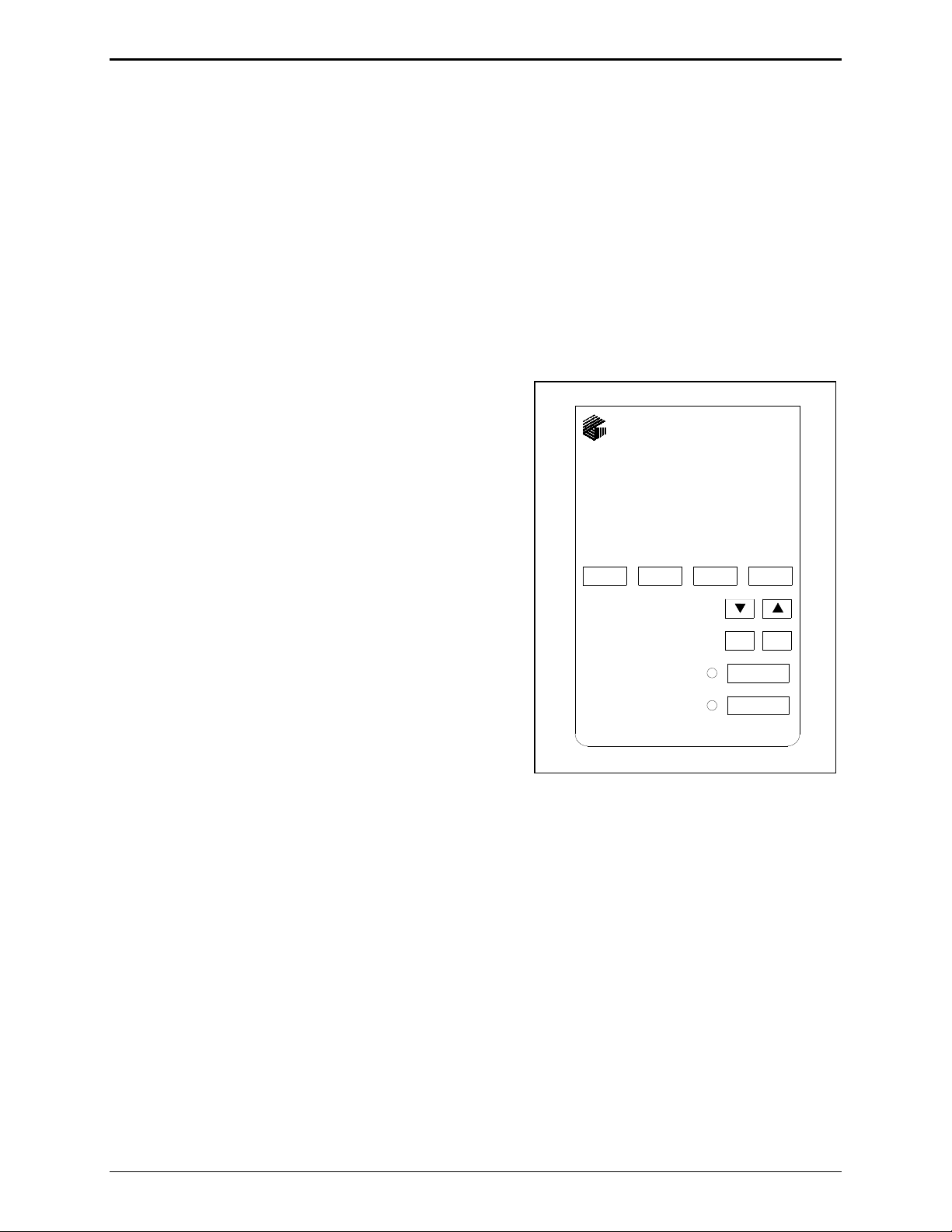
Desk Set Button Panel
Refer to the figure below for the locations of the buttons and LEDs on the desk set button panel.
Volume Buttons: The desk set includes two buttons
labeled
They increase and decrease the local speaker volume, mic
levels, and are used as programming function keys.
CTL: The CTL (Control) button is used in conjunction
with
speaker.
IC: The IC (Intercom) button allows communication
between desk set users without transmission over the
radio, and is used in programming functions.
VOLUME imprinted with up and down arrows.
VOLUME Up and VOLUME Down to control the local
F1 F2
ITR2000
TONE REMOTE
F3 F4
VOLUME
CTL IC
Monitor Button and LED: The MONITOR button is used to
place the radio in the monitor mode. The
MONITOR LED
illuminates while the unit is in the monitor mode, and it
MONITOR
TRANSMIT
flashes as indication when a parallel-connected device is
transmitting.
Monitor Button and LED: The red TRANSMIT button is
used to initiate voice transmissions by placing the desk set
in the transmit mode. The
TRANSMIT LED illuminates
Front View of the ITR2000A Desk Set
Button Panel
when transmitting, and it flashes as indication when a
parallel-connected device is transmitting.
F1, F2, F3, and F4 Programmable Buttons: The four buttons can each be programmed with one of 16
available function tones. Each button contains an internal red LED that lights to indicate that it is
currently selected. They are also used as indicator for the line output level and line-in sensitivity
adjustments.
02/12 4
Page 9
ITR1000A Tone Remote Desk Set Description
Internal Microphone and Speaker
The handset must be on-hook in order to use the internal microphone, which is intended for use in low
noise environments. The internal microphone and speaker are provided to allow hands-free
communication.
Handset
The desk set is equipped with a handset with a coil cord used for receiving and transmitting calls. The
handset includes a push-to-talk (PTT) pressbar.
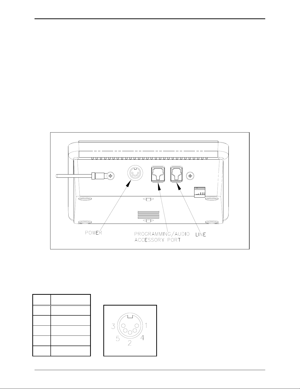
Connectors
The ITR2000A includes a five-pin 12 V dc nominal power connector, an eight-pin audio accessory
connector, and a modular phone line connector on the rear. The locations are shown in the figure below:
ITR2000A Desk Set – Rear View
Power Connector
The ITR2000A is powered by a listed ac wall transformer supplying nominal 12 V dc. The operating
range is 10.5 to 15 V dc. The five-pin power connector diagram and pinout are shown below:
Pin Function
1 -IN
2 Battery +IN
3 +IN
4 -IN
5 +IN
5 02/12
Page 10
Description ITR2000A Tone Remote Desk Set
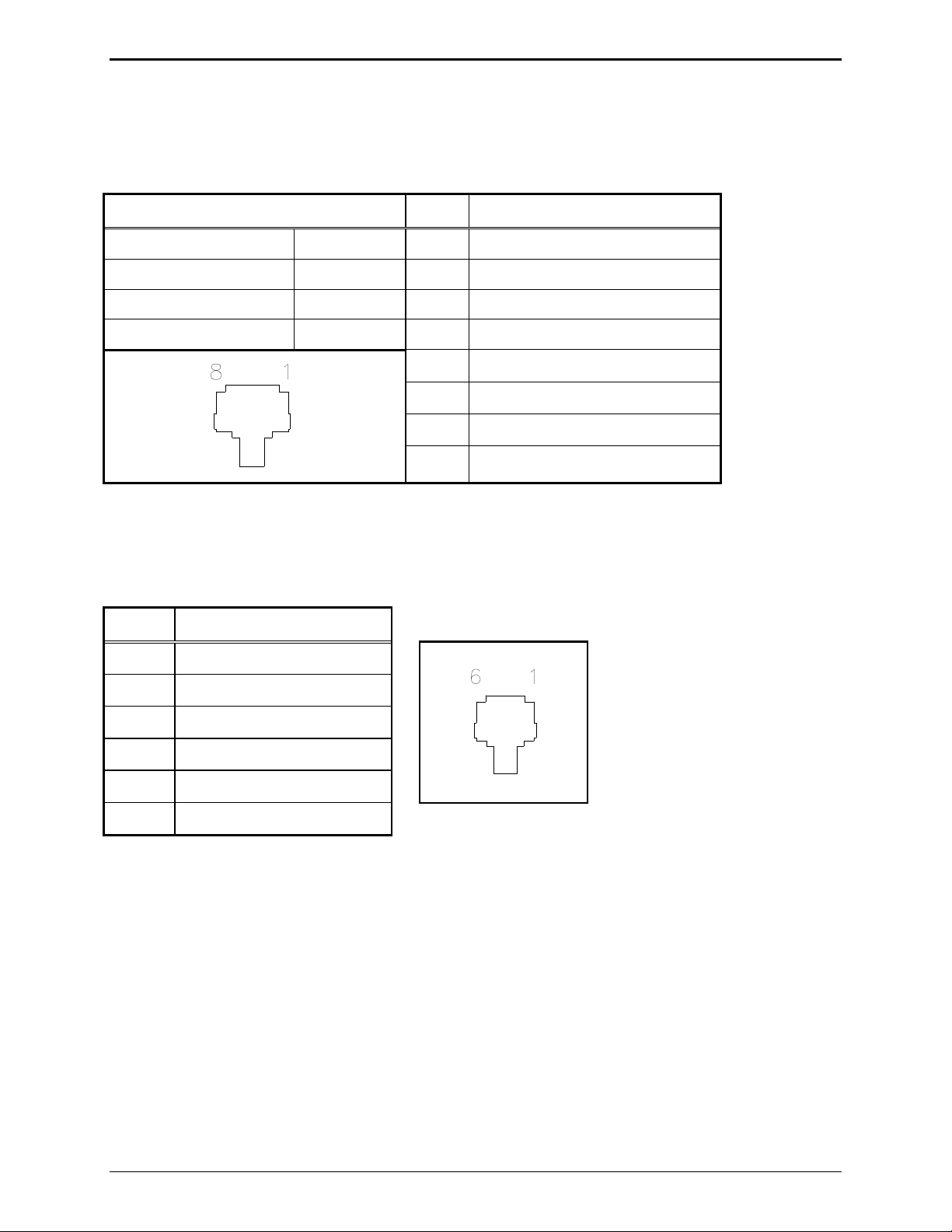
Audio Accessory/RS-232 Port (P411)
The ITR2000A contains an eight-pin modular desk mic port to provide audio accessory options. Possible
accessories include desk mic, gooseneck mic, boom mic, headset, or footswitch. The port is also used as
the connector to a PC for CARD Suite programming.
Mic Input Pin Function
Type: Passive input 1 B+ OUT (through 10 ohm)
Input Impedance: >2k ohm 2 RS-232 TX OUT
Nominal Input Level: −20 dBm 3 Monitor IN (closure to ground)
Input Adjustment Range: N/A 4 AGND
5 Mic IN (with bias voltage)
6 PTT IN (closure to ground)
7 RS-232 RX IN
8 RX audio OUT (handset audio)
Line Connector (P401)
The modular six-pin line connector is located on the rear of the desk set. See rear view diagram above.
The line connector pinout and diagram are shown below:
Pin Function
1
2 Four-wire RX +IN
3 Two-wire TX +OUT/RX IN
4 Two-wire TX –OUT/RX IN
5 Four-wire RX –IN
6
02/12 6
Page 11
ITR1000A Tone Remote Desk Set Description
Control Tones
Standard EIA tone keying tones are used for controlling the radio system. The sequence is:
A 2175 Hz High Level Guard Tone (HLGT) for 120 ms.
One of 16 function tones (FT) is sent for 40 ms.
FTs range from 2050 Hz to 550 Hz in 100 Hz steps. The FT level is 10 dB lower than the HLGT.
Monitor
FT1
FT2
FT3
2050
1950
1850
1750
FT4
FT5
FT6
FT7
1650
1550
1450
1350
FT8
FT9
FT10
FT11
1250
1150
1050
950
FT12
FT13
FT14
FT15
850
750
650
550
A 2175 Hz Low Level Guard Tone (LLGT) is generated for the duration of the transmission. The
LLGT is not generated during monitor. Because voice is present with this LLGT, a 2175 Hz filtering
is required in the tone panel.
When the monitor (CTCSS disable) is activated, the HLGT is generated for 120 ms, then a function tone
of 2050 Hz is generated for 40 ms.
Tone Levels
Assuming that the ITR2000A has the HLGT output level set to 0 dBm:
The FT level and audio voice level are –10 dBm (10 dB below HLGT)
The LLGT level is –30 dBm.
The HLGT and FT durations are programmable.
Some tone panels use the value of the FT frequency to provide certain radio control functions. If the
radio supports channel changes from an external logic source, the FT1 frequency of 1950 Hz could be
used to change the radio to channel 1. An FT6 frequency of 1450 Hz could change the radio to
channel 6.
Accessories
Description Part No.
GAI-Tronics Programming Bundle CD XAC4000A
Desk Microphone XDM004A
Footswitch (requires XAAB002A) XFS002A
Gooseneck Microphone XGM002A
Amplified Headset, Single Earpiece (requires coiled cord) XHS003C
Coiled Cord for XHS003C (requires XAAB002A) XCC004B
Coiled Cord with PTT for XHS003C (requires XAAB002A) XCC003C
Programming Cable XAC0004A
Audio Accessory Box XAAB002A
7 02/12
Page 12
Description ITR2000A Tone Remote Desk Set
Field Replacement Items
Description Part No.
PTT Handset with Cord, Black HANDSET-BLACK
Replacement Power Supply, 100–240 V ac/12 V dc 40419-008
Power Supply Adapter, European 40420-001
Power Supply Adapter, UK 40420-002
Power Supply Adapter, Australia 40420-003
Power Supply Adapter Korea 40420-004
Replacement Main PCBA 69296-003
Replacement Power Supply PCBA 69298-001
Replacement Speaker Assembly 61501-014
Performance Specifications
Color ..................................................................................................................................................... Black
Physical size .................................................................................................... 7.6 W 8.9 L 4.7 H inches
Weight ................................................................................................................................................ 2.4 lbs.
Temperature range .............................................................................................................. −35º C to +70º C
Humidity ...................................................................................................... 95% at 50º C (non-condensing)
Power input ............................................................................................ 10.5 to16 V dc; 400 mA maximum
Frequency response....................................................... +/−3 dB from 300 to 3000 Hz (except notch filter)
Hum and noise ................................................................................... Less than –45 dB below rated outputs
Audio output to speakers ................................................. 1 watt minimum with level in compression range
Audio distortion .............................................................................................................. Less than 3% THD
Maximum number of remotes ................................................................... As required by the system design
Microphone connections ................................................................................................... Eight-pin modular
Control functions (Tones standard as shipped)
Guard tone............................................................................................................... 2175 Hz, programmable
F1 to F4 tones ..................................... Each can be programmed from 550–2050 Hz in 100 Hz increments
Monitor ......................................................... 2050 Hz, programmable 550–2050 Hz in 100 Hz increments
02/12 8
Page 13

Operation
Introduction
The ITR2000A Tone Remote Desk Set provides radio system control from a remote location. The
ITR2000A control tones are sent to the remote adapter through a telephone line, and are used to control
radio functions such as transmit, channel change, and monitor.
Receive audio from the radio system is sent to the ITR2000A from the radio via the same telephone line
connection. The
These frequencies are dependent on your radio’s capabilities.
The ITR2000A is compatible with tone adapters that accept standard EIA tone keying sequences.
Front Panel Buttons
TRANSMIT Button and LED
F1, F2, F3, and F4 buttons allow selection of four different base station frequencies.
Press TRANSMIT to place the desk set in the transmit mode and initiate voice transmissions. The
TRANSMIT LED illuminates and the MONITOR LED extinguishes. See “Initiating Calls” section below.
TRANSMIT is also used in programming functions. See “Level Adjustments and Diagnostics” in the
“Installation” section of this manual.
MONITOR Button and LED
Press MONITOR to place the desk set, adapter, and the radio in the monitor mode (CTCSS/CDCSS
disable). The
MONITOR LED remains lit while in the unit is in the monitor mode. The ITR2000A
remains in the monitor mode until a call is initiated (PTT) or guard tone is detected on the line.
MONITOR is also used in programming functions. See “Level Adjustments and Diagnostics” in the
“Installation” section of this manual.
9 02/12
Page 14

Operation ITR2000A Tone Remote Desk Set
IC (Intercom) Button
Press IC to communicate between desk sets without transmitting over the radio. When IC is pressed and
held, microphone audio is routed to the line without activating the radio transmitter. Other tone remote
desk sets on the same line will hear the audio automatically.
IC button is also used in programming functions. See “Level Adjustments and Diagnostics” in the
The
“Installation” section of this manual.
CTL (Control) Button
CTL
is used in conjunction with VOLUME Up and Down to manually control the local speaker when the
handset is off-hook. Press and hold
VOLUME Up/Down Buttons
CTL, and then press VOLUME Up or VOLUME Down.
Local Speaker Volume:
Press
Press
VOLUME Up or VOLUME Down to adjust the local speaker volume if the handset is on-hook.
CTL + VOLUME Up to enable the local speaker while the handset is off-hook. When the
handset is placed back on-hook, the local speaker again operates normally– that is, it will be disabled
whenever the handset is taken off-hook.
Local Speaker Mute:
Press
Press
CTL + VOLUME Down to mute the local speaker.
VOLUME Up, VOLUME Down, or CTL + VOLUME Up to unmute the local speaker.
Handset Speaker Volume (with handset off-hook):
Press
VOLUME Up or VOLUME Down to adjust the handset speaker volume.
The volume control buttons are also used to adjust the sensitivity of the selected microphone, and in
programming functions. Refer to the “Microphone Sensitivity and Level Adjustments and Diagnostics”
in the “Installation” section for further instructions.
02/12 10
Page 15

ITR2000A Tone Remote Desk Set Operation
F1, F2, F3, and F4 Programmable Buttons
F1
, F2, F3, and F4 are programmable for specific function tones using the CARD Suite Software. Refer
to the “CARD Suite Software Programming” section for programming instructions.
Each time the ITR2000A is powered up, the status of the radio is unknown. The red LED flashes in the
programmable button last selected before the unit was powered down to provide indication of the
currently selected function tone. The flashing continues until the user or a parallel desk set transmits or
changes frequencies.
Each time guard tone is detected on the line, the ITR2000A assumes that the status of the radio is
unknown until a function tone is decoded at the proper time. Note that the programmable button LED
will remain flashing even if the user keys the
MONITOR button after power up. This is because the
monitor command does not control which frequency is being monitored, and the state of the radio is still
unknown.
Receiving Calls
When power is applied, the desk set is in the receive mode, allowing receive audio to be heard through
the speaker or handset. The desk set is always in receive mode unless the user presses
The desk set contains an internal or local speaker and a handset speaker, which operate as follows:
TRANSMIT or IC.
When the handset is in the cradle or on-hook, receive audio is heard on the local internal speaker.
When the handset is off-hook, receive audio is routed to the handset.
11 02/12
Page 16

Operation ITR2000A Tone Remote Desk Set
Initiating Calls
Before initiating a call, press MONITOR to verify that the radio channel is clear. To initiate a call, press
TRANSMIT or the handset push-to-talk (PTT) pressbar. The TRANSMIT LED illuminates when
transmitting.
Always allow a short delay before speaking to allow time for the radio channel to be established. The
TRANSMIT button or handset PTT bar must be held down while talking to the radio user and released to
listen. When the transmission is completed, the
the receive mode.
Handset Transmit
Using the handset is recommended when the desk set is located in noisy surroundings, or if full-duplex
2-wire operation is desired. Press the handset PTT bar or
microphone.
Transmit From Internal Microphone
Use the internal microphone only in low noise environments. The handset must be on-hook for the
internal microphone to operate. Press
TRANSMIT and speak in the direction of the internal microphone.
For the best transmit audio quality, maintain a distance of about 12 to 18 inches from the microphone.
TRANSMIT LED extinguishes and the desk set returns to
TRANSMIT button and speak into the handset
Transmit From Desk Microphone or Footswitch
The ITR2000A can be keyed to transmit with an external desk microphone, headset, or footswitch
through the audio accessory port. When a PTT is asserted through this port, the TX audio is originates
there. With the optional relay I/O module, it is possible to key the unit from virtually any logic closure
by using the input remap function of the module.
N
OTE: Some desk microphones operate as follows:
After pressing
MONITOR from the desk mic, the desk set front panel does not allow transmit until after
the desk mic transmit. It may be possible to change this by reversing the PTT and monitor polarity on the
accessory connector.
02/12 12
Page 17

ITR2000A Tone Remote Desk Set Operation
Scanning Operation
When used with the ITA2000S Scanning Adapter, the ITR2000A Tone Remote Desk Set provides
scanning functionality and display for up to four frequencies (channels). The scanning adapter rapidly
samples all four frequencies available to the ITR2000A Desk Set, searching for a carrier signal.
Detection of a carrier signal on a channel halts the scan and causes that channel’s associated frequency
button to illuminate.
N
OTE: The ITR2000A must be programmed for parallel status update operation with the CARD Suite
Programming Software.
Operation
Upon power-up, the scanning adapter automatically starts scan. While in scan mode, the adapter
channel-steers the radio at the configured scan rate. The
scan mode. Upon detection of carrier, the unit stops scan and generates the appropriate tone sequence to
the phone line and the
MONITOR button extinguishes. This tone sequence is decoded by the ITR2000A
Desk Set, the associated channel is selected, and the appropriate frequency button (
The desk set operator monitors receive and transmit on that frequency.
MONITOR button illuminates yellow, indicating
F1–F4) is illuminated.
The ITR2000A Desk Set
MONITOR button causes the adapter to start scanning if not in scan mode or stop scanning if in scan
mode. If the adapter is scanning and the
MONITOR button can be used as a manual scan on/off switch. Pressing the
MONITOR button is pressed, the adapter stops on the current
channel. The recommended operation is to allow the detected carrier signal to perform the stop scan
function automatically, using the
MONITOR button to resume scan after a conversation has been
completed.
While in scan mode, the Frequency buttons (
F1 – F4) are used to initiate a conversation or transmission.
An example of this operation is as follows:
1. While scanning, the ITR2000A Desk Set operator wishes to transmit on channel 3. Before doing so,
the operator must ensure that the channel is clear by placing the radio in monitor mode on channel 3.
To do this, the operator simply presses the
mode (do not press the
MONITOR button on the desk set).
F3 button, automatically placing the radio in monitor
2. The operator monitors the channel for activity and, upon assuring there is none, presses the
TRANSMIT key on the ITR2000A. The operator releases the TRANSMIT key on the ITR2000A Desk
Set and the adapter releases PTT from the radio. The operator carries on a normal conversation with
the field radio. If the operator wishes to again place the radio in monitor mode on channel 3, the
F3
key must be pressed again.
3. Upon loss of carrier, the unit resumes scan after an amount of time or until manually started by the
ITR2000A Desk Set (by pressing the
MONITOR button), depending on the configuration of the unit.
13 02/12
Page 18

Operation ITR2000A Tone Remote Desk Set
Parallel Status Operation
The ITR2000A supports parallel status updating. This feature allows the dispatch positions to know the
status of the base station. To decode this information, the unit senses high level guard tone (HLGT), then
decodes the function tone (FT2) following. Due to various tone control schemes supported by the unit, it
is important to understand the rules of decoding the function tones. They are as follows:
1. If the monitor function is decoded, the unit is placed into monitor mode. If any transmit function
tone is programmed the same as the monitor function tone, that transmit function tone will not be
decoded.
2. If two transmit function tones are programmed to the same frequency, only the first of the tones in
the sequence will be decoded; the subsequent transmit function tones set to the same frequency will
not.
3. If a PTT function tone is programmed, it is not decoded since this does not contain channel control
information. If a transmit function tone is programmed the same as the PTT function tone, the
transmit function tone will not be decoded.
To illustrate the priority of the decode, the following can be used:
Highest Priority
Monitor Function Tone
Supervisor ON Function Tone
Supervisor OFF Function Tone
PTT Function Tone
Transmit Function Tone (FT1 to FT16)
Lowest Priority
02/12 14
Page 19

Planning the Installation
Installation
Typical ITR2000A Installation
Mechanical Receipt Inspection
The ITR2000A Tone Remote Desk Set is shipped in a cardboard container with inserts. Thoroughly
inspect it as soon as possible after delivery. In-transit damage should be immediately reported to the
transportation company.
Mounting
The desk set can be placed on a desk or mounted vertically on a wall. However, some options may
prohibit wall mounting. To wall mount the desk set, remove the four bottom screws from the base and
then rotate the base 180. Reinstall the four screws to the base and rotate the handset hook located on the
front of the unit.
FCC Interference Warnings
The FCC requires that manuals pertaining to Class A and Class B computing devices contain warnings
about possible interference with local and residential radio and TV reception. Please read these warnings
and all safety information in the “Foreword” section of this manual.
15 02/12
Page 20

Installation ITR2000A Tone Remote Desk Set
Electrostatic Discharge (ESD) Protection
The ITR2000A has ESD protection circuitry that provides a high degree of protection against ESD, and
power and telephone line surges. The circuitry shunts the transient currents to earth ground through the
ground terminal. One of the two screws located on the back of the desk set can be used as an earth
ground terminal. See the rear view of the desk set for the ground screw terminal locations.
The ground terminal must be connected to a high quality earth ground point to obtain maximum
protection. Ideally, the ground point should originate at a 1/2-inch copper rod driven at least 6 feet into
the soil with a No. 16 AWG (or larger) copper wire run to the ground terminal taking the shortest path
possible. Where this is not possible, ground to a nearby water pipe or best available ground.
Equipment Required
Test Equipment
RF service monitor
AC voltmeter with dB ranges for measuring audio levels
Documentation
base station’s tone remote adapter manual
these installation instructions
Cable Installation Safety Considerations
Interconnecting, communications, and Class 2 dc power cables should be separated from electrical light
or other Class 1 circuits by at least 2 inches. The exception is where Class I wiring or power circuits are
run in a raceway, or are metal-sheathed or metal-clad, or are permanently separated from the conductors
of the other circuitry by a continuous and firmly fixed nonconductor such as porcelain tubes or flexible
tubing in addition to the insulation on the wire. Communications cables and in-building wiring should be
listed and marked for the purpose according to NEC Article 800.
Telephone Line Lightning and Over-Voltage Protection
The ITR2000A Tone Remote Desk Set has an over-current phone line fuse which protects against
occasional extreme fault conditions that may get past the primary protectors. An example of such a fault
condition is a power line cross. If the fuse requires replacement, use only with the same type fuse.
For maximum surge and lightning protection, building primary (over-voltage) protectors should be
installed at the point where the telephone lines enter the radio equipment building. Primary protectors
are usually required by local codes and should be provided by your leased line provider.
Power Connection
Connect the ITR2000A to the listed ac wall transformer, which supplies nominal 12 V dc. Optionally,
the desk set can be powered by other dc sources. The operating range is 10.5 to 16 V dc. Refer to the
power connection pinout on page 5 of the “Description” section.
02/12 16
Page 21

ITR2000A Tone Remote Desk Set Installation
Line Connection
Connect the telephone line to the modular connector located on the back of the desk set. Refer to the
pinout on page 6 in the “Description” section. The six-pin modular jack is a full/half duplex connection
to the line. The CARD Suite Programming Software allows selection of a four-wire type of connection
to the line. In the two-wire mode, the hybrid will be auto-balancing. An average of ten desk sets can be
connected in parallel, depending on the system design. The maximum loss between any two desk sets or
between a desk set and the station should not exceed 20 dB. Desk sets are shipped with line terminations
active. With parallel units connected, only the farthest desk set units should be terminated. Observe
right to left pinout for pins 1 through 6.
Line Considerations - Private Circuit
If leased lines from your local telephone company are used between the ITR2000A and the ITA2000A or
similar tone remote adapter, the telephone company (Local Exchange Carrier) may request a Facility
Interface Code (FIC). The FIC is subject is to local availability.
Analog Facility Interface Code
FIC Description
02N02 Two-wire private line; no signaling conversion by LEC (IN-Band)
02N04 Four-wire private line; no signaling conversion by LEC (IN-Band)
Metallic Two- or four-wire metallic private line (tip, ring, and sleeve circuits)
Within a manufacturing plant, a campus, or large building, customer-supplied metallic pairs may be used.
Metallic pairs must be used if the dc control option is installed. It is not necessary to have dc continuity
on these lines.
Circuit Conditioning
The desk set is designed to work with good-quality analog speech band or leased private circuit. This
was previously known as ‘basic’ conditioning under Series 2000/3002 service.
The line must be non-PSTN (no dial tone, talk-battery, or signaling).
Less than 20 dB line loss should exist from the ITR2000A to the tone panel.
This equipment falls under the Category II, FCC Tariff #260 Service and is exempt from FCC Part 68
registration. (Ref. FCC Form 730 Application Guide pages 1–5.) For two-wire operation, 2000 Series
lines may be used with or without conditioning. C1 or C2 conditioning is available for these lines and
relates to the envelope delay distortion and attenuation. A basic conditioned line may be used if it is the
only type available. Overall system quality is limited by the quality of these lines.
Audio Accessory/RS-232 Port Connection
Use the eight-pin audio accessory/RS-232 port to connect a PC to the ITR2000A with the proper
connecting cable in order to use the CARD Suite Programming software. See the “CARD Suite
Programming Software” section of this manual for instructions on set up.
After programming is complete, connect an audio accessory, such as a desk microphone, gooseneck
microphone, boom microphone, headset, or footswitch, if desired. The microphone input type is passive,
with an input impedance of greater than 2k ohms and a nominal input level of −20 dBm. Refer to the
audio accessory/RS-232 port pinout on page 6 in the “Description” section.
17 02/12
Page 22

Installation ITR2000A Tone Remote Desk Set
Microphone Sensitivity
After connections have been made, the ITR2000A must be configured for transmit and receive audio
levels. These adjustments are made using the front panel buttons. The microphone sensitivity
adjustment is used to compensate for different user voice levels and varied acoustical conditions. Refer
to the following instructions to adjust the different microphones.
Internal Microphone
1. Place the handset in the cradle.
2. While holding down
IC button, momentarily press VOLUME Up button.
A single beep is heard to indicate that the microphone sensitivity level can be adjusted.
No audible beep indicates the microphone sensitivity adjustment function is already enabled.
3. Press and hold
TRANSMIT, speak into the internal microphone, and press VOLUME Up or VOLUME
Down to increase sensitivity or decrease microphone sensitivity.
N
OTE: The display shows the relative TX level as a number between 1 and 5. To confirm the
absolute level, measure the transmit level across the TX line pair using an ac millivolt meter or dBm
meter.
4. After the adjustment has been made, press and hold the
VOLUME Down button.
IC button, and momentarily press the
A single beep is heard to indicate the microphone adjustment has been saved and the adjustment
function had been closed. No audible beep indicates the microphone adjustment function has already
been closed.
Handset Microphone
1. With the handset off-hook, hold down the IC button and momentarily press the VOLUME Up button.
A single beep is heard in the earpiece to indicate that the microphone sensitivity level can be
adjusted. No audible beep indicates the microphone sensitivity adjustment is already enabled.
2. To adjust the sensitivity level, press the handset PTT button, speak into the handset microphone, and
press
VOLUME Up or VOLUME Down to increase or decrease the sensitivity level.
3. After adjustment has been made, hold down the
IC button and momentarily press the VOLUME Down
button.
A single beep is heard to indicate the microphone setting has been saved, and the adjustment function
has been closed. No audible beep indicates the microphone adjustment has already been closed.
Accessory Microphone
1. With the handset on-hook, hold down the IC button and momentarily press the VOLUME Up button.
A single beep is heard to indicate that the microphone sensitivity level can be adjusted. No audible
beep indicates the microphone sensitivity adjustment function is already enabled.
2. To adjust the sensitivity level, press the accessory microphone PTT/
accessory microphone, and press the
VOLUME Up or VOLUME Down to increase or decrease the
TRANSMIT button, speak into the
sensitivity level.
3. After the adjustment has been made, hold down the
IC button and momentarily press the VOLUME
Down button. A single beep is heard to indicate the microphone setting has been saved, and the
adjustment function has been closed. No audible beep indicates the microphone adjustment function
has already been closed.
02/12 18
Page 23

ITR2000A Tone Remote Desk Set Installation
Level Adjustments and Diagnostics
After connections have been made, the desk set must be configured for transmit and receive audio levels.
These adjustments are made using the front panel buttons.
F1, F2, F3, and F4 are used to program the ITR2000A for specific installations and perform diagnostics.
They are:
Line Output Adjust
Line-In Sensitivity
Diagnostics
Desk sets are shipped from the factory with default settings that meet most installation requirements.
The default settings are:
–10 dBm for Line Output Level Adjustment
–9 dBm for Line-in Compensation
However, it is important to verify that these parameters are adjusted to meet your specific installation
needs. The tree diagram below illustrates which buttons to press to access the programming features.
F1 or F2 or F3 or F4
Press:
Press: To program:
F1
- Line Output Adjust
F2
- Line-in Sensitivity
F3
- Internal Diagnostics
Press: To program:
F1
- Not supported
F2
- Not supported
F3
- RS-232 Diagnostic
F4
- Not supported
Main Programming Selection Mode
Enter the main programming selection mode as follows:
1. Remove power to the ITR2000A.
2. Reapply power while holding down one of the programmable buttons, F1, F2, F3, or F4.
3. The F1, F2 and F3 LEDs flash, indicating the programming mode is activated and which buttons are
active. Release the programmable button.
19 02/12
Page 24

Installation ITR2000A Tone Remote Desk Set
F1 – Line Output Adjust (Transmit)
Connect an ac voltmeter or SinAd meter across the line to achieve the proper level setting. Ensure that
the line is terminated with a 600-ohm load.
After entering the main programming selection mode, press the
N
OTE: The level is factory set at –10 dBm. The range for this setting is –10 dBm to +12 dBm.
After pressing the
setting. As the setting is changed, the
F1 button, the F1 through F4 LEDs light to indicate the current line output level
F1 through F4 LEDs indicate the new value. The desk set buttons
F1 button to adjust the line output level.
perform the following functions when in the Line Output Adjust mode:
Button
VOLUME Up Increases the output level, verifying the proper level with the meter connected to the
Function
line.
VOLUME
Down
TRANSMIT
MONITOR
IC
(INTERCOM)
Decreases the output level, verifying the proper level with the meter connected to the
line.
Saves the current setting and exits back to the main selection mode.
Restores the previously programmed setting.
Exits the Line Output Adjustment mode without saving the selection, but maintains
the current setting until power is cycled. This is useful for experimenting with
different settings.
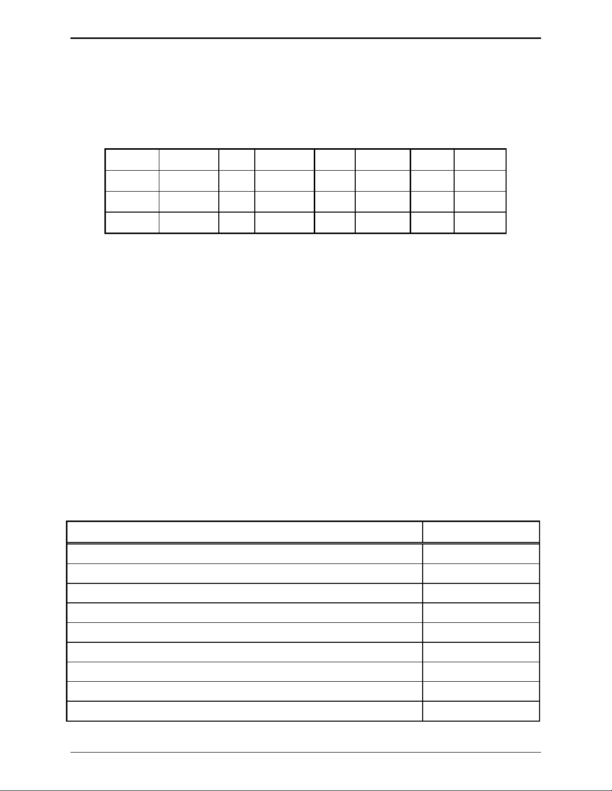
Refer to the Line Output Level table below for the LED lighting pattern that indicates the levels.
Level
1
2
3
4
5
6
7
8
9
10
11
Line Output (TX) Level Adjustment
F1 LED
is:
F2 LED
is:
F3 LED
is:
F4 LED
is:
Line Level
(600 Ohm)
OFF OFF OFF OFF −10 dB
(factory default)
OFF OFF OFF ON −8 dB
OFF OFF ON OFF −6 dB
OFF OFF ON ON −4 dB
OFF ON OFF OFF −2 dB
OFF ON OFF ON 0 dB
OFF ON ON OFF +2 dB
OFF ON ON ON +4 dB
ON OFF OFF OFF +6 dB
ON OFF OFF ON +8 dB
ON OFF ON OFF +10 dB
12
ON OFF ON ON +12 dB
02/12 20
Page 25

ITR2000A Tone Remote Desk Set Installation
F2 – Line-in Sensitivity (Receive)
After entering the main programming selection mode, press F2 to adjust the line-in sensitivity. This
adjustment allows the desk set to compensate for a range of 0 to 15 dB of line loss in 3 dB increments.
The compensation is considered a pre-gain to the line-in circuitry of the desk set.
For example, if the RX audio output of the radio tone panel or ITA2000A is –10 dBm and the phone
system has 10 dB of line loss, the ITR2000A line-in sensitivity should be set to level 4 (−9 dBm) to
accommodate the 10 dB of incurred line loss.
After pressing
As the setting is changed, the
F2, the F1 through F4 LEDs light to indicate the current line-in sensitivity level setting.
F1 through F4 LEDs indicate the new value. The desk set buttons provide
the following functions when used in the Line-in Sensitivity mode:
Button
VOLUME Up Increases the line-in sensitivity or reduces the pre-gain for the line input.
VOLUME DOWN
TRANSMIT
MONITOR
IC
Function
Decreases the line-in sensitivity or increases the pre-gain for the line input.
Saves the current setting and exits back to the main selection mode.
Restores the previously programmed setting.
Exits the Line-in Sensitivity Adjustment mode without saving the selection, but
maintains the current setting until power is cycled. This is useful for experimenting
with different settings.
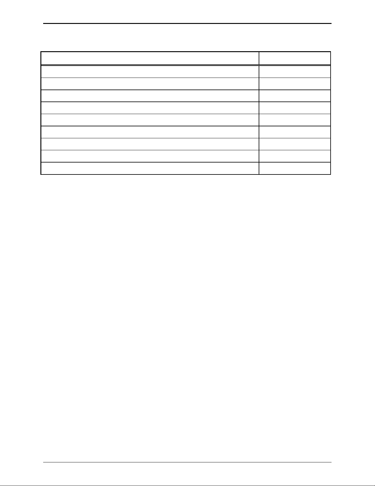
Refer to the Line-in Compensation table below for an explanation of how the LED lighting pattern
indicates the levels.
Line-in (RX) Compensation
Level
1
2
3
4
F1 LED
is:
F2 LED
is:
F3 LED
is:
F4 LED
is:
Line-in
Compensation
OFF OFF OFF OFF 0 dBm
OFF OFF OFF ON −3 dBm
OFF OFF ON OFF −6 dBm
OFF OFF ON ON −9 dBm
(factory default)
5
6
OFF ON OFF OFF −12 dBm
OFF ON OFF On −15 dBm
21 02/12
Page 26

Installation ITR2000A Tone Remote Desk Set
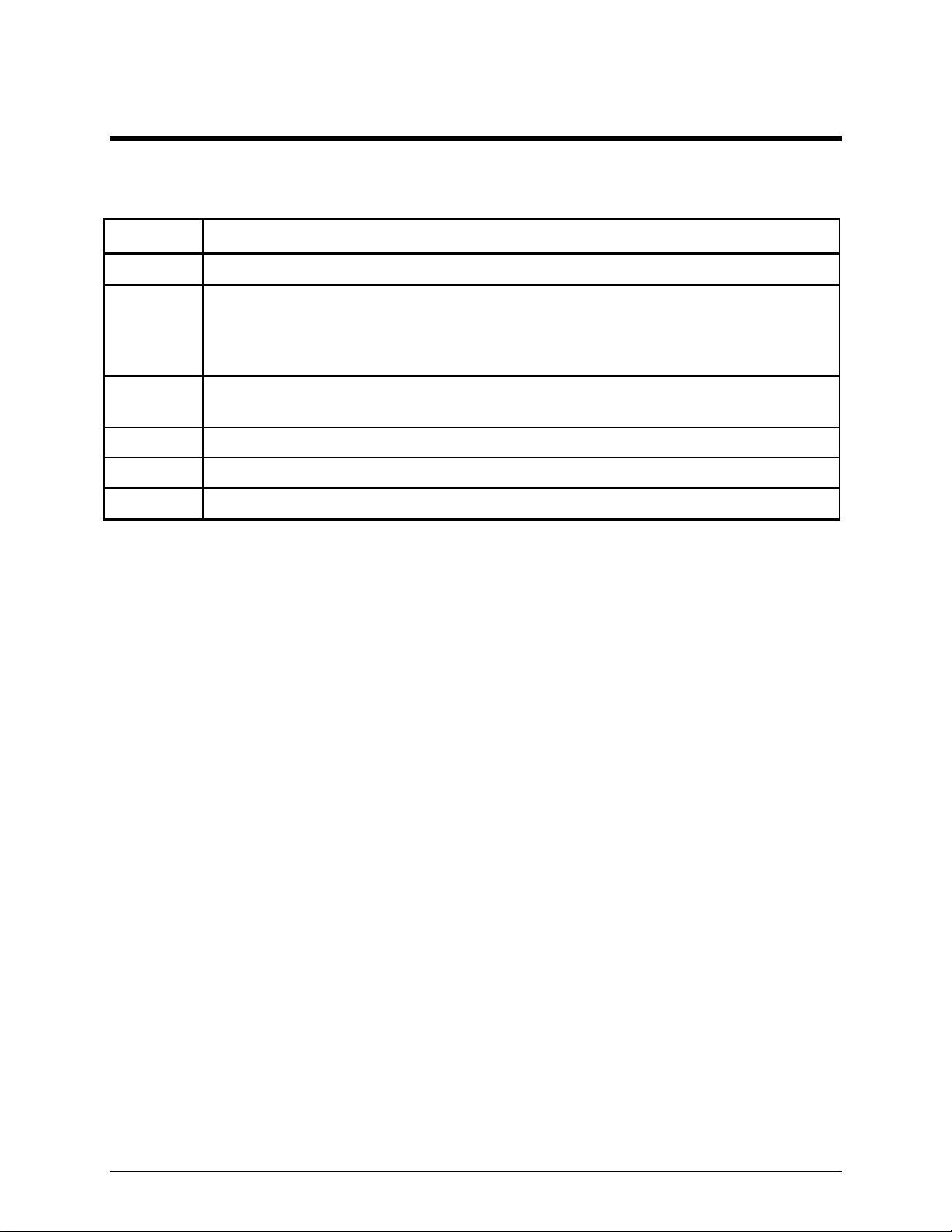
F3 – Internal Diagnostics
After pressing F3 to enter the internal diagnostics mode, all the programmable button LEDs flash. Use
TRANSMIT to return to the main programming selection mode.
Button Function
F1
F2
F3
Not supported in the ITR2000A.
Not supported in the ITR2000A.
RS-232 diagnostic: This diagnostic tests the RS-232 using a loop-back test. When
entered,
F1 through F4 LEDs are off.
Short TXD P411-2 to RXD P411-7.
If the RS-232 port is working, the
F1 through F4 LEDs count as long as the short is
present.
Removing the short stops the count.
Reconnecting the short continues the count.
It is important to measure the actual level of the TXD signal to ensure full positive and
F4
TRANSMIT
negative swing. Use
Not supported in the ITR2000A.
Returns the ITR2000A to the main programming selection mode.
TRANSMIT to return to the internal diagnostic selection mode.
To quickly reset the desk set to default levels:
Enter the main programming selection mode and while depressing the
CTL button, press the VOLUME Up
button. Wait for all LEDs to flash continuously (approximately 2 seconds), then press the
button.
TRANSMIT
02/12 22
Page 27

CARD Suite Programming Software
General Description
GAI-Tronics’ CARD Suite Programming Software, included in the No. XAC4000A Programming
Bundle CD, is needed to program some of the functions and parameter settings of the dispatch
equipment. It allows entry of operational programming data into your personal computer for transfer to
the equipment. The programmed data can be retrieved, edited, archived, and printed in hard copy for
record keeping. Detailed programming information can be found in CARD Suite’s Help file. The
following information is provides as guidance to initiate the programming application.
Connection
The GAI-Tronics equipment must be connected to your personal computer with the programming cable,
Part No. XAC0004A, before the programming software can be used. To make this connection, attach the
cable to the COM1 or COM2 connector on the computer. Connect the other end to the programming jack
on the GAI-Tronics equipment.
Installation
The minimum system requirement necessary to support the CARD Suite Software Application is
Windows 95 or newer. However, CARD Suite is not compatible with Windows NT. It is compatible
with Windows XP (Home or Professional), Vista, and Windows 7 when used in Virtual Mode.
The CARD Suite Programming Application components are contained on CD-ROM. Please exit all
other programs that are running until the installation is complete.
1. Place the CD in the PC’s CD-ROM drive. If the “auto-run” feature on your CD-ROM drive is
enabled, a program selection chart will be displayed. Select Card Suite for downloading. If for any
reason the installation does not start up automatically, it can be run from the Start menu.
Select the
x:\Setup.exe where x represents the drive letter that is associated with your CD-ROM drive. A
CARD Suite icon should appear on the desktop display after successful installation.
2. After opening the program, select the appropriate product icon, click on File in the toolbar and select
New Archive to begin creating an archive.
3. Enter an archive description (name) and customer/site (name), select the method of creating the
archive (default values or reading a connected unit), and click Ok button to create the archive.
4. View the Help file for programming guidance.
START button and then select Run from the Start menu. At the prompt, type
23 02/12
Page 28

CARD Suite Software ITR2000A Tone Remote Desk Set
02/12 24
Page 29

T roubleshooting
Troubleshooting the ITR2000A Desk Set
The following is a list of potential problems you may encounter and possible solutions.
Problem Possible Solution
Refer to these solutions in
addition to the ones
suggested for the problems
below.
Ensure that the telephone line is balanced by making sure neither side of the
The ITR2000A will not
cause the tone remote
adapter to key the radio.
Ensure that the ITR2000A output level is set properly. The high level guard
Low or distorted RX audio Ensure that the tone remote adapter is interfaced correctly to the radio
Verify that there is a valid telephone line path from the ITR2000A to the
tone remote adapter.
telephone line is grounded.
Ensure that the proper tone adapter function tone for keying the radio is
programmed into the ITR2000A. Refer to the tone remote adapter user
manual for valid function tones that will key the radio.
tone should be set in a range of 0 dBm to –10 dBm into the telephone line.
Assuming no more that 20 dB of line loss on the telephone line, this level
should be adequate for the tone adapter to decode the tone sequence.
system. The quality of the audio signal output depends on the tone remote
adapter.
1. Use an RF service monitor modulated by a 1000 Hz tone at 60% of rated
system deviation at the receive frequency and CTCSS/CDCSS (if
necessary). Measure and note the level of the 1000 Hz tone across the
ITR2000A telephone line.
2. Remove the 1000 Hz tone and set the ITR2000A receive level according
to the table shown on page 21. If an RF service monitor is not available,
use a portable or mobile radio.
3. Transmit to the station and measure the nominal voice audio on the
ITR2000A telephone line.
4. Set the ITR2000A receive level to the nearest level that was measured
according to the tables on page 21.
Unsquelched noise in RX
audio.
No RX audio. Ensure that the tone remote adapter is supplying receive audio onto the
Ensure that the ITR2000A desk set local speaker is not muted.
25 02/12
The tone adapter must be connected to a muted and de-emphasized receive
point in the radio. If connected directly to a detector or discriminator
output, continuous noise is heard unless the tone panel has a squelch circuit
to mute the receive radio.
telephone line.
Page 30

Troubleshooting ITR2000A Tone Remote Desk Set
Problem Possible Solution
Low TX audio. Verify that the ITR2000A TX output level is properly set and ensure that
there is no more than 20 dB of loss in the telephone line, which can cause
degradation of the audio signal.
Verify that the microphone sensitivity is set properly:
1. Using an RF service monitor set to the transmit frequency of the radio,
transmit from the ITR2000A and speak into the handset. Note the
transmit deviation level.
2. Refer to the “Microphone Sensitivity” section and adjust the handset
transmit level output up or down for the desired modulation level.
Refer to page 18. It may be necessary to adjust the transmit audio
output on the tone remote adapter at the station.
Distorted TX audio. Verify that the tone remote adapter’s transmit audio output level is not set
too high for the station’s rated input level. Refer to the station and tone
remote adapter manuals for proper setting and adjustment procedures.
Verify that the microphone sensitivity is set properly. Use an RF service
monitor set to the station transmit frequency. Transmit from the ITR2000A
and speak into the handset. Note the transmit level. Refer to the
“Microphone Sensitivity” section and adjust the handset transmit level
output up or down for the desired deviation. Refer to the “Line Output
Adjustment Level” table on page 20 of the “Installation” section for nominal
transmit output levels, and follow the “Adjustments and Diagnostics”
information to set the transmit output level for the internal microphone.
ITR2000A does not
transmit or receive.
Ensure that the ITR2000A is connected to an ac or dc (if using a dc power
supply option) power source.
Check for a blown fuse.
No audio on local speaker Ensure that the volume is not turned down all the way, and the handset is
on-hook. If receive audio is not switched to the local speaker when the
handset is on-hook, the handset may be defective.
Ensure the local speaker is not muted.
Parallel status updating is
not working properly.
Ensure that the F1 through the F4 buttons on parallel ITR2000As are
programmed identically for the same function tone settings. If the
ITR2000A decodes a function tone not programmed into one of four
buttons, the F1 button LED flashes to indicate an unknown function decode.
Fuse Replacement
CAUTION
For continued safe operation, replace fuses with the same type:
F401 is a Bussman GMA 1 amp FB fuse.
02/12 26
Page 31

Circuit Boards
27 02/12
Page 32

Circuit Boards ITR2000A Tone Remote Desk Set
28
Page 33

ITR2000A Tone Remote Desk Set Circuit Boards
29
Page 34

Circuit Boards ITR2000A Tone Remote Desk Set
30
Page 35

Schematics
31 02/12
Page 36

Schematics ITR2000A Tone Remote Desk Set
Line Interface Schematic - Sheet 1
32
Page 37

ITR2000A Tone Remote Desk Set Schematics
User Audio I/O Schematic Diagram - Sheet 2
33
Page 38

Schematics ITR2000A Tone Remote Desk Set
Control Microprocessor I/O Schematic Diagram - Sheet 3
34
Page 39

ITR2000A Tone Remote Desk Set Schematics
DSP Block Schematic Diagram - Sheet 4
35
Page 40

Schematics ITR2000A Tone Remote Desk Set
Tone Keypanel Schematic Diagram - Sheet 5
36
Page 41

ITR2000A Tone Remote Desk Set Schematics
Power Supply Schematic Diagram - Sheet 6
37
Page 42

Schematics ITR2000A Tone Remote Desk Set
Signaling Section Schematic Diagram - Sheet 7
38
Page 43
Term Definition
Definitions and Acronyms
CSQ
CTCSS
CDCSS
HLGT
LLGT
PTT
Carrier squelch
A means of grouping users of a common radio channel. Subaudible tones are transmitted
with audio; a particular radio’s speaker (or the speakers of a group of radios) will unmute
to broadcast a transmission only if the associated subaudible tone identifies it as
belonging to the radio’s user group.
A system analogous to CTCSS but using low speed digital signaling instead of subaudible
tones.
High level guard tone
Low level guard tone
Push-to-talk
39 02/12
Page 44

Notes: ITR2000A Tone Remote Desk Set
40
 Loading...