

GAI-Tronics ITR1000A User And Installation Manual
Pub. 43004-002B
GAI-TRONICS® CORPORATION
A HUBBELL COMPANY
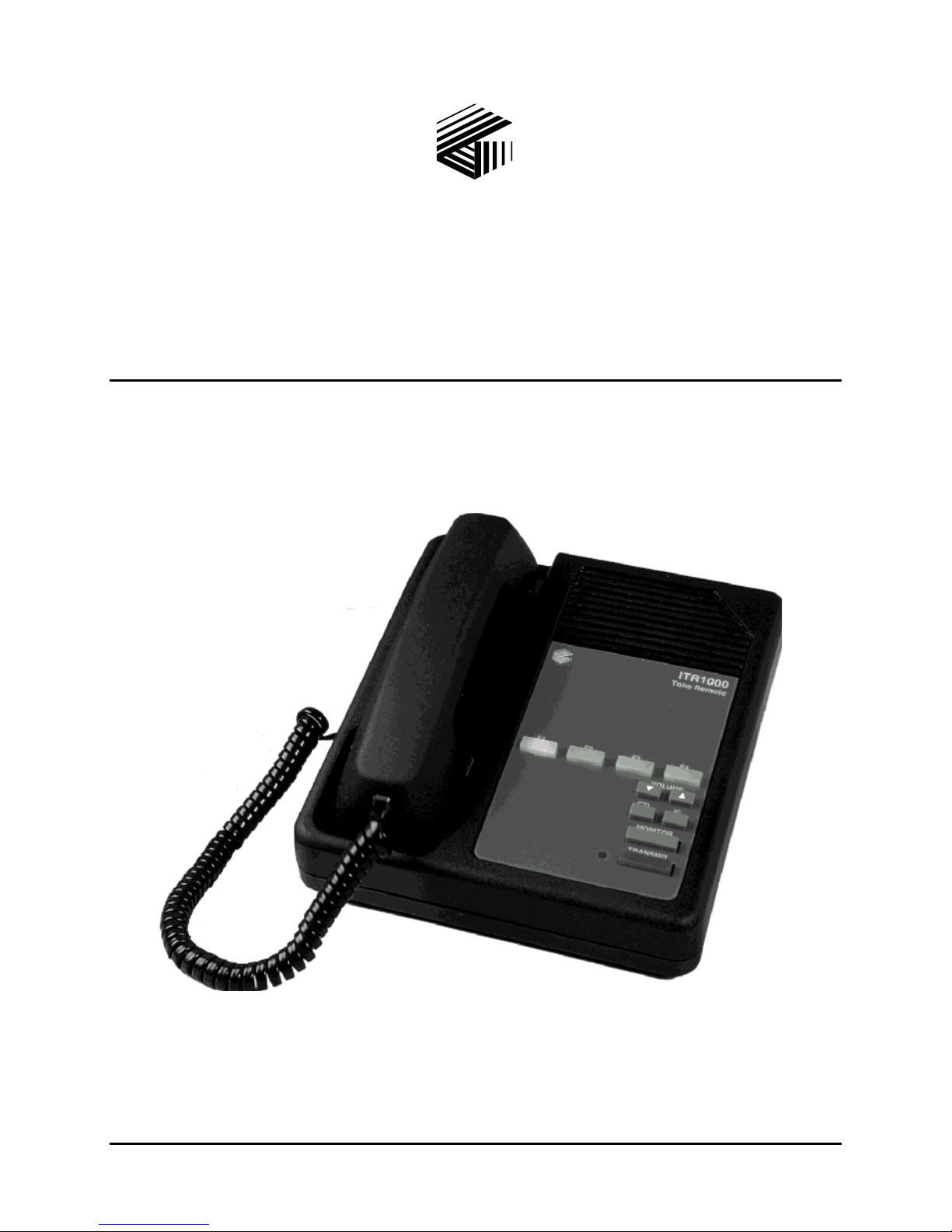
ITR1000A Basic Tone Remote Desk Set
User and Installation Manual
GAI-Tronics Corporation P.O. Box 1060, Reading, PA 19607-1060 USA
610-777-1374 800-492-1212 Fax: 610-796-5954
V
ISIT WWW.GAI-TRONICS.COM FOR PRODUCT LITERATURE AND MANUALS

CONFIDENTIALITY NOTICE
This manual is provided solely as an operational, installation, and maintenance guide and contains
sensitive business and technical information that is confidential and proprietary to GAI-Tronics.
GAI-Tronics retains all intellectual property and other rights in or to the information contained herein,
and such information may only be used in connection with the operation of your GAI-Tronics product or
system. This manual may not be disclosed in any form, in whole or in part, directly or indirectly, to any
third party.
COMPUTER SOFTWARE COPYRIGHTS
This product contains copyrighted computer programs stored in semiconductor memory. These programs
are copyrighted by GAI-Tronics Corporation and may not be reproduced in any form without express
written permission from GAI-Tronics.
WARRANTY
GAI-Tronics warrants for a period of one (1) year from the date of shipment, that any GAI-Tronics equipment supplied
hereunder shall be free of defects in material and workmanship, shall comply with the then-current product specifications and
product literature, and if applicable, shall be fit for the purpose specified in the agreed-upon quotation or proposal document. If
(a) Seller’s goods prove to be defective in workmanship and/or material under normal and proper usage, or unfit for the purpose
specified and agreed upon, and (b) Buyer’s claim is made within the warranty period set forth above, Buyer may return such
goods to GAI-Tronics’ nearest depot repair facility, freight prepaid, at which time they will be repaired or replaced, at Seller’s
option, without charge to Buyer. Repair or replacement shall be Buyer’s sole and exclusive remedy, and the warranty period on
any repaired or replacement equipment shall be one (1) year from the date the original equipment was shipped. In no event shall
GAI-Tronics’ warranty obligations with respect to equipment exceed 100% of the total cost of the equipment supplied hereunder.
The applicability of any such third-party warranty will be determined solely by GAI-Tronics.
Services. Any services GAI-Tronics provides hereunder, whether directly or through subcontractors, shall be performed in
accordance with the standard of care with which such services are normally provided in the industry. If the services fail to meet
the applicable industry standard, GAI-Tronics will, for a period of one (1) year from the date of completion, re-perform such
services at no cost to the Buyer. Re-performance of services shall be Buyer’s sole and exclusive remedy, and in no event shall
GAI-Tronics’ warranty obligations with respect to services exceed 100% of the total cost of services provided hereunder.
Limitations/Exclusions. The warranty on any equipment supplied hereunder is subject to Customer’s use in compliance
with applicable FCC regulations and manufacturer specifications. The warranties herein shall not apply to, and GAI-Tronics
shall not be responsible for, any damage to the goods or failure of the services supplied hereunder, to the extent caused by
accident, misuse, abuse, neglect, system design, product modification, failure to follow instructions contained in the product
manual, repair, or attempted repair by anyone not authorized by GAI-Tronics, improper installation, installation of parts that do
not conform to the quality or specifications of the original parts or accessories, damage or loss occurred during shipment, or any
unit which is not new when sold or upon which the serial number has been defaced, modified or removed. The warranty does
not extend to damage incurred by natural causes including Force Majeure. The warranty does not cover microprocessors if
failure is due to static damage or application of improper voltage.
THE WARRANTIES AND REMEDIES CONTAINED
HEREIN ARE IN LIEU OF AND EXCLUDE ALL OTHER WARRANTIES AND REMEDIES, WHETHER
EXPRESS OR IMPLIED BY OPERATION OF LAW OR OTHERWISE, INCLUDING ANY WARRANTIES OF
MERCHANTABILITY OR FITNESS FOR A PARTICULAR PURPOSE.
Operational and Maintenance Procedures. Buyer acknowledges that any improper use, maintenance, or
modification of the equipment provided hereunder, or use of unqualified maintenance or service technicians will severely impair
the operational effectiveness of the entire communication system. Buyer hereby agrees to indemnify, defend and hold GAITronics harmless from and against any and all third party claims arising, in any manner, out of: (a) Buyer’s neglect of the
equipment; (b) Buyer’s use of technicians not authorized by GAI-Tronics to service the equipment; or (c) Buyer’s improper use
or modification of the equipment or failure to follow the operational and maintenance procedures provided with the equipment.
Limitation of Liability/Damages. In no event (even should circumstances cause the exclusive warranties and remedies
set forth in the Warranty section to fail of their essential purpose) shall either party be liable for any indirect, incidental, special
or consequential damages (including, but not limited to, loss of use, loss of anticipated profits, or damages arising from delay)
whether such claims are alleged to have arisen out of breach of warranty, breach of contract, strict or absolute liability in tort, or
other act, error or omission, or from any other cause whatsoever, or any combination of the foregoing.
01/05 Publication 43004-002B i

Table of Contents
FOREWORD...............................................................................................................................................................1
COPE OF MANUAL ....................................................................................................................................................1
S
OMENCLATURE........................................................................................................................................................1
N
RDERING REPLACEMENT PARTS ..............................................................................................................................1
O
ERVICE AND REPAIR.................................................................................................................................................1
S
NTERFERENCE WARNING..................................................................................................................................1
FCC I
AFE HANDLING OF CMOS INTEGRATED CIRCUIT DEVICES .....................................................................................2
S
DESCRIPTION ...........................................................................................................................................................3
F
EATURES AND BENEFITS OF THE ITR1000A BASIC TONE REMOTE DESK SET .........................................................3
HYSICAL DESCRIPTION............................................................................................................................................. 4
P
ESK SET BUTTON PANEL .........................................................................................................................................4
D
F1, F2, F3, and F4 Frequency Buttons ................................................................................................................4
Volume Buttons.....................................................................................................................................................4
Control Button......................................................................................................................................................5
Intercom Button....................................................................................................................................................5
Monitor Button......................................................................................................................................................5
Transmit Button....................................................................................................................................................5
Transmit LED .......................................................................................................................................................5
NTERNAL MICROPHONE ............................................................................................................................................5
I
ANDSET ...................................................................................................................................................................5
H
ROGRAMMING SWITCHES.........................................................................................................................................6
P
SWA Switch Settings Table...................................................................................................................................6
ITR1000A B
ITR1000A B
ERFORMANCE SPECIFICATIONS ................................................................................................................................8
P
ASIC TONE REMOTE DESK SET ACCESSORIES .......................................................................................7
ASIC TONE REMOTE DESK SET FIELD REPLACEMENT ITEMS.................................................................7
OPERATION...............................................................................................................................................................9
O
PERATIONAL DESCRIPTION......................................................................................................................................9
RONT PANEL BUTTON OPERATION...........................................................................................................................9
F
F1, F2, F3, and F4 Frequency Buttons ................................................................................................................9
VOLUME Up/Down Buttons ................................................................................................................................9
CONTROL Button.................................................................................................................................................9
IC (Intercom) Button.............................................................................................................................................9
MONITOR Button.................................................................................................................................................9
TRANSMIT Button................................................................................................................................................9
NITIATING CALLS....................................................................................................................................................10
I
ECEIVING CALLS....................................................................................................................................................10
R
ANDSET TRANSMIT................................................................................................................................................10
H
RANSMIT FROM INTERNAL MICROPHONE ..............................................................................................................10
T
INSTALLATION ......................................................................................................................................................11
P
LANNING THE INSTALLATION.................................................................................................................................11
ECHANICAL RECEIPT INSPECTION .........................................................................................................................11
M
OUNTING...............................................................................................................................................................11
M
NTERFERENCE WARNINGS..............................................................................................................................11
FCC I
QUIPMENT REQUIRED.............................................................................................................................................12
E
ABLE INSTALLATION SAFETY CONSIDERATIONS....................................................................................................12
C
ELEPHONE LINE LIGHTNING AND OVER-VOLTAGE PROTECTION............................................................................12
T
OWER CONNECTIONS .............................................................................................................................................12
P
INE CONNECTIONS .................................................................................................................................................12
L
01/05 Publication 43004-002B ii

Table of Contents ITR1000A Basic Tone Remote Desk Set
Line Considerations - Private Circuit................................................................................................................13
Circuit Conditioning...........................................................................................................................................13
ETTINGS AND ADJUSTMENTS..................................................................................................................................13
S
Line (Receive Audio) Input Level Adjustment.....................................................................................................13
Line Output (Transmit) Level Adjustment...........................................................................................................14
Audio Level Setting Procedure...........................................................................................................................14
2175 Hz Filter Adjustment..................................................................................................................................15
Handset Microphone Adjustment........................................................................................................................15
ESK SET REASSEMBLY...........................................................................................................................................15
D
ROGRAMMING ........................................................................................................................................................16
P
High Level Guard Tone Durations.....................................................................................................................16
Function Tone Durations....................................................................................................................................16
Function Tone Frequencies................................................................................................................................17
ROGRAMMING MODE .............................................................................................................................................18
P
THEORY OF OPERATION....................................................................................................................................19
D
IGITAL CIRCUITS....................................................................................................................................................19
Analog-to-Digital Conversions...........................................................................................................................19
Serial Peripheral Interface.................................................................................................................................19
UDIO CIRCUITS ......................................................................................................................................................19
A
PEAKER VOLUME CONTROL...................................................................................................................................20
S
OWER SUPPLIES......................................................................................................................................................20
P
TROUBLESHOOTING............................................................................................................................................21
T
ROUBLESHOOTING THE ITR1000A BASIC TONE REMOTE DESK SET.....................................................................21
USE REPLACEMENT ................................................................................................................................................22
F
MAIN CIRCUIT BOARD........................................................................................................................................23
SCHEMATICS..........................................................................................................................................................25
DEFINITIONS AND ACRONYMS.........................................................................................................................33
01/05 Publication 43004-002B iii

Foreword
Scope of Manual
This manual offers descriptive data and service information for the ITR1000A Basic Tone Remote Desk
Set. Service diagrams and printed circuit board details are a part of this service manual.
Nomenclature
The model number, located on the nameplate on the bottom, specifically identifies GAI-Tronics
equipment. If additional options are ordered, the option will be identified on the circuit board.
Ordering Replacement Parts
When ordering replacement parts or requesting equipment information, please include the complete
identification number. This applies to all components, kits, and chassis. If the component part number is
not known, the order should include the number of the chassis or kit of which it is a part and sufficient
description of the desired component to identify it. Order parts from:
Customer Service
GAI-Tronics Corporation
400 E. Wyomissing Ave.
Mohnton, PA 19540
US: 800-492-1212
Outside US: 610-777-1374
Service and Repair
Inoperative or malfunctioning equipment should be returned to the factory for repair. Please call
1-800-492-1212 to obtain a Return Authorization number, published repair prices, and shipping
instructions.
OTE: A purchase order or credit card number is required prior to processing non-warranty repairs.
N
FCC Interference Warning
The FCC requires that manuals pertaining to Class A and Class B computing devices must contain
warnings about possible interference with local residential radio and TV reception. This warning reads as
follows:
OTE: This equipment has been tested and found to comply with the limits for a Class A digital device,
N
pursuant to Part 15 of the FCC Rules. These limits are designed to provide reasonable protection against
harmful interference when the equipment is operated in a commercial environment. This equipment
generates, uses, and can radiate radio frequency energy and, if not installed and used in accordance with
the instruction manual, may cause harmful interference to radio communications. Operation of this
equipment in a residential area is likely to cause harmful interference in which case the user will be
required to correct the interference at his own expense.
1 01/05

Foreword ITR1000A Basic Tone Remote Desk Set
Safe Handling of CMOS Integrated Circuit Devices
Many of the integrated circuit devices used in communications equipment are of the Complementary
Metal Oxide Semiconductor (CMOS) type. Because of their high open circuit impedance, CMOS
integrated circuits are vulnerable to damage from static charges. Care must be taken handling, shipping,
and servicing them and the assemblies in which they are used.
Even though protection devices are provided in CMOS integrated circuit inputs, the protection is effective
only against overvoltage in the hundreds of volts range such as is encountered in an operating system. In
a system, circuit elements distribute static charges and load the CMOS circuits, decreasing the chance of
damage. However, CMOS circuits can be damaged by improper handling of the modules, even in a
system.
To avoid damage to circuits, observe the following handling, shipping, and servicing precautions:
1. Prior to and while servicing a circuit module, particularly after moving within the service area,
momentarily touch both hands to a bare metal, earth-grounded surface. This will discharge any static
charge that may have accumulated on the person doing the servicing.
OTE: Wearing a conductive wrist strap will minimize static build-up during servicing.
N
2. Whenever possible, avoid touching any electrically conductive parts of the circuit module with your
hands.
3. Power down the unit before installing or removing the circuit module.
4. When servicing a circuit module, avoid carpeted areas, dry environments, and certain types of
clothing (silk, nylon, etc.) because they contribute to static build-up. Similarly, disconnect the test
probe prior to removing the ground lead.
5. All electrically powered test equipment should be grounded. Apply the ground lead from the test
equipment to the circuit module before connecting the test probe.
6. If a circuit module is removed from the system, it is desirable to lay it on a conductive surface (such
as a sheet of aluminum foil) which is connected to ground through 100k of resistance.
7. When soldering, be sure the soldering iron is grounded and has a grounded tip.
8. Prior to connecting jumpers, replacing circuit components, or touching CMOS pins (if this becomes
necessary in the replacement of an integrated circuit device), be sure to discharge any static build-up
as described in procedure 1. Since voltage differences can exist across the human body, it is
recommended that only one hand be used if it is necessary to touch pins on the CMOS device and
associated board wiring.
9. When replacing a CMOS integrated circuit device, leave the device in its conductive rail container or
conductive foam until it is to be inserted into the printed circuit module.
10. All low impedance test equipment (such as pulse generators, etc.) should be connected to CMOS
device inputs after power is applied to the CMOS circuitry. Similarly, such low impedance
equipment should be disconnected before power is turned off.
11. Replacement modules shipped separately from the factory will be packaged in a conductive material.
Any modules being transported from one area to another should be wrapped in a similar material
(aluminum foil may be used). Never use non-conductive material for packaging these modules.
01/05 2

Description
Features and Benefits of the ITR1000A Basic Tone Remote Desk Set
Feature Benefit
Adjustable receive input
sensitivity and transmit output
level
Line receive and transmit
compression
Built-in internal microphone and
speaker
Intercom capability Desk set users can communicate with each other without tying up
Selectable off-hook local speaker User can choose continuous local speaker when handset is off-
Programmable 4-frequency
function control
Parallel transmit audio User can hear audio transmitted by another desk set.
User and Installation Manual Find answers to installation, technical and user questions.
Allows flexibility with different radio systems and user
environments where radio output levels, line losses, and noise
factors vary.
Automatically normalizes varying input and output levels caused
by system factors.
Allows for hands-free communication.
valuable radio channels.
hook.
Any one of 16 EIA standard tones can be programmed for each
frequency/function key.
3 01/05
Description ITR1000A Basic Tone Remote Desk Set
Physical Description
The ITR1000A Basic Tone Remote Desk Set, when used with a tone remote adapter such as the
ITA2000, provides options for remote control of base station radios. It can be used as a desk set or
mounted vertically on a wall. All connections are made inside the unit. Power is supplied by an ac wall
transformer that is provided with the desk set.
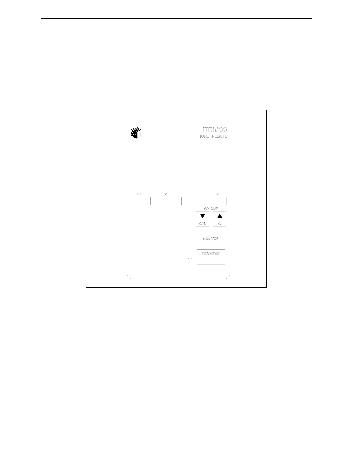
Desk Set Button Panel
Refer to the figure below for the locations of the buttons and LED on the desk set button panel.
F1, F2, F3, and F4 Frequency Buttons
Normally, these buttons are used to change channels on the radio. However, the use and function of these
buttons are dependent on your radio’s capabilities. Whenever a frequency button is pressed, the button
illuminates until a different frequency button is pressed.
Volume Buttons
The desk set includes two buttons labeled VOLUME. One is imprinted with an up arrow, and the other
with a down arrow. They are used to increase and decrease the local speaker volume and as programming
function keys.
01/05 4
Front View of the Desk Set Button Panel

ITR1000A Basic Tone Remote Desk Set Description
Control Button
The CTL button is used in conjunction with the VOLUME Up or VOLUME Down buttons to control the
local speaker. It is also used during programming.
Intercom Button
The Intercom button, labeled IC, allows communication between desk set users without transmission over
the radio.
Monitor Button
The MONITOR button is used to place the radio in the monitor mode.
Transmit Button
The TRANSMIT button is used to initiate voice transmissions. Pressing the TRANSMIT button places the
desk set in the transmit mode.
Transmit LED
The TRANSMIT LED illuminates when transmitting.
Internal Microphone
This microphone is intended for use in low noise environments. The handset must be on-hook in order to
use the microphone.
Handset
The desk set is equipped with a handset with a coil cord used for receiving and transmitting calls. The
handset includes a push-to-talk (PTT) pressbar.
5 01/05

Description ITR1000A Basic Tone Remote Desk Set
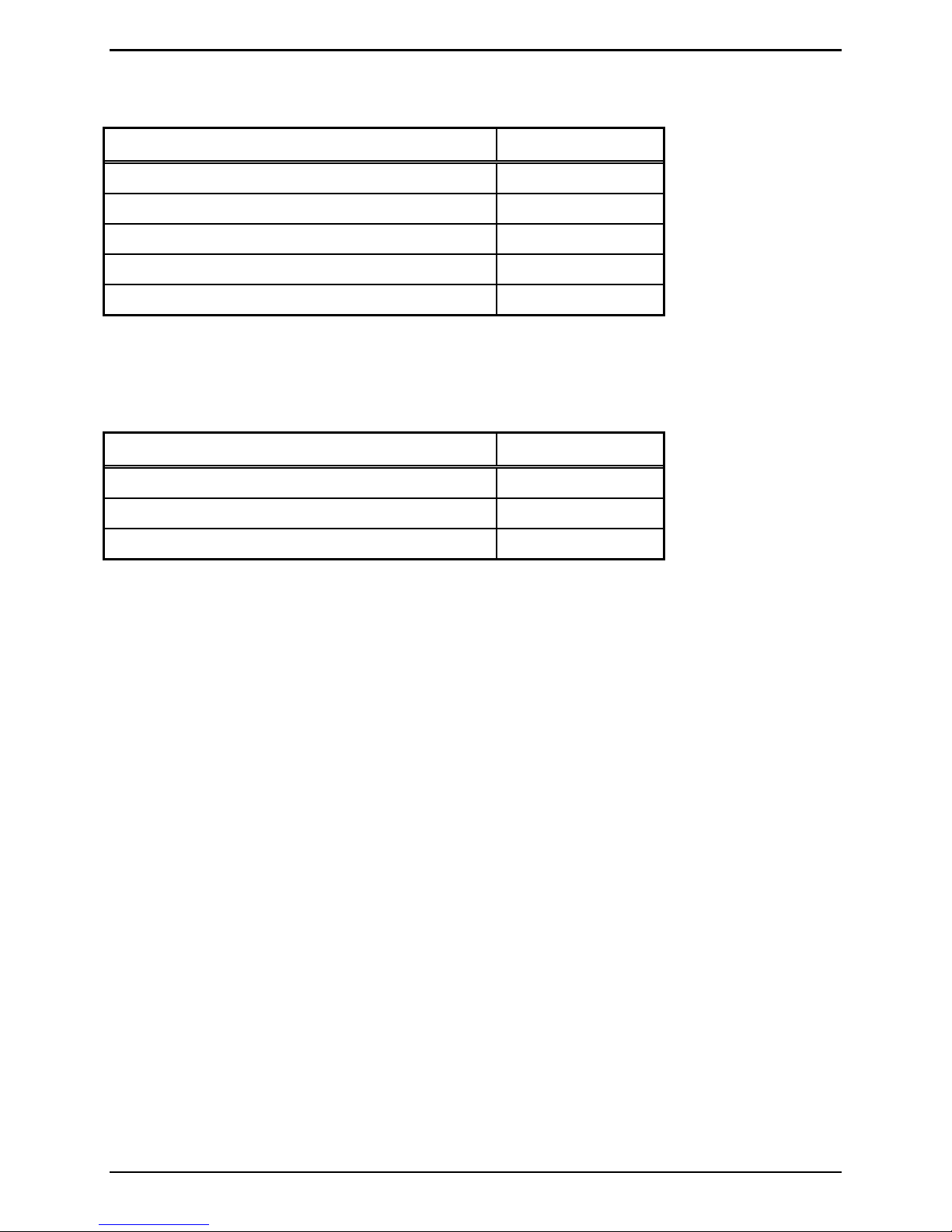
Programming Switches
A set of programming switches is included on the desk set. The switch settings are as follows:
SWA Switch Settings Table
Switch Determines: On Off (Default)
SWA-1 Whether the handset off-hook
Enabled Disabled
monitor is enabled or disabled
SWA-2 The frequency change commands Pressing the frequency
button does not
immediately change the
station frequency. It
Pressing the frequency
button immediately
changes the station
frequency.
changes only after TX or
handset PTT is pressed.
SWA-3 Not used. N/A N/A
SWA-4 Operation with handset removed Allows the use of the
internal mic and local
Handset must be present
for proper operation.
speaker without handset.
SWA-5 Not used. N/A N/A
SWA-6 Whether line termination is enabled
Disabled Enabled
or disabled
SWA-7 Guard tone keying Special application:
No function tones are
generated when TX or
Normal Operation:
Function tones are
generated prior to LLGT.
handset PTT is pressed.
SWA-8 Access to front panel programming
Disabled Enabled
mode is enabled or disabled
NOTE: The factory default for all SWA switches is off.
01/05 6
ITR1000A Basic Tone Remote Desk Set Description
ITR1000A Basic Tone Remote Desk Set Accessories
Description Part No.
Tone Remote Adapter ITA2000A
Audio Accessory Box XAAB002A
Desk Microphone* XDM002A
Footswitch* XFS002A
Lightweight Headset* XHS002A
*These accessories require the use of the XAAB002A Audio Accessory Box
ITR1000A Basic Tone Remote Desk Set Field Replacement Items
Description Part No.
Handset with Cord, Black HANDSET-BLACK
Replacement Power Supply 3308-50008-00
Speaker Assembly 61501-014
7 01/05

Description ITR1000A Basic Tone Remote Desk Set
Performance Specifications
Color ..................................................................................................................................................... Black
Physical size..................................................................................................... 7.6 W × 8.9 L × 4.7 H inches
Weight................................................................................................................................................. 2.4 lbs.
Temperature range.............................................................................................................. -35° C to +70° C
Humidity...................................................................................................... 95% at 50° C (non-condensing)
Line impedance................................................................................................................. 600 ohms nominal
Power input................................................................................................... 10.5-16 V dc; 0.5 A maximum
from Class 2 listed ac adapter
Nominal input level.......................................................................................................................... -10 dBm
Range -25 to 0 dBm into 560 ohms
Nominal output level........................................................................................................................ -10 dBm
Range -15 to +5 dBm into 560 ohms
Frequency response....................................................................... +3 dB, 300-3000 Hz (except notch filter)
Frequency stability............................................................................................................ Better than +1.0%
Hum and noise .................................................................................... Less than -45 dB below rated outputs
Audio output to speakers ................................................. 1 watt minimum with level in compression range
Audio distortion............................................................................................................... Less than 3% THD
Maximum number of remotes.................................................................................................................... 10
Control functions
Guard tone............................................................................................................................ 2175 Hz
F1......................................................................................................................................... 1950 Hz
F2......................................................................................................................................... 1850 Hz
F3......................................................................................................................................... 1750 Hz
F4......................................................................................................................................... 1650 Hz
(F1 through F4 can be programmed from 550 to 2050 Hz in 100 Hz increments)
Monitor ................................................................................................................................ 2050 Hz
(Monitor control function can not be programmed.)
Safety ..................................... Class III SELV-powered equipment. Powered by UL-listed (E104603) and
Emissions....................................................................................... USA: FCC Part 15, Sub. B-Verification
Line interface................................................. USA: FCC Part 68 Exempt (Category II Tariff #260 service
01/05 8
CSA certified (LR67888) ac adapter
Canada: ICES-003
for private/leased line applications)
Canada: Designed to meet IC CS03-8 (Certification pending)
 Loading...