

Page 1
Pub. 43004-027A
GAI-TRONICS® CORPORATION
A HUBBELL COMPANY
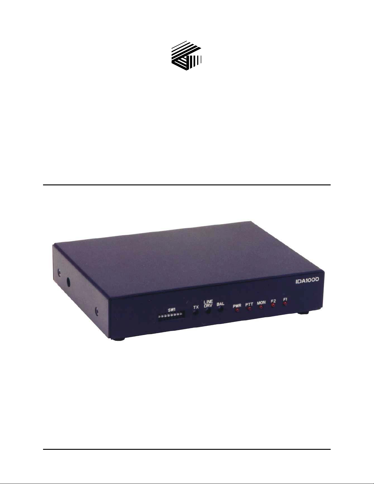
Model IDA1000A DC Remote
Adapter
Installation and Service Manual
GAI-Tronics Corporation 400 E. Wyomissing Ave. Mohnton, PA 19540 USA
610-777-1374 800-492-1212 Fax: 610-796-5954
V
ISIT WWW.GAI-TRONICS.COM FOR PRODUCT LITERATURE AND MANUALS
Page 2

CONFIDENTIALITY NOTICE
This manual is provided solely as an operational, installation, and maintenance guide and contains
sensitive business and technical information that is confidential and proprietary to GAI-Tronics.
GAI-Tronics retains all intellectual property and other rights in or to the information contained herein,
and such information may only be used in connection with the operation of your GAI-Tronics product or
system. This manual may not be disclosed in any form, in whole or in part, directly or indirectly, to any
third party.
COMPUTER SOFTWARE COPYRIGHTS
This product contains copyrighted computer programs stored in semiconductor memory. These programs
are copyrighted by GAI-Tronics Corporation and may not be reproduced in any form without express
written permission from GAI-Tronics.
WARRANTY
GAI-Tronics warrants for a period of one (1) year from the date of shipment, that any GAI-Tronics equipment supplied
hereunder shall be free of defects in material and workmanship, shall comply with the then-current product specifications and
product literature, and if applicable, shall be fit for the purpose specified in the agreed-upon quotation or proposal document. If
(a) Seller’s goods prove to be defective in workmanship and/or material under normal and proper usage, or unfit for the purpose
specified and agreed upon, and (b) Buyer’s claim is made within the warranty period set forth above, Buyer may return such
goods to GAI-Tronics’ nearest depot repair facility, freight prepaid, at which time they will be repaired or replaced, at Seller’s
option, without charge to Buyer. Repair or replacement shall be Buyer’s sole and exclusive remedy, and the warranty period on
any repaired or replacement equipment shall be one (1) year from the date the original equipment was shipped. In no event shall
GAI-Tronics’ warranty obligations with respect to equipment exceed 100% of the total cost of the equipment supplied hereunder.
The applicability of any such third-party warranty will be determined solely by GAI-Tronics.
Services. Any services GAI-Tronics provides hereunder, whether directly or through subcontractors, shall be performed in
accordance with the standard of care with which such services are normally provided in the industry. If the services fail to meet
the applicable industry standard, GAI-Tronics will, for a period of one (1) year from the date of completion, re-perform such
services at no cost to the Buyer. Re-performance of services shall be Buyer’s sole and exclusive remedy, and in no event shall
GAI-Tronics’ warranty obligations with respect to services exceed 100% of the total cost of services provided hereunder.
Limitations/Exclusions. The warranty on any equipment supplied hereunder is subject to Customer’s use in compliance
with applicable FCC regulations and manufacturer specifications. The warranties herein shall not apply to, and GAI-Tronics
shall not be responsible for, any damage to the goods or failure of the services supplied hereunder, to the extent caused by
accident, misuse, abuse, neglect, system design, product modification, failure to follow instructions contained in the product
manual, repair, or attempted repair by anyone not authorized by GAI-Tronics, improper installation, installation of parts that do
not conform to the quality or specifications of the original parts or accessories, damage or loss occurred during shipment, or any
unit which is not new when sold or upon which the serial number has been defaced, modified or removed. The warranty does
not extend to damage incurred by natural causes including Force Majeure. The warranty does not cover microprocessors if
failure is due to static damage or application of improper voltage.
THE WARRANTIES AND REMEDIES CONTAINED
HEREIN ARE IN LIEU OF AND EXCLUDE ALL OTHER WARRANTIES AND REMEDIES, WHETHER
EXPRESS OR IMPLIED BY OPERATION OF LAW OR OTHERWISE, INCLUDING ANY WARRANTIES OF
MERCHANTABILITY OR FITNESS FOR A PARTICULAR PURPOSE.
Operational and Maintenance Procedures. Buyer acknowledges that any improper use, maintenance, or
modification of the equipment provided hereunder, or use of unqualified maintenance or service technicians will severely impair
the operational effectiveness of the entire communication system. Buyer hereby agrees to indemnify, defend and hold GAITronics harmless from and against any and all third party claims arising, in any manner, out of: (a) Buyer’s neglect of the
equipment; (b) Buyer’s use of technicians not authorized by GAI-Tronics to service the equipment; or (c) Buyer’s improper use
or modification of the equipment or failure to follow the operational and maintenance procedures provided with the equipment.
Limitation of Liability/Damages. In no event (even should circumstances cause the exclusive warranties and remedies
set forth in the Warranty section to fail of their essential purpose) shall either party be liable for any indirect, incidental, special
or consequential damages (including, but not limited to, loss of use, loss of anticipated profits, or damages arising from delay)
whether such claims are alleged to have arisen out of breach of warranty, breach of contract, strict or absolute liability in tort, or
other act, error or omission, or from any other cause whatsoever, or any combination of the foregoing.
01/05 Publication 43004-027A i
Page 3

Table of Contents
FOREWORD...............................................................................................................................................................1
COPE OF MANUAL ....................................................................................................................................................1
S
OMENCLATURE........................................................................................................................................................1
N
RDERING REPLACEMENT PARTS ..............................................................................................................................1
O
ERVICE AND REPAIR.................................................................................................................................................1
S
NTERFERENCE WARNING..................................................................................................................................1
FCC I
AFE HANDLING OF CMOS INTEGRATED CIRCUIT DEVICES .....................................................................................2
S
DESCRIPTION ...........................................................................................................................................................3
F
EATURES AND BENEFITS OF THE MODEL IDA1000A DC REMOTE ADAPTER ..........................................................3
HYSICAL DESCRIPTION.............................................................................................................................................3
P
RONT PANEL ............................................................................................................................................................4
F
Programming Switches.........................................................................................................................................4
Front Panel LEDs.................................................................................................................................................4
INE LEVEL ADJUSTMENTS........................................................................................................................................4
L
TX Adjustment.......................................................................................................................................................4
Line DRV Adjustment ...........................................................................................................................................4
BAL Adjustment....................................................................................................................................................4
EAR PANEL ..............................................................................................................................................................5
R
CCESSORIES.............................................................................................................................................................5
A
ERFORMANCE SPECIFICATIONS ................................................................................................................................6
P
OPERATION...............................................................................................................................................................7
O
PERATIONAL DESCRIPTION......................................................................................................................................7
RONT PANEL LED OPERATION ................................................................................................................................8
F
PWR LED..............................................................................................................................................................8
PTT LED...............................................................................................................................................................8
MON LED.............................................................................................................................................................8
F2 LED .................................................................................................................................................................8
F1 LED .................................................................................................................................................................8
INSTALLATION ........................................................................................................................................................9
LANNING THE INSTALLATION...................................................................................................................................9
P
ECHANICAL RECEIPT INSPECTION ...........................................................................................................................9
M
OUNTING.................................................................................................................................................................9
M
NTERFERENCE WARNINGS................................................................................................................................9
FCC I
QUIPMENT REQUIRED...............................................................................................................................................9
E
ABLE INSTALLATION SAFETY CONSIDERATIONS....................................................................................................10
C
ELEPHONE LINE LIGHTNING AND OVER-VOLTAGE PROTECTION............................................................................10
T
OWER CONNECTIONS .............................................................................................................................................10
P
Power Connections Pin-out................................................................................................................................10
ADIO CONNECTIONS ..............................................................................................................................................11
R
Receive Audio – P1-11, Audio Ground; P1-3, to de-emphasized RX audio source...........................................11
Mic High and Mic Low – P1-12, Hi; P1-4, Low ................................................................................................11
Duplex Control – P1-2........................................................................................................................................11
F1 – P1-8............................................................................................................................................................11
PTT Output – P1-13 Active High; P1-6 Active Low...........................................................................................11
Monitor – P1-14 Active High; P1-7 Active Low.................................................................................................11
F2- P1-15............................................................................................................................................................11
01/05 Publication 43004-027A ii
Page 4

Table of Contents Model IDA1000A DC Remote Adapter
ACCESSORY CONNECTIONS......................................................................................................................................12
INE CONNECTIONS .................................................................................................................................................12
L
Radio and Accessory Connection Chart.............................................................................................................13
WITCH POSITIONS.........................................................................................................................................14
SW1 S
SW1 Switch Settings Table..................................................................................................................................14
UMPER POSITIONS...................................................................................................................................................15
J
Jumper Position Table........................................................................................................................................15
INE INPUT GAIN SELECT SWITCHES .......................................................................................................................15
L
EVEL SETTINGS AND ADJUSTMENTS ......................................................................................................................16
L
Line Drive Level .................................................................................................................................................16
Transmit Level....................................................................................................................................................16
DC Threshold Calibration..................................................................................................................................16
Balance Adjustment............................................................................................................................................16
THEORY OF OPERATION....................................................................................................................................17
OWER SUPPLY ........................................................................................................................................................17
P
ONTROL CURRENT DETECTION .......................................................................................................................17
DC C
UDIO CIRCUIT........................................................................................................................................................18
A
TROUBLESHOOTING............................................................................................................................................19
T
ROUBLESHOOTING THE MODEL IDA1000A DC REMOTE ADAPTER......................................................................19
USE REPLACEMENT ................................................................................................................................................20
F
MAIN CIRCUIT BOARD........................................................................................................................................21
SCHEMATICS..........................................................................................................................................................25
DEFINITIONS AND ACRONYMS.........................................................................................................................31
01/05 Publication 43004-027A iii
Page 5

Foreword
Scope of Manual
This manual offers descriptive data and service information for Model IDA1000A DC Remote Adapter
Service diagrams and printed circuit board details are a part of this service manual.
Nomenclature
The model number, located on the nameplate on the bottom, specifically identifies GAI-Tronics
equipment. If additional options are ordered, the option will be identified on the circuit board.
Ordering Replacement Parts
When ordering replacement parts or requesting equipment information, please include the complete
identification number. This applies to all components, kits, and chassis. If the component part number is
not known, the order should include the number of the chassis or kit of which it is a part and sufficient
description of the desired component to identify it. Order parts from:
Customer Service
GAI-Tronics Corporation
400 E. Wyomissing Ave.
Mohnton, PA 19540
US: 800-492-1212
Outside US: 610-777-1374
Service and Repair
Inoperative or malfunctioning equipment should be returned to the factory for repair. Please call
1-800-492-1212 to obtain a Return Authorization number, published repair prices, and shipping
instructions.
OTE: A purchase order or credit card number is required prior to processing non-warranty repairs.
N
FCC Interference Warning
The FCC requires that manuals pertaining to Class A and Class B computing devices must contain
warnings about possible interference with local residential radio and TV reception. This warning reads as
follows:
OTE: This equipment has been tested and found to comply with the limits for a Class A digital device,
N
pursuant to Part 15 of the FCC Rules. These limits are designed to provide reasonable protection against
harmful interference when the equipment is operated in a commercial environment. This equipment
generates, uses, and can radiate radio frequency energy and, if not installed and used in accordance with
the instruction manual, may cause harmful interference to radio communications. Operation of this
equipment in a residential area is likely to cause harmful interference in which case the user will be
required to correct the interference at his own expense.
1 01/05
Page 6

Foreword Model IDA1000A DC Remote Adapter
Safe Handling of CMOS Integrated Circuit Devices
Many of the integrated circuit devices used in communications equipment are of the Complementary
Metal Oxide Semiconductor (CMOS) type. Because of their high open circuit impedance, CMOS
integrated circuits are vulnerable to damage from static charges. Care must be taken handling, shipping,
and servicing them and the assemblies in which they are used.
Even though protection devices are provided in CMOS integrated circuit inputs, the protection is effective
only against overvoltage in the hundreds of volts range such as is encountered in an operating system. In
a system, circuit elements distribute static charges and load the CMOS circuits, decreasing the chance of
damage. However, CMOS circuits can be damaged by improper handling of the modules, even in a
system.
To avoid damage to circuits, observe the following handling, shipping, and servicing precautions:
1. Prior to and while servicing a circuit module, particularly after moving within the service area,
momentarily touch both hands to a bare metal, earth-grounded surface. This will discharge any static
charge that may have accumulated on the person doing the servicing.
OTE: Wearing a conductive wrist strap will minimize static build-up during servicing.
N
2. Whenever possible, avoid touching any electrically conductive parts of the circuit module with your
hands.
3. Power down the unit before installing or removing the circuit module.
4. When servicing a circuit module, avoid carpeted areas, dry environments, and certain types of
clothing (silk, nylon, etc.) because they contribute to static build-up. Similarly, disconnect the test
probe prior to removing the ground lead.
5. All electrically powered test equipment should be grounded. Apply the ground lead from the test
equipment to the circuit module before connecting the test probe.
6. If a circuit module is removed from the system, it is desirable to lay it on a conductive surface (such
as a sheet of aluminum foil) which is connected to ground through 100K of resistance.
7. When soldering, be sure the soldering iron is grounded and has a grounded tip.
8. Prior to connecting jumpers, replacing circuit components, or touching CMOS pins (if this becomes
necessary in the replacement of an integrated circuit device), be sure to discharge any static build-up
as described in procedure 1. Since voltage differences can exist across the human body, it is
recommended that only one hand be used if it is necessary to touch pins on the CMOS device and
associated board wiring.
9. When replacing a CMOS integrated circuit device, leave the device in its conductive rail container or
conductive foam until it is to be inserted into the printed circuit module.
10. All low impedance test equipment (such as pulse generators, etc.) should be connected to CMOS
device inputs after power is applied to the CMOS circuitry. Similarly, such low impedance
equipment should be disconnected before power is turned off.
11. Replacement modules shipped separately from the factory will be packaged in a conductive material.
Any modules being transported from one area to another should be wrapped in a similar material
(aluminum foil may be used). Never use non-conductive material for packaging these modules.
01/05 2
Page 7

Description
Features and Benefits of the Model IDA1000A DC Remote Adapter
Feature Benefit
Multiple dc remote support System flexibility and productivity are enhanced when several desk
sets are connected.
Two-channel control Model IDA1000A can be used to change channels and other
functions on certain radios.
Monitor Allows user to hear co-channel activity; CTCSS/CDCSS is disabled.
Full-duplex capable When used with a 2/4-wire capable desk set, provides full-duplex
operation for use with most full-duplex and trunking radio systems.
Adjustable receive input
sensitivity and transmit output
level
Selectable input/output logic
control
Accessory port Easily connects other devices such as a local desk set and telephone
Modular phone line connection on
back
AC or dc capable Uses power from radio or ac source (using optional wall transformer
Interfaces to most radio systems and line conditions.
The Model IDA1000A is flexible for many radio systems. Outputs
can be individually selected to go active high or to ground,
depending on the radio.
interconnect.
Provides easy-to-install phone line cable connection.
Part. No. 3308-00750-00).
Physical Description
The Model IDA1000A adapts remote desk set or console dc control to most radio systems with features
that exploit maximum functionality.
Adjustable input and output functions such as line input, transmit output level and selectable input/output
logic control provide flexibility. Easy connections and support of multiple desk sets make this dc adapter
the ideal choice for simple or complex desk set arrangements. One dc remote adapter can interface
several dc remote desk sets to the base station, depending on system design.
3 01/05
Page 8
Description Model IDA 1000A DC Remote Adapter
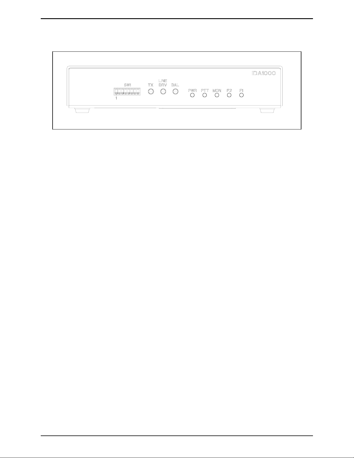
Front Panel
Figure 1. Front View of the Model IDA1000A DC Remote Adapter
Programming Switches
The programming switches (SW1) are used to set up and interface with the radio system. They are
numbered from left to right when viewed from the front.
Front Panel LEDs
The PWR LED indicates the remote adapter is on. The PTT LED illuminates when a valid transmit
request has been decoded. The
IDA1000A is in monitor mode. The
MON (timed or constant monitor) LED illuminates when the Model
F1 and F2 LEDs indicate current frequency and/or other functions.
Line Level Adjustments
TX Adjustment
The TX adjustment pot sets the level of the transmit audio to that required to properly modulate the base
station’s transmitter.
Line DRV Adjustment
The LINE DRV adjustment is used to set the telephone (audio) line level or “drive” to the remote desk set
or console.
BAL Adjustment
The balance potentiometer (BAL) allows optimizing the hybrid RX to TX isolation of the internal hybrid
in the 2-wire mode.
01/05 4
Page 9
Model IDA 1000A DC Remote Adapter Description
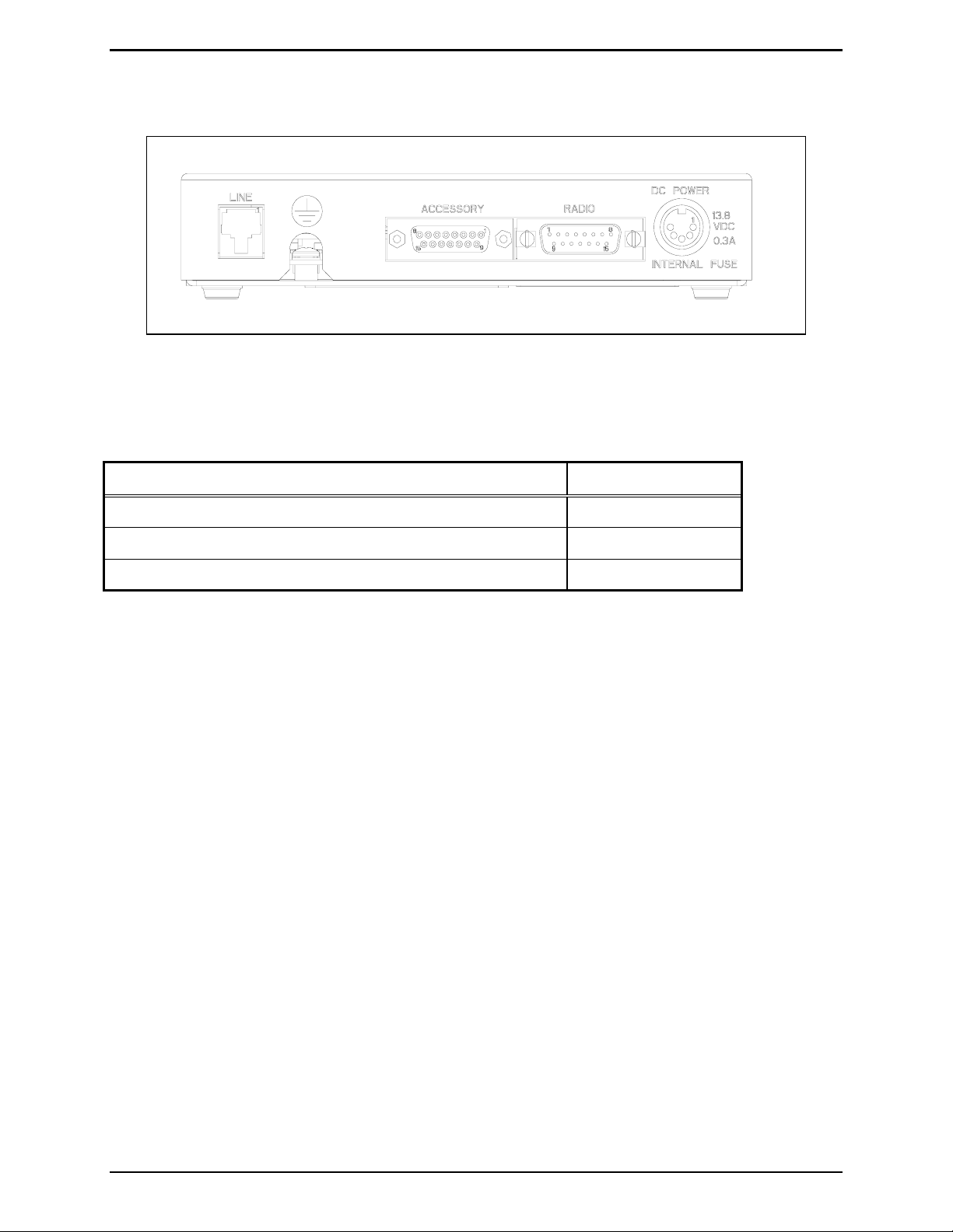
Rear Panel
Figure 2. Rear View of the Model IDA1000A DC Remote Adapter
Accessories
Description Part No.
AC Wall Transformer 3308-00750-00
Rack-Mount Kit (Standard 19-inch W × 1.75-inch H)
4-Wire Field Install Kit XDA0001A
XAC0005A
5 01/05
Page 10

Description Model IDA 1000A DC Remote Adapter
Performance Specifications
Color ......................................................................................................................................................Black
Physical size.............................................................................................................7.02 W × 5.3 L × 1.35 H
Weight.....................................................................................................................................................4 lbs.
Temperature range..................................................................................................................-30º C to 70º C
Humidity.......................................................................................................95% at 50º C (non-condensing)
Power input..........................................................................................10.5 to 16 V dc at 300 mA maximum
Hum and noise ..................................................................................... Less than –45 dB below rated output
Audio distortion................................................................................................................Less than 3% THD
RX input.....................................................................................32 mV ac to 4.5 V ac (nominal 300 mV ac)
TX input.............................................................. 32 mV ac to 800 mV ac in 560 ohms (nominal 80 mV ac)
Line input.........................................................................-25 to 0 dB ALC to reference (nominal –10 dBm)
Line output................................................... -15 to +10 dBm adjustable into 560 ohms (nominal –10 dBm)
Maximum desk sets supported...................................................................10 maximum (per system design)
DC current defaults......................................................................................................................F1: 5.5 mA
F2: 12.5 mA
Monitor: -2.5 mA
01/05 6
Page 11

Operation
Operational Description
The Model IDA1000A DC Remote Adapter is for use with base stations or repeaters controlled from a
remote desk set or console by dc line currents. One adapter can interface up to ten dc remote desk sets to
the base station or repeater, depending on the system design.
The Model IDA1000A incorporates all necessary circuit interfacing to translate single-frequency
(5.5 mA) transmit and monitor (-2.5 mA) commands into signals to control base station operation. Where
applicable, F2 transmit (12.5 mA) commands are also supported when used with a two-frequency base
station. Frequency outputs are jumper-selectable for open collector, 5 V pull up, or pull down. The
Model IDA1000A can be programmed to revert to F1 or F2 receive after transmit. See the SW1 Switch
Settings Table on page 14.
Monitor operation can be either latching or non-latching. The adapter routes audio signals between the
wire line and base station circuitry. Transmit audio from the wire line is amplified before being input to
the station. Receiver audio from the base station is amplified before being output to the wire line.
The amount of gain set by the adapter will operate full duplex with either 2-wire or 4-wire. The balanced
inputs cancel ac line noise.
Five LED function indicators are included on the front panel. When illuminated, they indicate wire line
push-to-talk command, a monitor command, and presence of 5 V dc power. Two LEDs indicate detection
of line current levels of 5.5 mA (
F1) or 12.5 mA (F2).
7 01/05
Page 12

Operation Model IDA 1000A DC Remote Adapter
Front Panel LED Operation
The operation of the IDA1000A DC Remote Adapter front panel LEDs is as follows:
PWR LED
The PWR LED illuminates to indicate that the IDA1000A DC Remote Adapter dc power is on.
PTT LED
The push-to-talk LED, labeled PTT, illuminates when a valid transmit request has been decoded.
MON LED
The timed or constant monitor LED, labeled MON, illuminates when the IDA1000A is in the monitor
mode, and indicates detection of a line current level of -2.5 mA.
F2 LED
The front panel F2 LED indicates detection of line current level of 12.5 mA (F2). It illuminates to
indicate that the unit is programmed to use the F2 transmit (12.5 mA) command, which is supported when
used with a two-frequency base station.
F1 LED
The front panel F1 LED illuminates to indicate that the unit is programmed to translate the singlefrequency (5.5 mA) transmit command into signals to control base station operation. The IDA1000A
may be programmed to revert to F1 or F2 receive after transmit.
01/05 8
Page 13

Planning the Installation
Sample Installation Diagram - Shown connected in parallel within one building.
Installation
Mechanical Receipt Inspection
The Model IDA1000A DC Remote Adapter is shipped in a cardboard container with inserts. Thoroughly
inspect it as soon as possible after delivery. In-transit damage should be immediately reported to the
transportation company.
Mounting
The Model IDA1000A can be installed in a custom-supplied rack or cabinet (with XAC0005A RackMount Kit) or can be placed on a desk for convenience when used with accessories.
FCC Interference Warnings
The FCC requires that manuals pertaining to Class A and Class B computing devices contain warnings
about possible interference with local and residential radio and TV reception. Please read these warnings
and all safety information in the Foreword section of this manual.
Equipment Required
Test Equipment
• RF service monitor
• AC voltmeter with dB ranges for measuring audio levels
• #1 Phillips screwdriver
• 1/8-inch flat blade screwdriver
Documentation
• base station's tone remote adapter manual
• these installation instructions
9 01/05
Page 14

Installation Model IDA 1000A DC Remote Adapter
Cable Installation Safety Considerations
Interconnecting, communications, and Class 2 dc power cables should be separated from electrical light
or other Class I circuits by at least 2 inches. The exception is where Class I wiring or power circuits are
run in a raceway, or are metal-sheathed or metal-clad, or are permanently separated from the conductors
of the other circuitry by a continuous and firmly fixed nonconductor such as porcelain tubes or flexible
tubing in addition to the insulation on the wire. Communications cables and in-building wiring should be
listed and marked for the purpose according to NEC Article 800.
Telephone Line Lightning and Over-voltage Protection
For maximum surge and lightning protection, building primary (over-voltage) protectors should be
installed at the point where the phone lines enter the radio equipment building. Primary protectors are
usually required by local codes and should be provided by your local exchange carrier.
The Model IDA1000A has over-current phone line fuses F2 (main) and F3 (4-wire option board), which
protect against occasional extreme fault conditions that may get past the primary protectors. An example
of such a fault condition is a power line cross. If the fuse requires replacement, replace it with the same
type Bussmann C515S 1.25A SB fuse.
Power Connections
Connections should be made to a 10.5 to 16 V dc source capable of supplying up to 300 mA. An optional
120 V ac wall transformer (Part No. 3308-00750-00) should be used if a suitable dc source is not
available.
The Model IDA1000A provides active low outputs referenced to system ground (negative ground
system). To interface with a positive ground radio station, or a radio needing active high signals, requires
relays or opto-isolators, which translate the adapter outputs.
Power Connections Pin-out
Pins Position
Pins 3 and 5 +IN
Pins 1 and 4 -IN
Pin 2 Battery +
Figure 3. Optional 5-Pin DIN
Power Supply
01/05 10
Page 15

Model IDA1000A DC Remote Adapter Installation
Radio Connections
Radio connections are made via P1. See Figure 4 on page 13. The supplied radio cable can be removed
if not needed, and a connector or terminal appropriate for the station used can be installed.
Receive Audio – P1-11, Audio Ground; P1-3, to de-emphasized RX audio source.
This input uses dc blocking capacitors on each side; reference level input at 2/3 radio system modulation
is 600 mV ac. Receive “audio in” can be configured for balanced or single-ended audio.
• If balanced, both pins should be connected. If single-ended audio is used, P1-11 should be grounded
to audio or chassis ground.
• Receive input audio can be configured for 32 to 150 mV ac, 150 to 400 mV ac, 400 mV ac to 1.7 V
ac, or 1.7 V ac to 4.5 V ac using SW1-3 and JU3. See the Jumper Position Table on page 15.
• To determine the correct setting, measure the receive audio output with 2/3 maximum deviation
applied where pins P1-11 and P1-3 will be connected.
Mic High and Mic Low – P1-12, Hi; P1-4, Low
This output uses a dc blocking capacitor. P1-12 goes to the capacitor’s + side and is connected to the
station transmit audio. Common mode noise is detected by internal circuitry, correcting the mic high
signal.
• The return, P1-4, should connect to mic low or station audio ground.
• The reference output is 80 mVac into 560 ohms.
Duplex Control – P1-2
This is an input that routes radio supervisory talk permit and button-acknowledge tones to the adapter.
Connect to RX audio enable high/disable low output from the radio.
F1 – P1-8
In a multi-frequency radio, connect to the F1 oscillator ground or enable. In single-channel radios, this
input is normally not connected. This uncommitted collector transistor switch is capable of driving 100
mA, and is Zener-protected to +5 V.
PTT Output – P1-13 Active High; P1-6 Active Low
Connect to radio station PTT (TX) input. These are uncommitted collector transistor switches, capable of
driving 100 mA maximum and Zener-protected to +15 V.
Monitor – P1-14 Active High; P1-7 Active Low
This uncommitted collector transistor switch is capable of driving 100 mA maximum and Zener-protected
to +15 V.
• Connect P1-7 to radio station monitor input if GND is required for monitor.
• Connect P1-14 if high is requested.
F2- P1-15
In a multi-frequency radio, connect to the F2 oscillator ground or enable. This is an uncommitted
collector transistor switch, capable of driving 100 mA maximum and Zener-protected to +5 V.
11 01/05
Page 16

Installation Model IDA 1000A DC Remote Adapter
Accessory Connections
Accessory connections are made to the 15-pin accessory connector, located on the rear of the unit.
Numeric designations and functions are parallel to the radio pin numbers and functions as described
above. Input and output signals are opposite those of the radio connections.
Line Connections
The landline RJ11/RJ14 connector to J1 is polarity sensitive and must be wired to the modular connector
as follows:
• Pins 3 (dc control negative) and 4 (dc control positive) for 2-wire TX/RX operation.
• Pins 2 and 5 connect to the 4-wire receive landline pair if the E376AG 4-wire option has been
installed. The 4-wire receive-only pair is not polarity sensitive.
• Pins 1 and 6 are not used on the RJ11 (2-wire) or RJ14 (4-wire) connector.
OTE: Pin 1 is on the right-hand side looking into the modular connector.
N
01/05 12
Page 17

Model IDA1000A DC Remote Adapter Installation
Radio and Accessory Connection Chart
Radio connections are made via P1-1 to P1-15. J3-1 to J3-15 accessory connections correspond
numerically and functionally.
Pin Wire Input/ Output Nominal
# Color Description Radio Acc. Range Default
1 Blk/Wht dc+ (not used) JU12 Power input B+ V dc
2 Blu/Wht Duplex control JU10
I
3 Green RX audio + I O Range 1: 32 mV–400 mVRMS
I Enable high (+5 V dc)
Disable low (0 V dc) RX audio
0 V dc
300 mV
RMS
Range 2: 400 mV–4.5 VRMS
See Jumper Position Table.
4 Black Mic low (AGND) 0 V dc
5 Wht/Blk Not used.
6 White PTT (push-to-talk) O I Active low (GND)
0 V dc
(B+ unkeyed)
7 Orange Monitor O I Active low (GND)
0 V dc
(B+ unkeyed)
8Red F1 O I
Low (0 V dc) or high (+5 V dc) 0 V dc
JU15
9 Red/Wht dc– (not used) JU13 Power input 0 V dc
10 Grn/Wht Not used
11 Grn/Blk RX audio - I O
12 Blue TX audio (Mic Hi) O I 32 mV–800 mVRMS 560 ohms 80 mVRMS
13 Blu/Blk PTT (push-to-talk) O I Active high (B+) (GND
B+ V dc
unkeyed)
14 Org/Blk Monitor JU11
O
I Active high (B+) (GND
unkeyed)
B+ V dc
15 Rd/Blk F2 O I
Low (0 V dc) or high (+5 V dc) 0 V dc
JU14
*NOTE: Colors apply to the supplied GAI-Tronics cable.
Possible accessories include external speaker, telephone interconnect, local desk set, tone remote adapter,
or paging encoder.
1
9
8
15
Figure 4. P1 Radio Connector Mating Side Pin
Contacts
8
15
Figure 5. J3 Accessory Connector Mating Side
Socket Contacts
1
9
13 01/05
Page 18

Installation Model IDA 1000A DC Remote Adapter
SW1 Switch Positions
There are eight section switches (SW1) on the front panel of the Model IDA1000A housing. See Figure 1
on page 4. A switch is closed when in the down position, and open in the up position. Refer to the tables
that follow for switch position and function information.
SW1 Switch Settings Table
SW1
Section Position Function
1Down
Up
2Up
Down
3 Up with JU3 Out
Down with JU3 Out
Up with JU3 In
Down with JU3 In
4Down
Up
5 & 6 5 & 6 down
Duplex hybrid enabled
Duplex hybrid disabled (default)
Transmit output range -15 dBm to 0 dBm
Transmit output range -25 dBm to -15 dBm (default)
Line input range: 32 mV ac to 150 mV ac
Line input range: 150 mV ac to 400 mV ac (default)
Line input range: 400 mV ac to 1.7 V ac
Line input range: 1.7 V ac to 4.5 V ac
Monitor function enabled only for duration of monitor command
(default).
Monitor function remains enabled after receiving a monitor command
and until a transmit command is received.
Special application: neither frequency is selected during receive
condition (default).
5 & 6 up
5 down
Radio remains on whatever frequency the last transmission occurred.
Radio reverts to frequency F1 after every transmission regardless of
frequency of previous broadcast (when SW1 section 6 is up).
6 down
Radio reverts to frequency F2 after every transmission regardless of
frequency of previous broadcast (when SW1 section 5 is up).
7Down
Up
8Down
Up
Provides line termination for incoming signals (default).
Does not terminate line.
Half-duplex operation (default).
Allows remote user to hear supervisory talk permit and button
acknowledge tone from the radio (requires SW1 section 1 to be down
and appropriate adjustment of Pot 3).
01/05 14
Page 19

Model IDA1000A DC Remote Adapter Installation
Jumper Positions
The IDA circuit board contains nine jumpers, JU1 through JU5, and JU10 through 13. See board layout
in the Main Circuit Board section. The default setting provides normal operation. It should be changed
only for special applications.
Jumper Position Table
Jumper Position Function
JU1 3
1*
JU2 Out
In*
JU3 Out*
In
JU4 A
B*
JU5 A
B*
JU10-13 Out* Special applications only.
Line driver disable
Line driver enable
4-wire (if XDA0001A option is installed)
2-wire
SW1-3 Up - Line input range: 32 mV ac to 150 mV ac
SW1-3 Down – Line input range: 150 mV ac to 400 mV ac
SW1-3 Up – Line input range: 400 mV ac to 1.7 V ac
SW1-3 Down – Line input range: 1.7 V ac to 4.5 V ac
High output for F1
Low output for F1
High output for F2
Low output for F2
*Indicates the default positions.
Line Input Gain Select Switches
For SW1 sections 2 and 3, the default setting is down. These should be changed only if one of the remote
units has wire line losses of 10 dB or more. Select a gain setting to compensate for the unit with the most
loss. Adjust all other units to give identical transmit levels. To make adjustments:
1. Apply a 1000 Hz tone at the desired line level, e.g. 0 dBm at the remote end of the wire line to be
tested.
CAUTION
Do not exceed the recommended operating level of the line. Consult the line provider for this
information.
2. Measure and record the level at the remote adapter end with the adapter connected to the line. Do this
for each line attached.
3. Select the gain that best compensates for the line with the most loss. Start with the desk set that has
the most line loss and use the recommended mic input level from the desk set adjustment instructions.
Adjust the line driver on each desk set to obtain a 2/3 system deviation (nominally 80 to 165 mV ac).
15 01/05
Page 20

Installation Model IDA 1000A DC Remote Adapter
Level Settings and Adjustments
Line Drive Level
Set the line drive level as follows:
1. With a service monitor connected to the receiver with maximum allowable system deviation, measure
the audio across P1-11 and P1-3.
2. Set jumper JU3 and switch SW1-3 for the level indicated. See the Jumper Position Table on page 15.
3. While measuring the input to the line J1-3 and J1-4 (on 4-wire installations, J1-2 and J1-5), adjust
Pot 1, the adapter
allowable.
Transmit Level
Setting the transmit level compensates for any losses in the audio control line. The transmit level is set as
follows:
1. Apply a 1000 Hz signal to the mic circuit of the remote desk set. This signal should be enough to
provide the desired reference level across the audio control line at the desk set end, normally
-10 dBm.
LINE DRV level pot, for the desired level of drive, but no greater than the maximum
2. Adjust Pot 2, the adapter TX level pot, to obtain 2/3 system deviation from the base station
transmitter. If it is not possible to obtain the correct level near the center of the control’s travel, use
the opposite position for Gain Select, SW1-2.
DC Threshold Calibration
The dc threshold level is factory set and should not require adjustment unless field service is required. If
field service is necessary, complete the following steps:
1. Apply a –2.5 mA source to the control line.
2. Slowly adjust Pot 4, the calibration pot, to illuminate the
3. Remove the –2.5 mA current. The
Balance Adjustment
MON LED should extinguish.
MON LED.
The hybrid adjustment is factory-set and should not require adjustment. If field service is necessary,
complete the following steps:
1. Set switch SW1-8 up and SW1-1 down.
2. Adjust Pot 4 to full clockwise position.
3. Apply a 1000 Hz signal to P1-3/P1-11.
4. Measure the audio across P1-12/P1-4 and adjust Pot 3, the adapter
01/05 16
BAL pot, to null (minimum).
Page 21

Theory of Operation
Power Supply
The power supply for the remote adapter operates in the linear serial-pass mode. Programmable Zener U4
serves as reference for the 5 V digital power supply. The reference voltage is 5.00 V dc, +/- 0.1 V dc
measured at emitter Q5. Op-amp U1a controls the series pass element Q5 to provide 5 V dc at the 5 V
source point and the power LED provides indication of this voltage level. The reference voltage from U4
is scaled and isolated through U1b to provide a 2.5 V source.
DC Control Current Detection
Audio and dc control line currents are input to the circuit board through pins 3 and 4 of modular
connector J1. AC current is shunted across the transformer secondary by C1, and dc current is developed
across R1. The dc current is translated to a voltage (referenced to 6 V) by amplifier U5 and fed to U6a, b,
c, and associated components.
If the translated voltage were produced by a line current greater than or equal to 4.4 mA (indicating a
transmit command), then U6-1 would output a high level voltage; if the translated voltage were produced
by a line current greater than or equal to 9 mA, then U6-7 would output a high level voltage. If the
translated voltage were produced by a line current of negative polarity and greater than or equal to 2 mA
(indicating a monitor command), then U6-14 would output a high level voltage.
A high signal on U6-1 forces a low at U7-1 (illuminating LED 2) and U8-1, resulting in a high at U7-4
(after a delay through R71 and C20, C52) which then opens the audio path from the wire lines to the
station, drives Q1(Q6) and thus forces transmission on F1 (in a multi-frequency station), and forces
Q3(Q8) to output an active low (high) on the push-to-talk line. The low at U7-1 disables the receive
audio path from the station when SW1 section 8 is down.
In a 2-frequency station, a high on U6-7 drives Q2(Q7) through NOR gates U9b and U9c and thus forces
transmission on F2. The circuitry consisting of latch U8b and U8c, U8a, U8d, U9 guarantees that the F1
line will be disabled in the event of an F2 command. Switch SW1–5 may be pushed down (with SW1-6
up) to cause the transmit frequency to revert to F1 subsequent to every transmit command; switch SW1-6
may be pushed down (with SW1-5 up) to cause the transmit frequency to revert to F2 subsequent to every
transmit command.
A high signal on U6-14 forces U7-10 low (illuminating LED 3) and U7-13 high, thus enabling transistor
Q4(Q9) to output an active low on the monitor line. If switch SW1-4 is up, the monitor function will
remain enable subsequent to a monitor command and until a transmit command is received. This function
is accomplished by the latch configuration of U7c and U7d.
A low on U9-4 (indicating detection of a line current greater than or equal to 9 mA) illuminates LED 4; a
low on U9-13 (indicating detection of a line current greater than or equal to 4.4 mA) illuminates LED 5.
17 01/05
Page 22

Theory of Operation Model IDA1000A DC Remote Adapter
Audio Circuit
Receiver audio to be output on the control lines at J1 is input to the circuit board on P1-11, 3. These
signals are scaled through amplifier U2a, U10b and fed through the line audio adjustment, pot 1. The
resulting signal is gated to the line driver U11, U10a, and associated components.
Transmitter audio is input to the remote adapter through J1-3, 4, routed through transformer T1, and
scaled through U1c, U1a, U2c, and associated components. The line output gain may be set by proper
configuration of switch SW1-2.
The signal exiting U2c is fed through the line output adjustment, pot 2 and gated through U3a to the mic
hi input to the base station on P1-12.
01/05 18
Page 23

Troubleshooting
Troubleshooting the Model IDA1000A DC Remote Adapter
The following is a list of potential problems you may encounter and possible solutions.
Problem Possible Solution
General problems Ensure that there is a valid circuit line path from the desk set to the dc remote
adapter.
Check for a blown fuse and ensure that the dc remote adapter is connected to
a properly functioning dc power source (if using a dc power supply option).
The IDA1000A will not
key the radio.
Radio is keyed constantly
while the IDA1000A is
connected.
RX audio is low or
distorted.
There is constant white
noise in RX audio.
There is no RX audio. Check fuse F3 (4-wire option)
There is no TX audio. Verify that the radio is being keyed when transmitting to the IDA1000A from
Ensure that one of the IDA1000A PTT outputs is connected to the radio.
Check the telephone line continuity from the desk set to the remote adapter.
Reversed phone line pins 3 and 4.
Ensure that the telephone line is generating a current that the IDA1000A uses
for keying the radio.
Ensure that the PTT is in the proper active state:
P1-6 Ground keying
P1-13 B+ keying
Ensure that the IDA1000A receive sensitivity is set properly.
Ensure that there is no more than 20 dB loss in the telephone line.
Obtain RX audio from a muted source in the station and not ‘raw
detector/disc. audio.’ See radio manuals.
Check radio cable connections to radio’s RX audio source.
a dc remote.
Verify that the IDA1000A output level is properly set and there is not more
than 20 dB of loss in the telephone line.
Open fuse F2. (See fuse replacement information below.)
TX audio is distorted. Verify that the dc adapter transmit audio output is not set too high for the
radio’s expected input level. Adjust the TX audio level pot for proper setting.
TX level is set too high or SW1-2 is set to wrong position.
IDA1000A does not
transmit or receive.
Ensure that there is a telephone line audio path from the IDA1000A to the dc
desk set.
19 01/05
Page 24

Troubleshooting Model IDA1000A DC Remote Adapter
Fuse Replacement
CAUTION
For continued safe operation, replace fuses with the same type:
• F1 is a Bussmann 0.5A Type GMA, FB fuse.
• F2 on the main board and F3 on the 4-wire option board are Bussmann C515S 1.25A 2AG SB.
01/05 20
Page 25

Main Circuit Board
21 01/05
Page 26

Main Circuit Board Model IDA1000A DC Remote Adapter
22
Page 27

Model IDA1000A DC Remote Adapter Main Circuit Board
23
Page 28

Main Circuit Board Model IDA1000A DC Remote Adapter
24
Page 29

Schematics
25 01/05
Page 30

Schematics Model IDA1000A DC Remote Adapter
Schematic - Sheet 1
26
Page 31

Model IDA1000A DC Remote Adapter Installation and Service Manual Schematics
Schematic Diagram - Sheet 2
27
Page 32

Schematics Model IDA1000A DC Remote Adapter
Schematic Diagram - Sheet 3
28
Page 33

Model IDA1000A DC Remote Adapter Installation and Service Manual Schematics
Schematic Diagram - Sheet 4
29
Page 34

Schematics Model IDA1000A DC Remote Adapter
Notes:
30
Page 35

Term Definition
Definitions and Acronyms
CSQ
CTCSS
CDCSS
HLGT
LLGT
PTT
Carrier squelch
A means of grouping users of a common radio channel. Subaudible tones are transmitted
with audio; a particular radio's speaker (or the speakers of a group of radios) will unmute
to broadcast a transmission only if the associated subaudible tone identifies it as
belonging to the radio's user group.
A system analogous to CTCSS but using low speed digital signaling instead of subaudible
tones.
High level guard tone
Low level guard tone
Push-to-talk
31 01/05
Page 36

Notes: Model IDA 1000A DC Remote Adapter
32
 Loading...