

Page 1

Pub.: 42004-679L2D
GAI-TRONICS® CORPORATION
A HUBBELL COMPANY
Model DEX-101, -102, -201, and -202
Hazardous Area Driller’s Intercom Stations
T ABLE OF C ONTENTS
Confidentiality Notice.....................................................................................................................1
General Information.......................................................................................................................1
Product Overview...................................................................................................................................1
System Requirements and Limitations.................................................................................................1
Features and Functions..........................................................................................................................2
Available Models.....................................................................................................................................2
Description of Major Components........................................................................................................2
Installation ......................................................................................................................................3
General Information............................................................................................................................... 3
Mounting..................................................................................................................................................5
Conduit Installation................................................................................................................................5
Field Wire Installation............................................................................................................................6
Power........................................................................................................................................................7
AC Models............................................................................................................................................................7
DC Models............................................................................................................................................................7
Auxiliary Devices....................................................................................................................................8
System Interconnection..........................................................................................................................9
Operation.......................................................................................................................................10
Digital Models DEX-102 and DEX-202...............................................................................................10
Intercom Communication Modes........................................................................................................................10
Volume Control ..................................................................................................................................................10
Paging .................................................................................................................................................................11
Alarms and Music...............................................................................................................................................11
Analog Models DEX-101 and DEX-201..............................................................................................11
Intercom Communication Modes........................................................................................................................11
Volume Control ..................................................................................................................................................11
Paging .................................................................................................................................................................11
Alarms and Music...............................................................................................................................................11
Maintenance..................................................................................................................................12
General Information............................................................................................................................. 12
Troubleshooting....................................................................................................................................12
Specifications ................................................................................................................................13
GAI-Tronics Corporation 400 E. Wyomissing Ave. Mohnton, PA 19540 USA
610-777-1374 800-492-1212 Fax: 610-796-5954
V
ISIT WWW.GAI-TRONICS.COM FOR PRODUCT LITERATURE AND MANUALS
Page 2
42004-679L2D
GAI-TRONICS® CORPORATION
A HUBBELL COMPANY
Model DEX-101, -102, -201, and -202
Hazardous Area Driller’s Intercom Stations
Confidential ity Notice
This manual is provided solely as an operational, installation, and maintenance guide and contains
sensitive business and technical information that is confidential and proprietary to GAI-Tronics. GAITronics retains all intellectual property and other rights in or to the information contained herein, and
such information may only be used in connection with the operation of your GAI-Tronics product or
system. This manual may not be disclosed in any form, in whole or in part, directly or indirectly, to any
third party.
General Information
Product Overview
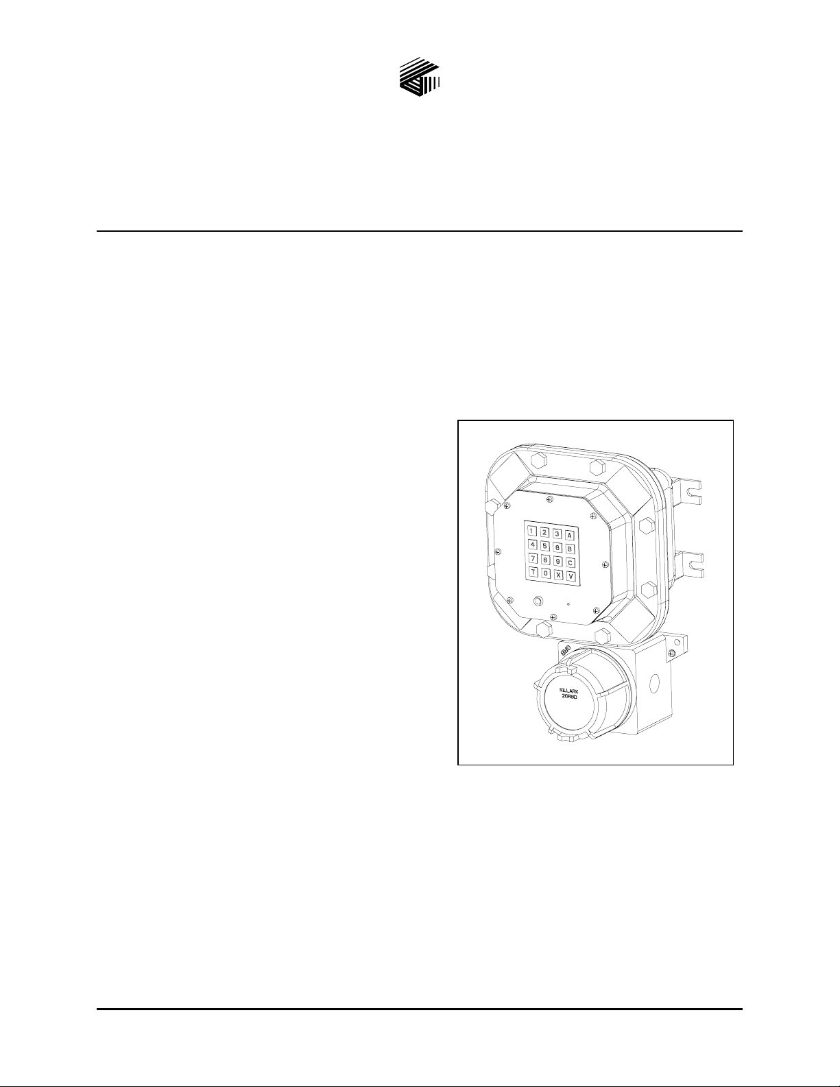
The Driller’s Intercom is a communications system
designed to serve the needs of oil and gas industry on
oil drilling platforms, especially in hazardous areas. It
provides all-call, group call, and point to point
communications, and is available in digital and analog
versions.
The enclosure is rated NEMA-4X, and is factory sealed
to ensure explosion-proof integrity.
System Requirements and Limitations
Each Driller’s Intercom system requires a Central
Switch to operate. The Central Switch must be located
in a non-hazardous area. The configuration parameters
for all components of the system are set in the Central
configuration.
Each central switch can manage up to 16 digital or analog subscribers, and can be expanded to 32
subscribers. Central switches can be linked or a larger switch can be used for increased system size. By
combining central switches, the system is easily expanded at any time.
All stations must be connected in a star configuration to the Central Switch, but power to the stations can
be daisy-chained. Please refer to the “Installation” section for the power cable and system cable distance
limitations.
Additional features and functions (not detailed in this manual) are available. Refer to the Central Switch
manual or contact a GAI-Tronics Corporation representative for more details.
GAI-Tronics Corporation 400 E. Wyomissing Ave. Mohnton, PA 19540 USA
610-777-1374 800-492-1212 Fax: 610-796-5954
V
ISIT WWW.GAI-TRONICS.COM FOR PRODUCT LITERATURE AND MANUALS
Figure 1. Driller’s Intercom with Keypad
Page 3

Pub.: 42004-679L2D
ODEL DEX-10X AND DEX-20X DRILLER’S INTERCOM STATIONS Page 2 of 13
M
Features and Functions
• Digital and analog models • Factory sealed
• 120–240 V ac and 24 V dc models • Suitable for Div. 1 & 2 and Zone 1 & 2 Hazardous Areas
• NEMA-4X rated enclosure • Suitable for high noise areas
• 18-watt speaker amplifier • Hands-free duplex and simplex communication
• Speaker volume control • All-call and group paging
• Beacon control (digital models only) • Broadcast of alarm and music signals
• Footswitch input • Master/slave and point-to-point communications
• Call status indicator • System upgrade and expansion capability
• UL Approved
Available Models
DEX-101
DEX-201
DEX-102
DEX-202
Analog Intercom Station - 24 V dc (UL)
Analog Intercom Station – 120 V ac (UL)
Digital Intercom Station with keypad – 24 V dc (UL)
Digital Intercom Station with keypad – 120 V ac (UL)
Description of Major Components
The Driller’s Intercom stations consist of a factory-sealed enclosure (top) and a termination enclosure
(bottom). Refer to Figure 1 for details. The factory-sealed configuration eliminates the need for external
seals on this unit; however, additional seals may be required on auxiliary devices.
The audio, control, and power components for this assembly are contained in the factory-sealed
enclosure. The front panel of the factory-sealed enclosure contains the user interface components
(microphone, status LED, and keypad [digital models only]).
All system terminations (power, speaker, system, footswitch, and beacon) are to be made in the
termination enclosure.
This station requires an external speaker (sold separately) to operate. Also, a customer-supplied beacon
(digital models only) and footswitch can be added to this unit for visual status indication and talk/listen
control.
CAUTION
f:\standard ioms - current release\42004 instr. manuals\42004-679l2d.doc
10/10
Use only suitably listed components for the hazardous area.
Page 4

Pub.: 42004-679L2D
ODEL DEX-10X AND DEX-20X DRILLER’S INTERCOM STATIONS Page 3 of 13
M
Installation
General Information
WARNING
Always remove power to this station and any associated equipment before
beginning any installation.
Install equipment without modification and according to all applicable local and national electrical codes.
Consult the National Electrical Code (NFPA 70), Canadian Standards Association (CSA 22.1), and local
codes for specific requirements regarding your installation. Class 2 circuit wiring must be performed in
accordance with NEC 725.55.
CAUTION
The factory-sealed section of this station is only to be opened for maintenance or repair by factory
authorized personnel. Refer to the “Maintenance” section for more details.
WARNING
After installing station and before applying power, verify that the bolts on the factory-sealed section
of the station are set at 30 ft-lbs.
This station has a highly sensitive microphone that allows the user to communicate at a distance from the
station. This station also contains a high gain amplifier that enables operation in high noise
environments.
To prevent feedback problems in the system, the ambient noise levels, volume settings, and station
placement must be taken into consideration. In most cases, stations can be mounted perpendicular to the
same surface and be placed 150 feet apart. This minimum spacing requirement between stations can be
reduced under the following conditions:
• the stations are installed in a high noise environment;
• they are configured for simplex mode (depressing T button);
• they contain speaker L-pads;
• they are placed in separate rooms.
f:\standard ioms - current release\42004 instr. manuals\42004-679l2d.doc
10/10
Page 5
Pub.: 42004-679L2D
ODEL DEX-10X AND DEX-20X DRILLER’S INTERCOM STATIONS Page 4 of 13
M
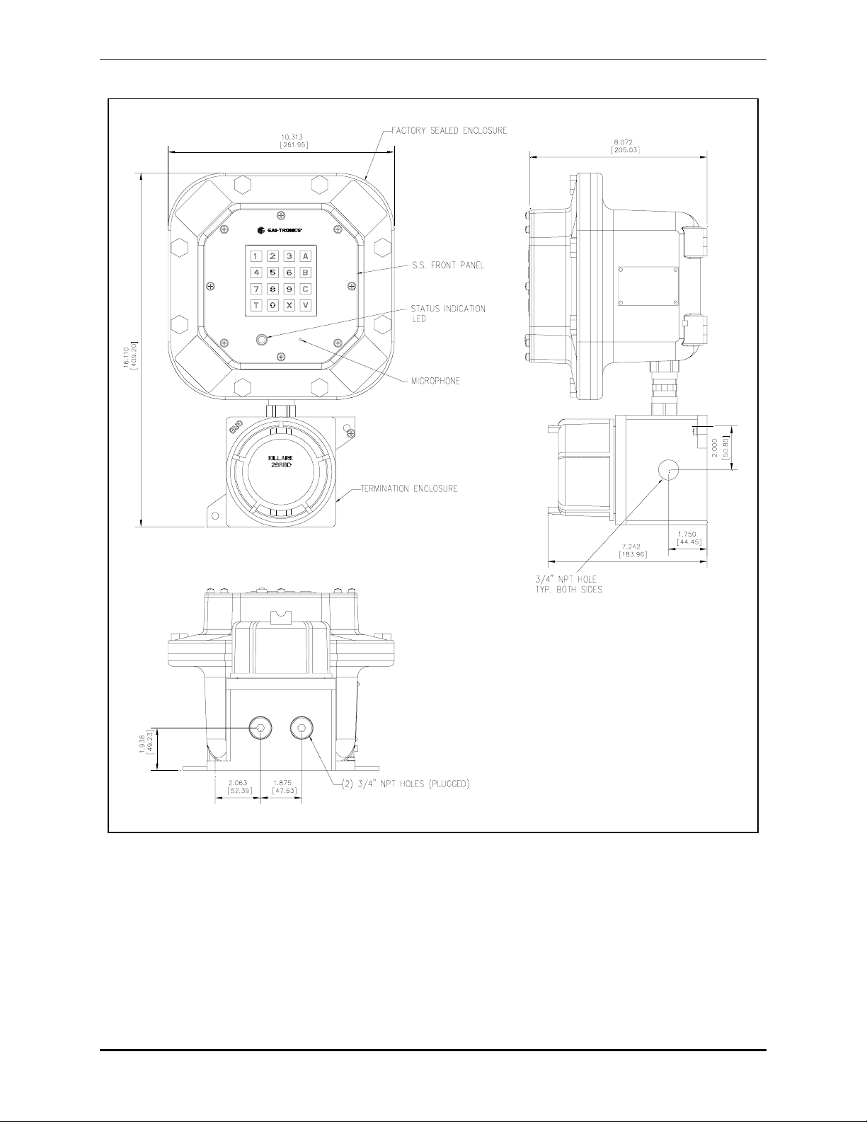
Figure 2. Driller’s Intercom Outline
f:\standard ioms - current release\42004 instr. manuals\42004-679l2d.doc
10/10
Page 6
Pub.: 42004-679L2D
ODEL DEX-10X AND DEX-20X DRILLER’S INTERCOM STATIONS Page 5 of 13
M
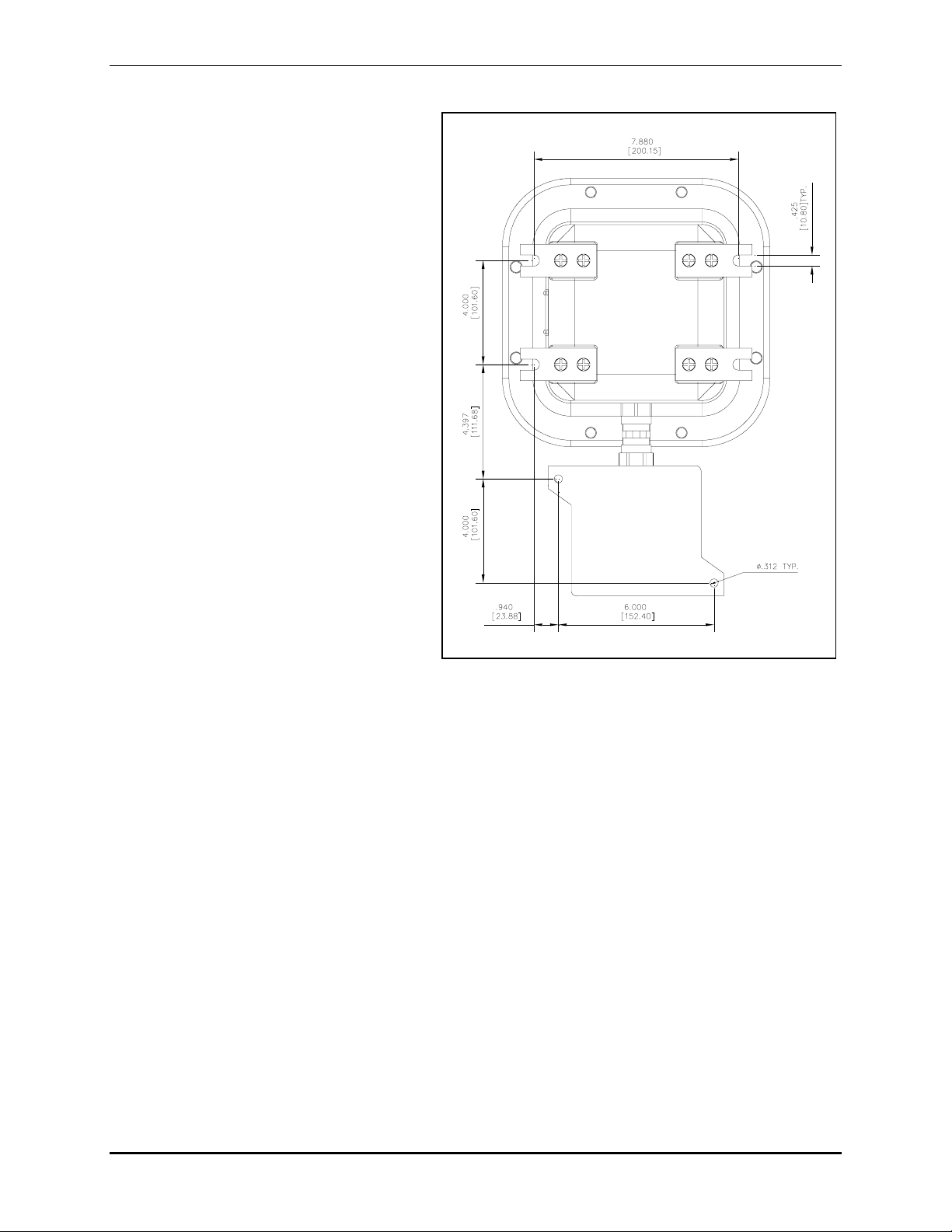
Mounting
The station consists of two enclosures that
are connected by a union. The mounting
location must be a flat, vertical surface that
provides proper clearance, rigidity and
strength to support the station.
The suggested mounting height for stations is
54 inches (137 cm) up to the center of the
factory-sealed enclosure.
To maintain the explosion-proof integrity of
these stations, they are designed with all
mounting hardware located outside the
enclosures. Refer to Figure 3 for mounting
hole and slot dimensions.
Securely fasten the factory-sealed and
termination enclosures to the mounting
location using steel mounting bolts and
washers, or washer-head bolts (hardware not
included).
Conduit Installation
Install the conduit using an approved
electrical conducting-type lubricant on the
threads. The termination enclosure on the
station has one conduit entry on each side
and two on the bottom of the enclosure.
The UL-approved Driller’s Intercom models contain ¾-inch NPT conduit entries. The bottom entries are
plugged from the factory and can be removed to allow use of the entry. Refer to Figure 2 for locations.
All unused conduit openings must be plugged using a close-up plug approved for the specific hazardous
location where the enclosure is used. All conduit connections must meet minimum thread engagements
as specified by the applicable electrical codes.
Figure 3. Rear view showing mounting slots
f:\standard ioms - current release\42004 instr. manuals\42004-679l2d.doc
10/10
Page 7
Pub.: 42004-679L2D
ODEL DEX-10X AND DEX-20X DRILLER’S INTERCOM STATIONS Page 6 of 13
M
Field Wire Installation
Remove the termination enclosure cover and pull all wiring into the termination enclosure. Make all
connections as described below.
N
OTE: All field wiring is to be completed in the termination enclosure (bottom enclosure) only.
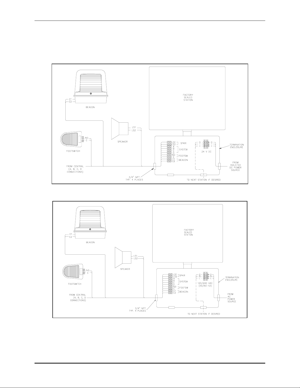
Figure 4. DC Model Installation Diagram (See note below.)
Figure 5. AC Model Installation Diagram (See note below.)
NOTE: Consult the National Electrical Code (NFPA 70), Canadian Standards Association (CSA 22.1),
and local codes for the specific requirements regarding your installation. Install all equipment without
modification and according to the local and national codes. Install conduit and seals where required.
Class 2 circuit wiring must be performed in accordance with NEC 725.55.
f:\standard ioms - current release\42004 instr. manuals\42004-679l2d.doc
10/10
Page 8
Pub.: 42004-679L2D
ODEL DEX-10X AND DEX-20X DRILLER’S INTERCOM STATIONS Page 7 of 13
M
Power
A separate power feed is recommended for stations in Div. 1 areas so that the stations can be de-energized
for maintenance without disrupting the power supply to the other equipment in the Div. 1 area. Refer to
Figure 4 and Figure 5 for wiring details. Remove the termination enclosure cover and pull all wiring into
the termination enclosure. Terminal block TB2 is provided for connection of power to the station.
Terminate all conductor ends using #6-32 screws lugs.
AC Models
Terminate the 120-240 V ac 50/60 Hz feed on TB2. This terminal block can also be used to connect 120240 V ac 50/60 Hz to the next station. The maximum current of the ac feed shall not exceed 20 amperes.
Refer to Figure 5 for more details.
DC Models
Refer to Figure 4. Terminate the 24 V dc feed on TB2. This terminal block can also be used to connect
24 V dc to the next station. The maximum current of the dc feed shall not exceed 20 amperes. Power
must be supplied by an isolated 24 V dc power source. Additional power feeds may be required to
increase the system distance and/or the number of stations.
N
OTE: Isolated dc power sources must be used for this installation. The 24 V dc source should be
located as close to the system center as possible.
Grounding the negative side of the power source at one point is recommended to ensure hum and noisefree operation. Noise present on dc power lines can negatively affect station operation. Therefore, noise
should be limited to 10 mV or less.
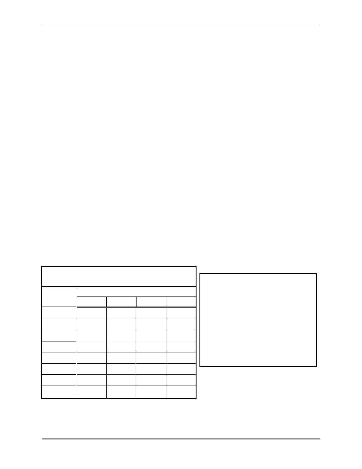
When installing this equipment, the power cable length is an important consideration. Refer to Table 1
for the recommended wire sizing details and the maximum cable lengths. This table is a guideline that is
useful in most applications; however, the installer must take into consideration any parameters specific to
their application.
Table 1. Maximum D istance between
Driller’s Intercom Stations (in feet)* (DC)
*This chart is based on the following
parameters:
# of AWG Wire
Stations 12 14 16 18
1. V(max) = 27 V
2. V(min) = 21 V
1
2
3
4
906 570 358 225
302 190 119 75
151 95 59 37
90 57 35 -------
3. Cable temperature rating = 90º C
4. The American Wire Gauge
resistance table
For V(max) of 24 V, multiply the
distance shown by a factor of 0.47.
5
6
60 38 ------- -------
43 27 ------- -------
7
8
f:\standard ioms - current release\42004 instr. manuals\42004-679l2d.doc
10/10
32 ------- ------- -------
25 ------- ------- -------
Page 9

Pub.: 42004-679L2D
ODEL DEX-10X AND DEX-20X DRILLER’S INTERCOM STATIONS Page 8 of 13
M
Auxiliary Devices
Terminal block TB1 is provided for connection of the speaker, system cable, footswitch, and beacon.
This terminal block accepts a #12-22 AWG wire. Refer to Table 2 for the recommended conductor sizes.
Conductor ends can be stripped and terminated with or without a wire ferrule.
Table 2. Recommended Cable Sizes
Cable Use Size
System Digital: 2-conductor twisted pair, No. 22 AWG is typical
Analog: 4-conductor twisted pair (A/B twist; C/D twist), No. 22 AWG is typical
Power 3-conductor, No. 12 AWG is typical
Beacon 2-conductor, No. 18 AWG is typical (for digital models only)
Footswitch 2-conductor, No. 22 AWG is typical
Speaker Cable 2-conductor twisted pair, No. 18 AWG is typical
1. Install the system cable on TB1 system terminals A-D. Each system cable must be home run to the
Central. Digital stations require termination of a 2-conductor twisted pair cable on system terminals
A and B only. Analog stations require termination of a 4-conductor twisted pair cable (A/B twist &
C/D twist) on system terminals A-D. Refer to Table 3 for the maximum system cable lengths.
Table 3. Maximum System Cable Le ngths
Cable Capacitance 22 AWG 20 AWG 22 AWG 20 AWG
Digital Models Analog Models
30.5 nf/1000 feet 6562 feet 6562 feet 4921 feet 6562 feet
13.7 nf/1000 feet 9843 feet 9843 feet
2. Install the speaker cable on TB1 Speaker terminals LS1 and LS2. Refer to Table 2 for recommended
conductor sizes.
3. Install the beacon control cable on TB1 terminals C1 and C2. This control output is available on
digital stations only. Refer to Table 2 for recommended conductor sizes.
4. Install the footswitch cable on TB1 terminals N.O. and C. Refer to Table 2 for recommended
conductor sizes.
After all connections are made, inspect and clean the machined and threaded surfaces of both the
termination cover and box. Clean the surfaces by wiping with a clean, lint-free cloth. Apply a light coat
of Killark LUBG lubricant to the cover threads. Install and hand-tighten the cover to the box.
f:\standard ioms - current release\42004 instr. manuals\42004-679l2d.doc
10/10
Page 10

Pub.: 42004-679L2D
ODEL DEX-10X AND DEX-20X DRILLER’S INTERCOM STATIONS Page 9 of 13
M
System Interconnection
Refer to Figure 6 for a typical system wiring diagram. Consult the Central Switch manual for further
details on equipment connections to the central switch.
Figure 6. Typical system interconnection diagram
f:\standard ioms - current release\42004 instr. manuals\42004-679l2d.doc
10/10
Page 11

Pub.: 42004-679L2D
ODEL DEX-10X AND DEX-20X DRILLER’S INTERCOM STATIONS Page 10 of 13
M
Operation
The Driller’s Intercom stations can be operated in hands-free, switched-duplex mode when the conditions
permit. If the conditions are not acceptable, the user can switch to simplex mode by depressing the T
button. In some situations (example: high ambient noise levels or stations in close proximity), the station
must be operated in simplex mode at all times.
Digital Models DEX-102 and DEX-202
Intercom Communication Modes
Master Communication - Communication between two stations can be automatically enabled during the
system start-up, or enabled/disabled by the master station.
1. To enable communication depress 6T and the number of the radio channel. To disable
communication depress 6T0. Refer to the “Listening to the Radio Channel” section of the Central
Switch manual for more details.
OTE: The associated slave station must be configured to transmit to the radio channel.
N
2. The LED on the front panel illuminates to indicate a call is in progress.
N
OTE: For digital stations only, the beacon output can be activated for a variety of conditions. Refer
to the “Attendant Contacts” section of the Central Switch manual for details.
3. Depress and hold the T button or the footswitch and speak into the microphone to transmit audio.
4. Audio from the slave station is broadcast over this station’s speaker when the T button or footswitch
is released.
Point-to-Point Communication – Refer to the “Direct Dialing” section of the Central Switch manual for
additional details.
1. Enable point-to-point communication by dialing the extension of the desired station, or by entering
the direct dial button(s) sequence.
2. The LED on the front panel illuminates to indicate a call is in progress.
OTE: For digital stations only, the beacon output can be activated for a variety of conditions. Refer
N
to the “Attendant Contacts” section of the Central Switch manual for details.
3. Speak into the microphone to transmit audio. (If necessary, talk/listen control from this station can be
controlled using the T button on the keypad or by using the station’s footswitch input.)
4. Audio is broadcast over this station’s speaker when the other station user speaks. (If necessary,
talk/listen control from the other station can be controlled using the T button on the keypad or by
using the station’s footswitch input.)
5. Terminate the call by depressing the X button.
Volume Control
The master volume level adjustments for this station can be configured in the Central. Refer to the
“Volume Configuration” section of the Central Switch manual for details.
During an active call, the speaker volume can be increased or decreased. Increase the volume by
simultaneously depressing the V and B buttons. Decrease the volume by simultaneously depressing the V
and C buttons. The volume level setting range is between 0 and 9, and the volume setting is reset when
the call is terminated.
f:\standard ioms - current release\42004 instr. manuals\42004-679l2d.doc
10/10
Page 12

Pub.: 42004-679L2D
ODEL DEX-10X AND DEX-20X DRILLER’S INTERCOM STATIONS Page 11 of 13
M
Paging
This station is capable of sending and receiving all-calls and group calls. Refer to the “All-Call” and
“Group Call” sections of the Central Switch manual for configuration details.
Alarms and Music
This station is capable of receiving alarms and music. Refer to the “Alarm” and “Music” sections of the
Central Switch manual for configuration details.
Analog Models DEX-101 and DEX-201
Intercom Communication Modes
Slave Communication - Communication between two stations can be automatically enabled during the
system start-up, or when enabled/disabled by the master station.
1. The LED on the front panel illuminates to indicate a call is in progress.
OTE: The beacon output control is not available on this model.
N
2. Speak into the microphone to transmit audio.
3. Audio is broadcast over this station’s speaker when the master station user pushes the T button.
Point-to-Point Communication - Communication with this station can be enabled when another station
dials the extension of this station.
1. The LED on the front panel illuminates to indicate a call is in progress.
OTE: The beacon output control is not available on this model.
N
2. Speak into the microphone to transmit audio. If necessary, talk/listen control from this station can be
controlled using the station’s footswitch input.
3. Audio is broadcast over this station’s speaker when the other station user speaks. (If necessary,
talk/listen control from the other station can be controlled using the T button on the keypad or by
using the station’s footswitch input.)
4. The calling station must terminate the call by depressing the X button.
Volume Control
Volume level adjustments for this station can be configured in the Central. Refer to the “Volume
Configuration” section of the Central Switch manual for details.
Paging
This station is capable of sending and receiving all-calls and group calls. Refer to the “All-Call” and
“Group Call” sections of the Central Switch manual for configuration details.
Alarms and Music
This station is capable of receiving alarms and music. Refer to the “Alarm” and “Music” sections of the
Central Switch manual for configuration details.
f:\standard ioms - current release\42004 instr. manuals\42004-679l2d.doc
10/10
Page 13

Pub.: 42004-679L2D
ODEL DEX-10X AND DEX-20X DRILLER’S INTERCOM STATIONS Page 12 of 13
M
Maintenance
General Information
If you experience additional problems, please contact the GAI-Tronics Field Service Department at
1-800-492-1212 and follow the voice prompts.
In order to ensure explosion-proof integrity, repairs to this equipment are to be made ONLY by the
GAI-Tronics Field Service Department and/or factory-authorized personnel. Factory-authorized
personnel must reseal the unit by first checking that all flange surfaces are free of gouges or
scratches. Apply a light coating of Killark “LUBG” lubricant to all flanged surfaces before closing.
Install the bolts and tighten to 30 ft-lbs.
WARNING
Always remove power to this station and any associated equipment before beginning any
maintenance.
Troubleshooting
Problem Possible Solution
Low speaker volume Increase the actual and/or maximum volume settings in the configuration.
Refer to the “Volume Configuration” section of the Central Manual for
details.
High speaker volume Decrease the actual and/or maximum volume settings in the configuration.
Refer to the “Volume Configuration” section of the Central Manual for
details.
No speaker output Set the station’s attendant contacts OUT 1 to be active while the conversation
is active and when the loudspeaker is active. Refer to the “Attendant
Contacts Configuration” section of the Central Manual for details.
No beacon contact Verify the station’s Attendant Contacts OUT 2 are active for the desired
condition. Refer to the “Attendant Contacts Configuration” section of the
Central Switch manual for details.
Feedback 1. Point the station speakers in opposite directions.
2. Reduce the speaker volume of the stations. Refer to the “Volume
Configuration” section of the Central Switch manual for details.
3. Increase the distance between stations.
4. Change the mode of operation from duplex to simplex. Refer to the
“Simplex Configuration” section of the Central Switch manual for details.
5. Two stations can be barred from communication. Refer to the
“Protection against Feedback Configuration” section of the Central
Switch manual for details.
f:\standard ioms - current release\42004 instr. manuals\42004-679l2d.doc
10/10
Page 14

Pub.: 42004-679L2D
ODEL DEX-10X AND DEX-20X DRILLER’S INTERCOM STATIONS Page 13 of 13
M
Specification s
Power input (120 V ac)....... Voltage ............................................................. 108/132 V ac range, 50/60 Hz
Power consumed .................................................... 23 VA, 10 watts (nominal)
52 VA, 50 watts (maximum)
Power input (240 V ac)....... Voltage ............................................................. 216/264 V ac range, 50/60 Hz
Power consumed .................................................... 43 VA, 11 watts (nominal)
63 VA, 50 watts (maximum)
Power input (24 V dc)......... Voltage.................................................................................. 21/27 V dc range
Power consumed ................................................................ 42 watts (nominal)
50 watts (maximum)
Construction finish.............. Enclosure........................... Gray powder epoxy/polyester on exterior surfaces
Front panel................................................................. Passivated stainless steel
Microphone amplifier ......... Frequency response.................................. 200–4,000 Hz, ±3 dB ref. @ 1 kHz
Speaker amplifier................ Output...... Class AB, 18 watts min. into 8 ohms, with nominal supply voltage
Frequency response................................ 200–10,000 Hz, ±3 dB ref. @ 1 kHz
Distortion.................................................... 1% max. THD @ 1 kHz, 18 watts
Loudspeaker............................................................................................................................... 8 or 16 ohms
Inputs .............................................................................................................. 16-button keypad, footswitch,
speaker volume adjustment (adjusted through keypad)
Outputs................................ Call Indication LED ..........................................................................................
Beacon Control (digital only)............................................ 30 V @ 3 A (max.)
System cabling.................... Digital................................................................. Star-feed, 2-wire twisted pair
Analog ................................................................ Star-feed, 4-wire twisted pair
Temperature range ................................................................Analog: −13º F to + 149º F (-25º C to +65º C)
Digital: -4º F to + 140º F (-20º C to +60º C)
Dimensions ........................................................ 10.31 W × 16.11 H × 8.07 D (262.0 × 409.2 × 205.0 mm)
Shipping weight ....................................................................................................................39 lbs. (17.7 kg)
Approvals
UL ........................................................................................................... NRTL Listed for USA and Canada
Class I, Div. 1 & 2, Groups C & D T4
Class I, Zones 1 & 2, Group IIB & IIA
Class II, Div. 1 & 2, Groups E, F, & G
Class III, Div. 1 & 2, Type 4X
f:\standard ioms - current release\42004 instr. manuals\42004-679l2d.doc
10/10
 Loading...