

Page 1

Pub. 42004-146H
GAI-TRONICS® CORPORATION
A HUBBELL COMPANY
Model 295F and 295W
Clean Phone™ Telephone
Confidentiality Notice
This manual is provided solely as an operational, installation, and maintenance guide and contains
sensitive business and technical information that is confidential and proprietary to GAI-Tronics. GAITronics retains all intellectual property and other rights in or to the information contained herein, and
such information may only be used in connection with the operation of your GAI-Tronics product or
system. This manual may not be disclosed in any form, in whole or in part, directly or indirectly, to any
third party.
General Information
The GAI-Tronics Model 295F Flush-Mount and Model 295W Wall-Mount Clean Phone™ Telephones
are designed for the exacting requirements of clean rooms. They are constructed of stainless steel and
have a completely smooth polyester front panel that will not trap particulate matter. Calls are made by
pressing one of the two auto-dial buttons or by using the fully functional keypad. The Flash button
allows the phone to use the features of a PBX system. The oversized, clearly labeled buttons allow for
easy operation with gloved hands.
Auto-Dial Buttons
The Model 295 Clean Phones feature two auto-dial buttons to store frequently dialed telephone numbers.
If using the auto-dial feature, it is important to program the Auto-dial Time Delay option, which sets the
amount of time lapse between the auto-dial button press and the actual dialing operation. The default
time period of ten seconds could be too long if the feature is to be used for emergency communication.
This feature is fully explained in the Programming Information section.
Auto-Answer
The Model 295 also offers a programmable activation/deactivation of the Auto-answer feature. When
activated, this feature determines how many rings must elapse before auto-answering. The Auto-answer
feature allows the telephone to go off-hook automatically so technicians do not have to leave their work
stations to answer the telephone.
A light under the ON portion of the ON/OFF button is activated to indicate if the telephone is off-hook.
If the Auto-answer feature is not activated, the telephone will not go off hook until someone actually
touches the ON/OFF button.
GAI-Tronics Corporation P.O. Box 1060, Reading, PA 19607-1060 USA
610-777-1374 800-492-1212 Fax: 610-796-5954
V
ISIT WWW.GAI-TRONICS.COM FOR PRODUCT LITERATURE AND MANUALS
Page 2

Pub. 42004-146H
Model 295F and 295W Clean Phone™ Telephone Page:
2 of 17
Local or Remote Programming
The Model 295 can be programmed locally or remotely using another DTMF telephone. The
programming mode, whether local or remote, must be entered through a series of button presses.
N
OTE: The local programming password is factory-programmed as # 1 2 3 and cannot be changed.
The remote password is factory-programmed as 0 2 9 5, but can be changed to any four-digit number
using the programming instructions provided.
Model 295 can also be programmed to use either a long (350 ms) or short (50 ms) called-party loop
current disconnect mode. Determine your system configuration before completing this sequence.
Touch-Tone or Pulse Dialing
The Model 295 can be programmed for touch-tone (also known as dual-tone multifrequency [DTMF]) or
pulse dialing. To determine what kind of dialing you require, contact your local telephone company.
Safety Guidelines
When installing any GAI-Tronics telephone equipment, please adhere to the following guidelines to
ensure the safety of all personnel:
• NEVER install telephone wiring during a lightning storm.
• NEVER install telephone jacks in wet locations unless the jack is specifically designed for wet
locations.
• NEVER touch uninsulated telephone wires or terminals unless the telephone line has been
disconnected at the network interface.
• USE CAUTION when installing or modifying telephone lines.
If you have any questions, please call our toll-free number: 800-492-1212
d:\standard ioms - current release\42004 instr. manuals\42004-146h.doc
11/05
Page 3

Pub. 42004-146H
Model 295F and 295W Clean Phone™ Telephone Page:
3 of 17
Installation
Feedback problems can be avoided by installing each clean telephone in a separate room and wall.
Model 295F Mounting and Wiring
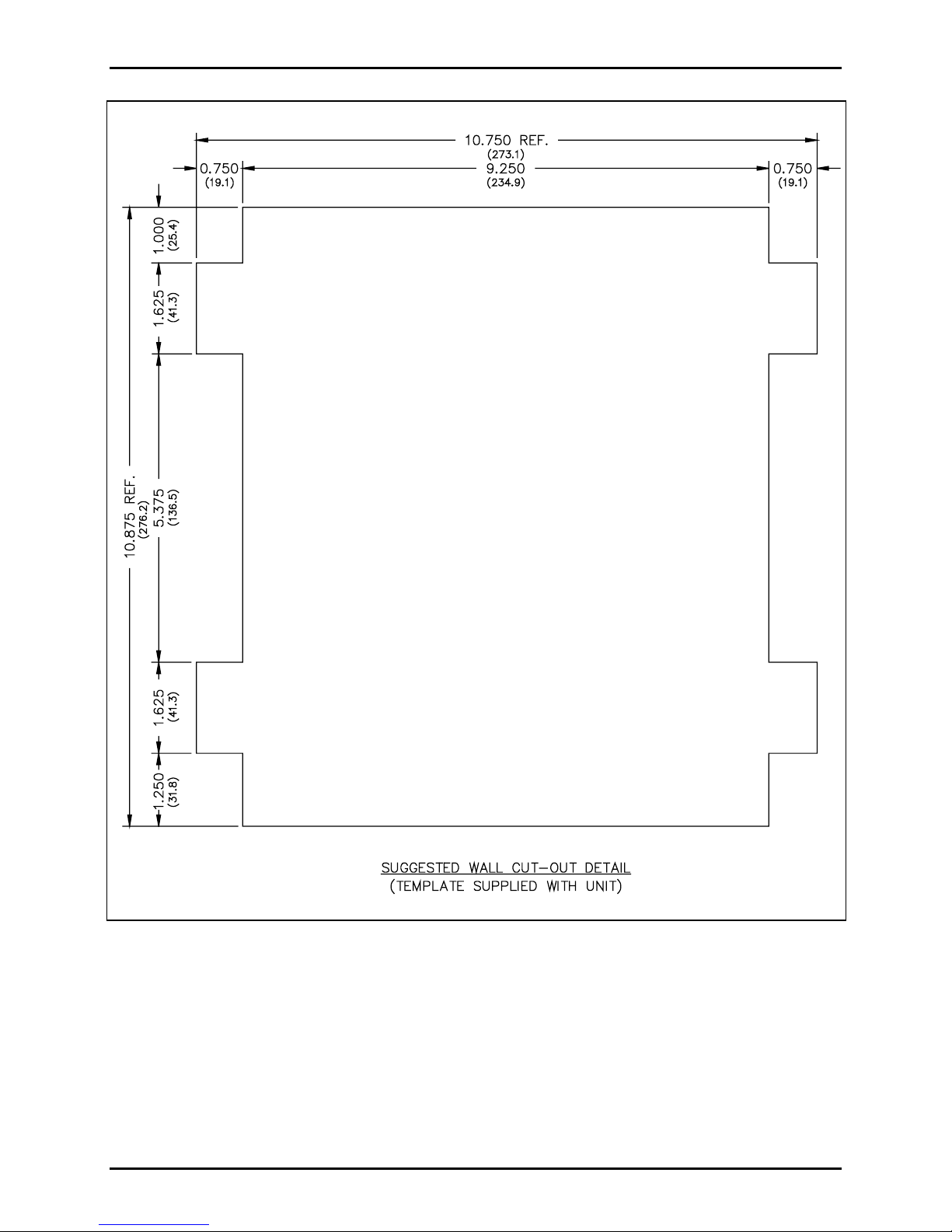
1. Refer to Figure 6 on page 17 for a drilling template.
2. Use the template dimensions as a guide to mark the wall, and make the required cuts.
3. Place the back bracket in the wall. Locate the mounting holes.
4. Drill two holes in the lower right corner and the upper left corner, to secure the bracket. Drill the rest
of the holes you intend to use, and secure the remaining holes.
5. Feed the wiring through the supplied bushing.
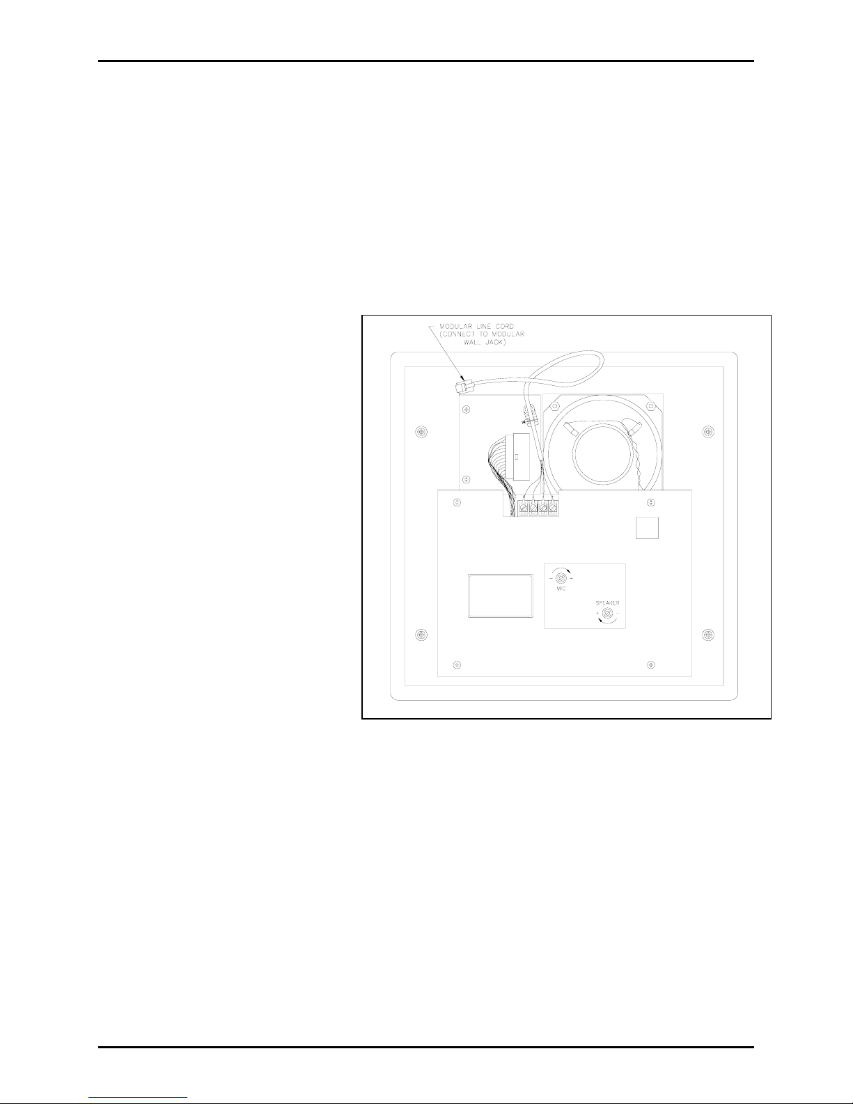
6. Snap the cover off of the modular wall jack. Refer to Figure 1 as a wiring guide. Wire the incoming
tip wire to the green wire of the modular jack. Wire the incoming ring wire to the red wire of the
modular jack, the (COM) wire to the yellow wire of the modular jack, and (-48 V) wire to the black
wire of the modular jack.
Figure 1. Modular Wall Jack Wiring for Model 295F
d:\standard ioms - current release\42004 instr. manuals\42004-146h.doc
11/05
Page 4

Pub. 42004-146H
Model 295F and 295W Clean Phone™ Telephone Page:
4 of 17
7. Replace the modular jack cover. Plug the modular connector from the front panel assembly into the
modular wall jack. Take the front panel of the clean telephone and align it with four slots in the
mounting bracket.
8. Using the pressure points shown in Figure 2, push the panel firmly in and then down.
Figure 2. Front panel with pressure points shown
d:\standard ioms - current release\42004 instr. manuals\42004-146h.doc
11/05
Page 5

Pub. 42004-146H
Model 295F and 295W Clean Phone™ Telephone Page:
5 of 17
Model 295W Mounting and Wiring
1. Position the back box on the wall, making sure the box is level. Drill the two corner holes in the
upper left and lower right, and secure it with the screws.
2. Drill the remaining holes, and secure the remaining screws.
3. Feed the wires through the bushing.
4. Snap the cover off the modular wall jack. Refer to Figure 3. Wire the incoming tip wire to the green
wire in the modular jack, the incoming ring wire to the red wire in the modular jack, the (COM) wire
to the yellow wire, and the (-48 V) wire to the black wire. DO NOT REMOVE the blue and white
wires. Replace the modular wall jack cover.
5. Plug the modular connector from the front panel assembly into the modular wall jack.
6. Take the front panel of the clean telephone and align it with the four slots in the mounting bracket.
7. Using the pressure point shown in Figure 2, push the panel firmly in and then down.
d:\standard ioms - current release\42004 instr. manuals\42004-146h.doc
11/05
Figure 3. Mounting the Model 295W
Page 6

Pub. 42004-146H
Model 295F and 295W Clean Phone™ Telephone Page:
6 of 17
Pow er and Wiring Information (Le v el C Po wer)
The Model 295F and 295W Clean Phones are powered from a 48 V dc @ 250 mA power supply. The
power supply should be Nationally-Recognized Testing Laboratory (NRTL) listed per UL specification
UL 1012 or equivalent.
If these clean telephones are powered through the black and yellow “spare pair” in the telephone cable,
the power to these wires must be limited to UL Level C power. To meet the requirements for Level C
power, the current to the telephone must be limited to 1 ampere maximum at 48 V dc.
The GAI-Tronics Model 237 Power Supply is a 48 V dc @ 250 mA UL listed power supply that can be
used to power a single Model 295 Clean Phone. See Figure 4 for wiring details for the Model 237 Power
Supply.
The distance between a telephone and the 48 V dc power source is limited only by the maximum
allowable wire resistance, (32 ohms). See the table for calculated distances for standard wire sizes.
Calculated Distance for Standard Wire Sizes
AWG Feet Meters Miles
24 620 190 0.11
22 985 300 0.18
20 1585 480 0.30
19 1985 605 0.37
18 2500 760 0.47
16 3980 1210 0.75
14 6350 1935 1.2
Refer to the table provided above. When using 24 AWG wire, the 48 V dc power source can be located
up to 620 feet, 190 meters, or 0.11 miles away from the phone. Paralleling pairs of the same gauge wire
will increase operating distance by a factor of two.
d:\standard ioms - current release\42004 instr. manuals\42004-146h.doc
11/05
Figure 4. Model 237 Power Supply Wiring
Page 7
Pub. 42004-146H
Model 295F and 295W Clean Phone™ Telephone Page:
7 of 17
Microphone Sensitivity and Speaker V olume Adjustment
The speaker volume and microphone sensitivity controls are factory-set to a nominal value. This value
may not be suitable for the particular noise environment where Model 295 phone is to be installed. To
obtain the best performance possible in your particular area, we recommend that the following adjustment
procedure be performed after Model 295 is installed in its final location and in typical ambient noise
conditions. You will need a small standard screwdriver for the adjustments.
1. Remove the unit from its wall mounting, but do not unplug it.
2. Call someone, or have someone call you from a handset type telephone. They should be outside your
location and should read a few paragraphs of text.
3. See Figure 5. While they are
reading, locate the MIC adjustment
on the rear of the unit, and turn it
counterclockwise until it is all the
way down.
4. Locate the SPEAKER adjustment.
Turn it until the speaker volume is
set to a level that the person talking
can be comfortably understood
when you are a few feet from the
telephone.
5. Turn the MIC adjustment clockwise
until the speaker starts to “cut out”
the speech from the person
talking—when it sounds like the
first syllable of every word is
missing.
6. Back the MIC adjustment off until
the speech comes back to normal
but no farther. This adjustment
should require only an eighth to a
quarter turn in the counter-
Figure 5. Microphone and Speaker Adjustments
clockwise direction.
7. Try a test conversation on the line. If the quality of communication is unsatisfactory, begin with Step
1 of this section, and readjust Model 295.
Model 295 is now fully adjusted for the acoustics and noise conditions within your area.
d:\standard ioms - current release\42004 instr. manuals\42004-146h.doc
11/05
Page 8

Pub. 42004-146H
Model 295F and 295W Clean Phone™ Telephone Page:
8 of 17
Programming Information
The GAI-Tronics Model 295 Clean Phone is programmable. There are a number of features that can be
customized, or you may use the factory settings (defaults).
The programmable features include setting the auto-dial numbers, setting the auto-dial time delay, setting
the number of rings before Model 295 automatically answers, selecting DTMF or pulse dialing, and
selecting the remote programming password.
Model 295 Clean Phone can be programmed in two ways—local and remote. The front panel of the
Model 295 Clean Phone is used for local programming with the local password. To program the unit
remotely, you must call the Model 295 Clean Phone, and enter the password (from a DTMF phone).
Programming the unit is the same whether the programming mode is entered locally or remotely except
that each mode has its own unique password. The unit must be in the programming mode before
attempting to program any functions. After each programming key sequence, either a confirmation tone
(a single beep) or an error tone (a high-low tone) will sound. A confirmation tone indicates the command
was accepted, and that the new input has been saved. Any fully completed programming sequence is
saved in the permanent memory. If, however, you begin programming a function, and do not complete all
the steps, it will not be saved, and all the information for that function must be re-entered.
The Programming Table lists the programmable functions on the Model 295 Clean Phone and the input
codes for each of these functions. The table also lists the defaults (factory settings).
d:\standard ioms - current release\42004 instr. manuals\42004-146h.doc
11/05
Page 9

Pub. 42004-146H
Model 295F and 295W Clean Phone™ Telephone Page:
9 of 17
Local Programming
Entering the Local Programming Mode
To program the Model 295 Clean Phone locally, you must enter the local programming password, which
is fixed and cannot be changed. Enter the key sequence # 1 2
The unit will emit a high pitch beep for each correct key pressed. The light under the front panel
ON/OFF button will begin blinking at a slow rate to indicate the programming mode has been entered. If
an incorrect key is pressed, you will hear a single low pitch beep to warn that the password is incorrect.
Following the correct entry of the local programming password, the unit is in a programming mode where
the user may program the unit as desired. For programming instructions, see the Programming Table.
Each digit of the local programming password must be entered within 5 seconds of the one before it. If a
digit is not entered within the 5-second limit, the unit will emit a single low pitch beep and exit the local
programming mode. If the unit times out waiting for the password, or if the password entered incorrectly,
the unit will automatically exit the local programming mode.
The unit will ignore any incoming calls when in the local programming mode.
Exiting the Local Programming Mode
3 to access the local programming mode.
There are two ways to exit the local program mode:
• If there is no keypad activity for 20 seconds, the unit automatically exits the local program mode.
• The user can terminate the mode at any time by pressing the ON/OFF button.
• The unit will emit a short low pitch beep and turn off the light under the ON/OFF button
d:\standard ioms - current release\42004 instr. manuals\42004-146h.doc
11/05
Page 10

Pub. 42004-146H
Model 295F and 295W Clean Phone™ Telephone Page:
10 of 17
Remote Programming
Entering the Remote Programming Mode
Using a DTMF telephone, dial the unit’s telephone number, wait for an answer tone, and enter the unit’s
password. If you have not changed the password, enter 0
first, it allows Model 295 to be programmed from any DTMF telephone, and second, permits only
authorized personnel (those informed of the password) to reprogram the unit. If there is a security leak,
the password can be updated in a matter of seconds. The password can be changed through local or
remote programming.
The unit will answer the call (following the programmed number of rings), then send a short tone (answer
tone). The password must be entered within two seconds of hearing the answer tone. The remote
programming mode can only be entered when the entire password has been entered in the allotted time.
The unit will immediately hang up (disconnect) if the password is entered incorrectly. Failure to begin
entering the password after the answer tone will result in an intercom call.
The front panel light under the ON button will blink slowly, indicating that the unit is in the programming
mode. All front panel keys and incoming calls are ignored during the remote programming mode.
Exiting the Remote Programming Mode
2 9 5. The password provides two benefits—
There are three ways to exit the remote programming mode:
• The unit detects the caller has hung up.
• The caller enters * for at least two seconds.
• The unit times out waiting for a digit (20 seconds).
In any event, the unit will go on-hook and extinguish the light under the ON button.
d:\standard ioms - current release\42004 instr. manuals\42004-146h.doc
11/05
Page 11
Pub. 42004-146H
Model 295F and 295W Clean Phone™ Telephone Page:
11 of 17
Programming Instructions
Before you begin programming, determine whether you will be programming locally or remotely. This
way, you can be clear on the steps you will take and the passwords you will need to complete the
programming.
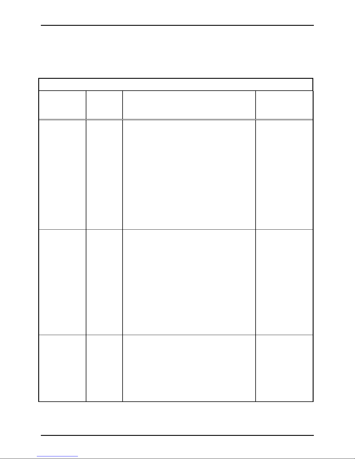
Programming Table
Key
Function
Sequence
Description Default
Settings
Reset the unit
to the factory
codes
(Defaults)
Input the
telephone
numbers for
one or both
auto-dial
buttons
#00 Resets the unit to the codes programmed at the
GAI-Tronics factory.
DD…*N Assigns a user-supplied telephone number to
either auto-dial button. DD… represents the
user-supplied telephone number, which can be up
to 16 digits in length. N represents the desired
auto-dial button number (1 or 2).
To store * or #, enter the digits twice in
succession. To force the unit to wait for a second
dial tone, enter *# in the appropriate place in the
dialing sequence.
For Example: To assign the police emergency
number 911 to Auto-dial 1, enter 911*1.
If you must dial 9 to get an outside line, using
the above example, enter 9*#911*1.
• No auto-dial 1
number;
• No auto-dial 2
number;
• Auto-answer
after 3 rings;
• Remote
password
0 2 9 5;
• DTMF dialing;
• Dial-tone
disconnect
disabled
No numbers
Set the auto-
#100N The auto-dial delay time is the amount of time
dial delay time
d:\standard ioms - current release\42004 instr. manuals\42004-146h.doc
11/05
the unit waits before dialing the programmed
telephone number for the auto-dial feature.
Available time delay options are 2 through 9
seconds.
OTE: A three-second auto-dial delay time is
N
recommended. For Example: For a three-second
auto-dial delay time, enter
#1003.
10 seconds
Page 12

Pub. 42004-146H
Model 295F and 295W Clean Phone™ Telephone Page:
Programming Table
Key
Function
Sequence
Description Default
Settings
12 of 17
Store the unit’s
remote
programming
password
Set the autoanswer feature
Store the
dialing mode
#14DDDD This password must be supplied to remotely
program Model 295. The length is four digits.
For Example: To program the password 1234,
enter #141234.
#15D Programs Model 295 to automatically answer
after D rings, where D is a DTMF digit from 1 to
9. To deactivate the auto-answer mode, so that
the telephone must be manually answered, enter
0. Model 295 will sound a “telephone ring” on
the speaker to announce an incoming call.
For Example:
To set the unit to auto-answer after 5 rings, enter
#155.
To deactivate the Auto-answer feature, where the
ON button on the telephone must be pressed to
answer the call, enter #150.
#20L This option selects either DTMF or pulse dialing
mode. To dial using DTMF, L = 1. To dial
using pulse mode, L = 0.
To program DTMF, enter #201.
0 2 9 5
3
1 (DTMF)
Store the
called-party
loop current
disconnect
mode
To program pulse, enter #200.
#21L This option selects either of the two loop current
disconnect periods for a call to Model 295.
Determine your system configuration before
completing this sequence.
To program the long disconnect, L = 1.
To program the short disconnect, L = 0.
To program the long disconnect, enter #211.
To program the short disconnect, enter
#210.
1 (Long)
d:\standard ioms - current release\42004 instr. manuals\42004-146h.doc
11/05
Page 13

Pub. 42004-146H
Model 295F and 295W Clean Phone™ Telephone Page:
Programming Table
Key
Function
Sequence
Description Default
Settings
13 of 17
Activate/
deactivate the
dial tone
disconnect
mode
#22L This option activates/deactivates the Dial Tone
Disconnect function. If activated, Model 295
disconnects after sensing a dial tone for ten
seconds.
If deactivated, Model 295 remains off-hook until
someone presses the ON/OFF button.
To activate the Dial Tone Disconnect feature,
L = 1.
To deactivate the Dial Tone Disconnect feature,
L = 0.
To activate the Dial Tone Disconnect feature,
enter #221.
To deactivate the Dial Tone Disconnect feature,
enter #220.
WARNING
Some environments will inhibit the
performance of the Dial Tone Disconnect
feature.
We cannot guarantee that all customers can
reliably make use of this feature. Use this feature
only if no other disconnect options are available.
0 (disabled)
Table Key
D = digit 0-9 N = 1 or 2; or digit 0-9
L = 0-Disable, 1-Enable
d:\standard ioms - current release\42004 instr. manuals\42004-146h.doc
11/05
Page 14

Pub. 42004-146H
Model 295F and 295W Clean Phone™ Telephone Page:
14 of 17
Operating Instructions
Incoming Calls
The clean telephone can be programmed to operate in two different modes: auto-answer and conventional
answer.
To answer an incoming call at a clean telephone programmed to operate conventionally, press the
ON/OFF button on the front panel of the telephone. The indicator light will go on when the call has been
successfully connected. Press the ON/OFF button to disconnect and end the conversation.
To answer an incoming call at a clean telephone programmed to operate in the auto-answer mode, do
nothing. The telephone will automatically answer the call after the programmed number of rings. The
call will then be connected, and conversation can take place as normal. Once the line is established, the
indicator light on the front panel will light. The telephone line can be disconnected several different
ways. See the Programming Information section for details on call termination.
Outgoing Calls
To place a call from the clean telephone, simply press the ON/OFF button on the front panel, and dial the
desired number. The call is connected as with any conventional telephone. To disconnect the call, press
the ON/OFF button.
When programming and/or making test calls to emergency numbers, remain on the line, and briefly
explain to the dispatcher the reason for the call. Perform such activities in the off-peak hours, such as
early morning or late evenings.
Conv ersing
The clean telephone is designed to operate in a variety of environments with different noise levels. The
speaker volume and microphone sensitivity are set as part of the installation procedure. Depending on the
level settings of these two parameters, the ideal distance from which to speak into the clean telephone
may vary. The person speaking into the telephone should stand approximately 3 feet from the unit
although the distance can vary and should be determined through trial and error in your setting.
In general, it is not advisable to yell or talk loudly when speaking through the clean telephone. The
design of the unit takes background noise into consideration. Only in the loudest environments will it be
necessary to speak in a louder voice. In most situations, yelling will only degrade the quality of your
conversation.
d:\standard ioms - current release\42004 instr. manuals\42004-146h.doc
11/05
Page 15

Pub. 42004-146H
Model 295F and 295W Clean Phone™ Telephone Page:
15 of 17
User Instructions
Federal Communication Commission (FCC) regulations require that these guidelines be followed:
This equipment complies with Part 68 of the FCC Rules. On the rear of the unit is a label that contains,
among other information, the FCC Registration Number and Ringer Equivalence Number (REN) for this
equipment. If requested, this information must be given to the telephone company.
The REN is used to determine the quantity of devices that may be connected to the telephone line.
Excessive RENs on the telephone line may result in devices not ringing in response to an incoming call.
In most, but not all areas, the sum of the RENs should not exceed five (5.0). To be certain of the number
of devices that may be connected to the line, contact the telephone company to find out the maximum
RENs for the calling area.
If your telephone equipment causes harm to the telephone network, the telephone company may
discontinue service temporarily. If possible, they will notify you in advance. If advance notice is not
practical, you will be notified as soon as possible. You will be informed of your right to file a complaint
with the FCC.
The telephone company may make changes in its facilities, equipment, operations, or procedures that
could affect the operation of the equipment. If this happens, the telephone company will provide advance
notice for you to make the necessary modifications to maintain uninterrupted service.
If trouble is experienced with this equipment, please contact GAI-Tronics at 800-492-1212 inside the
USA or 610-777-1374 outside the USA, for repair and/or warranty information. If the trouble is causing
harm to the telephone network, the telephone company may request you remove the equipment from the
network until the problem is resolved.
This equipment uses the RJ11C USOC jack.
This equipment cannot be used on telephone company-provided coin service. Connection to party-line
service is subject to state tariffs.
d:\standard ioms - current release\42004 instr. manuals\42004-146h.doc
11/05
Page 16
Pub. 42004-146H
Model 295F and 295W Clean Phone™ Telephone Page:
16 of 17
Specifications
Power input......................................................................................................................... 48 V dc, 250 mA
USOC.................................................................................................................................................. RJ11C
Signaling..................................................................................................... DTMF or pulse (programmable)
FCC Registration Number ...................................................................................... ADGUSA-60747-MT-E
Ringer Equivalence Number (REN)....................................................................................................... 0.4B
Speaker output ....................................................... 85 dBA spl @ 1 meter, full volume (max. speech level)
Operating temperature............................................................................ -20° C to +60° C (-4° F to+140° F)
Model 295F
Construction......................................................................... Front panel: tactile, polyester membrane panel
Mounting bracket: 16-gauge stainless steel
Dimensions .............................................................. Front panel: 12 W × 12 H inches; (304.8 × 304.8 mm)
Mounting bracket: 10.75 W × 10.875 H × 1.75 D inches; (273.1 × 276.2 × 44.3 mm)
Weight................................................................................................................................................ 5.25 lbs
Model 295W
Construction......................................................................... Front panel: tactile, polyester membrane panel
Mounting bracket: 16-gauge stainless steel
Dimensions ............................................................... Front panel: 12 W × 12 H inches (304.8 × 304.8 mm)
Back enclosure: 12 W × 12 H × 2.06 D inches (304.8 × 304.8 × 52.3 mm)
Weight................................................................................................................................................ 5.25 lbs
Replacement Parts
The following list details the replacement parts available for the Model 295 Clean Phone. Please use
reference number when ordering.
Part Number Description
12518-002 PCBA Replacement Kit
12575-001 Front Panel Replacement Kit
12585-001 Speaker Assembly Kit
14560-002 Mounting Bracket (Model 295F only)
14560-005 Rear Enclosure (Model 295W only)
d:\standard ioms - current release\42004 instr. manuals\42004-146h.doc
11/05
Page 17
Pub. 42004-146H
Model 295F and 295W Clean Phone™ Telephone Page:
17 of 17
d:\standard ioms - current release\42004 instr. manuals\42004-146h.doc
11/05
Figure 6. Drilling Template
Page 18

Warranty
Equipment. GAI-Tronics warrants for a period of one (1) year from the date of shipment, that any
GAI-Tronics equipment supplied hereunder shall be free of defects in material and workmanship, shall
comply with the then-current product specifications and product literature, and if applicable, shall be fit
for the purpose specified in the agreed upon quotation or proposal document. If (a) Seller’s goods prove
to be defective in workmanship and/or material under normal and proper usage, or unfit for the purpose
specified and agreed upon, and (b) Buyer’s claim is made within the warranty period set forth above,
Buyer may return such goods to GAI-Tronics nearest depot repair facility, freight prepaid, at which time
they will be repaired or replaced, at Seller’s option, without charge to Buyer. Repair or replacement shall
be Buyer’s sole and exclusive remedy, and the warranty period on any repaired or replacement equipment
shall be one (1) year from the date the original equipment was shipped. In no event shall GAI-Tronics
warranty obligations with respect to equipment exceed 100% of the total cost of the equipment supplied
hereunder. Buyer may also be entitled to the manufacturer’s warranty on any third-party goods supplied
by GAI-Tronics hereunder. The applicability of any such third-party warranty will be determined by
GAI-Tronics.
Services. Any services GAI-Tronics provides hereunder, whether directly or through subcontractors,
shall be performed in accordance with the standard of care with which such services are normally
provided in the industry. If the services fail to meet the applicable industry standard, GAI-Tronics will,
for a period of one (1) year from the date of completion, re-perform such services at no cost to Buyer. Reperformance of services shall be Buyer’s sole and exclusive remedy, and in no event shall GAI-Tronics
warranty obligations with respect to services exceed 100% of the total cost of services provided
hereunder.
Warranty Periods. Every claim by Buyer alleging a defect in the goods and/or services provided
hereunder shall be deemed waived unless such claim is made in writing within the applicable warranty
periods as set forth above. Provided, however, that if the defect complained of is latent and not
discoverable within the above warranty periods, every claim arising on account of such latent defect shall
be deemed waived unless it is made in writing within a reasonable time after such latent defect is or
should have been discovered by Buyer.
Limitations / Exclusions. The warranties herein shall not apply to, and GAI-Tronics shall not be
responsible for, any damage to the goods or failure of the services supplied hereunder, to the extent
caused by Buyer’s neglect, failure to follow operational and maintenance procedures provided with the
equipment, or the use of technicians not specifically authorized by GAI-Tronics to maintain or service the
equipment. THE WARRANTIES AND REMEDIES CONTAINED HEREIN ARE IN LIEU OF AND
EXCLUDE ALL OTHER WARRANTIES AND REMEDIES, WHETHER EXPRESS OR IMPLIED
BY OPERATION OF LAW OR OTHERWISE, INCLUDING ANY WARRANTIES OF
MERCHANTABILITY OR FITNESS FOR A PARTICULAR PURPOSE.
Return Policy
If the equipment requires service, contact your Regional Service Center for a return authorization number
(RA#). Equipment should be shipped prepaid to GAI-Tronics with a return authorization number and a
purchase order number. If the equipment is under warranty, repairs or a replacement will be made in
accordance with the warranty policy set forth above. Please include a written explanation of all defects to
assist our technicians in their troubleshooting efforts.
Call 800-492-1212 (inside the USA) or 610-777-1374 (outside the USA) for help identifying the
Regional Service Center closest to you.
(Rev. 1/97)
 Loading...